1
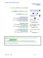
microFlex
Water Treatment Controller
For Cooling Towers
Measures Conductivity, Temperature,
Make-up Water Meter and Flowswitch
Controls the Bleed Solenoid
and Inhibitor Pump
Part No. CO-IN
microFlex: Water Treatment Controller
CONTENTS
Safety
1.
INSTALLATION
1.1
1.2
1.3
1.4
1.5
Sample Piping
Controller Enclosure
Sensors: Conductivity -Flowswitch
Sensors: Water Meter
Inhibitor Pump and Bleed Solenoid
2.
START-UP
2.1
2.2
2.3
2.4
2.5
2.6
2.7
Power-up Display & Keypad
Bleed Mode: Conductivity Setpoints
Inhibitor Feed Mode: Setpoints, Feed Limits
Verify Conductivity Sensor
Check Flowswitch & Install Water Meter
Plug-in Pump and Bleed Solenoid
Check Controls
3.
OPERATION
3.1
3.2
3.3
3.4
3.5
3.6
3.7
Conductivity Sensor
Bleed Controls
Make-up Meter
Inhibitor Controls
Diagnostics
System –Alarms
Password
4.
MAINTENANCE
4.1
4.2
4.3
Guidelines
Spare Parts
Technical Support
APPENDICES
A. INSTALL
B. SPECIFICATIONS
C. HARDWIRING
D. 4-20mA OUTPUT Option
E. ALARM RELAY Option
F. LAN - BROWSER Option
AQC2_User
02/06
2
microFlex: Water Treatment Controller
Safety
Electrical Shock Hazard
Opening the enclosure door with the controller plugged in,
exposes the user to AC line voltages.
Unplug the controller before opening the enclosure door.
USER WARNING : CAUTION
This Cooling Tower Water Treatment Controller operates a 120VAC bleed
solenoid & chemical feed pump and may pump hazardous, corrosive and
toxic chemicals.
Opening the controller enclosure exposes user to the risk of electrical shock
at power line voltages.
Understand fully the implications of the control setpoints, feed limit and
alarms that you select. Harm to personnel and damage to equipment may
result from mis-application.
Unplug or turn OFF the AC power to the controller if you have any concerns
regarding safety or incorrect controller operation and notify supervisory staff.
YOUR CONTROLLER
Controllers are supplied with default bleed solenoid and inhibitor feed
setpoints that will not be applicable to your cooling tower.
Select control modes, adjust setpoints and set pump timing for your site and
its water treatment program.
AQC2_User
02/06
3
microFlex: Water Treatment Controller
1. INSTALLATION
1.1
Sample Piping
The CO-IN Controller includes a conductivity- temperature-flowswitch sensor
pre-wired to the controller anda¾’NPTPVCent
r
yf
i
t
t
i
ng.
If you have not previously installed this type of controller,
read Appendix A: INSTALL for plumbing and wiring guidelines
AQC2_User
02/06
4
microFlex: Water Treatment Controller
1.2
Controller Enclosure
Install the controller enclosure corner mounting hardware,
available in the parts bag taped to back of enclosure.
Locat
et
hec
ont
r
ol
l
eratey
el
ev
el
,nomi
nal
l
y60”
,150cm.abov
et
hef
l
oor
Flow
Typical Equipment Layout
Controller
Inhibitor Pump
Chemical
Injection
point
Pump Shelf
Plugs, wiring
& tubing not
shown
Sensor
Inhibitor
Although sensor cables and pump tubing may be extended, ease of servicing occurs when
water treatment components are located in the same area.
Ensure that the controller enclosure door is closed & latched
when not terminating sensor and water meter wiring.
AQC2_User
02/06
5
microFlex: Water Treatment Controller
1.3
Sensors: Conductivity-Flowswitch
After installing the conductivity sensor, open the sample piping downstream valve,
then the upstream valve.
Verify that the sensor entry seals, leak and drip free
Conductivity - Temperature - Flowswitch
RUN
SENSOR
GRN WHT BLK RED
+15V
Flow
Meter
T S1 S2
Red
Controller
Black
White
Green
Conductivity
Temperature
&
Flowswitch
Sensor
Brown
Feed the sensor
cable through
the entry seal & tighten
the seal
Blue
Controllers are supplied with
the Sensor prewired
AQC2_User
02/06
6
microFlex: Water Treatment Controller
1.4
Sensors: Water Meter
Ref
ert
omanuf
act
ur
er
’
sr
ecommendat
i
onsonmet
eror
i
ent
at
i
onandupst
r
eam anddownst
r
eam
piping. Extend meter cables with AWG22, 2 or 3 conductor.
Do not install meter cabling in the same conduit at AC power wiring.
AQC2_User
02/06
7
microFlex: Water Treatment Controller
1.5
Inhibitor Pump & Bleed Solenoid
The controller supplies the AC power for the pump and solenoid.
Controller relays switch power to the pump and bleed solenoid,
fused at a maximum of 5 Amps.
WARNING:
Do not plug-in
controller, pump
or solenoid until you
are ready to setup
& operate
HARDWIRING:
r
ef
ert
oappendi
x‘
C’
INHIBITOR
PUMP - Back
BLEED
SOLENOID - Front
Grounded
Power Plug
START-UP
BEFORE you plug-in pump and bleed solenoid.
Plug-in the controller.
Set control modes and setpoints.
Set the feed limit on the inhibitor pump.
Verify that the sensor are reading correctly and set the alarms.
If you are using a water meter; force make-up and
verify that meter is measuring the expected volume.
Verify that the flowswitch is working.
An overview of system operation is available in the Yearly section of 4.1 Maintenance.
AQC2_User
02/06
8
microFlex: Water Treatment Controller
2. START-UP
2.1 Power-up Display & Keypad
UP & DOWN to view options
or to EDIT numbers
Move RIGHT to select next
field when EDITing
ENTER to select an option
& to execute EDITing
EXIT to escape option,
info display or EDITing
Enclosure keypad
Response
UP or DOWN to the
display you wish to
view or EDIT
& press ENTER
Unique Controller Serial Number
Press ENTER for Controller Diagnostic,
US-Metric select & to Turn ON Password.
Press ENTER to clear Alarms.
Current Conductivity sensor value.
Press ENTER for Conductivity Calibrate & Alarms.
Solenoid ON or OFF and ON time in the current 24 hours.
Press ENTER for Bleed Setpoints, Mode,
Test and Current State.
Water meter measured volume in the current24 hour period.
Press ENTER to Install, Select type,
View on-line total & days on-line.
Inhibitor Pump ON or OFF and ON time
in the current 24 hours.
Tower Control
S/N: D905CF042
Alarms
none
Conductivity
1425 uS
Bleed Solenoid
ON 10.1 hrs/day
12.4hr Make-up
10450 G
Inhibitor Pump
ON 108.2 min/day
Press ENTER for Inhibitor Setpoints, Feed Mode, Limit
Timer, Prime Pump and Current State.
AQC2_User
02/06
9
microFlex: Water Treatment Controller
2.1 Power-up Display & Keypad
continued
Flowswitch ON or OFF and ON time in most recent 24 hours.
Reset to zero on POWER OFF/ON.
Diagnostics over the most recent 24 hours.
Reset to zero on POWER OFF/ON
Last bleed, average bleed, max-mi
nt
emper
at
ur
e….
If there is no option card installed,
y
ou’
l
lv
i
ewt
heser
i
al
numberpower
-up display.
Flowswitch
ON 22.6 hrs/day
Diagnostics on
last 22.6 hrs
Tower Control
S/N: D041T0486
Option Displays
LAN –Browser, ‘
LB’Opt
i
on
Displays current IP –see Appendix F, for User Manual link.
LAN: Static
192.168.002.101
OR
4-20mAOut
put
,‘
CL’Opt
i
on
Displays loop current –see Appendix D,
‘
4-20mAOUTPUT’
f
orUserManual
Al
ar
m Rel
ay
,‘
AR’Opt
i
on
Displays relay state –see Appendix E,
‘
ALARM RELAY’
f
orUserManual
AQC2_User
02/06
4-20mA Output
15.4mA
OR
Alarm Relay
Closed
10
microFlex: Water Treatment Controller
2.2 Bleed Mode: Conductivity Setpoints
Thef
ac
t
or
ydef
aul
ti
s‘
Bleed on Conductivity’
Refer to 3.2 Bleed Controls
to select one of three Bleed Modes
Press UP or DOWN until you see
‘
Bleed Solenoid’
&pr
essENTER.
Press ENTER to view or adjust Setpoints.
Displays current bleed setpoints,
Varies with Bleed Mode
Press ENTER adjust Turn ON,
or DOWN & ENTER for TurnOFF.
Press UP-DOWN to adjust and RIGHT to move the cursor.
Press ENTER to execute or
EXIT to leave the Setpoints unchanged
Press ENTER, displays current setpoints.
Bleed Solenoid
ON 8.7 hrs/day
Setpoints
Bleed Mode
Turn ON
TurnOFF
1150
1140
Edit & Enter
Turn ON 1180
then
Turn ON
TurnOFF
1180
1140
If you make Turn ON less than TurnOFF,
the setpoints will be switched.
Setpoints for Bleed on Meter Control bleed mode
Measure 100 G
Bleed
20 sec
Water Meter Control
Setpoints for Percentage Time bleed mode
Percentage Time
15% each 5min
% Time Control
Sidebar: Thedi
f
f
er
enc
ebet
weenTur
nON&Tur
nOFF,t
he‘
deadband’
,i
sus
ual
l
ysett
o10uS.
If you are watching the tower conductivity as the sump float turns the make-up water ON &
OFF,y
ou’
l
lobser
v
et
heoperating deadband exceeds 10uS. The sump float mechanical
deadband is added to the controller deadband.
AQC2_User
02/06
11
microFlex: Water Treatment Controller
2.3
Inhibitor Feed Mode: Setpoints, Feed Limits
Thef
ac
t
or
ydef
aul
ti
s‘
Bleed & Feed’
Refer to 3.6 Inhibitor Controls
to select one of four Feed Modes
Press UP or DOWN until you see
‘
Inhibitor Pump’&pr
essENTER.
Press ENTER to view or adjust Setpoints.
Displays current feed setpoints,
Inhibitor will be on for 32% of the time that the Bleed
Solenoid is ON; 96 seconds in every 5 minutes
Press ENTER adjust % of Bleed Time,
Press UP-DOWN to adjust and RIGHT to move the cursor.
Press ENTER to execute or
EXIT to leave the Setpoint unchanged
Press ENTER, displays current setpoint,
90 seconds in every 5 minutes
Inhibitor Pump
ON 2.3 hrs/day
Setpoints
Feed Mode
Bleed & Feed
32% each 5min
Edit & Enter
30% each 5min
then
Bleed & Feed
30% each 5min
Sidebar: Bleed & Feed is the most common but usually not the best way to feed inhibitor.
If you are not bleed limited, use Bleed then Feed mode to reduce inhibitor use.
If you are using a make-up water meter to control inhibitor feed, the controller will delay
feeding when the bleed valve is ON to avoid pumping inhibitor down the drain.
AQC2_User
02/06
12
microFlex: Water Treatment Controller
2.3 Inhibitor Feed Mode: Setpoints, Feed Limits
continued
The Inhibitor feed limit timer turns OFF the inhibitor pump
to prevent overfeeding.
The factory default limit is 120 Minutes in a 24 hour period.
Press UP or DOWN until you see
‘
Inhibitor Pump’&pr
essENTER.
Press DOWN until Limit Timer.
Press ENTER to view or adjust Limit Timer.
Displays feed limit in minutes,
?157 indexes more explanation @ www.Aquatrac.com
Press ENTER adjust Feed Limit,
Press UP-DOWN to adjust and RIGHT to move the cursor.
Press ENTER to execute or
EXIT to leave the Feed Limit unchanged
Press ENTER, displays the current limit,
180 minutes in 24 hours.
Inhibitor Pump
ON 2.3 hrs/day
Limit Timer
Prime Pump
Day Limit ?157
120 min/day
Edit & Enter
180 min
then
Day Limit ?157
180 min/day
HELP: ?157 and other help numbers display wherever more explanation is available at
www.Aquatrac.com.
If you are using water treatment controls for the first time, the language and application of
some of the controller options and settings requires more detail than the controller 2 line
display can deliver.
AQC2_User
02/06
13
microFlex: Water Treatment Controller
2.4 Verify Conductivity Sensor
Open the downstream, then the upstream sample line
isolation valves, immersing the conductivity sensor
Press UP or DOWN until you see Tower Control .
Press ENTER.
Press ENTER & then press ENTER @ Current State
to view temperature at the conductivity sensor.
If the GREEN & WHITE wires are connected to the controller
terminals, y
ou’
l
lv
i
ewt
hecur
r
entt
emper
at
ur
e.
‘
Fault’i
ndi
cat
esawi
r
i
ngorsensorpr
obl
em.
‘
Fault’aut
omat
i
cal
l
yr
emov
esconduct
i
v
i
t
yt
emper
at
ur
e
compensation. Type=CTF indicates a ConductivityTemperature-Flowswitch sensor
Key EXIT twice to return to Serial Number
Press DOWN until you see Conductivity.
Sample the tower water & verify that the displayed
conductivity matches the measured conductivity.
Adjust the displayed conductivity by pressing ENTER twice.
Press UP-DOWN to adjust and RIGHT to move the cursor.
Press ENTER to execute or
EXIT to leave Conductivity unchanged.
Verify Temperature
Tower Control
S/N: D905CF042
Current State
Select Units
Temperature ?101
87F Type=CTF
Calibrate Conductivity
Conductivity
1425 uS
Calibrate
Alarms
Edit & ENTER
1883 uS
then
You’
l
lseet
hi
sscr
eeni
ft
hes
ens
ori
sf
oul
ed,mi
swi
r
ed,
not immersed or you keyed incorrectly.
Press ENTER to ignore or EXIT to return to Factory Default.
?141 indexes more explanation @ www.Aquatrac.com
Displays the current, calibrated conductivity.
AQC2_User
02/06
Advice
?141
Fails Calibrate
Conductivity
1883 uS
14
microFlex: Water Treatment Controller
2.5 Check Flowswitch & Install Water Meter
Open the downstream, then the upstream sample line
isolation valves, immersing the conductivity sensor
Press UP - DOWN until you see Flowswitch.
Displays ON or OFF and the total minutes ON
in the current 24 period.
Flowswitch
Flowswitch
ON 22.6 hrs/day
NOTE: An OFF flowswitch stops
the Inhibitor Pump and the Bleed Solenoid.
The flowswitch can be bypassed by jumpering the Flow
terminal to ground.
The factory default water meter is
a 100 Gallons/contact contact head meter.
Press UP - DOWN until you see 0 to 24hr Make-up.
Displays make-up volume during the current 24 hour period.
Make-up volume resets every 24 hours and
every power OFF/ON to 0.0 hours
Press ENTER twice to view or change meter type.
Press ENTER to view or change the gallons/contact.
Metric users wi
l
lv
i
ewvol
umesi
n‘
L’
i
t
er
s&L/
Cont
ac
t
Press UP-DOWN to adjust and RIGHT to move the cursor.
Press ENTER to execute or
EXIT to leave Gallons/contact unchanged.
Contact Head
Watermeter
23.2 hr Make-up
10450 G
Meter Type
Year-to-Date
Contact Head
Paddlewheel
G/Contact
100
Edit & ENTER
50
then
ENTER or EXIT displays the current meter type.
Contact Head
Paddlewheel
Sidebar: 2 wire meters are usually Contact Head type & 3 wire meters
are typically Turbine or Paddlewheel water meters.
AQC2_User
02/06
15
microFlex: Water Treatment Controller
2.5
Check Flowswitch & Install Water Meter
continued
Turbine-Paddlewheel type water meters provide
pulses per Gallon or Liter.
The number of Pulses/Unit Volume is the ‘
K’f
act
or
.
Press UP - DOWN until you see 0-24hr Make-up.
Displays make-up volume during the current 24 hour period.
Press ENTER twice to view or change meter type.
Press DOWN to select Paddlewheel type meter
Press ENTER to view or change the pulses per Gallon.
Metric users view pulses per Liter.
Press UP-DOWN to adjust and RIGHT to move the cursor.
Press ENTER to execute or
EXIT to leave ‘
K’Fact
orunchanged.
Turbine –Paddlewheel
Watermeter
6.4hr Make-up
31450 G
Meter Type
Year-to-Date
Paddlewheel
Contact Head
‘K’Factor
100.0
Edit & ENTER
104.5
then
ENTER or EXIT displays the current meter type.
Paddlewheel
Contact Head
Sidebar: Force make-up by either opening the bleed solenoid bypass or lowering the Bleed
Setpoints. Verify that the make-up meter displays an increasing volume as the float opens the
make-up line. Close bypass or reset Bleed Setpoints after verifying the meter.
WARNING: Verify paddlewheel meters immediately and disconnect if not verified.
Mis-wired paddlewheel meters will fail the meter Hall Effect sensor.
AQC2_User
02/06
16
microFlex: Water Treatment Controller
2.6
Plug-in Pump and Bleed Solenoid
Sections 2.1 to 2.5 adjust setpoints and verify sensors.
We’
r
enowr
eadyf
ort
hebl
eedsol
enoi
dandt
hei
nhi
bi
t
or
pump,v
er
i
f
y
i
ngeachoneasi
t
’
spl
ugged in.
Plug the bleed solenoid into the top, right plug.
Press UP or DOWN to view Bleed Solenoid.
If ON, verify that the green Bleed light
on the inside of the enclosure is ON.
Bleed Solenoid
Bleed Solenoid
ON 8.3 hrs/day
OR
Verify that the bleed solenoid is open
and that tower water is going to drain.
If OFF, press ENTER & DOWN to Test Bleed.
Press ENTER and the Bleed Solenoid & Bleed light
will turn ON for 5 minutes
Plug the inhibitor pump into the bottom, right plug.
Press UP or DOWN to view Inhibitor Pump.
If ON, verify that the green Inhibit light
on the inside of the enclosure is ON.
Verify that the pump is stroking, primed and feeding inhibitor.
If OFF, press ENTER & DOWN to Prime Pump.
Press ENTER and the Inhibitor Pump & Inhibit light
will turn ON for 5 minutes
Bleed Solenoid
OFF 8.3 hrs/day
then
Test Bleed
Current State
Inhibitor Pump
Inhibitor Pump
ON 2.3 hrs/day
then
Prime Pump
Current State
Inhibitor Pump
ON 2.3 hrs/day
Sidebar: The Bleed Solenoid and Pump will not turn ON unless the Flowswitch is ON.
The internal Bleed & Inhibit lights will not turn ON unless the Flowswitch is ON.
An Inhibitor Pump sett
o‘
Bl
eedt
henFeed’or‘
FeedonVol
ume’
modeswi
l
lnotf
eedi
ft
he
Bleed Solenoid is ON. Feed starts as soon as Bleed ends.
AQC2_User
02/06
17
microFlex: Water Treatment Controller
2.7 Check Controls
Verify that the controls work in the way
that you expect for this site.
Watch the Conductivity increase as the tower operates.
The Bleed Solenoid will turn ON as the Conductivity
exceeds the Turn ON setpoint.
As the tower makes up, the Conductivity will fall below the
TurnOFF setpoint and the Bleed Solenoid will turn OFF.
Conductivity & Bleed
Conductivity
1425 uS
Bleed Solenoid
ON 93.2 min/day
Verifying a Bleed controlled by a Make-up Meter or
Percentage time differs.
I
ft
heI
nhi
bi
t
orf
eedmodei
ssett
o‘
Bleed & Feed’
,t
he
Inhibitor Pump will turn ON when the Bleed turns ON.
If the % of each 5 minutes is set to less than 100%, the
Inhibitor Pump will turn ON & OFF while the Bleed is ON.
I
ft
heI
nhi
bi
t
orf
eedmodei
sset‘
Bleed then Feed’
,t
he
Inhibitor Pump will always be OFF when the Bleed is ON
& will turn ON as soon as the bleed turns OFF.
If the Inhibitor Pump i
ssett
o‘
Feed on Volume’,the
Inhibitor Pump will turn ON after measuring Make-up.
If the Bleed is ON, the Inhibitor Pump will wait until the
Bleed turns OFF before turning ON.
Water Meter or Bleed
& Inhibitor Pump
Bleed Solenoid
ON 10.2 hrs/day
Inhibitor Pump
OFF 108.1min/day
19.2hr Make-up
10450 G
Inhibitor Pump
OFF 108.1min/day
Sidebar: The Bleed Solenoid and Inhibitor Pump will not turn ON
unless the Flowswitch is ON.
The Inhibitor Pump turns OFF if the Feed Limit is exceeded.
Increase the Limit Timer & Clear Alarms to allow the pump to turn ON.
Feed limited inhibitor pumps reset every 24 hours of controller run time or on power OFF/ON.
AQC2_User
02/06
18
microFlex: Water Treatment Controller
3. OPERATION
3.1 Conductivity Sensor
Sensor calibration and temperature verify is detailed in
Section 2.4 Verify Conductivity Sensor
Press UP - DOWN until you see Conductivity.
Press ENTER & then DOWN to Alarms.
Press ENTER to view or adjust Alarms.
Press ENTER to adjust the High Alarm
or DOWN & ENTER to adjust the Low Alarm
Press UP-DOWN to adjust and RIGHT to move the cursor.
Press ENTER to execute or
EXIT to leave Alarm unchanged.
ENTER updates the alarms & displays the
current High & Low Alarms.
‘
Alarms’di
spl
ay
sConductivity on fault
and resets automatically if the measured conductivity is
between the High & Low alarm levels.
Alarms
Conductivity
1425 uS
Calibrate
Alarms
Alarms
Calibrate
High
Low
1600uS
1200uS
Edit & ENTER
High 155 0uS
then
High
Low
1550uS
1200uS
‘
Clear Alarms’doesnotr
esetac
onduct
i
v
i
t
yal
ar
m abov
et
he
High or less than the Low Alarm level.
Sidebar: A Conductivity alarm may occur when the tower shuts down
and drains the sample line.
AQC2_User
02/06
19
microFlex: Water Treatment Controller
3.2 Bleed Controls
For conductivity control setpoints see
Section 2.2 Bleed Mode: Conductivity Setpoints
Press UP - DOWN until you see Bleed Solenoid.
Displays ON or OFF and ON time
in the current 24 hour period.
Press ENTER to view or adjust Setpoints.
Setpoints vary with selected Bleed Mode.
Press ENTER view current mode or to select from
Conductivity Control, Percentage Time
OR Meter Control.
Press ENTER @ Test Bleed to turn ON
the Bleed Solenoid for 5 minutes.
‘
Alarms’
,ENTER and‘
Clear Alarms’,
ENTER ends the Test.
Press ENTER @ Current State to view control status.
Display varies with Bleed Mode.
Bleed Solenoid
ON 8.7 hrs/day
Setpoints
Bleed Mode
Bleed Mode
Test Bleed
Test Bleed
Current State
Current State
Setpoints
Sidebar: Test Bleed will not turn ON the Bleed Solenoid if the Flowswitch is OFF.
AQC2_User
02/06
20
microFlex: Water Treatment Controller
3.2 Bleed Controls
Continued
Bleed Solenoid Bleed Modes
Press ENTER then DOWN @ Bleed Solenoid
Bleed Solenoid
ON 8.3 hrs/day
then
Press ENTER @ Bleed Mode to view current mode
or to select a new mode
Most cooling towers operate with Conductivity Control.
Bleed Solenoid opens at TurnON conductivity setpoint
and closes at the TurnOFF setpoint
Bleed Mode
Test Bleed
Conduct.Control
Meter Control
Meter Control measures a user set volume on
the Make-up water meter then turns ON
the Bleed Solenoid for a user set time.
For example:
Measure 100 Gallons of make-up & bleed for 10 seconds.
Meter Control
Conduct.Control
Percentage Time turns ON the Bleed Solenoid
for a user set % of 5 minutes.
Percentage Time
Meter Control
then
NOTE: If you change the Bleed Mode, press UP to
Setpoints & ENTER to adjust for the new Bleed Mode.
Setpoints
Bleed Mode
Sidebar: Meter Control is used where sensor fouling from silica or organics continuously fouls
the conductivity sensor.
Percentage Time is used short term, to bleed while replacing a sensor or installing a water
meter.
AQC2_User
02/06
21
microFlex: Water Treatment Controller
3.2 Bleed Controls
Continued
Current State of the Bleed Solenoid Control
Press ENTER then UP @ Bleed Solenoid.
Bleed Solenoid
ON 8.3 hrs/day
then
Press ENTER @ Current State.
Conductivity Control
If ON, displays TurnOFF setpoint, 975.
& current conductivity,993.
If OFF, displays TurnOFF setpoint,1000.
& current conductivity,993.
Current State
Setpoints
Off@
975
ON 993uS
?121
Conductivity Control
Water Meter Control
If ON, displays Owes 101 sec ?122
& ON ENTER=Stop
If OFF, displays turn-on volume, 10400
& current volume 10,200
Percentage Time Control
If ON, displays Owes 41 sec ?123
& ON ENTER=Stop
If OFF, displays seconds to turn ON,
On @10400 G ?122
OFF 10200 G
Water Meter Control
On in 221sec?123
OFF
% Time Control
HELP: ?121,122 & ?123 and other help numbers display wherever more explanation is
available at www.Aquatrac.com.
The ON ENTER=Stop option ends the current bleed cycle or %Time ON period.
Control resumes when Make-up volume is measured if Water Meter Control or within 5
minutes if Percentage Time Control.
AQC2_User
02/06
22
microFlex: Water Treatment Controller
3.3 Make-up Meter
Meter type selection & installation detailed in
Section 2.5 Check Flowswitch & Install Water Meter
Press UP - DOWN until you see ’
Make-up’
& press ENTER .
18.2hr Make-up
10450 G
Press ENTER to view current type or to select
Contact Head or Paddlewheel water meter.
Meter Type
Year-to-Date
Press DOWN & ENTER for volume during the most
recent 365 days. Resets to zero every 365 days.
Year-to-Date
Days Online
Press DOWN & ENTER for the number of 24 hour periods of
powered up time in the current year
Days Online
Zero Meter?
Press ENTER to reset Year-to-date, Days OnLine
and 24 hr Make-up to zero.
Warning: Cannot Undo
Zero Meter?
Meter Type
Year-to-Date is updated every 24 hours of power ON.
Displ
ay
si
n‘
L’
i
t
er
si
fmet
r
i
csel
ect
ed.
Days water meter ON in current year.
Resets to zero every 365 days.
Year-to-Date?192
265200 G
Days Online ?193
28
Press EXIT to return to previous display
Sidebar: Year-to-date divided by Days OnLine is average usage,
a figure of merit for a tower tonnage.
HELP: ?192 & ?193 and other help numbers display wherever more explanation is available at
www.Aquatrac.com.
AQC2_User
02/06
23
microFlex: Water Treatment Controller
3.4 Inhibitor Controls
For inhibitor control setpoints & feed limit, refer to
Section 2.3 Inhibitor Feed Mode: Setpoints, Feed Limits
Press UP - DOWN until you see Inhibitor Pump.
Displays ON or OFF with time ON
in the current 24 hour period.
Press ENTER to view or adjust Setpoints.
Setpoints vary with selected Feed Mode.
Inhibitor Pump
OFF 93.1 min/day
Setpoints
Feed Mode
Press ENTER view current mode or to select from
Bleed & Feed, Bleed then Feed, Percentage Time
OR Feed on Volume.
Feed Mode
Limit Timer
Press ENTER to set maximum feed minutes
in a 24 hour period.
Limit Timer
Prime Pump
Press ENTER @ Prime Pump to turn ON the
Inhibitor Pump for 5 minutes.
‘
Alarms’
,ENTER and‘
Clear Alarms’,
ENTER ends priming.
Press ENTER @ Current State to view control status.
Display varies with Feed Mode.
Prime Pump
Current State
Current State
Setpoints
Sidebar: Prime Pump will not turn ON the Inhibitor Pump if the Flowswitch is OFF.
I
nhi
bi
t
orpumpss
ett
o‘
Bl
eedt
henFeed’or‘
FeedonVol
ume’
modeswi
l
lnotf
eed
if the Bleed Solenoid is ON. Feed starts as soon as Bleed ends.
AQC2_User
02/06
24
microFlex: Water Treatment Controller
3.4 Inhibitor Controls
Continued
Inhibitor Pump Feed Modes
Press ENTER then DOWN @ Inhibitor Pump.
Inhibitor Pump
ON 2.3 hrs/day
then
Press ENTER & DOWN @ Feed Mode to view
the current mode and to select a new mode
Feed Mode
Limit Timer
Bleed & Feed Mode
Inhibitor Pump turns ON when Bleed Solenoid ON.
Pump switches ON & OFF during bleed
at user set % of 5 minutes
Bleed & Feed
Bleed then Feed
Bleed then Feed Mode
Inhibitor Pump turns ON after Bleed Solenoid turns OFF.
Pump ON for user set % of Bleed time
Bleed then Feed
Percentage Time
Percentage Time Mode
Percentage Time turns ON the Inhibitor Pump
for a user set % of 5 minutes.
Water Meter Mode
Feed on Volume measures a user set volume on
the Make-up water meter then turns ON
the Inhibitor Pump for a user set time.
For example:
Measure 100 Gallons of make-up & feed for 8 seconds.
NOTE: If you change the Feed Mode, press UP to Setpoints
& ENTER to adjust for the new Feed Mode.
Percentage Time
Feed on Volume
Feed on Volume
Bleed & Feed
then
Setpoints
Feed Mode
Sidebar: Bleed & Feed is used on bleed limited towers where the bleed solenoid is ON for
more than 50% of the time.
Bleed then Feed i
sus
edont
ower
swhi
chdon’
thav
eamake-up water meter; typically
reducing inhibitor usage over Bleed & Feed since you are not pumping inhibitor
with the Bleed ON.
Percentage Time is used to base feed during start-up or when the tower is off line.
Feed on Volume is usually the most accurate & reliable way to feed for towers that have a
make-up meter.
AQC2_User
02/06
25
microFlex: Water Treatment Controller
3.4 Inhibitor Controls
Continued
Current State of the Inhibitor Pump Control
Press ENTER then UP @ Inhibitor Pump.
Inhibitor Pump
OFF 93.1 min/day
then
Press ENTER @ Current State
Bleed & Feed Mode
If Bleed Solenoid is ON: displays
Owes 233sec ?154
OR On in 86sec ?150
If the Bleed Solenoid is OFF: displays Bleed Off ?150
Current State
Setpoints
Owes 162sec ?154
ON ENTER=Stop
Bleed & Feed
Bleed then Feed Mode
If ON, displays Owes 101 sec ?150
If OFF,di
s
pl
ay
s‘
Bleed Off’
Bleed Off
OFF
?150
Bleed then Feed
Percentage Time Mode
If ON, displays Owes 41 sec ?156
If OFF, displays seconds to turn ON,
On in 267sec?156
OFF
Percentage Time
Water Meter Mode
If ON, displays Owes 38 sec ?154
If OFF, displays turn-on meter volume, 9800
& current meter volume 9700
On@
OFF
9800 G ?155
9700 G
Feed on Volume
Sidebar: Bleed & Feed applies the %of Bleed to each 300 seconds on Bleed ON time
Bleed then Feed applies the %of Bleed to the total Bleed ON time.
Feed on Volume feeds after the Bleed Solenoid turns OFF.
ON ENTER=Stop ends the current Feed on Volume cycle or %Time ON period.
HELP: ?150,?154,?155 & ?156 and other help numbers display wherever more explanation is
available at www.Aquatrac.com.
AQC2_User
02/06
26
microFlex: Water Treatment Controller
3.5 Diagnostics
Diagnostics displays operating information
from the last controller power OFF/ON.
This controller has been operating for 17.4 hours
from the last power OFF/ON
Diagnostics on
last 17.4 hrs
The time that the Bleed Solenoid is open depends on
sump volume, load and conductivity setpoints.
Last bleed ON
18.4 min.
An operating cooling tower would typically bleed
every 30 minutes to every two hours,
depending on setpoints, load and make-up float operation.
Bleed ended
1.2 hrs ago
Average Bleed is calculated over
a maximum of the most recent 24 hours.
Increasing Average Bleed time may indicate a change in
make-up chemistry or a restricted bleed
or a higher thermal load.
Average Bleed
14.2 min.
Pump ON time verifies setpoints and feed mode selection.
For example: If you are feeding ‘
Bleed then Feed’at 25% of
bleed time & the Last bleed ON = 21.5 min
then Last Feed ON = 32 sec.
If the Inhibitor Pump is controlled by the Bleed Solenoid,
you would see that the last Feed Ended
when the Bleed Ended.
If the Inhibitor Pump is controlled by the Make-up,
you would see that the last Feed Ended when
the Last make-up. occurred
If the Last make-up occur
r
edsev
er
alday
sago,t
her
e’
s
understandably a metering problem
Temperature max may influence biocide type & frequency.
Temperature min may indicate a switch to free cooling and
an increased sensitivity to flat plate exchanger fouling.
The usefulness of Diagnostic information varies with each
si
t
e’
st
ower, piping, water chemistry and treatment program.
AQC2_User
02/06
Last feed ON
26 sec.
Feed ended
1.2 hrs ago
Last make-up
58.4 min. ago
Temperature
84max, 61min
Last bleed ON
18.4 min.
27
microFlex: Water Treatment Controller
3.6 System- Alarms
System Menu Options
Press UP - DOWN until you see the Tower Control.
Press ENTER view System options.
Press ENTER to view Current State
Controller diagnostics
Press ENTER to view or change
US or Metric units.
Press ENTER to turn ON the controller Password.
For Edit Password, turning OFF the Password
and entering a Password refer to
Section 3.7 Password
Tower Control
S/N: D905CF042
Current State
Select Units
Select Units
Password ON
Password ON
Current State
Alarms
Press UP - DOWN until you see Alarms.
Thef
i
r
stal
ar
mt
ot
r
i
pwi
l
ldi
spl
ayor‘
none’i
fnoal
ar
ms
Press ENTER to Clear Alarms.
Clearing alarms sets pump & solenoid owed times to zero
and resets the Inhibitor Pump feed limit alarm.
Alarms
none
Clear Alarms
Conduc
t
i
v
i
t
ysensor‘
Out
-of-Cal
i
br
at
i
on’and High-Low Alarms
and System Alarms auto-clear when the problem
is corrected.
AQC2_User
02/06
28
microFlex: Water Treatment Controller
3.6 System- Alarms
continued
System : Current State
Press UP - DOWN until you see the Tower Control.
Press ENTER view System options.
Press ENTER to view Current State
Controller diagnostics
Temperature at the conductivity sensor.
Di
spl
ay
s‘
Fault’i
fnotusedt
ocompensat
ec
onduct
i
v
i
t
y
,
indicating a wiring or sensor problem.
Press ENTER to adjust Temperature.
External Power used for paddlewheel water meters
and to power 4-20mA current loops
Alarms on short circuits, recovers
automatically when wiring corrected.
Tower Control
S/N: D905CF042
Current State
Select Units
Temperature ?101
87F Type=CTF
Ext. Power ?102
15.6 VDC
Internal power used for Bleed Solenoid
and Inhibitor Pump relays.
Always displays 11.8 to 12.2. Alarms on fault.
Relay Power ?103
12.1 VDC
Conductivity sensor Drive displays, 72-76mV
or 990 –1020mV as the sensor drive auto-ranges.
Alarms and cannot measure conductivity if out of range.
Drive
?107
73.3 mV
Firmware Version.
Checks that user setpoints & options being saved
& that the internal Clocks are operating,
Thel
astdi
gi
tt
r
ackst
he24hourr
eset
soft
he‘
LB’webser
v
er
Ver: 71205
244:163:18
?106
Continued on next page
Sidebar: System: Diagnostics verifies the controller operation & alerts you to wiring problems
with conductivity temperature, paddlewheel water meters and controller powered 4-20mA
current loops.
AQC2_User
02/06
29
microFlex: Water Treatment Controller
3.6 System- Alarms
continued
Time from most recent power OFF-ON
If Up Time is always less than 24 hours then controller AC
power is being turned OFF daily.
Up Time 0 Yrs
26Days, 6Hrs
Controller operating time from installation
updated every hour.
If Powered time increases by 7 days every week, then the
controller is continuously operating.
Powered 2 Yrs
148Days,14Hrs
System : Select Units
Press UP - DOWN until you see the Tower Control.
Press ENTER & DOWN to Select Units.
Tower Control
S/N: D041T0486
then
Press ENTER to view or adjust current Select Units.
Select Units
Current State
Press EXIT to leave changed
or DOWN to change.
Deg F, Gallons
Deg C Liters
Key ENTER to:
Set to U.S. units, degrees Fahrenheit & Gallons
or
Set to Metric, degrees Centigrade & Liters
Deg C Liters
Deg F, Gallons
Sidebar: Select Units changes make-up meter units, total volume units and volume per
contact units.
Temperature compensation of conductivity, switches automatically between C & F as does the
System:Current State display of temperature.
AQC2_User
02/06
30
microFlex: Water Treatment Controller
3.7 Password
Password is turned OFF in new controllers
Turning ON Password
Press UP - DOWN until you see Tower Control.
Tower Control
S/N: D905CF042
Press ENTER & DOWN to select Password ON
Current State
Select Units
&
If you press ENTER y
ou’
l
lbepr
ompt
edf
orapassword then
next time you press ENTER.
Password ON
Current State
Password ON
Press UP or DOWN to view the current state of the controller.
Any ENTER key will prompt for the password,
displaying the default password 123.
Enter Password
000123
then
Use the UP, DOWN & RIGHT keys to enter a password
then key ENTER.
A correct password displays, Password OK.
Press any key to start operating the controller.
Press ENTER to re-key an incorrect password
Advice
?110
Password OK
OR
Advice
?111
Wrong Password
Sidebar: When you first select Password ON, the default password is 123.
Whenever you Enter Password the controller displays the default password.
If you have not changed the default password, press ENTER to log in.
AQC2_User
02/06
31
microFlex: Water Treatment Controller
3.7
Password
continued
Press UP - DOWN until you see Tower Control.
Then press ENTER & UP to view Password tools.
Password
Current State
Password tools are available when Password is ON
and you are logged in. Press ENTER to view the tools:
Press ENTER to Log Out.
If you forget to Log Out, the controller logs you out
30 minutes after the last key press
and on controller power OFF/ON.
Press DOWN & then ENTER to view
& change the current password
Press DOWN to Password OFF.
Pressing ENTER turns OFF Password.
Log Out
Edit Password
Edit Password
Password OFF
Password OFF
Log Out
Edit Password
Press RIGHT & UP –DOWN to change
the current password.
Edit & ENTER
0094502
ENTER changes the password.
Press EXIT to leave the password unchanged
then
Log Out
Edit Password
Sidebar: If your controller is password protected. Select Edit Password and change the
passwor
df
r
om t
he‘
123’
f
act
or
ydef
aul
t
.
Passwords may be from 1 to 6 numbers. Leading zeros are ignored.
If you forget yourpass
wor
d,y
ou’
l
lr
equi
r
et
hecont
r
ol
l
erser
i
al
numbert
ogetaReset
Password from the controller manufacturer.
Thecont
r
ol
l
erpasswor
di
s‘
123’af
t
ery
oukeyi
nt
heReset Password.
AQC2_User
02/06
32
microFlex: Water Treatment Controller
4. MAINTENANCE
4.1 Guidelines
Modify the maintenance guidelines to reflect both the site priorities
and the site water treatment program.
Guidelines are for controller function only. Water treatment program maintenance
requirements are provided by the site water treatment provider.
Frequency
Daily
Activity
Check for Alarms.
Method
Identify and correct the cause of alarms on sensor
and Inhibitor Pump.
Make-up water or Pump rate & stroke may have
changed. Higher temperatures may be extending
inhibitor ON times. Debris may have partially blocked
the bleed line.
A high conductivity may indicate a blocked or failed
bleed solenoid. A low conductivity may indicate an
overflowing tower basin.
Scan Sensors,
Make-up Meter
& Flowswitch
I
ft
her
e’
samak
e-upmet
er
,y
ou’
dex
pectdai
l
yv
ol
ume
to increase with temperature. High make-up may
indicate a stuck make-up float. No make-up may
indicate a valved-off or faulted meter & the cause of
low run time on the inhibitor pump.
If the cooling tower is on line, verify that the
Flowswitch shows ON.
If you check at the same time every day you would
expect the bleed solenoid and inhibitor pumps ON
times to vary only with temperature.
Zero Bleed solenoid time may indicate a fouled
conductivity sensor.
Typical cooling towers bleed no more than 40% of the
time and feed 5-10% oft
het
i
me.Af
t
er12hour
sy
ou’
d
expect to see 100 to 200 minutes of bleed & 20 to 50
minutes in inhibitor pump time.
AQC2_User
02/06
33
microFlex: Water Treatment Controller
Frequency
Weekly
Activity
Verify Conductivity
Method
Sample the tower water conductivity.
Verify controller matches the sample +/-25uS
Conductivity sensors should not drift or require
cleaning.
Scaling sensors may indicate a restricted bleed,
varying make-up hardness, incorrect Bleed Solenoid
setpoints or water treatment program.
Fouled sensors may indicate organic, biofilms, oils or
silica. Depending on the type of foulant, a change in
program or a switch in the bleed control method may
be required.
Note Make-up Volume Weekly water usage indicates both average tower
load and maximum daily temperature. High water
usage may result from a change in controller
setpoints or a leak or overflow in the cooling water
system.
Verify Flowswitch
Close the upstream sample line isolation valve
then the downstream valve & verify that the
Flowswitch displays OFF within 10 seconds of valve
closing.
‘
Y’St
r
ai
nerFi
l
t
er
I
ft
hesampl
el
i
nehasa‘
Y’st
r
ai
ner
,cl
eant
hef
i
l
t
ert
o
pr
ev
entanunpl
anned‘
nof
l
ow’out
age.
Open the downstream, then the upstream valve
and verify that the Flowswitch displays ON within 10
seconds of valve opening
System Check
Visually inspect sample-injection piping for leaking
fittings, feed injection point and sensor entries.
Sidebar: Maintenance Guidelines for water treatment are set by
the chemical treatment program vendor.
AQC2_User
02/06
34
microFlex: Water Treatment Controller
Frequency
Yearly
Activity
Method
Calibrate Conductivity
Tester
Verify the conductivity tester annually with a
calibrat
i
ons
ol
ut
i
onusi
ngasol
ut
i
ont
hat
’
sascl
oseas
possible to the controller conductivity setpoints.
Replace outdated calibration solutions.
Observe a Bleed
Control Cycle
Observe as the tower cycles up and the conductivity
exceeds the Turn ON setpoint. Observe the
unobstructed flow fr
om t
hebl
eedl
i
ne,i
fi
t
’
sv
i
si
bl
e.
Note the conductivity when the float opens the makeup line. Verify that the bleed solenoid shuts off flow
when the conductivity falls below the lower setpoint.
Note the conductivity when the float closes the makeup line. Verify that the difference between Make-up
ON & OFF conductivities is greater than the
difference between Setpoint TurnON & TurnOFF
conductivities.
Optimal control occurs when the bleed setpoint
deadband (TurnON –TurnOFF) is less than the
make-up float ON-OFF conductivity difference.
Verify Water Meter
If a make-up water meter is installed, verify that the
controller measures an increase in make-up volume
while the make-up float opens the make-up line.
Is the expected volume measured for the size of the
line and the float ON time?
I
fnot
,t
hemet
erVol
ume/
Cont
actor‘
K’
f
act
ormay
have been set incorrectly or the water meter may
have been cabled in a common conduit with AC
power.
AQC2_User
02/06
35
microFlex: Water Treatment Controller
4.1 Spare Parts
4.1.1 Line Fuse
Protects
Manufacturer –Vendor
Rating / Type
Controller,
Pumps and Bleed
Solenoid
Littlelfuse, Type 217, 250VAC
5 Amps @ 115VAC Digikey Part# F953-ND
5mm x 20mm, www.digikey.com 1-800-344-4539
Fast Acting
4.1.2 Controller Parts
Part#
Description
SFuse
120VAC Fuse Kit, 10 x 5A Controller Fuses,
CTF
Conductivity-Temperature-Flowswitch sensor
S-E3/4
Conduc
t
i
v
i
t
yent
r
yf
i
t
t
i
ngf
or3/
4NPT PVC‘
T’
CO-IN-NS
Spare Controller without sensors & entry fittings
R171230
Enclosure Power cable entry fitting, PG11
R717231
Enclosure Sensor cable entry fitting, PG9
On-Line Help
Browse to www.aquatrac.com/help wi
t
ht
he3di
gi
tHELP#’
f
r
om t
hecont
r
ol
l
erLCDdi
spl
ay
.
LCDdi
spl
ayHELPnumber
sar
epr
ec
ededby‘
?’
Users Manual
Download AQC2_User.pdf from aquatrac.com
Manual Version
AQC2_User
Detail
07/05
Issued with initial field trial controllers
02/06
CO-IN Production
02/06
36
microFlex: Water Treatment Controller
Appendix A: INSTALL
A.1 PLUMBING
Typical sample-chemical injection piping operates at 40-60psi and is plumbed in solvent
welded SCH40 or SCH80 PVC.
Sample piping is usually fed from the discharge side of the re-circulation pump, returning to
either the suction side of the pump or to the tower basin.
Ensure that the sample piping flow exceeds 1 GPM and that the sample stream represents the
tower water.
Avoid sample piping which drains whenever the tower is off-line. Solids will accumulate on the
sensors requiring re-calibration and cleaning.
‘
Y’st
r
ai
ner
si
nt
hes
ampl
el
oopar
enotr
ecommendedunl
esst
hedebr
i
swi
l
lmechani
cally
damage the conductivity sensor. Strainer filters are usually the first location to plug, turning
OFF pumps and the bleed solenoid on no flow.
NEW CONSTRUCTION: After pressure testing, valve OFF the sample piping during postconstruction re-circulation piping cleaning and passivation.
A.2 SENSORS
Conductivity sensors may be installed in any orientation which allows removal for cleaning. Do
not hang conductivity sensors in metallic tower sumps.
Water meter and sensor wiring cannot be installed in the same conduit as 120VAC power,
pump or solenoid wiring. Even a short section of shared conduit may cause operational
problems.
Sensor wires may be extended up to 50 feet, 15m using multiple pair AWG22 cable. Always
splice sensor wires in an electrical fitting to allow both inspection and sensor replacement.
Extend the conductivity sensor using the same colors as the sensor to avoid wiring errors at
the controller terminals.
Contact head water meters and mechanical flowswitches are not polarized, simplifying cable
extension.
CAUTION: Three wire turbine-paddlewheel meters are polarity sensitive and can be
permanently damaged by miswiring. Wait until you are ready to start-up the controller before
connecting this type of meter to the controller. Meter wiring errors are easily detected and
corrected at start-up.
A.3 CHEMICAL INJECTION
Inject water treatment inhibitor downstream of the conductivity sensor as recommended by the
chemical supplier.
AQC2_User
02/06
37
microFlex: Water Treatment Controller
A.4 BLEED LOCATION
The optimum bleed solenoid location is after the condenser –heat exchanger.
Never install the bleed on the sample line, upstream of the sensors and flowswitch.
If you are installing a bleed solenoid on the tower sump, ensure that the head or pressure at
the bleed solenoid is sufficient to operate the solenoid.
Verify that the solenoid is sized for the maximum tower load at the target cycles, on the hottest
day of summer. If the bleed is on for more than 50% of the time, inhibitor feed options will be
limited.
A.5 MAKE-UP METER
Ensure that the met
ermanuf
ac
t
ur
er
’
sr
ecommendat
i
onsf
oror
i
ent
at
i
onandupst
r
eam and
downstream piping are observed.
Orientation may be limited for contact head meters, while straight upstream and downstream
piping is required to prevent errors in turbine-paddlewheel meters.
Contact head meters have a Gallon/Contact or Liter/Contact rating. In some meters this value
can be altered by moving magnets or gears. Typical meters are rated 10, 50 & 100
Gallons/contact.
Turbine-Paddl
ewheel
met
er
shav
ea‘
K’Fact
orwhi
chi
st
henumber of pulses / Gallon or
pulses/Liter. Some manufacturers have both nominal values listed by meter size and
calibration values on the meter body.
Tak
et
het
i
met
ogett
hemet
erv
ol
ume/
cont
ac
tor‘
K’
f
ac
t
orcor
r
ect
,si
ncemostmet
er
sar
eused
to control inhibitor feed and inhibitor ppm errors result when meters are incorrectly configured.
A.6 CONTROLLER ENCLOSURE
The optimum location for sensor, controller, chemical pump and drum is as close together as
accessal
l
ows.You’
l
lbeabl
et
oseewher
eal
lt
hewires, plugs and tubing goes, watch the
pumpt
ur
nONasy
oupr
i
me,gr
abasampl
et
ocal
i
br
at
econduc
t
i
v
i
t
y…
If you have the space; locate sample piping on the left, pump & chemical drum on the right with
the controller in the middle.
Wall mount the controll
erencl
os
ur
eatey
ehei
ghtf
ora5’t
o5’
6”per
sonsot
hatanoper
at
or
does not have to reach over drums or pumps to use the controller key pad.
In areas with daily ambient temperatures over 100F, 40C, locate the controller out of direct
sunlight or beneath a sunshade. Internal temperatures over 115F, 45C will degrade the
controller LCD display.
Do not punch conduit access holes in the top of the enclosure to avoid condensation damage
to the controller electronics.
Pl
ugt
hec
ont
r
ol
l
eri
nt
oan‘
Al
way
sON’ut
i
l
i
t
yout
l
et
.
Maximum controller current @ 120VAC is 5 Amps.
AQC2_User
02/06
38
microFlex: Water Treatment Controller
Appendix B: SPECIFICATIONS
Each controller includes an option card slot.
Auto re-configuration occurs on installation of one of LAN -Browser, 4-20mA Output
OR Alarm Relay option card.
Analog –Digital I/O
Rating - Detail
CTF: Conductivity
Temperature
Flowswitch
Sensor
1 Temperature Compensated
conductivity sensor.
Water Meter &
Flowswitch Inputs
Flowswitch, Dry Contacts,
Displays 1uS resolution.
Rated 100psi
Flowswitch trips @ 1GPM within 30
seconds from 32-125F, 0-50C.
250mS response.
Water Meter, 400 Hz max
0.5mA @ 5VDC measurement
current
Relay Outputs
1
SPDT, Bleed Solenoid or
Motorized Valve
1
SPST, Inhibitor Pump
4-20 ma Output
on conductivity
(CL: optional card)
1, DC isolated, loop powered.
Alarm Relay
(AR: optional card)
Dry contact set.
Rated 500mA @ 24VDC
Communications
User Interface
Keypad - LCD
Nominal 0.1% resolution.
Auto polarity correction field wiring.
Rating –Detail
5 Key Tactile feedback: UP /
DOWN / ENTER / EXIT / RIGHT
Notes
Autoranging from 100uS to
10000uS.
CTF integral flowswitches
typically trip within 10 seconds
of flow ON/OFF.
Contact head meter, software
debounced.
Turbine-Paddle wheel rating =
Seametrics max pulse rate.
Relays rated 10A, 120VAC
Controller fused @ 5 Amps
Alarms on open 4-20mA loop.
Auto-configure on
Driver installation and removal
Software calibration of span &
zero
Closed in the non-alarmed
state.
Contact set opens on alarm or
loss of controller power.
Notes
Scan rate 100mS nominal
User adjustable LCD contrast
2 Line x 16 Character, Backlit
Browser
(LB: optional card)
10BaseT Ethernet RJ45 Jack
Full command & control via
Internet Explorer & Mozilla Firefox
browsers.
User set Static IP, defaulted to
10.10.6.101.
DHCP available on request.
Fixed, viewable MAC.
XML real time controller data
AQC2_User
02/06
39
microFlex: Water Treatment Controller
Controls
Rating –Detail
Bleed Solenoid
Controls: Conductivity, Water
Meter & Percentage Time.
Inhibitor Pump
Controls: Bleed & Feed, Bleed then
Feed, Feed on Volume &
Percentage Time
Notes
User sets % of Bleed ON time
used for Inhibitor feed.
Feed limit timer, reset every 14
hours.
Flowswitch
System
Controller Configuration
Electrical
Bleed Solenoid & Pumps OFF
when Flowswitch contact set
opens.
Rating - Detail
User settings and configuration
written on silicon.
Rating - Detail
Flowswitch included in
Conductivity sensor
Notes
Makes user configuration the
factory default.
Notes
AC Input
115 VAC, 50/60Hz,
Fusing
5 Amps @ 115VAC
5x20mm, 120VAC fusing:
Bleed solenoid relay contacts
snubbed 0.1uF, 150R
Controller electronics
transformer isolated from AC
line
Surge-Spike Suppression
Varistor on AC power input
AC Terminals
AC Input & Output :
maximum. Stranded AWG 14,
150mm2
Sensor, Digital Input
Terminals
AWG 22, 0.25 –0.50mm2
Paddlewheel Meter Power
4-20mA output loop power
14 –20 VDC, unregulated
Mechanical
Enclosure
Thermally fused @ 50mA
Rating
Non-metallic, NEMA4X,
”
5.
9W x”
5.
9Hx3.
5”
D
150mmW x150mm H x 90mm D
4-20mA output option can be
powered by load or by controller
Notes
Nominal dimensions, excluding
entry fittings and flexible
conduit.
Enclosure door hinged left.
Al
l
ow8”
,r
i
ghtf
ordooropeni
ng
Al
l
ow18”
,bel
owf
orcabl
e
access.
AQC2_User
02/06
40
microFlex: Water Treatment Controller
Appendix C: HARDWIRING
Controller are shipped with pre-wired AC power cord, Solenoid & Inhibitor
AQC2_User
02/06
41
microFlex: Water Treatment Controller
Appendix D: 4-20mA Output Option
The optional 4-20mA output on conductivity is DC isolated from the controller & may be either
powered by the load or by the controller DC supply. The 4-20mA output is auto-polarity
correcting.
D1. WIRING
LOAD POWERED 4-20mA Output
Fuse
4-20mA
Output on
Conductivity
RUN
SENSOR
Auto Polarity
Correction
+15V
Flow
GRN WHT BLK RED
Inhibit Bleed
T S1 S2
L NEUTRALS In Bs Bv
Meter
4-20
mA
The Monitoring or Distributed Control
system powers the controller current
loop with 18-24VDC and reads
controller conductivity
2 Conductor
AWG22 to AWG18
Cabling
Terminate current
loop at DCS input
with 50 to 250 ohms
+24V IN
4-20mA Input
Distributed
Control System
Controller alarms
when monitoring
current loop
disconnected
CONTROLLER POWERED 4-20mA Output
Fuse
4-20mA
Output on
Conductivity
RUN
SENSOR
Auto Polarity
Correction
GRN WHT BLK RED
+15V
Flow
Meter
T S1 S2
Inhibit Bleed
L NEUTRALS In Bs Bv
4-20
mA
The Controller powers the current loop
output used to control the pump or
valve on conductivity
+ Loop Powered
Pump or Valve
Proportional
Control
AQC2_User
02/06
+15V Controller Supply
Thermally fused
at 50 ma to protect
Controller and Pump
42
microFlex: Water Treatment Controller
Appendix D: 4-20mA Output Option
D.2 VIEW & ADJUST SPAN
The displayed value of the 4-20mAloop current
depends on both the conductivity and the Span
4-20mA Output
15.4mA
OR
If the current loop out
puti
sdi
sconnec
t
edy
ou’
l
lseet
hi
s
display in place of the mA level.
Press ENTER @ Select Span to view or adjust the Span
Span sets the conductivity at 4mA & at 20mA
Press ENTER @ Trim Zero to calibrate the 4mA level
Press ENTER @ Trim Span to calibrate the 20mA level
4-20mA Output
Disconnected!
Select Span
Trim Zero
Trim Zero
Trim Span
Trim Span
Select Span
View & Adjust Span
Press ENTER @ 4-20mA Output
& then DOWN to Select Span
Press ENTER.
Displays current Span.
Press ENTER to adjust 4mA level
or DOWN & ENTER to adjust 20mA level.
Press RIGHT to place the underline
under the digit you wish to adjust.
Press UP –DOWN to adjust.
ENTER updates the Span.
EXIT leaves Span unchanged
AQC2_User
02/06
Select Span
Trim Zero
4mA=
20mA=
100uS
5000uS
Edit & ENTER
4mA= 2 500uS
then
4mA=
20mA=
2500uS
5000uS
43
microFlex: Water Treatment Controller
Appendix D: 4-20mA Output Option
D.3 CALIBRATE
Calibration is seldom necessary & is used to correct to offset errors.
The range of Zero & Span adjustment is limited.
If you are not able to calibrate:
A: Verify your milli-ammeter B: If Load Powered, verify you have at least 15VDC available.
Press ENTER & then DOWN
at 4-20mA Output
4-20mA Output
15.4mA
AND
Press ENTER at Trim Zero to adjust the 4mA level.
Connect a DC milli-ammeter in series
with either of the current loop wires.
Trim Zero
Trim Span
Trim Zero
?201
now 4mA
6
Press UP or DOWN until you read 4mA on the milli-ammeter.
Press ENTER to view the output current and verify that the
milli-ammeter reads the same current.
Press ENTER & then DOWN
at 4-20mA Output
4-20mA Output
15.2mA
4-20mA Output
15.4mA
AND
Press ENTER at Trim Span to adjust the 20mA level.
Connect a DC milli-ammeter in series
with either of the current loop wires.
Trim Span
Select Span
Trim Span
?202
now 20mA 9 1
Press UP or DOWN until you read 20mA
on the milli-ammeter.
Press ENTER to view the output current and verify that the
milli-ammeter reads the same current.
AQC2_User
02/06
4-20mA Output
15.2mA
44
microFlex: Water Treatment Controller
Appendix E: Alarm Relay Option
E.1 WIRING ALARM CONTACTS
Alarm contacts rated 500mA at 24VDC.
Requires optional Alarm Relay Card
RUN
ON when
not Alarmed
SENSOR
Flow
+15V
Alarm
Relay
Fuse
Option: AR
Alarm Relay
Dry Contacts
Open
On Alarm
GRN WHT BLK RED
Inhibit Bleed
T S1 S2
L NEUTRALS In Bs Bv
Meter
OK
Alarm dry contacts OPEN on alarm,
loss of controller power & alarm
wiring disconnect
Alarm
Alarm
Building Automation System
Alarm Input
Wire alarm contacts AWG22 to
AWG18, 2 conductor
E.2 ALARM DISPLAYS
Press UP - DOWN until you see Alarms
I
ft
heAl
ar
m Rel
ayCar
di
si
nst
al
l
edy
ou’
l
lseeoneoft
he
following displays.
I
fAl
ar
ms&‘
none’t
hent
heal
ar
m cont
act
swi
l
lbecl
os
ed
Alarms
none
Alarm Contacts
CLOSED,No Alarm
OR
Alarm contacts open on alarm.
This display verifies the contact set state measured at the
Building Automation System input terminals.
AQC2_User
02/06
Alarm Contacts
OPEN,Alarm
45
microFlex: Water Treatment Controller
Appendix F: LAN - Browser Option
Download Sflex_LB manual from www.Aquatrac.com/manuals.
Do not connect the controller to the site LAN without permission from the site IT staff.
The factory default IP is 10.10.6.101.
The controller micro-server uses a static IP. Set the controller IP to the IP assigned by the site
IP staff before connecting the controller to the site LAN.
You can use a crossover cable to connect to your notebook PC to view the controller state.
Information on browsing controllers is available in the TACO_LAN manual.
AQC2_User
02/06
46