1
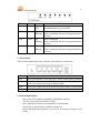
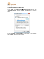
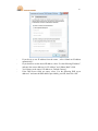
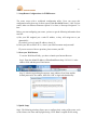
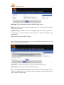
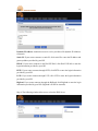
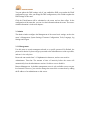
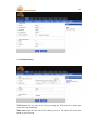
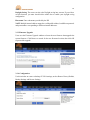
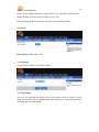
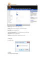
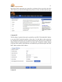
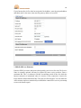
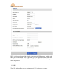
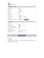
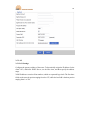
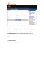
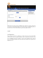
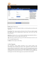
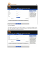
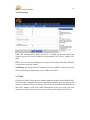
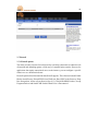
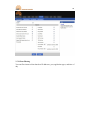
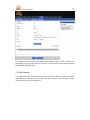
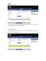
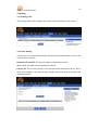
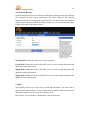
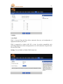
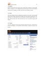
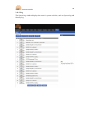
Manual Router OT-2504 2 Directory 1. Introduction ................................................................................................... 04 1.1 Feature and Benefits……………………………………………………….. 04 1.2 Package Contents ………………………………………………………….. 04 1.3 Finding Your Way Around………………………………………………… 04 1.3.1 Front Panel……………………………………………………………... 04 1.3.2 Rear Panel……………………………………………………………… 05 1.4 System Requirement……………………………………………………….. 05 1.5 Installation Instruction……………………………………………………... 06 2. PC Configuration…………………………………………………………... 07 2.1 Checking TCP/IP Settings For Windows Seven………………………….... 07 3. Setup Router Configurations via Web Browser……………………………. 09 3.1 Start your Web Browser……………………………………………………. 09 3.2 Quick Setup………………………………………………………………… 09 3.3 Admin………………………………………………………………………. 12 3.3.1 Management……………………………………………………………. 12 3.3.2 System Settings………………………………………………………… 13 3.3.3 Firmware Upgrade……………………………………………………... 14 3.3.4 Configuration…………………………………………………………... 14 3.3.5 Tools……………………………………………………………………. 15 3.3.6 Language……………………………………………………………….. 15 3.3.7 Log Settings……………………………………………………………. 15 3.3.8 Logout………………………………………………………………….. 16 3.4 Wan…………………………………………………………………….. 16 3.4.1 Wan Connection Mode………………………………………………… 16 3.5 Lan……………………………………………………………………… 22 3.5.1 Lan Settings……………………………………………………………. 22 3.5.2 DHCP Client List………………………………………………………. 23 3.6 NAT……………………………………………………………………. 24 3.6.1 Virtual Server…………………………………………………………... 24 3.6.2 Port Triggering ………………………………………………………… 25 3.6.3 Port Mapping…………………………………………………………… 26 3.6.4 Passthrough…………………………………………………………….. 27 3.6.5 DMZ……………………………………………………………………. 27 3.7 Firewall………………………………………………………………… 28 3.7.1 Firewall Options………………………………………………………... 28 3.7.2 Client Filtering…………………………………………………………. 29 3.7.3 URL Filtering………………………………………………………….. 30 3.7.4 MAC Filtering………………………………………………………….. 31 3.8 Routing ………………………………………………………………… 32 3.8.1 Routing Table…………………………………………………………... 32 3.8.2 Static Routing………………………………………………………….. 32 3.8.3 Dynamic Routing………………………………………………………. 33 3 3.9 3.10 3.10.1 3.10.2 3.11 3.11.1 3.11.2 QOS…………………………………………………………………….. 33 Misc……………………………………………………………………. 34 UPnP…………………………………………………………………… 34 DDNS…………………………………………………………………... 35 Status…………………………………………………………………... 35 Status…………………………………………………………………… 35 Log…………………………………………………………………...… 36 4 1 Introduction Congradulations on purchasing Broadband Router. This router, is a high quality and reliable Internet routing device, enables multiple users to share the internet connection through a Cable or DSL modem. Simply install the router, connect to Cable/DSL modem, and surf Internet without extra efforts. Acting as a 10/100Mbps 4- port Ethenet switch as well, the router, with all ports supporting MDI/MDIX, allows you to use CAT5 cable to uplink to other routers/swtiches. The router provides a total solution for the Small and Medium-sizes Business (SMB) and the Small Office/Home Office (SOHO) markets, giving you an instant network today, and the flexibility to handle tomorrow´s expansions and speed. 1.1 Feature and Benefits - - - 4-step easy setup wizard All users can easily setup the router via only 4-step wizard to share internet. User friendly Web Graphical Interface. Broadband Router specific and user friendly interface allows users to easily set up the router. DHCP server support This feature provides a dynamic IP address to PCs and other devices upon request. The router can act as a DHCP server for devices on your LAN. Support PPTP and PPOE The internet (Wan port) connection supports PPPoE (PPP over Ethernet) and PPTP (Point-to-Point Tunnel Protocol), as well as “Direct Connection” type service. 1.2 Package Contents - One Broadband Router AC external adapter User manual 1.3 Finding Your Way Around 1.3.1 Front Panel The front panel contains LED indicators that show the status of the unit. 5 LED Power Color Green Status ON OFF Extinct Blinking SYS Green WAN Green ON Blinking LAN (1-4) Green ON Blinking Indication Broadband Router is powered ON. Broadband Router is powered OFF. CPU hasn´t been started Link is established, and data is being transmitted or received. Link is established Link is established, and data is being transmitted or received Link is established Link is established, and data is being transmitted or received. 1.3.2 Rear Panel The rear panel contains the ports for the unit´s data and power connections. Label Reset LAN(1-4) WAN Power Indication Reset: Reset button (3-5s for the reset, 6-10s for restoring factory settings) LAN Ports: connects to your PC´s Ethernet port, or to the uplink port on your LAN´s hub/switch, using the Ethernet cable. WAN port: connects to yout WAN device, such às ADSL or cable modem Power Input Jack: connects to the supplied AC adapter. 1.4 System Requirements - One or more PCs (desktop or notebook) with Ethernet interface. TCP/IP protocol must be installed on all PCs. Have valid internet Access account and DSL or cable modem. 10/100 Base T network cables with RJ-45 connectors. System with MS internet Explorer ver 5.0 or later, or Netscape Navigator ver 4.7 or later. 6 1.5 Installation Instruction 1) Power off the router and DSL/cable modem. 2) Connect system to the LAN ports on the router with straight LAN cables. 3) Connect the DSL or cable modem to the WAN port on the router. 4) Power on DSL or cable modem firstly, the connect power adapter to the power jack on the router and plug the power cable into an outlet. 5) Check LEDs. a) Once power on the router. Power LED should be on. b) LAN LED should be on for each active LAN connection. c) The WAN LED should be on when the DSL or cable modem is connected. 7 2 PC configuration 2.1 Checking TCP/IP Setting for Windows Seven a) Click “Start”, select “Control Panel” Network Connection” and right click “Local Area Connection” the select “Properties”, the windows shown as below will appear. b) Select the “Internet Protocol (TCP/IP)” for the network card on your system, the click “Properties”, the windows below will appear. 8 - If you device to use IP address from the router , select “Obtain an IP address automatically ”. IF you decide to use the desired IP address, select “Use the following IP address”, and enter the correct addresses in “IP Address” and “Subnet Mask” fields. You´d better set the router´s IP address as “Default Gateway”. If the DNS Server fields are empty, select “Use the following DNS server addresses” and enter the DNS address provided by your ISP, then click “OK”. 9 3 Setup Router Configurations via WEB Browser. The router comes with a web-based configuration utility. Users can access this configuration utility from any of client system within Broadband Router´s LAN. For best results, either user Microsoft internet explorer 5.0 or later, or Netscape Navigator 4.7 or later. Before you start configuring your router, you have to get the following information from tour ISP: a) Has your ISP assigned you a static IP address, or they will assign one to you dynamically? IF you have received a static IP address, what is it? b) Does your ISP use PPoE? IF so, what is your PPoE username and password? IF you are not sure of above questions, please contact your ISP. 3.1 Start your Web Browser To use the Web-Based Utility, you have to launch your Internet Browser. Step1: Enter the default IP address of Broadband Router http://192.168.1.1 in the address field, and then press Enter button: Step 2: After the login dialog box appears, enter admin as User Name and the default password is also admin , then click “OK” to login web-based utility. 3.2 Quick Setup Setp1: The following windows allows user to configure basic setting of the router, such as Host Name, time Zone and Daylight Saving. Click “Next” to update WAN setting. 10 Host Name: Enter a hostname provided by the ISP (Default: router). Time Zone: Select the time zone of the country you are in. The router will set the time based on your selection. Daylight Saving: the router can also take. Daylight saving into account. If you wish to use this function , you must check /tick the enable box to enable your daylight saving configuration. Next: Click Next to update WAN settings. Step2: The following windows allow user to specify the WAN connection type you can choose Auto Detect or manual Select. Auto Detect: This feature can help you Auto Detect Wan connection type Manual Select: You can specify the Wan connection type. Step3: The following window allows user to specify the wan connection type, such as Dynamic IP Address, Static IP, or PPPoE. After you setup the connection settings, click next to update the DNS settings. 11 Dynamic IP Address: Automatic access to service providers offer dynamic IP addresses to network Static-IP: If your router connects to static-IP, click static-IP to enter the IP address and gateway address provided by your ISP PPPoE: If your router connects to the Dial-UP WAN, click Dial-UP WAN to enter the login information provided by your ISP PPTP: If your router connects through PPTP, click PPTP to enter the login information provided by your ISP. L2TP: If you router connects through L2TP, click L2TP to enter the login information provided by your ISP. BigPond: If you router connects through the BigPond, click BigPond to enter the login information provided by your ISP. (BigPond is an ISP in Australia) Step 4: The following window allow user to select the DNS Server 12 You can update the DNS settings only if you enabled the DNS server under the WAN configuration page. After you change the DNS configurations, click Finish to update the DNS settings of the router. Click the Finish button will be submitted to the router and set down effect. In the configuration of the status bar, you can view the information about the router. The routerrelated information is in the next chapters. 3.3 Admin The admin window configure the Management of the router basic settings, such as the router’s Management, System Settings, Firmware Configuration, Tools, Language, log Settings and Logout. 3.3.1 Management Use this menu to restrict management based on a specific password. By Default, the password is admin. So please assign a password to the Administrator as soon as possible, and save it in a safe place. Passwords can contain from 3-12 alphanumeric characters, and are case sensitive. Administrator Time-Out: The amount of time of inactivity before the router will automatically close the Administrator session. Set this to zero to disable it. Remote Management: by default, management access is only available to users on your local network. However, you can also manage the router from a remote host by adding the IP address of an administrator to this screen. 13 3.3.2 System Settings NTP Servers: Set the router to the internet through the NTP protocol to obation the correct time and maintained. Time Zone: Select the time zone of the country you are in. The router will set the time based on your selection. 14 Daylight Saving: The router can also take Daylight saving into account. If you wish to use this function, you must check/tick the enable box to enable your daylight saving configuration Host name: Enter a hostname provided by the ISP NAPT: Multiple internal address mapped to a valid public address, but different protocols and port numbers corresponding to different internal addresses. 3.3.3 Firmware Upgrade Users uses the Firmware Upgrade window to locate the new firmware then upgrade the system firmware. Click Browse to search for the new firmware location, then click OK to proceed the upgrade. 3.3.4 Configuration Use this window to restore or backup OT-2504 settings, such as Restore Factory Default, Backup Settings and Restore Settings. 15 Restore Factory Default: Reset the settings of this device to the factory default values. Backup Settings: Save the settings of this device to a file. Restore Settings: Restore the settings of this device to the backup settings 3.3.5 Tools Restart Device: Reboot this device. 3.3.6 Language You can choose English or Simplified Chinese 3.3.7 Log Settings The log is very important for network safety, he recorded a variety of system every day things, you can check the error occurred to him the reasons, or are exposed to attack those who attack the traces left behind 16 Remote Log: Allow remote login View log. Send log to: You can send logs to a networked computer Email log: You can mail the log Send Email immediately: Click on this button to sent the email Send Email to: Enter email address SMTP Server: Enter Email Transfer Protocol server. 3.3.8 Logout Is complete, quit. 3.4 WAN 3.4.1 WAN Connection Mode 17 Specify the WAN connection type required by your Internet Service provider, then click “OK” button to provide dtailed configuration parameters for the selected connection type. 1 Dynamic IP The Host Name is optional, but may be required by some ISPs. The default MAC address is set to the WAN’s physical interface on the router. Use this address when registering for configuration parameters for the selected connection type. Internet service, and do not change it unless it is required by your ISP. You can use the “Clone MAC Address” button to copy the MAC address of the Ethernet Card installed by your ISP and replace the WAN MAC address with this MAC address. 2 Static IP 18 If your Internet Service Provider has assigned a fixed address, enter the assigned address and subnet ask for the router, then enter the gateway address of your ISP. 3 PPPoE (PPP over Ethernet) Enter the PPPoE user name and password assigned by your Service Provider. The Service Name is normally optional, and may be required by some service providers. Enter a maximum Idle Time ( in minutes) to define a maximum period of time for which the Internet connection is maintained when it is inactive. If the connection is inactive for longer than the defined Maximum Idle Time, then it will be dropped. You can enable the Auto-reconnect option to automatically reestablish the connection as soon as you attempt to access the Internet again. 19 4. PPTP ( Point-to-Point Tunnel Protocol) The PPTP window allows user to configure basic PPTP settings for the router. 20 PPTP is dial-up used to establish a virtual private network (VPN) approach, which needs three parts of information. First is the WAN port’s IP address and subnet mask. The second is to connect back to the PPTP server IP address. The third is the dial-up user name and password. 5. L2TP The L2TP window allows user to configure basic L2TP settings for the router. 21 6. BigPond The BigPond window allows user to configure basic BigPond settings for the router. (BigPond is an ISP in Australia) 22 3.5 LAN 3.5.1 LAN Settings Configure the gateway address of the router. To dynamically assign the IP address for the client’s PCs, enable the DHCP Server, set the lease time, and then specify the address range. Valid IP addresses consist of four numbers, which are separated by periods. The first three fields are the network portion ranging from 0 to 255, while the last field is the host portion ranging from 1 to 254. 23 IP Address: This is the router’s LAN port IP address (Your LAN client’s default gateway IP address) Subnet Mask: Specify a Subnet Mask for your LAN segment. The Gateway acts as DHCP Server: You can enable or disable the DHCP Server. IP Pool Starting Address: Enter the first address assigned by the DHCP Server. IP Pool Ending Address: Enter the last address assigned by the DHCP Server. Lease Time: Enter the number of hours that a client can use the assigned IP address. DNS Proxy: To enable or disable DNS Proxy. 3.5.2 DHCP Client List The DHCP client list allows you to see which clients are connected to the router via IP address, host name, and MAC address 24 DHCP Client List: This page shows all DHCP clients (LAN PCs) currently connected to your network. It displays the IP address and the MAC address and Remaining Time of each LAN client. Use the Refresh button to get the lately update situation. 3.6 NAT 3.6.1 Virtual Server If you configure the router as a virtual server, remote users access services such as Web or FTP at your local site via public IP addresses can be automatically redirected to local servers configured with private IP address. In other words depending on the requested service (TCP/UDP port number), the router redirects the external service request to the appropriate server. 25 Enable: Enable Virtual Server Private IP: This is the LAN client/host IP address to which the public port number packet will be sent. Private Port: This is the port number (Of the above Private IP host) to which the public port number below will be changed when the packet enters your LAN (to the LAN Server/Client IP) Public Port: Enter the service (service/internet application) port number that will be redirected to the above Private IP address host in your LAN. Type: Select the port number protocol type (TCP, UDP or both). If you are not sure, leave it to be the default both protocols. Comment: The description of this setting 3.6.2 Port Triggering Some applications require multiple connections, such as Internet gaming, video conferencing, Internet telephony and others. These Applications cannot work when Network Address Translation (NAT) is enable. If you need to run applications that require multiple connections, specify the port associated with an application in the “Trigger Port” out going port field, select the protocol type as TCP or UDP, then entert the public ports incoming port associated with the trigger port ot open them for inbound traffic. 26 3.6.3 Port Mapping This function allows one or more public IP addresses to be shared by multiple internal users. Enter the Public IP Address you desire to share into the Global IP field. Enter a range of internal IP that will share the global IP. 27 3.6.4 Passthrough VPN: VPN including PPTP, IPSEC and L2TP, if checked, the internal network and external network can directly establish a corresponding VPN services, without NAT affect FTP: FTP server with non-standard port, can prevent the conflict which has established a connection with fit data channel NetMeeting: the internet network NetMeeting services establish connections directly with external network NetMeeting services, without NAT affect 3.6.5 DMZ If you have a client PC that cannot run Internet application properly from behind the NAT firewall or after configuring the Special Applications function, then you can open the client up to unrestricted two-way internet access. Enter the IP address of a DMZ host to this screen. Adding a client to the DMZ (Demilitarized Zone) may expose your local network to a variety of security risks, so you can only use this option as a last resot. 28 3.7 Firewall 3.7.1 Firewall options The router provides extensive firewall protect by restricting connections to reduce the risk of intrusion and defending against a wide array of common hacker attacks. However for applications that require unrestricted access to the internet, you can configure a specific client/server as a demilitarized zone. Firewall Options Select the functions that firewall supports. The selections include Enable Hacker Attack Protect, Discard PING from WAN side, Deny PING to the Gateway, Drop Port Scan packets, Allow to Scan Security Port (113), Discard NetBIOS Packets, Accept Fragment Packets and Send ICMP Packets When Error is Encountered. 29 3.7.2 Client Filtering You can filter internet client based on IP addresses, port, application types, and time of day. 30 For example, the screen shows that clients in the address range 192.168.1.100-200 are permanently restricted from using FTP (Port 80) are blocked from browsing the Internet from Monday through Friday. 3.7.3 URL Filtering To configure the URL Filtering feature, please specify the web sites and/or web URLs containing the keyword you want to filter on your network. You can deny or allow internet access for the URL Addresses. 31 For example, in this screen you can know that the address range (192.168.1.100-200 are unable to browsing the sites (www.google.com) 3.7.4 MAC Filtering The MAC address filter enables you to allow or restrict specified nodes from communicating with other nodes. 32 3.8 Routing 3.8.1 Routing Table The Routing Table window displays the current routing information in the system. 3.8.2 Static Routing A static route is a pre-determined pathway that network information must travel to reach a specific host or network. Destination Network IP: The network address of destination network. Subnet Mask: the subnet mask of destination network. Gateway IP: The next stop gateway of the path toward the destination network. This is the IP of the neighbor router that his router should communicate with on the path to the destination network. 33 3.8.3 Dynamic Routing Dynamic Routing can be used to cache routes learned by routing protocols, thus allowing the automation of static routing maintenance. The router, using the RIP (Routing Information Protocol), determines the network packet’s route based on the fewest number of hops between the source and the destination. In this case, you can automatically adjust to physical changes in the network layout. Working Mode: Select the router acts as router of gateway Listen Mode: Enable this mode to allow RIP server to receive routing information and update the routing information. Supply Mode: Enable this mode to allow RIP server to receive routing information and update the routing information. Supply Mode: Enable this mode to allow RIP server to send out routing information and update the routing information. 3.9 QOS QOS ( Quality of Service) is a major issue in VOIP implementations. The issue is how to guarantee that packet traffic for a voice or other media connection will not be delayed or dropped due interference from other lower priority traffic. Rate Control: You can Enable or Disable Rate Control feature here. 34 3.10 Misc 3.10.1 UPnP UPnP ( Universal Plug and Play) allows automatic discovery and configuration of equipment attached to your LAN. UPnP is supported by windows ME, XP, or later. It provides compatibility with networking equipment, software and peripherals of over 400 vendros the cooperate in the Plug and Play forum. Settings: You can Enable or Disable UPnP feature here. 35 3.10.2 DDNS DDNS (Dynamic DNS) provides you on the internet with a method to tie their domain name to a computer or server. DDNS allows your domain name to follow your IP address automatically by changing your DNS records when your IP address changes. 3.11 Status This section displays the basic configuration parameters of your router, such as System Status, System Settings, Administrator Settings, Firmware Upgrade, Configuration Tools and System Log. Althrough most users will be able to accept the default settings, every ISP is different. Please check with your ISP if you are not sure which settings the ISP requires. 3.11.1 Status You can use the Status screen to see the connection status for the router’s LAN interfaces, firmware and hardware version number, and the number of connected clients to your network. 36 3.11.2 Log The System log window displays the router’s system activities, such as System log and Security log.