1
Junos OS
IPsec for Security Devices
Release
12.1
Published: 2014-08-25
Copyright © 2014, Juniper Networks, Inc.
Juniper Networks, Inc.
1194 North Mathilda Avenue
Sunnyvale, California 94089
USA
408-745-2000
www.juniper.net
Juniper Networks, Junos, Steel-Belted Radius, NetScreen, and ScreenOS are registered trademarks of Juniper Networks, Inc. in the United
States and other countries. The Juniper Networks Logo, the Junos logo, and JunosE are trademarks of Juniper Networks, Inc. All other
trademarks, service marks, registered trademarks, or registered service marks are the property of their respective owners.
Juniper Networks assumes no responsibility for any inaccuracies in this document. Juniper Networks reserves the right to change, modify,
transfer, or otherwise revise this publication without notice.
Junos OS IPsec for Security Devices
12.1
Copyright © 2014, Juniper Networks, Inc.
All rights reserved.
The information in this document is current as of the date on the title page.
YEAR 2000 NOTICE
Juniper Networks hardware and software products are Year 2000 compliant. Junos OS has no known time-related limitations through the
year 2038. However, the NTP application is known to have some difficulty in the year 2036.
END USER LICENSE AGREEMENT
The Juniper Networks product that is the subject of this technical documentation consists of (or is intended for use with) Juniper Networks
software. Use of such software is subject to the terms and conditions of the End User License Agreement (“EULA”) posted at
http://www.juniper.net/support/eula.html. By downloading, installing or using such software, you agree to the terms and conditions of
that EULA.
ii
Copyright © 2014, Juniper Networks, Inc.
Table of Contents
About the Documentation . . . . . . . . . . . . . . . . . . . . . . . . . . . . . . . . . . . . . . . . . . . . xiii
Documentation and Release Notes . . . . . . . . . . . . . . . . . . . . . . . . . . . . . . . . . xiii
Supported Platforms . . . . . . . . . . . . . . . . . . . . . . . . . . . . . . . . . . . . . . . . . . . . xiii
Using the Examples in This Manual . . . . . . . . . . . . . . . . . . . . . . . . . . . . . . . . . xiii
Merging a Full Example . . . . . . . . . . . . . . . . . . . . . . . . . . . . . . . . . . . . . . . xiv
Merging a Snippet . . . . . . . . . . . . . . . . . . . . . . . . . . . . . . . . . . . . . . . . . . . xiv
Documentation Conventions . . . . . . . . . . . . . . . . . . . . . . . . . . . . . . . . . . . . . . xv
Documentation Feedback . . . . . . . . . . . . . . . . . . . . . . . . . . . . . . . . . . . . . . . . xvii
Requesting Technical Support . . . . . . . . . . . . . . . . . . . . . . . . . . . . . . . . . . . . xvii
Self-Help Online Tools and Resources . . . . . . . . . . . . . . . . . . . . . . . . . . xvii
Opening a Case with JTAC . . . . . . . . . . . . . . . . . . . . . . . . . . . . . . . . . . . . xviii
Part 1
Overview
Chapter 1
Supported Features . . . . . . . . . . . . . . . . . . . . . . . . . . . . . . . . . . . . . . . . . . . . . . . . 3
IP Security . . . . . . . . . . . . . . . . . . . . . . . . . . . . . . . . . . . . . . . . . . . . . . . . . . . . . . . . . . 3
Chapter 2
IP Security . . . . . . . . . . . . . . . . . . . . . . . . . . . . . . . . . . . . . . . . . . . . . . . . . . . . . . . . . 5
VPN Overview . . . . . . . . . . . . . . . . . . . . . . . . . . . . . . . . . . . . . . . . . . . . . . . . . . . . . . . 5
IPsec VPN Topologies . . . . . . . . . . . . . . . . . . . . . . . . . . . . . . . . . . . . . . . . . . . . . 6
Comparison of Policy-Based VPNs and Route-Based VPNs . . . . . . . . . . . . . . 6
Security Associations . . . . . . . . . . . . . . . . . . . . . . . . . . . . . . . . . . . . . . . . . . . . . 7
IPsec Key Management . . . . . . . . . . . . . . . . . . . . . . . . . . . . . . . . . . . . . . . . . . . 8
Manual Key . . . . . . . . . . . . . . . . . . . . . . . . . . . . . . . . . . . . . . . . . . . . . . . . . 8
AutoKey IKE . . . . . . . . . . . . . . . . . . . . . . . . . . . . . . . . . . . . . . . . . . . . . . . . . 8
Diffie-Hellman Exchange . . . . . . . . . . . . . . . . . . . . . . . . . . . . . . . . . . . . . . 9
IPsec Security Protocols . . . . . . . . . . . . . . . . . . . . . . . . . . . . . . . . . . . . . . . . . . . 9
AH Protocol . . . . . . . . . . . . . . . . . . . . . . . . . . . . . . . . . . . . . . . . . . . . . . . . 10
ESP Protocol . . . . . . . . . . . . . . . . . . . . . . . . . . . . . . . . . . . . . . . . . . . . . . . . 10
IPsec Tunnel Negotiation . . . . . . . . . . . . . . . . . . . . . . . . . . . . . . . . . . . . . . . . . . 11
Distributed VPNs in SRX Series Services Gateways . . . . . . . . . . . . . . . . . . . . . 12
Understanding IKE and IPsec Packet Processing . . . . . . . . . . . . . . . . . . . . . . . . . . 13
Packet Processing in Tunnel Mode . . . . . . . . . . . . . . . . . . . . . . . . . . . . . . . . . . 13
IKE Packet Processing . . . . . . . . . . . . . . . . . . . . . . . . . . . . . . . . . . . . . . . . . . . . 15
IPsec Packet Processing . . . . . . . . . . . . . . . . . . . . . . . . . . . . . . . . . . . . . . . . . . 18
Understanding Phase 1 of IKE Tunnel Negotiation . . . . . . . . . . . . . . . . . . . . . . . . . 20
Main Mode . . . . . . . . . . . . . . . . . . . . . . . . . . . . . . . . . . . . . . . . . . . . . . . . . . . . . 21
Aggressive Mode . . . . . . . . . . . . . . . . . . . . . . . . . . . . . . . . . . . . . . . . . . . . . . . . 22
Understanding Phase 2 of IKE Tunnel Negotiation . . . . . . . . . . . . . . . . . . . . . . . . . 22
Proxy IDs . . . . . . . . . . . . . . . . . . . . . . . . . . . . . . . . . . . . . . . . . . . . . . . . . . . . . . 23
Perfect Forward Secrecy . . . . . . . . . . . . . . . . . . . . . . . . . . . . . . . . . . . . . . . . . . 23
Copyright © 2014, Juniper Networks, Inc.
iii
IPsec for Security Devices
Replay Protection . . . . . . . . . . . . . . . . . . . . . . . . . . . . . . . . . . . . . . . . . . . . . . . 23
Understanding Internet Key Exchange Version 2 . . . . . . . . . . . . . . . . . . . . . . . . . . 24
Chapter 3
Route-Based VPN . . . . . . . . . . . . . . . . . . . . . . . . . . . . . . . . . . . . . . . . . . . . . . . . . 27
Understanding Route-Based IPsec VPNs . . . . . . . . . . . . . . . . . . . . . . . . . . . . . . . . 27
Understanding Virtual Router Limitations . . . . . . . . . . . . . . . . . . . . . . . . . . . . . . . 28
Virtual Router Support for Route-Based VPNs . . . . . . . . . . . . . . . . . . . . . . . . . . . . 28
Chapter 4
Policy-Based VPN . . . . . . . . . . . . . . . . . . . . . . . . . . . . . . . . . . . . . . . . . . . . . . . . . 31
Understanding Policy-Based IPsec VPNs . . . . . . . . . . . . . . . . . . . . . . . . . . . . . . . . 31
Chapter 5
Hub-and-Spoke VPN . . . . . . . . . . . . . . . . . . . . . . . . . . . . . . . . . . . . . . . . . . . . . . 33
Understanding Hub-and-Spoke VPNs . . . . . . . . . . . . . . . . . . . . . . . . . . . . . . . . . . 33
Chapter 6
NAT Traversal . . . . . . . . . . . . . . . . . . . . . . . . . . . . . . . . . . . . . . . . . . . . . . . . . . . . . 35
Understanding NAT-T . . . . . . . . . . . . . . . . . . . . . . . . . . . . . . . . . . . . . . . . . . . . . . . 35
Chapter 7
VPN Alarms . . . . . . . . . . . . . . . . . . . . . . . . . . . . . . . . . . . . . . . . . . . . . . . . . . . . . . 37
Understanding VPN Alarms and Auditing . . . . . . . . . . . . . . . . . . . . . . . . . . . . . . . . 37
Chapter 8
IPv6 IPsec . . . . . . . . . . . . . . . . . . . . . . . . . . . . . . . . . . . . . . . . . . . . . . . . . . . . . . . . 39
Understanding IPv6 IKE and IPsec Packet Processing . . . . . . . . . . . . . . . . . . . . . . 39
Packet Processing in IPv6 6in6 Tunnel Mode . . . . . . . . . . . . . . . . . . . . . . . . . 39
IPv6 IKE Packet Processing . . . . . . . . . . . . . . . . . . . . . . . . . . . . . . . . . . . . . . . 39
IPv6 IPsec Packet Processing . . . . . . . . . . . . . . . . . . . . . . . . . . . . . . . . . . . . . . 41
AH Protocol in IPv6 . . . . . . . . . . . . . . . . . . . . . . . . . . . . . . . . . . . . . . . . . . . 41
ESP Protocol in IPv6 . . . . . . . . . . . . . . . . . . . . . . . . . . . . . . . . . . . . . . . . . . 41
Integrity Check Value (ICV) Calculation in IPv6 . . . . . . . . . . . . . . . . . . . . 42
Header Construction in IPv6 Tunnel Mode . . . . . . . . . . . . . . . . . . . . . . . . 42
Chapter 9
Global SPI and VPN Monitoring . . . . . . . . . . . . . . . . . . . . . . . . . . . . . . . . . . . . . 45
Understanding Global SPI and VPN Monitoring Features . . . . . . . . . . . . . . . . . . . 45
Part 2
Configuration
Chapter 10
IP Security . . . . . . . . . . . . . . . . . . . . . . . . . . . . . . . . . . . . . . . . . . . . . . . . . . . . . . . 49
Configuring IPsec VPN Using the VPN Wizard . . . . . . . . . . . . . . . . . . . . . . . . . . . . 49
Chapter 11
Route-Based VPN . . . . . . . . . . . . . . . . . . . . . . . . . . . . . . . . . . . . . . . . . . . . . . . . . 51
Example: Configuring a Route-Based VPN . . . . . . . . . . . . . . . . . . . . . . . . . . . . . . . 51
Example: Configuring a Route-Based VPN for IKEv2 . . . . . . . . . . . . . . . . . . . . . . . 69
Example: Configuring a Route-Based VPN with Only the Responder Behind a
NAT Device . . . . . . . . . . . . . . . . . . . . . . . . . . . . . . . . . . . . . . . . . . . . . . . . . . . . 85
Example: Configuring an st0 Interface in a Virtual Router . . . . . . . . . . . . . . . . . . . 110
Chapter 12
Policy-Based VPN . . . . . . . . . . . . . . . . . . . . . . . . . . . . . . . . . . . . . . . . . . . . . . . . 115
Example: Configuring a Policy-Based VPN . . . . . . . . . . . . . . . . . . . . . . . . . . . . . . . 115
Example: Configuring a Policy-Based VPN with Both an Initiator and a Responder
Behind a NAT Device . . . . . . . . . . . . . . . . . . . . . . . . . . . . . . . . . . . . . . . . . . . . 132
Chapter 13
Hub-and-Spoke VPN . . . . . . . . . . . . . . . . . . . . . . . . . . . . . . . . . . . . . . . . . . . . . . 161
Example: Configuring a Hub-and-Spoke VPN . . . . . . . . . . . . . . . . . . . . . . . . . . . . 161
iv
Copyright © 2014, Juniper Networks, Inc.
Table of Contents
Chapter 14
IPv6 IPsec . . . . . . . . . . . . . . . . . . . . . . . . . . . . . . . . . . . . . . . . . . . . . . . . . . . . . . . 195
IPv6 IPsec Configuration Overview . . . . . . . . . . . . . . . . . . . . . . . . . . . . . . . . . . . . 195
Example: Configuring an IPv6 IPsec Manual VPN . . . . . . . . . . . . . . . . . . . . . . . . . 196
Example: Configuring an IPv6 AutoKey IKE Policy-Based VPN . . . . . . . . . . . . . . 198
Chapter 15
VPN Alarms . . . . . . . . . . . . . . . . . . . . . . . . . . . . . . . . . . . . . . . . . . . . . . . . . . . . . 215
Example: Setting an Audible Alert as Notification of a Security Alarm . . . . . . . . . 215
Example: Generating Security Alarms in Response to Potential Violations . . . . . 216
Chapter 16
FIPS Self Tests . . . . . . . . . . . . . . . . . . . . . . . . . . . . . . . . . . . . . . . . . . . . . . . . . . . 219
Example: Configuring FIPS Self-Tests . . . . . . . . . . . . . . . . . . . . . . . . . . . . . . . . . . 219
Chapter 17
Global SPI and VPN Monitoring . . . . . . . . . . . . . . . . . . . . . . . . . . . . . . . . . . . . 223
Example: Configuring Global SPI and VPN Monitoring Features . . . . . . . . . . . . . 223
Chapter 18
Configuration Statements . . . . . . . . . . . . . . . . . . . . . . . . . . . . . . . . . . . . . . . . . 225
[edit security ipsec] Hierarchy Level . . . . . . . . . . . . . . . . . . . . . . . . . . . . . . . . . . . 227
[edit security address-book] Hierarchy Level . . . . . . . . . . . . . . . . . . . . . . . . . . . . 228
[edit security policies] Hierarchy Level . . . . . . . . . . . . . . . . . . . . . . . . . . . . . . . . . 229
[edit security ike] Hierarchy Level . . . . . . . . . . . . . . . . . . . . . . . . . . . . . . . . . . . . . 232
address (Security IKE Gateway Server) . . . . . . . . . . . . . . . . . . . . . . . . . . . . . . . . 234
algorithm (Security) . . . . . . . . . . . . . . . . . . . . . . . . . . . . . . . . . . . . . . . . . . . . . . . . 234
always-send . . . . . . . . . . . . . . . . . . . . . . . . . . . . . . . . . . . . . . . . . . . . . . . . . . . . . . 235
authentication (Security IPsec) . . . . . . . . . . . . . . . . . . . . . . . . . . . . . . . . . . . . . . . 236
authentication-algorithm (Security IPsec) . . . . . . . . . . . . . . . . . . . . . . . . . . . . . . 237
authentication-algorithm (Security) . . . . . . . . . . . . . . . . . . . . . . . . . . . . . . . . . . . 238
authentication-source . . . . . . . . . . . . . . . . . . . . . . . . . . . . . . . . . . . . . . . . . . . . . . 239
bind-interface . . . . . . . . . . . . . . . . . . . . . . . . . . . . . . . . . . . . . . . . . . . . . . . . . . . . . 239
cryptographic-self-test . . . . . . . . . . . . . . . . . . . . . . . . . . . . . . . . . . . . . . . . . . . . . 240
dead-peer-detection . . . . . . . . . . . . . . . . . . . . . . . . . . . . . . . . . . . . . . . . . . . . . . . 240
decryption-failures . . . . . . . . . . . . . . . . . . . . . . . . . . . . . . . . . . . . . . . . . . . . . . . . . 241
description (Security Policies) . . . . . . . . . . . . . . . . . . . . . . . . . . . . . . . . . . . . . . . . 242
destination-ip (Security IPsec) . . . . . . . . . . . . . . . . . . . . . . . . . . . . . . . . . . . . . . . 242
df-bit . . . . . . . . . . . . . . . . . . . . . . . . . . . . . . . . . . . . . . . . . . . . . . . . . . . . . . . . . . . . 243
encryption (Security) . . . . . . . . . . . . . . . . . . . . . . . . . . . . . . . . . . . . . . . . . . . . . . . 244
encryption-algorithm (Security) . . . . . . . . . . . . . . . . . . . . . . . . . . . . . . . . . . . . . . 245
encryption-failures . . . . . . . . . . . . . . . . . . . . . . . . . . . . . . . . . . . . . . . . . . . . . . . . . 246
establish-tunnels . . . . . . . . . . . . . . . . . . . . . . . . . . . . . . . . . . . . . . . . . . . . . . . . . . 246
external-interface (Security IKE Gateway) . . . . . . . . . . . . . . . . . . . . . . . . . . . . . . 247
external-interface (Security Manual SA) . . . . . . . . . . . . . . . . . . . . . . . . . . . . . . . 247
gateway (Security IKE) . . . . . . . . . . . . . . . . . . . . . . . . . . . . . . . . . . . . . . . . . . . . . 248
gateway (Security IPsec VPN) . . . . . . . . . . . . . . . . . . . . . . . . . . . . . . . . . . . . . . . 249
gateway (Security Manual SA) . . . . . . . . . . . . . . . . . . . . . . . . . . . . . . . . . . . . . . . 249
general-ikeid . . . . . . . . . . . . . . . . . . . . . . . . . . . . . . . . . . . . . . . . . . . . . . . . . . . . . 250
key-generation-self-test . . . . . . . . . . . . . . . . . . . . . . . . . . . . . . . . . . . . . . . . . . . . 250
idle-time . . . . . . . . . . . . . . . . . . . . . . . . . . . . . . . . . . . . . . . . . . . . . . . . . . . . . . . . . 251
ike-phase1-failures . . . . . . . . . . . . . . . . . . . . . . . . . . . . . . . . . . . . . . . . . . . . . . . . . 251
ike-phase2-failures . . . . . . . . . . . . . . . . . . . . . . . . . . . . . . . . . . . . . . . . . . . . . . . . 252
ike (Security IPsec VPN) . . . . . . . . . . . . . . . . . . . . . . . . . . . . . . . . . . . . . . . . . . . . 253
ike-user-type . . . . . . . . . . . . . . . . . . . . . . . . . . . . . . . . . . . . . . . . . . . . . . . . . . . . . 253
Copyright © 2014, Juniper Networks, Inc.
v
IPsec for Security Devices
inet6 (Security IKE Gateway) . . . . . . . . . . . . . . . . . . . . . . . . . . . . . . . . . . . . . . . . 254
install-interval . . . . . . . . . . . . . . . . . . . . . . . . . . . . . . . . . . . . . . . . . . . . . . . . . . . . 254
interval (Security IKE) . . . . . . . . . . . . . . . . . . . . . . . . . . . . . . . . . . . . . . . . . . . . . . 255
ipsec (Security) . . . . . . . . . . . . . . . . . . . . . . . . . . . . . . . . . . . . . . . . . . . . . . . . . . . 256
ipsec-policy . . . . . . . . . . . . . . . . . . . . . . . . . . . . . . . . . . . . . . . . . . . . . . . . . . . . . . 257
ipsec-vpn (Security Flow) . . . . . . . . . . . . . . . . . . . . . . . . . . . . . . . . . . . . . . . . . . . 258
lifetime-kilobytes . . . . . . . . . . . . . . . . . . . . . . . . . . . . . . . . . . . . . . . . . . . . . . . . . . 258
lifetime-seconds (Security IPsec) . . . . . . . . . . . . . . . . . . . . . . . . . . . . . . . . . . . . . 259
local (Security IPsec) . . . . . . . . . . . . . . . . . . . . . . . . . . . . . . . . . . . . . . . . . . . . . . . 259
macs . . . . . . . . . . . . . . . . . . . . . . . . . . . . . . . . . . . . . . . . . . . . . . . . . . . . . . . . . . . . 260
manual (Security IPsec) . . . . . . . . . . . . . . . . . . . . . . . . . . . . . . . . . . . . . . . . . . . . . 261
nat-keepalive . . . . . . . . . . . . . . . . . . . . . . . . . . . . . . . . . . . . . . . . . . . . . . . . . . . . . 262
no-anti-replay (Security) . . . . . . . . . . . . . . . . . . . . . . . . . . . . . . . . . . . . . . . . . . . . 262
no-nat-traversal . . . . . . . . . . . . . . . . . . . . . . . . . . . . . . . . . . . . . . . . . . . . . . . . . . . 263
non-cryptographic-self-test . . . . . . . . . . . . . . . . . . . . . . . . . . . . . . . . . . . . . . . . . 263
optimized . . . . . . . . . . . . . . . . . . . . . . . . . . . . . . . . . . . . . . . . . . . . . . . . . . . . . . . . 264
perfect-forward-secrecy (Security IPsec) . . . . . . . . . . . . . . . . . . . . . . . . . . . . . . 264
policy (Security IPsec) . . . . . . . . . . . . . . . . . . . . . . . . . . . . . . . . . . . . . . . . . . . . . . 265
proposal (Security IPsec) . . . . . . . . . . . . . . . . . . . . . . . . . . . . . . . . . . . . . . . . . . . 266
proposals (Security IPsec) . . . . . . . . . . . . . . . . . . . . . . . . . . . . . . . . . . . . . . . . . . 266
proposal-set (Security IPsec) . . . . . . . . . . . . . . . . . . . . . . . . . . . . . . . . . . . . . . . . 267
protocol (Security IPsec) . . . . . . . . . . . . . . . . . . . . . . . . . . . . . . . . . . . . . . . . . . . . 268
protocol (Security IPsec Manual SA) . . . . . . . . . . . . . . . . . . . . . . . . . . . . . . . . . . 268
proxy-identity . . . . . . . . . . . . . . . . . . . . . . . . . . . . . . . . . . . . . . . . . . . . . . . . . . . . . 269
remote (Security IPsec) . . . . . . . . . . . . . . . . . . . . . . . . . . . . . . . . . . . . . . . . . . . . . 269
replay-attacks . . . . . . . . . . . . . . . . . . . . . . . . . . . . . . . . . . . . . . . . . . . . . . . . . . . . 270
respond-bad-spi . . . . . . . . . . . . . . . . . . . . . . . . . . . . . . . . . . . . . . . . . . . . . . . . . . 270
service (Security IPsec) . . . . . . . . . . . . . . . . . . . . . . . . . . . . . . . . . . . . . . . . . . . . . . 271
source-interface . . . . . . . . . . . . . . . . . . . . . . . . . . . . . . . . . . . . . . . . . . . . . . . . . . . 271
spi (Security IPsec) . . . . . . . . . . . . . . . . . . . . . . . . . . . . . . . . . . . . . . . . . . . . . . . . . 272
threshold (Security IKE Gateway) . . . . . . . . . . . . . . . . . . . . . . . . . . . . . . . . . . . . . 272
traceoptions (Security IKE) . . . . . . . . . . . . . . . . . . . . . . . . . . . . . . . . . . . . . . . . . . 273
traceoptions (Security IPsec) . . . . . . . . . . . . . . . . . . . . . . . . . . . . . . . . . . . . . . . . 275
version (Security IKE Gateway) . . . . . . . . . . . . . . . . . . . . . . . . . . . . . . . . . . . . . . . 275
vpn (Security) . . . . . . . . . . . . . . . . . . . . . . . . . . . . . . . . . . . . . . . . . . . . . . . . . . . . . 276
vpn-monitor . . . . . . . . . . . . . . . . . . . . . . . . . . . . . . . . . . . . . . . . . . . . . . . . . . . . . . 277
vpn-monitor-options . . . . . . . . . . . . . . . . . . . . . . . . . . . . . . . . . . . . . . . . . . . . . . . 278
xauth . . . . . . . . . . . . . . . . . . . . . . . . . . . . . . . . . . . . . . . . . . . . . . . . . . . . . . . . . . . . 279
Part 3
Administration
Chapter 19
Operational Commands . . . . . . . . . . . . . . . . . . . . . . . . . . . . . . . . . . . . . . . . . . 283
clear security ike respond-bad-spi-count . . . . . . . . . . . . . . . . . . . . . . . . . . . . . . . 284
clear security ike security-associations . . . . . . . . . . . . . . . . . . . . . . . . . . . . . . . . . 285
clear security ipsec security-associations . . . . . . . . . . . . . . . . . . . . . . . . . . . . . . . 287
clear security ipsec statistics . . . . . . . . . . . . . . . . . . . . . . . . . . . . . . . . . . . . . . . . . 289
show security ike active-peer . . . . . . . . . . . . . . . . . . . . . . . . . . . . . . . . . . . . . . . . . 291
show security ike pre-shared-key . . . . . . . . . . . . . . . . . . . . . . . . . . . . . . . . . . . . . 292
show security ipsec next-hop-tunnels . . . . . . . . . . . . . . . . . . . . . . . . . . . . . . . . . 293
vi
Copyright © 2014, Juniper Networks, Inc.
Table of Contents
show security ipsec security-associations . . . . . . . . . . . . . . . . . . . . . . . . . . . . . . 294
show security ipsec statistics . . . . . . . . . . . . . . . . . . . . . . . . . . . . . . . . . . . . . . . . . 301
Part 4
Index
Index . . . . . . . . . . . . . . . . . . . . . . . . . . . . . . . . . . . . . . . . . . . . . . . . . . . . . . . . 307
Copyright © 2014, Juniper Networks, Inc.
vii
IPsec for Security Devices
viii
Copyright © 2014, Juniper Networks, Inc.
List of Figures
Part 1
Overview
Chapter 2
IP Security . . . . . . . . . . . . . . . . . . . . . . . . . . . . . . . . . . . . . . . . . . . . . . . . . . . . . . . . . 5
Figure 1: Tunnel Mode . . . . . . . . . . . . . . . . . . . . . . . . . . . . . . . . . . . . . . . . . . . . . . . . 13
Figure 2: Site-to-Site VPN in Tunnel Mode . . . . . . . . . . . . . . . . . . . . . . . . . . . . . . . 14
Figure 3: Dial-Up VPN in Tunnel Mode . . . . . . . . . . . . . . . . . . . . . . . . . . . . . . . . . . . 15
Figure 4: IKE Packet for Phases 1 and 2 . . . . . . . . . . . . . . . . . . . . . . . . . . . . . . . . . . 16
Figure 5: Generic ISAKMP Payload Header . . . . . . . . . . . . . . . . . . . . . . . . . . . . . . . 17
Figure 6: ISAKMP Header with Generic ISAKMP Payloads . . . . . . . . . . . . . . . . . . . 18
Figure 7: IPsec Packet—ESP in Tunnel Mode . . . . . . . . . . . . . . . . . . . . . . . . . . . . . . 18
Figure 8: Outer IP Header (IP2) and ESP Header . . . . . . . . . . . . . . . . . . . . . . . . . . 19
Figure 9: Inner IP Header (IP1) and TCP Header . . . . . . . . . . . . . . . . . . . . . . . . . . . 20
Chapter 5
Hub-and-Spoke VPN . . . . . . . . . . . . . . . . . . . . . . . . . . . . . . . . . . . . . . . . . . . . . . 33
Figure 10: Multiple Tunnels in a Hub-and-Spoke VPN Configuration . . . . . . . . . . . 33
Chapter 8
IPv6 IPsec . . . . . . . . . . . . . . . . . . . . . . . . . . . . . . . . . . . . . . . . . . . . . . . . . . . . . . . . 39
Figure 11: IPv6 AH Tunnel Mode . . . . . . . . . . . . . . . . . . . . . . . . . . . . . . . . . . . . . . . . 41
Figure 12: IPv6 ESP Tunnel Mode . . . . . . . . . . . . . . . . . . . . . . . . . . . . . . . . . . . . . . . 42
Part 2
Configuration
Chapter 11
Route-Based VPN . . . . . . . . . . . . . . . . . . . . . . . . . . . . . . . . . . . . . . . . . . . . . . . . . 51
Figure 13: Route-Based VPN Topology . . . . . . . . . . . . . . . . . . . . . . . . . . . . . . . . . . 52
Figure 14: Route-Based VPN Topology with Only the Responder Behind a NAT
Device . . . . . . . . . . . . . . . . . . . . . . . . . . . . . . . . . . . . . . . . . . . . . . . . . . . . . . . . 87
Chapter 12
Policy-Based VPN . . . . . . . . . . . . . . . . . . . . . . . . . . . . . . . . . . . . . . . . . . . . . . . . 115
Figure 15: Policy-Based VPN Topology . . . . . . . . . . . . . . . . . . . . . . . . . . . . . . . . . . 116
Figure 16: Policy-Based VPN Topology with Both an Initiator and a Responder
Behind a NAT Device . . . . . . . . . . . . . . . . . . . . . . . . . . . . . . . . . . . . . . . . . . . . 134
Chapter 13
Hub-and-Spoke VPN . . . . . . . . . . . . . . . . . . . . . . . . . . . . . . . . . . . . . . . . . . . . . . 161
Figure 17: Hub-and-Spoke VPN Topology . . . . . . . . . . . . . . . . . . . . . . . . . . . . . . . 162
Chapter 14
IPv6 IPsec . . . . . . . . . . . . . . . . . . . . . . . . . . . . . . . . . . . . . . . . . . . . . . . . . . . . . . . 195
Figure 18: IPv6 IKE Policy-Based VPN Topology . . . . . . . . . . . . . . . . . . . . . . . . . . 199
Copyright © 2014, Juniper Networks, Inc.
ix
IPsec for Security Devices
x
Copyright © 2014, Juniper Networks, Inc.
List of Tables
About the Documentation . . . . . . . . . . . . . . . . . . . . . . . . . . . . . . . . . . . . . . . . . xiii
Table 1: Notice Icons . . . . . . . . . . . . . . . . . . . . . . . . . . . . . . . . . . . . . . . . . . . . . . . . . xv
Table 2: Text and Syntax Conventions . . . . . . . . . . . . . . . . . . . . . . . . . . . . . . . . . . . xv
Part 1
Overview
Chapter 1
Supported Features . . . . . . . . . . . . . . . . . . . . . . . . . . . . . . . . . . . . . . . . . . . . . . . . 3
Table 3: IPsec Support . . . . . . . . . . . . . . . . . . . . . . . . . . . . . . . . . . . . . . . . . . . . . . . . 3
Chapter 2
IP Security . . . . . . . . . . . . . . . . . . . . . . . . . . . . . . . . . . . . . . . . . . . . . . . . . . . . . . . . . 5
Table 4: Comparison Between Policy-Based VPNs and Route-Based VPNs . . . . . 6
Chapter 8
IPv6 IPsec . . . . . . . . . . . . . . . . . . . . . . . . . . . . . . . . . . . . . . . . . . . . . . . . . . . . . . . . 39
Table 5: ISAKMP ID Types and Their Values . . . . . . . . . . . . . . . . . . . . . . . . . . . . . . 40
Table 6: Comparison Between Outer Headers and Inner Headers . . . . . . . . . . . . . 42
Part 2
Configuration
Chapter 11
Route-Based VPN . . . . . . . . . . . . . . . . . . . . . . . . . . . . . . . . . . . . . . . . . . . . . . . . . 51
Table 7: Interface, Static Route, Security Zone, and Address Book
Information . . . . . . . . . . . . . . . . . . . . . . . . . . . . . . . . . . . . . . . . . . . . . . . . . . . . 53
Table 8: IKE Phase 1 Configuration Parameters . . . . . . . . . . . . . . . . . . . . . . . . . . . 53
Table 9: IPsec Phase 2 Configuration Parameters . . . . . . . . . . . . . . . . . . . . . . . . . 54
Table 10: Security Policy Configuration Parameters . . . . . . . . . . . . . . . . . . . . . . . . 54
Table 11: TCP-MSS Configuration Parameters . . . . . . . . . . . . . . . . . . . . . . . . . . . . 54
Table 12: Interface, Static Route, Security Zone, and Address Book
Information . . . . . . . . . . . . . . . . . . . . . . . . . . . . . . . . . . . . . . . . . . . . . . . . . . . . 69
Table 13: IKE Phase 1 Configuration Parameters . . . . . . . . . . . . . . . . . . . . . . . . . . . 70
Table 14: IPsec Phase 2 Configuration Parameters . . . . . . . . . . . . . . . . . . . . . . . . . 70
Table 15: Security Policy Configuration Parameters . . . . . . . . . . . . . . . . . . . . . . . . . 71
Table 16: TCP-MSS Configuration Parameters . . . . . . . . . . . . . . . . . . . . . . . . . . . . 71
Table 17: Interface, Routing Options, and Security Zones for the Initiator . . . . . . . 88
Table 18: IKE Phase 1 Configuration Parameters for the Initiator . . . . . . . . . . . . . . 88
Table 19: IPsec Phase 2 Configuration Parameters for the Initiator . . . . . . . . . . . . 89
Table 20: Security Policy Configuration Parameters for the Initiator . . . . . . . . . . . 89
Table 21: Interface, Routing Options, and Security Zones for the Responder . . . . 89
Table 22: IKE Phase 1 Configuration Parameters for the Responder . . . . . . . . . . . 90
Table 23: IPsec Phase 2 Configuration Parameters for the Responder . . . . . . . . . 90
Table 24: Security Policy Configuration Parameters for the Responder . . . . . . . . . 91
Chapter 12
Policy-Based VPN . . . . . . . . . . . . . . . . . . . . . . . . . . . . . . . . . . . . . . . . . . . . . . . . 115
Table 25: Interface, Security Zone, and Address Book Information . . . . . . . . . . . . 117
Copyright © 2014, Juniper Networks, Inc.
xi
IPsec for Security Devices
Table 26: IKE Phase 1 Configuration Parameters . . . . . . . . . . . . . . . . . . . . . . . . . . 117
Table 27: IPsec Phase 2 Configuration Parameters . . . . . . . . . . . . . . . . . . . . . . . . 118
Table 28: Security Policy Configuration Parameters . . . . . . . . . . . . . . . . . . . . . . . 118
Table 29: TCP-MSS Configuration Parameters . . . . . . . . . . . . . . . . . . . . . . . . . . . 119
Table 30: Interface, Routing Options, and Security Zones for the Initiator . . . . . . 135
Table 31: IKE Phase 1 Configuration Parameters for the Initiator . . . . . . . . . . . . . . 135
Table 32: IPsec Phase 2 Configuration Parameters for the Initiator . . . . . . . . . . . 136
Table 33: Security Policy Configuration Parameters for the Initiator . . . . . . . . . . 136
Table 34: Interface, Routing Options, and Security Zones for the Responder . . . 136
Table 35: IKE Phase 1 Configuration Parameters for the Responder . . . . . . . . . . . 137
Table 36: IPsec Phase 2 Configuration Parameters for the Responder . . . . . . . . . 137
Table 37: Security Policy Configuration Parameters for the Responder . . . . . . . . 138
Chapter 13
Hub-and-Spoke VPN . . . . . . . . . . . . . . . . . . . . . . . . . . . . . . . . . . . . . . . . . . . . . . 161
Table 38: Interface, Security Zone, and Address Book Information . . . . . . . . . . . 162
Table 39: IKE Phase 1 Configuration Parameters . . . . . . . . . . . . . . . . . . . . . . . . . . 164
Table 40: IPsec Phase 2 Configuration Parameters . . . . . . . . . . . . . . . . . . . . . . . 165
Table 41: Security Policy Configuration Parameters . . . . . . . . . . . . . . . . . . . . . . . 166
Table 42: TCP-MSS Configuration Parameters . . . . . . . . . . . . . . . . . . . . . . . . . . . 167
Chapter 14
IPv6 IPsec . . . . . . . . . . . . . . . . . . . . . . . . . . . . . . . . . . . . . . . . . . . . . . . . . . . . . . . 195
Table 43: Interface, Security Zone, and Address Book Information . . . . . . . . . . . 200
Table 44: IPv6 IKE Phase 1 Configuration Parameters . . . . . . . . . . . . . . . . . . . . . 200
Table 45: IPv6 IPsec Phase 2 Configuration Parameters . . . . . . . . . . . . . . . . . . . 201
Table 46: Security Policy Configuration Parameters . . . . . . . . . . . . . . . . . . . . . . . 201
Table 47: TCP-MSS Configuration Parameters . . . . . . . . . . . . . . . . . . . . . . . . . . . 202
Part 3
Administration
Chapter 19
Operational Commands . . . . . . . . . . . . . . . . . . . . . . . . . . . . . . . . . . . . . . . . . . 283
Table 48: show security ipsec next-hop-tunnels Output Fields . . . . . . . . . . . . . 293
Table 49: show security ipsec security-associations . . . . . . . . . . . . . . . . . . . . . . 295
Table 50: show security ipsec statistics Output Fields . . . . . . . . . . . . . . . . . . . . . 301
xii
Copyright © 2014, Juniper Networks, Inc.
About the Documentation
•
Documentation and Release Notes on page xiii
•
Supported Platforms on page xiii
•
Using the Examples in This Manual on page xiii
•
Documentation Conventions on page xv
•
Documentation Feedback on page xvii
•
Requesting Technical Support on page xvii
Documentation and Release Notes
®
To obtain the most current version of all Juniper Networks technical documentation,
see the product documentation page on the Juniper Networks website at
http://www.juniper.net/techpubs/.
If the information in the latest release notes differs from the information in the
documentation, follow the product Release Notes.
Juniper Networks Books publishes books by Juniper Networks engineers and subject
matter experts. These books go beyond the technical documentation to explore the
nuances of network architecture, deployment, and administration. The current list can
be viewed at http://www.juniper.net/books.
Supported Platforms
For the features described in this document, the following platforms are supported:
•
J Series
•
SRX Series
Using the Examples in This Manual
If you want to use the examples in this manual, you can use the load merge or the load
merge relative command. These commands cause the software to merge the incoming
configuration into the current candidate configuration. The example does not become
active until you commit the candidate configuration.
If the example configuration contains the top level of the hierarchy (or multiple
hierarchies), the example is a full example. In this case, use the load merge command.
Copyright © 2014, Juniper Networks, Inc.
xiii
IPsec for Security Devices
If the example configuration does not start at the top level of the hierarchy, the example
is a snippet. In this case, use the load merge relative command. These procedures are
described in the following sections.
Merging a Full Example
To merge a full example, follow these steps:
1.
From the HTML or PDF version of the manual, copy a configuration example into a
text file, save the file with a name, and copy the file to a directory on your routing
platform.
For example, copy the following configuration to a file and name the file ex-script.conf.
Copy the ex-script.conf file to the /var/tmp directory on your routing platform.
system {
scripts {
commit {
file ex-script.xsl;
}
}
}
interfaces {
fxp0 {
disable;
unit 0 {
family inet {
address 10.0.0.1/24;
}
}
}
}
2. Merge the contents of the file into your routing platform configuration by issuing the
load merge configuration mode command:
[edit]
user@host# load merge /var/tmp/ex-script.conf
load complete
Merging a Snippet
To merge a snippet, follow these steps:
1.
From the HTML or PDF version of the manual, copy a configuration snippet into a text
file, save the file with a name, and copy the file to a directory on your routing platform.
For example, copy the following snippet to a file and name the file
ex-script-snippet.conf. Copy the ex-script-snippet.conf file to the /var/tmp directory
on your routing platform.
commit {
file ex-script-snippet.xsl; }
2. Move to the hierarchy level that is relevant for this snippet by issuing the following
configuration mode command:
xiv
Copyright © 2014, Juniper Networks, Inc.
About the Documentation
[edit]
user@host# edit system scripts
[edit system scripts]
3. Merge the contents of the file into your routing platform configuration by issuing the
load merge relative configuration mode command:
[edit system scripts]
user@host# load merge relative /var/tmp/ex-script-snippet.conf
load complete
For more information about the load command, see the CLI User Guide.
Documentation Conventions
Table 1 on page xv defines notice icons used in this guide.
Table 1: Notice Icons
Icon
Meaning
Description
Informational note
Indicates important features or instructions.
Caution
Indicates a situation that might result in loss of data or hardware damage.
Warning
Alerts you to the risk of personal injury or death.
Laser warning
Alerts you to the risk of personal injury from a laser.
Tip
Indicates helpful information.
Best practice
Alerts you to a recommended use or implementation.
Table 2 on page xv defines the text and syntax conventions used in this guide.
Table 2: Text and Syntax Conventions
Convention
Description
Examples
Bold text like this
Represents text that you type.
To enter configuration mode, type the
configure command:
user@host> configure
Copyright © 2014, Juniper Networks, Inc.
xv
IPsec for Security Devices
Table 2: Text and Syntax Conventions (continued)
Convention
Description
Examples
Fixed-width text like this
Represents output that appears on the
terminal screen.
user@host> show chassis alarms
•
Introduces or emphasizes important
new terms.
•
•
Identifies guide names.
A policy term is a named structure
that defines match conditions and
actions.
•
Identifies RFC and Internet draft titles.
•
Junos OS CLI User Guide
•
RFC 1997, BGP Communities Attribute
Italic text like this
Italic text like this
No alarms currently active
Represents variables (options for which
you substitute a value) in commands or
configuration statements.
Configure the machine’s domain name:
Represents names of configuration
statements, commands, files, and
directories; configuration hierarchy levels;
or labels on routing platform
components.
•
To configure a stub area, include the
stub statement at the [edit protocols
ospf area area-id] hierarchy level.
•
The console port is labeled CONSOLE.
< > (angle brackets)
Encloses optional keywords or variables.
stub <default-metric metric>;
| (pipe symbol)
Indicates a choice between the mutually
exclusive keywords or variables on either
side of the symbol. The set of choices is
often enclosed in parentheses for clarity.
broadcast | multicast
# (pound sign)
Indicates a comment specified on the
same line as the configuration statement
to which it applies.
rsvp { # Required for dynamic MPLS only
[ ] (square brackets)
Encloses a variable for which you can
substitute one or more values.
community name members [
community-ids ]
Indention and braces ( { } )
Identifies a level in the configuration
hierarchy.
; (semicolon)
Identifies a leaf statement at a
configuration hierarchy level.
Text like this
[edit]
root@# set system domain-name
domain-name
(string1 | string2 | string3)
[edit]
routing-options {
static {
route default {
nexthop address;
retain;
}
}
}
GUI Conventions
Bold text like this
xvi
Represents graphical user interface (GUI)
items you click or select.
•
In the Logical Interfaces box, select
All Interfaces.
•
To cancel the configuration, click
Cancel.
Copyright © 2014, Juniper Networks, Inc.
About the Documentation
Table 2: Text and Syntax Conventions (continued)
Convention
Description
Examples
> (bold right angle bracket)
Separates levels in a hierarchy of menu
selections.
In the configuration editor hierarchy,
select Protocols>Ospf.
Documentation Feedback
We encourage you to provide feedback, comments, and suggestions so that we can
improve the documentation. You can provide feedback by using either of the following
methods:
•
Online feedback rating system—On any page at the Juniper Networks Technical
Documentation site at http://www.juniper.net/techpubs/index.html, simply click the
stars to rate the content, and use the pop-up form to provide us with information about
your experience. Alternately, you can use the online feedback form at
https://www.juniper.net/cgi-bin/docbugreport/.
•
E-mail—Send your comments to [email protected]. Include the document
or topic name, URL or page number, and software version (if applicable).
Requesting Technical Support
Technical product support is available through the Juniper Networks Technical Assistance
Center (JTAC). If you are a customer with an active J-Care or JNASC support contract,
or are covered under warranty, and need post-sales technical support, you can access
our tools and resources online or open a case with JTAC.
•
JTAC policies—For a complete understanding of our JTAC procedures and policies,
review the JTAC User Guide located at
http://www.juniper.net/us/en/local/pdf/resource-guides/7100059-en.pdf.
•
Product warranties—For product warranty information, visit
http://www.juniper.net/support/warranty/.
•
JTAC hours of operation—The JTAC centers have resources available 24 hours a day,
7 days a week, 365 days a year.
Self-Help Online Tools and Resources
For quick and easy problem resolution, Juniper Networks has designed an online
self-service portal called the Customer Support Center (CSC) that provides you with the
following features:
•
Find CSC offerings: http://www.juniper.net/customers/support/
•
Search for known bugs: http://www2.juniper.net/kb/
•
Find product documentation: http://www.juniper.net/techpubs/
•
Find solutions and answer questions using our Knowledge Base: http://kb.juniper.net/
Copyright © 2014, Juniper Networks, Inc.
xvii
IPsec for Security Devices
•
Download the latest versions of software and review release notes:
http://www.juniper.net/customers/csc/software/
•
Search technical bulletins for relevant hardware and software notifications:
http://kb.juniper.net/InfoCenter/
•
Join and participate in the Juniper Networks Community Forum:
http://www.juniper.net/company/communities/
•
Open a case online in the CSC Case Management tool: http://www.juniper.net/cm/
To verify service entitlement by product serial number, use our Serial Number Entitlement
(SNE) Tool: https://tools.juniper.net/SerialNumberEntitlementSearch/
Opening a Case with JTAC
You can open a case with JTAC on the Web or by telephone.
•
Use the Case Management tool in the CSC at http://www.juniper.net/cm/.
•
Call 1-888-314-JTAC (1-888-314-5822 toll-free in the USA, Canada, and Mexico).
For international or direct-dial options in countries without toll-free numbers, see
http://www.juniper.net/support/requesting-support.html.
xviii
Copyright © 2014, Juniper Networks, Inc.
PART 1
Overview
•
Supported Features on page 3
•
IP Security on page 5
•
Route-Based VPN on page 27
•
Policy-Based VPN on page 31
•
Hub-and-Spoke VPN on page 33
•
NAT Traversal on page 35
•
VPN Alarms on page 37
•
IPv6 IPsec on page 39
•
Global SPI and VPN Monitoring on page 45
Copyright © 2014, Juniper Networks, Inc.
1
IPsec for Security Devices
2
Copyright © 2014, Juniper Networks, Inc.
CHAPTER 1
Supported Features
•
IP Security on page 3
IP Security
IP Security (IPsec) is a suite of related protocols for cryptographically securing
communications at the IP Layer. IPsec also provides methods for the manual and
automatic negotiation of security associations (SAs) and key distribution, all the attributes
for which are gathered in a domain of interpretation (DOI). The IPsec DOI is a document
containing definitions for all the security parameters required for successful negotiation
of a VPN tunnel—essentially, all the attributes required for SA and Internet Key Exchange
(IKE) negotiations.
Table 3 on page 3 lists IPsec features that are supported on SRX Series and J Series
devices.
Table 3: IPsec Support
Feature
SRX100
SRX110
SRX210
SRX220
SRX240
SRX550
SRX650
SRX1400
SRX3400
SRX3600
SRX5600
SRX5800
J Series
AH protocol
Yes
Yes
Yes
Yes
Alarms and auditing
Yes
Yes
No
No
Antireplay (packet
replay attack
prevention)
Yes
Yes
Yes
Yes
Autokey management
Yes
Yes
Yes
Yes
Dead Peer Detection
(DPD)
Yes
Yes
Yes
Yes
Dynamic IPsec VPNs
Yes
Yes
No
No
Copyright © 2014, Juniper Networks, Inc.
3
IPsec for Security Devices
Table 3: IPsec Support (continued)
SRX100
SRX110
SRX210
SRX220
SRX240
SRX550
SRX650
SRX1400
SRX3400
SRX3600
SRX5600
SRX5800
J Series
External Extended
Authentication (Xauth)
to a RADIUS server for
remote access
connections
Yes
Yes
Yes
Yes
Group VPN with
dynamic policies
Yes
Yes
No
Yes
IKEv1
Yes
Yes
Yes
Yes
IKEv2
Yes
Yes
Yes
No
Manual key
management
Yes
Yes
Yes
Yes
Policy-based and
route-based VPNs
Yes
Yes
Yes
Yes
Tunnel mode
Yes
Yes
Yes
Yes
UAC Layer 3
enforcement
Yes
Yes
Yes
Yes
VPN monitoring
(proprietary)
Yes
Yes
Yes
Yes
Feature
Related
Documentation
4
•
Junos OS Security Configuration Guide
Copyright © 2014, Juniper Networks, Inc.
CHAPTER 2
IP Security
•
VPN Overview on page 5
•
Understanding IKE and IPsec Packet Processing on page 13
•
Understanding Phase 1 of IKE Tunnel Negotiation on page 20
•
Understanding Phase 2 of IKE Tunnel Negotiation on page 22
•
Understanding Internet Key Exchange Version 2 on page 24
VPN Overview
A virtual private network (VPN) provides a means for securely communicating among
remote computers across a public WAN such as the Internet.
A VPN connection can link two LANs (site-to-site VPN) or a remote dial-up user and a
LAN. The traffic that flows between these two points passes through shared resources
such as routers, switches, and other network equipment that make up the public WAN.
To secure VPN communication while passing through the WAN, the two participants
create an IP Security (IPsec) tunnel.
NOTE: The term tunnel does not denote tunnel mode (see “Packet Processing
in Tunnel Mode” on page 13). Instead, it refers to the IPsec connection.
IPsec is a suite of related protocols for cryptographically securing communications at
the IP Packet Layer. IPsec also provides methods for the manual and automatic
negotiation of security associations (SAs) and key distribution, all the attributes for which
are gathered in a domain of interpretation (DOI). The IPsec DOI is a document containing
definitions for all the security parameters required for the successful negotiation of a
VPN tunnel—essentially, all the attributes required for SA and IKE negotiations. See RFC
2407 and RFC 2408 for more information.
This topic includes the following sections:
•
IPsec VPN Topologies on page 6
•
Comparison of Policy-Based VPNs and Route-Based VPNs on page 6
•
Security Associations on page 7
•
IPsec Key Management on page 8
Copyright © 2014, Juniper Networks, Inc.
5
IPsec for Security Devices
•
IPsec Security Protocols on page 9
•
IPsec Tunnel Negotiation on page 11
•
Distributed VPNs in SRX Series Services Gateways on page 12
IPsec VPN Topologies
The following are some of the IPsec VPN topologies that Junos operating system (OS)
supports:
•
Site-to-site VPNs—Connects two sites in an organization together and allows secure
communications between the sites.
•
Hub-and-spoke VPNs—Connects branch offices to the corporate office in an enterprise
network. You can also use this topology to connect spokes together by sending traffic
through the hub.
•
Remote access VPNs—Allows users working at home or traveling to connect to the
corporate office and its resources. This topology is sometimes referred to as an
end-to-site tunnel.
Comparison of Policy-Based VPNs and Route-Based VPNs
Table 4 on page 6 summarizes the differences between policy-based VPNs and
route-based VPNs.
Table 4: Comparison Between Policy-Based VPNs and Route-Based VPNs
6
Policy-Based VPNs
Route-Based VPNs
In policy-based VPNs, a tunnel is treated as an object that,
together with source, destination, application, and action,
constitutes a tunnel policy that permits VPN traffic.
In route-based VPNs, a policy does not specifically reference a
VPN tunnel.
A tunnel policy specifically references a VPN tunnel by
name.
A route determines which traffic is sent through the tunnel based
on a destination IP address.
The number of policy-based VPN tunnels that you can
create is limited by the number of tunnels that the device
supports.
The number of route-based VPN tunnels that you create is limited
by the number of st0 interfaces (for point-to-point VPNs) or the
number of tunnels that the device supports, whichever is lower.
With a policy-based VPN, although you can create
numerous tunnel policies referencing the same VPN tunnel,
each tunnel policy pair creates an individual IPsec SA with
the remote peer. Each SA counts as an individual VPN
tunnel.
Because the route, not the policy, determines which traffic goes
through the tunnel, multiple policies can be supported with a single
SA or VPN.
In a policy-based VPN, the action must be permit and must
include a tunnel.
In a route-based VPN, the regulation of traffic is not coupled to the
means of its delivery.
The exchange of dynamic routing information is not
supported in policy-based VPNs.
Route-based VPNs support the exchange of dynamic routing
information through VPN tunnels. You can enable an instance of
a dynamic routing protocol, such as OSPF, on an st0 interface that
is bound to a VPN tunnel.
Copyright © 2014, Juniper Networks, Inc.
Chapter 2: IP Security
Table 4: Comparison Between Policy-Based VPNs and Route-Based VPNs (continued)
Policy-Based VPNs
Route-Based VPNs
If you need more granularity than a route can provide to
specify the traffic sent to a tunnel, using a policy-based
VPN with security policies is the best choice.
Route-based VPNs uses routes to specify the traffic sent to a
tunnel; a policy does not specifically reference a VPN tunnel.
With a policy-based VPN tunnel, you can consider a tunnel
as an element in the construction of a policy.
When the security device does a route lookup to find the interface
through which it must send traffic to reach an address, it finds a
route through a secure tunnel (st0) interface.
With a route-based VPN tunnel, you can consider a tunnel as a
means for delivering traffic, and can consider the policy as a method
for either permitting or denying the delivery of that traffic.
Security Associations
A security association (SA) is a unidirectional agreement between the VPN participants
regarding the methods and parameters to use in securing a communication channel. Full
bidirectional communication requires at least two SAs, one for each direction. Through
the SA, an IPsec tunnel can provide the following security functions:
•
Privacy (through encryption)
•
Content integrity (through data authentication)
•
Sender authentication and—if using certificates—nonrepudiation (through data origin
authentication)
The security functions you employ depend on your needs. If you need only to authenticate
the IP packet source and content integrity, you can authenticate the packet without
applying any encryption. On the other hand, if you are concerned only with preserving
privacy, you can encrypt the packet without applying any authentication mechanisms.
Optionally, you can both encrypt and authenticate the packet. Most network security
designers choose to encrypt, authenticate, and replay-protect their VPN traffic.
An IPsec tunnel consists of a pair of unidirectional SAs—one SA for each direction of the
tunnel—that specify the security parameter index (SPI), destination IP address, and
security protocol (Authentication Header [AH] or Encapsulating Security Payload [ESP]
employed. An SA groups together the following components for securing communications:
•
Security algorithms and keys.
•
Protocol mode, either transport or tunnel. Junos OS devices always use tunnel mode.
(See “Packet Processing in Tunnel Mode” on page 13.)
•
Key-management method, either manual key or AutoKey IKE. (See “IPsec Key
Management” on page 8.)
•
SA lifetime.
For inbound traffic, Junos OS looks up the SA by using the following triplet:
•
Destination IP address.
Copyright © 2014, Juniper Networks, Inc.
7
IPsec for Security Devices
•
Security protocol, either AH or ESP. (See “IPsec Security Protocols” on page 9.)
•
Security parameter index (SPI) value.
For outbound VPN traffic, the policy invokes the SA associated with the VPN tunnel.
IPsec Key Management
The distribution and management of keys are critical to using VPNs successfully. Junos
OS supports IPsec technology for creating VPN tunnels with three kinds of key creation
mechanisms:
•
Manual key
•
AutoKey IKE with a preshared key or a certificate
You can choose your key creation mechanism—also called authentication method—during
Phase 1 and Phase 2 proposal configuration. See “IPsec Tunnel Negotiation” on page 11.
NOTE: Manual key creation and AutoKey IKE with certificates are not
supported with the dynamic VPN feature at this time.
This topic includes the following sections:
•
Manual Key on page 8
•
AutoKey IKE on page 8
•
Diffie-Hellman Exchange on page 9
Manual Key
With manual keys, administrators at both ends of a tunnel configure all the security
parameters. This is a viable technique for small, static networks where the distribution,
maintenance, and tracking of keys are not difficult. However, safely distributing
manual-key configurations across great distances poses security issues. Aside from
passing the keys face-to-face, you cannot be completely sure that the keys have not
been compromised while in transit. Also, whenever you want to change the key, you are
faced with the same security issues as when you initially distributed it.
AutoKey IKE
When you need to create and manage numerous tunnels, you need a method that does
not require you to configure every element manually. IPsec supports the automated
generation and negotiation of keys and security associations using the Internet Key
Exchange (IKE) protocol. Junos OS refers to such automated tunnel negotiation as
AutoKey IKE and supports AutoKey IKE with preshared keys and AutoKey IKE with
certificates.
•
8
AutoKey IKE with preshared keys—Using AutoKey IKE with preshared keys to
authenticate the participants in an IKE session, each side must configure and securely
exchange the preshared key in advance. In this regard, the issue of secure key distribution
is the same as that with manual keys. However, once distributed, an autokey, unlike a
Copyright © 2014, Juniper Networks, Inc.
Chapter 2: IP Security
manual key, can automatically change its keys at predetermined intervals using the
IKE protocol. Frequently changing keys greatly improves security, and automatically
doing so greatly reduces key-management responsibilities. However, changing keys
increases traffic overhead; therefore, changing keys too often can reduce data
transmission efficiency.
NOTE: A preshared key is a key for both encryption and decryption, which
both participants must have before initiating communication.
•
AutoKey IKE with certificates—When using certificates to authenticate the participants
during an AutoKey IKE negotiation, each side generates a public-private key pair and
acquires a certificate. As long as the issuing certificate authority (CA) is trusted by both
sides, the participants can retrieve the peer’s public key and verify the peer's signature.
There is no need to keep track of the keys and SAs; IKE does it automatically.
Diffie-Hellman Exchange
A Diffie-Hellman (DH) exchange allows participants to produce a shared secret value.
The strength of the technique is that it allows participants to create the secret value over
an unsecured medium without passing the secret value through the wire. There are five
DH groups; Junos OS supports groups 1, 2, 5, and 14. The size of the prime modulus used
in each group's calculation differs as follows:
•
DH Group 1—768-bit modulus
•
DH Group 2—1024-bit modulus
•
DH Group 5—1536-bit modulus
•
DH Group 14—2048-bit modulus
NOTE: The strength of DH Group 1 security has depreciated; therefore, we
do not recommend its use.
The larger the modulus, the more secure the generated key is considered to be; however,
the larger the modulus, the longer the key-generation process takes. Because the modulus
for each DH group is a different size, the participants must agree to use the same group.
NOTE: If you configure multiple (up to four) proposals for Phase 1
negotiations, use the same DH group in all proposals. The same guideline
applies to multiple proposals for Phase 2 negotiations.
IPsec Security Protocols
IPsec uses two protocols to secure communications at the IP layer:
Copyright © 2014, Juniper Networks, Inc.
9
IPsec for Security Devices
•
Authentication Header (AH)—A security protocol for authenticating the source of an
IP packet and verifying the integrity of its content
•
Encapsulating Security Payload (ESP)—A security protocol for encrypting the entire
IP packet (and authenticating its content)
You can choose your security protocols—also called authentication and encryption
algorithms—during Phase 2 proposal configuration. See “IPsec Tunnel Negotiation” on
page 11.
This topic includes the following sections:
•
AH Protocol on page 10
•
ESP Protocol on page 10
AH Protocol
The Authentication Header (AH) protocol provides a means to verify the authenticity
and integrity of the content and origin of a packet. You can authenticate the packet by
the checksum calculated through a Hash Message Authentication Code (HMAC) using
a secret key and either MD5 or SHA-1 hash functions.
•
Message Digest 5 (MD5)—An algorithm that produces a 128-bit hash (also called a
digital signature or message digest) from a message of arbitrary length and a 16-byte
key. The resulting hash is used, like a fingerprint of the input, to verify content and
source authenticity and integrity.
•
Secure Hash Algorithm (SHA-1)—An algorithm that produces a 160-bit hash from a
message of arbitrary length and a 20-byte key. It is generally regarded as more secure
than MD5 because of the larger hashes it produces. Because the computational
processing is done in the ASIC, the performance cost is negligible.
NOTE: For more information on MD5 hashing algorithms, see RFC 1321 and
RFC 2403. For more information on SHA hashing algorithms, see RFC 2404.
For more information on HMAC, see RFC 2104.
ESP Protocol
The Encapsulating Security Payload (ESP) protocol provides a means to ensure privacy
(encryption) and source authentication and content integrity (authentication). ESP in
tunnel mode encapsulates the entire IP packet (header and payload) and then appends
a new IP header to the now-encrypted packet. This new IP header contains the destination
address needed to route the protected data through the network. (See “Packet Processing
in Tunnel Mode” on page 13.)
With ESP, you can both encrypt and authenticate, encrypt only, or authenticate only. For
encryption, you can choose one of the following encryption algorithms:
•
10
Data Encryption Standard (DES)—A cryptographic block algorithm with a 56-bit key.
Copyright © 2014, Juniper Networks, Inc.
Chapter 2: IP Security
•
Triple DES (3DES)—A more powerful version of DES in which the original DES algorithm
is applied in three rounds, using a 168-bit key. DES provides significant performance
savings but is considered unacceptable for many classified or sensitive material
transfers.
•
Advanced Encryption Standard (AES)—An emerging encryption standard which, when
adopted by Internet infrastructures worldwide, will offer greater interoperability with
other devices. Junos OS supports AES with 128-bit, 192-bit, and 256-bit keys.
For authentication, you can use either the MD5 or the SHA-1 algorithm.
NOTE: Even though it is possible to select NULL for encryption, it has been
demonstrated that IPsec might be vulnerable to attack under such
circumstances. Therefore, we suggest that you choose an encryption
algorithm for maximum security.
IPsec Tunnel Negotiation
To establish an AutoKey IKE IPsec tunnel, two phases of negotiation are required:
•
In Phase 1, the participants establish a secure channel in which to negotiate the IPsec
security associations (SAs).
•
In Phase 2, the participants negotiate the IPsec SAs for encrypting and authenticating
the ensuing exchanges of user data.
For a manual key IPsec tunnel, because all the SA parameters have been previously
defined, there is no need to negotiate which SAs to use. In essence, the tunnel has already
been established. When traffic matches a policy using that manual key tunnel or when
a route involves the tunnel, the Juniper Networks device simply encrypts and authenticates
the data, as you determined, and forwards it to the destination gateway.
The remote IKE gateway address can be in any virtual routing (VR) instance. VR is
determined during IKE Phase 1 and Phase 2 negotiation. VR does not have to be configured
in the IKE proposals. If the IKE gateway interface is moved from one VR to another, the
existing IKE Phase 1 and Phase 2 negotiations for the IKE gateway are cleared, and new
Phase 1 and Phase 2 negotiations are performed.
Copyright © 2014, Juniper Networks, Inc.
11
IPsec for Security Devices
NOTE:
•
On SRX Series devices, when you enable VPN, overlapping of IP addresses
across virtual routers is supported with the following limitations:
•
An IKE external interface address cannot overlap with any other virtual
router.
•
An internal or trust interface address can overlap across virtual routers.
•
An St0 interface address cannot overlap in route-based VPN in
point-to-multipoint tunnel such as NHTB.
•
An St0 interface address can overlap in route-based VPN in point-to-point
tunnel.
•
The combinations of local IP addresses and remote gateway IP addresses
of IP sec VPN tunnels configured across VRs have to be unique.
•
When the loopback interface is used as the IKE gateway external interface,
the physical interface for IKE negotiation should be in the same VR.
Distributed VPNs in SRX Series Services Gateways
In the SRX3000 and SRX5000 lines, the IKE provides tunnel management for IPsec and
authenticates end entities. The IKE performs a Diffie-Hellman (DH) key exchange to
generate an IPsec tunnel between network devices. The IPsec tunnels generated by IKE
are used to encrypt, decrypt, and authenticate user traffic between the network devices
at the IP layer.
The VPN is created by distributing the IKE and IPsec workload among the multiple Services
Processing Units (SPUs) of the platform. The IKE workload is distributed based on a key
generated from the IKE packet's 4 tuples (source IP address, destination IP addresses,
and UDP ports). The workload is distributed by assigning anchoring SPUs logically and
mapping the logical SPUs to physical SPUs, based on the composition at that given time.
This distribution prevents any change in the number and composition of SPUs in the
device, which may happen due to hot swap or SPC failure. The SPU in a device
communicates with the Routing Engine to create a distributed VPN.
In IPsec, the workload is distributed by the same algorithm that distributes the IKE. The
Phase 2 SA for a given VPN tunnel termination points pair is exclusively owned by a
particular SPU, and all IPsec packets belonging to this Phase 2 SA are forwarded to the
anchoring SPU of that SA for IPsec processing.
Related
Documentation
12
•
Junos OS Feature Support Reference for SRX Series and J Series Devices
•
Example: Configuring a Policy-Based VPN on page 115
•
Example: Configuring a Route-Based VPN on page 51
•
Understanding IKE and IPsec Packet Processing on page 13
•
Understanding Phase 1 of IKE Tunnel Negotiation on page 20
Copyright © 2014, Juniper Networks, Inc.
Chapter 2: IP Security
•
Understanding Phase 2 of IKE Tunnel Negotiation on page 22
•
Understanding Hub-and-Spoke VPNs on page 33
Understanding IKE and IPsec Packet Processing
An IPsec VPN tunnel consists of tunnel setup and applied security. During tunnel setup,
the peers establish security associations (SAs), which define the parameters for securing
traffic between themselves. (See “VPN Overview” on page 5.) After the tunnel is
established, IPsec protects the traffic sent between the two tunnel endpoints by applying
the security parameters defined by the SAs during tunnel setup. Within the Junos OS
implementation, IPsec is applied in tunnel mode, which supports the Encapsulating
Security Payload (ESP) and Authentication Header (AH) protocols.
This topic includes the following sections:
•
Packet Processing in Tunnel Mode on page 13
•
IKE Packet Processing on page 15
•
IPsec Packet Processing on page 18
Packet Processing in Tunnel Mode
IPsec operates in one of two modes—transport or tunnel. When both ends of the tunnel
are hosts, you can use either mode. When at least one of the endpoints of a tunnel is a
security gateway, such as a Junos OS router or firewall, you must use tunnel mode. Juniper
Networks devices always operate in tunnel mode for IPsec tunnels.
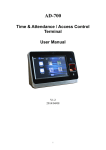
In tunnel mode, the entire original IP packet—payload and header—is encapsulated within
another IP payload, and a new header is appended to it, as shown in Figure 1 on page 13.
The entire original packet can be encrypted, authenticated, or both. With the
Authentication Header (AH) protocol, the AH and new headers are also authenticated.
With the Encapsulating Security Payload (ESP) protocol, the ESP header can also be
authenticated.
Figure 1: Tunnel Mode
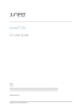
In a site-to-site VPN, the source and destination addresses used in the new header are
the IP addresses of the outgoing interface. See Figure 2 on page 14.
Copyright © 2014, Juniper Networks, Inc.
13
IPsec for Security Devices
Figure 2: Site-to-Site VPN in Tunnel Mode
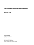
In a dial-up VPN, there is no tunnel gateway on the VPN dial-up client end of the tunnel;
the tunnel extends directly to the client itself (see Figure 3 on page 15). In this case, on
packets sent from the dial-up client, both the new header and the encapsulated original
header have the same IP address: that of the client’s computer.
NOTE: Some VPN clients, such as the dynamic VPN client and
Netscreen-Remote, use a virtual inner IP address (also called a “sticky
address”). Netscreen-Remote enables you to define the virtual IP address.
The dynamic VPN client uses the virtual IP address assigned during the XAuth
configuration exchange. In such cases, the virtual inner IP address is the
source IP address in the original packet header of traffic originating from the
client, and the IP address that the ISP dynamically assigns the dial-up client
is the source IP address in the outer header.
14
Copyright © 2014, Juniper Networks, Inc.
Chapter 2: IP Security
Figure 3: Dial-Up VPN in Tunnel Mode
IKE Packet Processing
When a cleartext packet arrives on a Juniper Networks device that requires tunneling,
and no active Phase 2 SA exists for that tunnel, Junos OS begins IKE negotiations and
drops the packet. The source and destination addresses in the IP packet header are those
of the local and remote IKE gateways, respectively. In the IP packet payload, there is a
UDP segment encapsulating an ISAKMP (IKE) packet. The format for IKE packets is the
same for Phase 1 and Phase 2. See Figure 4 on page 16.
Meanwhile, the source host has sent the dropped packet again. Typically, by the time
the second packet arrives, IKE negotiations are complete, and Junos OS protects the
packet and all subsequent packets in the session—with IPsec before forwarding it.
Copyright © 2014, Juniper Networks, Inc.
15
IPsec for Security Devices
Figure 4: IKE Packet for Phases 1 and 2
The Next Payload field contains a number indicating one of the following payload types:
16
•
0002—SA Negotiation Payload contains a definition for a Phase 1 or Phase 2 SA.
•
0004—Proposal Payload can be a Phase 1 or Phase 2 proposal.
•
0008—Transform Payload gets encapsulated in a proposal payload that gets
encapsulated in an SA payload.
•
0010—Key Exchange (KE) Payload contains information necessary for performing a
key exchange, such as a DH public value.
Copyright © 2014, Juniper Networks, Inc.
Chapter 2: IP Security
•
0020—Identification (IDx) Payload.
•
In Phase 1, IDii indicates the initiator ID, and IDir indicates the responder ID.
•
In Phase 2, IDui indicates the user initiator, and IDur indicates the user responder.
The IDs are IKE ID types such as FQDN, U-FQDN, IP address, and ASN.1_DN.
•
0040—Certificate (CERT) Payload.
•
0080—Certificate Request (CERT_REQ) Payload.
•
0100—Hash (HASH) Payload contains the digest output of a particular hash function.
•
0200—Signature (SIG) Payload contains a digital signature.
•
0400—Nonce (Nx) Payload contains some pseudorandom information necessary for
the exchange).
•
0800—Notify Payload.
•
1000—ISAKMP Delete Payload.
•
2000—Vendor ID (VID) Payload can be included anywhere in Phase 1 negotiations.
Junos OS uses it to mark support for NAT-T.
Each ISAKMP payload begins with the same generic header, as shown in
Figure 5 on page 17.
Figure 5: Generic ISAKMP Payload Header
There can be multiple ISAKMP payloads chained together, with each subsequent payload
type indicated by the value in the Next Header field. A value of 0000 indicates the last
ISAKMP payload. See Figure 6 on page 18 for an example.
Copyright © 2014, Juniper Networks, Inc.
17
IPsec for Security Devices
Figure 6: ISAKMP Header with Generic ISAKMP Payloads
IPsec Packet Processing
After IKE negotiations complete and the two IKE gateways have established Phase 1 and
Phase 2 security associations (SAs), all subsequent packets are forwarded using the
tunnel. If the Phase 2 SA specifies the Encapsulating Security Protocol (ESP) in tunnel
mode, the packet looks like the one shown in Figure 7 on page 18. The device adds two
additional headers to the original packet that the initiating host sends.
NOTE: For information about ESP, see “ESP Protocol” on page 10. For
information about tunnel mode, see “Packet Processing in Tunnel Mode” on
page 13.
As shown in Figure 7 on page 18, the packet that the initiating host constructs includes
the payload, the TCP header, and the inner IP header (IP1).
Figure 7: IPsec Packet—ESP in Tunnel Mode
The router IP header (IP2), which Junos OS adds, contains the IP address of the remote
gateway as the destination IP address and the IP address of the local router as the source
IP address. Junos OS also adds an ESP header between the outer and inner IP headers.
18
Copyright © 2014, Juniper Networks, Inc.
Chapter 2: IP Security
The ESP header contains information that allows the remote peer to properly process
the packet when it receives it. This is shown in Figure 8 on page 19.
Figure 8: Outer IP Header (IP2) and ESP Header
The Next Header field indicates the type of data in the payload field. In tunnel mode, this
value is 4, indicating an IP packet is contained within the payload. See Figure 9 on page 20.
Copyright © 2014, Juniper Networks, Inc.
19
IPsec for Security Devices
Figure 9: Inner IP Header (IP1) and TCP Header
Inner IP Header (IP1)
Version
Header
Type of Service
Total Packet Length (in Bytes)
O D M
Identification
Time to Live (TTL)
Protocol (6 for TCP)
Fragment Offset
Header Checksum
Source Address (Installing Host)
Destination Address (Receiving Host)
Padding
IP Options (if any)
Payload
TCP Header
Destination Port
Source Port
Sequence Number
Acknowledgement Number
Header
Length
Reserved
U A P R S F
R C S S Y I
G K H T N N
Checksum
Window Size
Urgent Pointer
Padding
g030688
IP Options (if any)
Data
Related
Documentation
•
Junos OS Feature Support Reference for SRX Series and J Series Devices
•
VPN Overview on page 5
•
Understanding Phase 1 of IKE Tunnel Negotiation on page 20
•
Understanding Phase 2 of IKE Tunnel Negotiation on page 22
•
Understanding Hub-and-Spoke VPNs on page 33
•
Example: Configuring a Policy-Based VPN on page 115
•
Example: Configuring a Route-Based VPN on page 51
Understanding Phase 1 of IKE Tunnel Negotiation
Phase 1 of an AutoKey Internet Key Exchange (IKE) tunnel negotiation consists of the
exchange of proposals for how to authenticate and secure the channel. The participants
exchange proposals for acceptable security services such as:
20
Copyright © 2014, Juniper Networks, Inc.
Chapter 2: IP Security
•
Encryption algorithms—Data Encryption Standard (DES), triple Data Encryption
Standard (3DES), and Advanced Encryption Standard (AES). (See “IPsec Security
Protocols” on page 9.)
•
Authentication algorithms—Message Digest 5 (MD5 ) and Secure Hash Algorithm
(SHA-1). (See “IPsec Security Protocols” on page 9.)
•
Diffie-Hellman (DH) group. (See “Diffie-Hellman Exchange” on page 9.)
•
Preshared key or RSA/DSA certificates. (See “IPsec Key Management” on page 8.)
A successful Phase 1 negotiation concludes when both ends of the tunnel agree to accept
at least one set of the Phase 1 security parameters proposed and then process them.
Juniper Networks devices support up to four proposals for Phase 1 negotiations, allowing
you to define how restrictive a range of security parameters for key negotiation you will
accept.
Junos OS provides the following predefined Phase 1 proposals:
•
Standard—pre-g2-aes128-sha and pre-g2-3des-sha
•
Compatible—pre-g2-3des-sha, pre-g2-3des-md5, pre-g2-des-sha, and pre-g2-des-md5
•
Basic—pre-g1-des-sha and pre-g1-des-md5
You can also define custom Phase 1 proposals.
Phase 1 exchanges can take place in either main mode or aggressive mode. You can
choose your mode during IKE policy configuration.
This topic includes the following sections:
•
Main Mode on page 21
•
Aggressive Mode on page 22
Main Mode
In main mode, the initiator and recipient send three two-way exchanges (six messages
total) to accomplish the following services:
•
First exchange (messages 1 and 2)—Proposes and accepts the encryption and
authentication algorithms.
•
Second exchange (messages 3 and 4)—Executes a DH exchange, and the initiator and
recipient each provide a pseudorandom number.
•
Third exchange (messages 5 and 6)—Sends and verifies the identities of the initiator
and recipient.
The information transmitted in the third exchange of messages is protected by the
encryption algorithm established in the first two exchanges. Thus, the participants’
identities are encrypted and therefore not transmitted “in the clear.”
Copyright © 2014, Juniper Networks, Inc.
21
IPsec for Security Devices
Aggressive Mode
In aggressive mode, the initiator and recipient accomplish the same objectives as with
main mode, but in only two exchanges, with a total of three messages:
•
First message—The initiator proposes the security association (SA), initiates a DH
exchange, and sends a pseudorandom number and its IKE identity.
•
Second message—The recipient accepts the SA; authenticates the initiator; and sends
a pseudorandom number, its IKE identity, and, if using certificates, the recipient's
certificate.
•
Third message—The initiator authenticates the recipient, confirms the exchange, and,
if using certificates, sends the initiator's certificate.
Because the participants’ identities are exchanged in the clear (in the first two messages),
aggressive mode does not provide identity protection.
NOTE: When a dial-up VPN user negotiates an AutoKey IKE tunnel with a
preshared key, aggressive mode must be used. Therefore, you must always
use aggressive mode with the dynamic VPN feature. Note also that a dial-up
VPN user can use an e-mail address, a fully qualified domain name (FQDN),
or an IP address as its IKE ID. A dynamic peer can use either an e-mail address
or an FQDN, but not an IP address.
Related
Documentation
•
Junos OS Feature Support Reference for SRX Series and J Series Devices
•
VPN Overview on page 5
•
Understanding Phase 2 of IKE Tunnel Negotiation on page 22
•
Example: Configuring a Policy-Based VPN on page 115
•
Example: Configuring a Route-Based VPN on page 51
Understanding Phase 2 of IKE Tunnel Negotiation
After the participants have established a secure and authenticated channel, they proceed
through Phase 2, in which they negotiate security associations (SAs) to secure the data
to be transmitted through the IPsec tunnel.
Similar to the process for Phase 1, the participants exchange proposals to determine
which security parameters to employ in the SA. A Phase 2 proposal also includes a security
protocol—either Encapsulating Security Payload (ESP) or Authentication Header
(AH)—and selected encryption and authentication algorithms. The proposal can also
specify a Diffie-Hellman (DH) group, if Perfect Forward Secrecy (PFS) is desired.
Regardless of the mode used in Phase 1, Phase 2 always operates in quick mode and
involves the exchange of three messages.
22
Copyright © 2014, Juniper Networks, Inc.
Chapter 2: IP Security
Juniper Networks devices support up to four proposals for Phase 2 negotiations, allowing
you to define how restrictive a range of tunnel parameters you will accept. Junos OS
provides the following predefined Phase 2 proposals:
•
Standard—g2-esp-3des-sha and g2-esp-aes128-sha
•
Compatible—nopfs-esp-3des-sha, nopfs-esp-3des-md5, nopfs-esp-des-sha, and
nopfs-esp-des-md5
•
Basic—nopfs-esp-des-sha and nopfs-esp-des-md5
You can also define custom Phase 2 proposals.
This topic includes the following sections:
•
Proxy IDs on page 23
•
Perfect Forward Secrecy on page 23
•
Replay Protection on page 23
Proxy IDs
In Phase 2, the peers exchange proxy IDs. A proxy ID consists of a local and remote IP
address prefix. The proxy ID for both peers must match, which means that the local IP
address specified for one peer must be the same as the remote IP address specified for
the other peer.
Perfect Forward Secrecy
PFS is a method for deriving Phase 2 keys independent from and unrelated to the
preceding keys. Alternatively, the Phase 1 proposal creates the key (the SKEYID_d key)
from which all Phase 2 keys are derived. The SKEYID_d key can generate Phase 2 keys
with a minimum of CPU processing. Unfortunately, if an unauthorized party gains access
to the SKEYID_d key, all your encryption keys are compromised.
PFS addresses this security risk by forcing a new DH key exchange to occur for each
Phase 2 tunnel. Using PFS is thus more secure, although the rekeying procedure in Phase 2
might take slightly longer with PFS enabled.
Replay Protection
A replay attack occurs when an unauthorized person intercepts a series of packets and
uses them later either to flood the system, causing a denial of service (DoS), or to gain
entry to the trusted network. Junos OS provides a replay protection feature that enables
devices to check every IPsec packet to see if it has been received previously. If packets
arrive outside a specified sequence range, Junos OS rejects them. Use of this feature
does not require negotiation, because packets are always sent with sequence numbers.
You simply have the option of checking or not checking the sequence numbers.
Related
Documentation
•
Junos OS Feature Support Reference for SRX Series and J Series Devices
•
VPN Overview on page 5
•
Example: Configuring a Policy-Based VPN on page 115
Copyright © 2014, Juniper Networks, Inc.
23
IPsec for Security Devices
•
Example: Configuring a Route-Based VPN on page 51
Understanding Internet Key Exchange Version 2
Internet Key Exchange Version 2 (IKEv2) is the next generation standard for secure key
exchange between peer devices, defined in RFC 4306. IKEv2 is available in this release
for securing IPsec traffic.
The gateway configuration is used to distinguish between IKEv1 and IKEv2. A remote peer
is configured as either IKEv1 or IKEv2. When a peer is configured as IKEv2, it cannot fall
back to IKEv1 if the peer initiates IKEv1 negotiation. The default value for the version is
"v1-only". The version "v2-only" is supported from Junos OS Release 11.3 onward.
Use the version configuration statement at the edit security ike gateway gw-name hierarchy
level to configure IKEv2. To view the version information in the CLI, enter the following
commands:
•
user@host>show security ike security-associations
•
user@host>show security ipsec security-associations
The advantages of using version 2 over version 1 are as follows;
•
Simplifies the existing IKEv1
•
Single RFC, including NAT-T, EAP and remote address acquisition
•
Replaces the 8 initial exchanges with a single 4 message exchange
•
Reduces the latency for the IPSEC SA setup and increases connection establishment
speed.
•
Increases robustness against DOS attack.
•
Improves reliability through the use of sequence numbers, acknowledgements, and
error correction.
•
Forward Compatibility
•
Simple cryptographic mechanisms
•
Traffic selector negotiation:
•
•
IKEv1: Responder can just say yes/no
•
IKEv2: Negotiation ability added
Reliability
•
All messages are request/response.
•
Initiator is responsible for retransmission if it doesn’t receive a response.
IKEv2 includes support for:
24
Copyright © 2014, Juniper Networks, Inc.
Chapter 2: IP Security
Related
Documentation
•
Route-based VPN
•
Site-to-site VPN
•
Dead peer detection (liveness check)
•
Chassis cluster
•
Certificate-based authentication
•
Hardware offloading of the ModExp operations in a Diffie Hellman (DH) exchange
•
Traffic selectors—An IKEv2 traffic selector is essentially the same as an IKEv1 Proxy-ID.
Traffic selectors and proxy-IDs are used the same way. IKEv2 specifies single traffic
selector in each direction.
•
An IKEv2 child SA is known as a Phase 2 SA in IKEv1. The child SA differs in behavior
from the Phase 2 SA in the following ways:
•
IKE and child SA rekeying—In IKEv2, a child security association (SA) cannot exist
without the underlying IKE SA. If a child SA is required, it will be rekeyed; however, if
the child SAs are currently active, the corresponding IKE SA will be rekeyed.
•
Version 1 and version 2
•
Example: Configuring a Route-Based VPN for IKEv2 on page 69
Copyright © 2014, Juniper Networks, Inc.
25
IPsec for Security Devices
26
Copyright © 2014, Juniper Networks, Inc.
CHAPTER 3
Route-Based VPN
•
Understanding Route-Based IPsec VPNs on page 27
•
Understanding Virtual Router Limitations on page 28
•
Virtual Router Support for Route-Based VPNs on page 28
Understanding Route-Based IPsec VPNs
With route-based VPNs, you can configure dozens of security policies to regulate traffic
flowing through a single VPN tunnel between two sites, and there is just one set of IKE
and IPsec SAs at work. Unlike policy-based VPNs, for route-based VPNs, a policy refers
to a destination address, not a VPN tunnel. When Junos OS looks up a route to find the
interface to use to send traffic to the packet’s destination address, it finds a route through
a secure tunnel interface (st0.x). The tunnel interface is bound to a specific VPN tunnel,
and the traffic is routed to the tunnel if the policy action is permit.
Examples of where route-based VPNs can be used:
•
There are overlapping subnets or IP addresses between the two LANs.
•
A hub-and-spoke VPN topology is used in the network, and spoke-to-spoke traffic is
required.
•
Primary and backup VPNs are required.
•
A dynamic routing protocol (for example, OSPF, RIP, or BGP) is running across the
VPN.
NOTE: We recommend that you use route-based VPN when you want to
configure VPN between multiple remote sites. Route-based VPN allows for
routing between the spokes between multiple remote sites; it is easier to
configure, monitor, and troubleshoot.
Use policy-based VPN when your topology has a third-party device and
requires a separate SAs for each remote subnet.
Related
Documentation
•
Junos OS Feature Support Reference for SRX Series and J Series Devices
•
VPN Overview on page 5
Copyright © 2014, Juniper Networks, Inc.
27
IPsec for Security Devices
•
Example: Configuring a Hub-and-Spoke VPN on page 161
•
Example: Configuring a Policy-Based VPN on page 115
Understanding Virtual Router Limitations
The following features are not supported in this release for virtual router (VR):
Related
Documentation
•
Dynamic endpoint VPN and remote access VPN inside VR
•
Public key infrastructure (PKI) inside VR
•
Chassis cluster active/active with VPN inside VR
•
Junos OS Feature Support Reference for SRX Series and J Series Devices
•
Virtual Router Support for Route-Based VPNs on page 28
Virtual Router Support for Route-Based VPNs
This feature includes routing-instance support for route-based VPNs. In previous releases,
when an st0 interface was put in a nondefault routing instance, the VPN tunnels on this
interface did not work properly. In the Junos OS 10.4 release, the support is enabled to
place st0 interfaces in a routing instance, where each unit is configured in point-to-point
mode or multipoint mode. Therefore, VPN traffic now works correctly in a nondefault
VR. You can now configure different subunits of the st0 interface in different routing
instances. The following functions are supported for nondefault routing instances:
28
•
Manual key management
•
Transit traffic
•
Self-traffic
•
VPN monitoring
•
Hub-and-spoke VPNs
•
Encapsulating Security Payload (ESP) protocol
•
Authentication Header (AH) protocol
•
Aggressive mode or main mode
•
st0 anchored on the loopback (lo0) interface
•
Maximum number of virtual routers (VRs) supported on an SRX Series device
•
Applications such as Application Layer Gateway (ALG), Intrusion Detection and
Prevention (IDP), and Unified Threat Management (UTM)
•
Dead peer detection (DPD)
•
Chassis cluster active/backup
•
Open Shortest Path First (OSPF) over st0
Copyright © 2014, Juniper Networks, Inc.
Chapter 3: Route-Based VPN
Related
Documentation
•
Routing Information Protocol (RIP) over st0
•
Policy-based VPN inside VR
•
Junos OS Feature Support Reference for SRX Series and J Series Devices
•
Understanding Virtual Router Limitations on page 28
Copyright © 2014, Juniper Networks, Inc.
29
IPsec for Security Devices
30
Copyright © 2014, Juniper Networks, Inc.
CHAPTER 4
Policy-Based VPN
•
Understanding Policy-Based IPsec VPNs on page 31
Understanding Policy-Based IPsec VPNs
For policy-based IPsec VPNs, a security policy specifies as its action the VPN tunnel to
be used for transit traffic that meets the policy’s match criteria. A VPN is configured
independent of a policy statement. The policy statement refers to the VPN by name to
specify the traffic that is allowed access to the tunnel. For policy-based VPNs, each policy
creates an individual IPsec security association (SA) with the remote peer, each of which
counts as an individual VPN tunnel. For example, if a policy contains a group source
address and a group destination address, whenever one of the users belonging to the
address set attempts to communicate with any one of the hosts specified as the
destination address, a new tunnel is negotiated and established. Because each tunnel
requires its own negotiation process and separate pair of SAs, the use of policy-based
IPsec VPNs can be more resource-intensive than route-based VPNs.
Examples of where policy-based VPNs can be used:
•
You are implementing a dial-up VPN.
•
You require more granularity than a route can provide when determining which traffic
is sent to a tunnel (for example, you need to specify that traffic to a certain destination
goes through the tunnel only if the traffic originated from a particular source).
•
The remote VPN device is a non-Juniper device that requires separate SAs for each
remote subnet.
NOTE: We recommend that you use route-based VPN when you want to
configure VPN between multiple remote sites. Route-based VPN allows for
routing between the spokes between multiple remote sites; it is easier to
configure, monitor, and troubleshoot.
Use policy-based VPN when your topology has a third-party device and
requires a separate SAs for each remote subnet.
Related
Documentation
•
Junos OS Feature Support Reference for SRX Series and J Series Devices
Copyright © 2014, Juniper Networks, Inc.
31
IPsec for Security Devices
32
•
VPN Overview on page 5
•
Example: Configuring a Route-Based VPN on page 51
•
Example: Configuring a Hub-and-Spoke VPN on page 161
•
Example: Configuring a Policy-Based VPN on page 115
Copyright © 2014, Juniper Networks, Inc.
CHAPTER 5
Hub-and-Spoke VPN
•
Understanding Hub-and-Spoke VPNs on page 33
Understanding Hub-and-Spoke VPNs
If you create two VPN tunnels that terminate at a device, you can set up a pair of routes
so that the device directs traffic exiting one tunnel to the other tunnel. You also need to
create a policy to permit the traffic to pass from one tunnel to the other. Such an
arrangement is known as hub-and-spoke VPN. (See Figure 10 on page 33.)
You can also configure multiple VPNs and route traffic between any two tunnels.
NOTE: SRX Series devices support only the route-based hub-and-spoke
feature.
Figure 10: Multiple Tunnels in a Hub-and-Spoke VPN Configuration
Related
Documentation
•
Junos OS Feature Support Reference for SRX Series and J Series Devices
•
VPN Overview on page 5
•
Example: Configuring a Hub-and-Spoke VPN on page 161
Copyright © 2014, Juniper Networks, Inc.
33
IPsec for Security Devices
34
Copyright © 2014, Juniper Networks, Inc.
CHAPTER 6
NAT Traversal
•
Understanding NAT-T on page 35
Understanding NAT-T
Network Address Translation-Traversal (NAT-T) is a method for getting around IP address
translation issues encountered when data protected by IPsec passes through a NAT
device for address translation. Any changes to the IP addressing, which is the function
of NAT, causes IKE to discard packets. After detecting one or more NAT devices along
the data path during Phase 1 exchanges, NAT-T adds a layer of User Datagram Protocol
(UDP) encapsulation to IPsec packets so they are not discarded after address translation.
Junos OS implements NAT-T one-to-one IP addressing (static NAT) when a NAT device
is located along a VPN data path, such as in route-based, policy-based, and
hub-and-spoke topologies. The location of a NAT device can be such that:
•
Only the initiator is behind a NAT device.
•
Initiators connect through multiple NAT devices to the responder.
•
Initiators are behind separate NAT devices.
•
Only the responder is behind a NAT device.
•
Both the initiator and the responder are behind a NAT device.
Configuration examples for NAT-T are provided for the topology in which only the
responder is behind a NAT device and the topology in which both the initiator and
responder are behind a NAT device. Site-to-site IKE gateway configuration for NAT-T is
supported on both the initiator and responder. A remote IKE ID is used to validate a peer’s
local IKE ID during Phase 1 of IKE tunnel negotiation. Both the initiator and responder
require a local-identity and a remote-identity setting.
All the VPN topologies use the following hardware:
•
SRX Series Services Gateways
•
J Series Services Routers
Copyright © 2014, Juniper Networks, Inc.
35
IPsec for Security Devices
NOTE: If SRX Series hardware is used as a responder, when you upgrade
to the current Junos OS release, you must upgrade the responder first, then
configure local-identity before upgrading the initiator. This approach is
required in case of a Dynamic End Point (DEP) scenario, in which an ID type
is used instead of an IP address. If the responder is not upgraded first, and
a NAT device is added in front of an SRX Series responder, then the initiator
hardware must be configured such that remote-identity is the responder’s
private IP address.
Related
Documentation
36
•
Junos OS Feature Support Reference for SRX Series and J Series Devices
•
VPN Overview on page 5
•
Example: Configuring a Route-Based VPN with Only the Responder Behind a NAT
Device on page 85
•
Example: Configuring a Policy-Based VPN with Both an Initiator and a Responder
Behind a NAT Device on page 132
Copyright © 2014, Juniper Networks, Inc.
CHAPTER 7
VPN Alarms
•
Understanding VPN Alarms and Auditing on page 37
Understanding VPN Alarms and Auditing
Configure the following command to enable security event logging during the initial set
up of the device.
set security log cache
The administrators (audit, cryptographic, IDS and security) cannot modify the security
event logging configuration if the above command is configured and each administrator
role is configured to have a distinct, unique set of privileges apart from all other
administrative roles.
Alarms are triggered by a VPN failure. A VPN alarm is generated when the system monitors
any of the following audited events:
•
Authentication failures—You can configure the device to generate a system alarm when
the packet authentication failures reaches a specified number.
•
Encryption and decryption failures—You can configure the device to generate a system
alarm when encryption or decryption failures exceed a specified number.
•
IKE Phase 1 and IKE Phase 2 failures—Internet Key Exchange (IKE) Phase 1 negotiations
are used to establish IKE security associations (SAs). These SAs protect the IKE Phase
2 negotiations. You can configure the device to generate a system alarm when IKE
Phase 1 or IKE Phase 2 failures exceed a specified number.
•
Self-test failures—Self tests are tests that a device runs upon power on or reboot to
verify whether security software is implemented correctly on your device.
Self-tests ensure the correctness of cryptographic algorithms. The JUNOS-FIPS image
performs self-tests automatically upon power-on, and continuously for key-pair
generation. In either domestic or FIPS images, self-tests may be configured to be
performed according to a defined schedule, upon demand or immediately after key
generation.
You can configure the device to generate a system alarm when a self-test failure occurs.
•
IDP flow policy attacks—An intrusion detection and prevention (IDP) policy allows you
to enforce various attack detection and prevention techniques on network traffic. You
Copyright © 2014, Juniper Networks, Inc.
37
IPsec for Security Devices
can configure the device to generate a system alarm when IDP flow policy violations
occur.
•
Replay attacks—A replay attack is a network attack in which a valid data transmission
is maliciously or fraudulently repeated or delayed. You can configure the device to
generate a system alarm when a replay attack occurs.
The syslog messages are included in the following cases:
•
Failed symmetric key generation
•
Failed asymmetric key generation
•
Failed manual key distribution
•
Failed automated key distribution
•
Failed key destruction
•
Failed key handling and storage
•
Failed data encryption or decryption
•
Failed signature
•
Failed key agreement
•
Failed cryptographic hashing
•
IKE failure
•
Failed authentication of the received packets
•
Decryption error due to invalid padding content
•
Mismatch in the length specified in the alternative subject field of the certificate received
from a remote VPN peer device.
Alarms are raised based on syslog messages. Every failure is logged, but an alarm is
generated only when a threshold is reached.
To view the alarm information, run the show security alarms command. The violation
count and the alarm do not persist across system reboots. After a reboot, the violation
count resets to zero, and the alarm is cleared from the alarm queue.
After appropriate actions have been taken, you can clear the alarm. The alarm remains
in the queue until you clear it (or until you reboot the device). To clear the alarm, run the
clear security alarms command.
Related
Documentation
38
•
Junos OS Feature Support Reference for SRX Series and J Series Devices
•
Example: Setting an Audible Alert as Notification of a Security Alarm on page 215
•
Example: Generating Security Alarms in Response to Potential Violations on page 216
Copyright © 2014, Juniper Networks, Inc.
CHAPTER 8
IPv6 IPsec
•
Understanding IPv6 IKE and IPsec Packet Processing on page 39
Understanding IPv6 IKE and IPsec Packet Processing
An IPv6 IPsec VPN implementation involves the exchange of IPv6 packets within an IPv6
tunnel set up between two IPv6 tunnel endpoints. (See “VPN Overview” on page 5.)
This topic includes the following sections:
•
Packet Processing in IPv6 6in6 Tunnel Mode on page 39
•
IPv6 IKE Packet Processing on page 39
•
IPv6 IPsec Packet Processing on page 41
Packet Processing in IPv6 6in6 Tunnel Mode
IPv6 VPN 6in6 tunneling is a technique for exchanging IPv6 packets within an IPv6 IPsec
tunnel between two site-to-site endpoints. In this mode, the original IPv6 packet is
encapsulated inside another IPv6 packet where both the outer and inner headers are
IPv6. The IPv6 addresses of the outer IPv6 header represent the tunnel endpoints, while
the IPv6 addresses of the inner IPv6 header represent the final source and destination
addresses. Unlike the transport mode, where the original IP header is retained, in the 6in6
tunneling mode, the entire original IPv6 packet (payload and header) is encapsulated
by appending a new outer IPv6 header, IPsec headers (AH or ESP), followed by the inner
IPv6 header, and the original IPv6 payload. The entire original IPv6 packet can be
encrypted, authenticated, or both. The Authentication Header (AH) protocol provides
authentication, while the Encapsulation Security Payload (ESP) protocol provides
encryption as well as authentication for the IPv6 packets.
IPv6 IKE Packet Processing
Internet Key Exchange (IKE) is part of the IPsec suite of protocols. It automatically enables
two tunnel endpoints to set up security associations (SAs) and negotiate secret keys
with each other. There is no need to manually configure the security parameters. IKE also
provides authentication for communicating peers.
IKE packet processing in IPv6 networks involves the following elements:
•
ISAKMP Identification Payload
Copyright © 2014, Juniper Networks, Inc.
39
IPsec for Security Devices
Internet Security Association and Key Management Protocol (ISAKMP) identification
payload is used to identify and authenticate the communicating IPv6 peers. Two new
ID types—ID_IPV6_ADDR and ID_IPV6_ADDR_SUBNET—are enabled for IPv6. The ID
type indicates the type of identification to be used. The ID_IPV6_ADDR type specifies
a single 16-octet IPv6 address. This ID type represents an IPv6 address. The
ID_IPV6_ADDR_SUBNET type specifies a range of IPv6 addresses represented by two
16-octet values. This ID type represents an IPv6 network mask. Table 5 on page 40
lists the ID types and their assigned values in the identification payload.
Table 5: ISAKMP ID Types and Their Values
ID Type
Value
RESERVED
0
ID_IPV4_ADDR
1
ID_FQDN
2
ID_USER_FQDN
3
ID_IPV4_ADDR_SUBNET
4
ID_IPV6_ADDR
5
ID_IPV6_ADDR_SUBNET
6
ID_IPV4_ADDR_RANGE
7
ID_IPV6_ADDR_RANGE
8
ID_DER_ASN1_DN
9
ID_DER_ASN1_GN
10
ID_KEY_ID
11
ID_LIST
12
The ID_IPV6_ADDR_RANGE type specifies a range of IPv6 addresses represented by
two 16-octet values. The first octet value represents the starting IPv6 address and the
second octet value represents the ending IPv6 address in the range. All IPv6 addresses
falling between the first and last IPv6 addresses are considered to be part of the list.
NOTE: Two ID types in ISAKMP identification
payload—ID_IPV6_ADDR_RANGE and ID_IPV4_ADDR_RANGE—are not
supported in this release.
•
40
Proxy ID
Copyright © 2014, Juniper Networks, Inc.
Chapter 8: IPv6 IPsec
A proxy ID is used during Phase 2 of IKE negotiation. It is generated before an IPsec
tunnel is established. A proxy ID identifies the SA to be used for the VPN. Two proxy
IDs are generated—local and remote. The local proxy ID refers to the local IPv6
address/network and subnet mask. The remote proxy ID refers to the remote IPv6
address/network and subnet mask.
•
Security Association
An SA is an agreement between VPN participants to support secure communication.
SAs are differentiated based on three parameters—security parameter index (SPI),
destination IPv6 address, and security protocol (either AH or ESP). The SPI is a unique
value assigned to an SA to help identify an SA among multiple SAs. In an IPv6 packet,
the SA is identified from the destination address in the outer IPv6 header and the
security protocol is identified from either the AH or the ESP header.
IPv6 IPsec Packet Processing
After IKE negotiations are completed and the two IKE gateways have established Phase
1 and Phase 2 security associations (SAs), IPv6 IPsec employs authentication and
encryption technologies to secure the IPv6 packets.
This topic includes the following sections:
•
AH Protocol in IPv6 on page 41
•
ESP Protocol in IPv6 on page 41
•
Integrity Check Value (ICV) Calculation in IPv6 on page 42
•
Header Construction in IPv6 Tunnel Mode on page 42
AH Protocol in IPv6
The AH protocol provides data integrity and data authentication for IPv6 packets. IPv6
IPsec uses extension headers (for example, hop-by-hop and routing options) that must
be arranged in a particular way in the IPv6 datagram. In IPv6 AH tunnel mode, the AH
header immediately follows the new outer IPv6 header similar to that in IPv4 AH tunnel
mode. The extension headers are placed after the original inner IPv6 header. Therefore,
in IPv6 AH tunnel mode, the entire IPv6 packet is encapsulated by adding a new outer
IPv6 header, followed by an authentication header, an inner IPv6 header, extension
headers, and the rest of the original IPv6 datagram as shown in Figure 11 on page 41.
Figure 11: IPv6 AH Tunnel Mode
ESP Protocol in IPv6
ESP protocol provides both encryption and authentication for IPv6 packets. Because
IPv6 IPsec uses extension headers (for example, hop-by-hop and routing options) in the
IPv6 datagram, the most important difference between IPv6 ESP tunnel mode and IPv4
Copyright © 2014, Juniper Networks, Inc.
41
IPsec for Security Devices
ESP tunnel mode is the placement of extension headers in the packet layout. In IPv6 ESP
tunnel mode, the ESP header immediately follows the new outer IPv6 header similar to
that in IPv4 ESP tunnel mode. Therefore, in IPv6 ESP tunnel mode, the entire IPv6 packet
is encapsulated by adding a new outer IPv6 header, followed by an ESP header, an inner
IPv6 header, extension headers, and the rest of the original IPv6 datagram as shown in
Figure 12 on page 42.
Figure 12: IPv6 ESP Tunnel Mode
Integrity Check Value (ICV) Calculation in IPv6
AH protocol verifies the integrity of the IPv6 packet by computing an Integrity Check
Value (ICV) on the packet contents. ICV is usually built over an authentication algorithm
such as MD5 or SHA-1. The IPv6 ICV calculations differ from that in IPv4 in terms of two
header fields—mutable header and optional extension header.
You can calculate the AH ICV over the IPv6 header fields that are either immutable in
transit or predictable in value upon arrival at the tunnel endpoints. You can also calculate
the AH ICV over the AH header and the upper level protocol data (considered to be
immutable in transit). You can calculate the ESP ICV over the entire IPv6 packet, excluding
the new outer IPv6 header and the optional extension headers.
NOTE: Unlike IPv4, IPv6 has a method for tagging options as mutable in
transit. IPv6 optional extension headers contain a flag that indicates
mutability. This flag determines the appropriate processing.
Header Construction in IPv6 Tunnel Mode
In IPv6 tunnel mode, the source and destination addresses of the outer IPv6 header
represent the tunnel endpoints, while the source and destination addresses of the inner
IPv6 header represent the final source and destination addresses. Table 6 on page 42
summarizes the differences between the outer IPv6 header and the inner IPv6 header.
Table 6: Comparison Between Outer Headers and Inner Headers
Header Fields
Outer Header
Inner Header
version
6
No change.
DS field
Copied from the inner header.
No change.
ECN field
Copied from the inner header.
Constructed.
42
Copyright © 2014, Juniper Networks, Inc.
Chapter 8: IPv6 IPsec
Table 6: Comparison Between Outer Headers and Inner Headers (continued)
Header Fields
Outer Header
Inner Header
flow label
Copied from the inner header.
No change.
payload length
Constructed.
No change.
next header
AH, ESP, and routing header.
No change.
hop limit
64.
Decrement.
src address
Constructed.
No change.
dest address
Constructed.
No change.
extension headers
Never copied.
No change.
NOTE: This release supports IPv6 6in6 site-to-site VPN only. The IPv6 6in6
site-to-site VPN uses IPv6 address as the IKE identity in this release.
Related
Documentation
•
Junos OS Feature Support Reference for SRX Series and J Series Devices
•
VPN Overview on page 5
•
IPv6 IPsec Configuration Overview on page 195
•
Example: Configuring an IPv6 IPsec Manual VPN on page 196
•
Example: Configuring an IPv6 AutoKey IKE Policy-Based VPN on page 198
Copyright © 2014, Juniper Networks, Inc.
43
IPsec for Security Devices
44
Copyright © 2014, Juniper Networks, Inc.
CHAPTER 9
Global SPI and VPN Monitoring
•
Understanding Global SPI and VPN Monitoring Features on page 45
Understanding Global SPI and VPN Monitoring Features
You can monitor and maintain the efficient operation of your VPN using the following
global VPN features:
Related
Documentation
•
SPI—Peers in a security association (SA) can become unsynchronized when one of
the peers fails. For example, if one of the peers reboots, it might send an incorrect
security parameter index (SPI). You can enable the device to detect such an event and
resynchronize the peers by configuring the bad SPI response feature.
•
VPN monitoring—You can use the global VPN monitoring feature to periodically send
Internet Control Message Protocol (ICMP) requests to the peer to determine if the peer
is reachable.
•
Junos OS Feature Support Reference for SRX Series and J Series Devices
•
VPN Overview on page 5
•
Example: Configuring Global SPI and VPN Monitoring Features on page 223
Copyright © 2014, Juniper Networks, Inc.
45
IPsec for Security Devices
46
Copyright © 2014, Juniper Networks, Inc.
PART 2
Configuration
•
IP Security on page 49
•
Route-Based VPN on page 51
•
Policy-Based VPN on page 115
•
Hub-and-Spoke VPN on page 161
•
IPv6 IPsec on page 195
•
VPN Alarms on page 215
•
FIPS Self Tests on page 219
•
Global SPI and VPN Monitoring on page 223
•
Configuration Statements on page 225
Copyright © 2014, Juniper Networks, Inc.
47
IPsec for Security Devices
48
Copyright © 2014, Juniper Networks, Inc.
CHAPTER 10
IP Security
•
Configuring IPsec VPN Using the VPN Wizard on page 49
Configuring IPsec VPN Using the VPN Wizard
The VPN Wizard enables you to perform basic IPsec VPN configuration, including both
Phase 1 and Phase 2. For more advanced configuration, use the J-Web interface or the
CLI.
To configure IPsec VPN using the VPN Wizard:
1.
Select Configure>Wizards>VPN Wizard in the J-Web interface.
2. Click the Launch VPN Wizard button.
3. Follow the wizard prompts.
The upper left area of the wizard page shows where you are in the configuration process.
The lower left area of the page shows field-sensitive help. When you click a link under
the Resources heading, the document opens in your browser. If the document opens in
a new tab, be sure to close only the tab (not the browser window) when you close the
document.
Related
Documentation
•
VPN Overview on page 5
•
Understanding Phase 1 of IKE Tunnel Negotiation on page 20
•
Understanding Phase 2 of IKE Tunnel Negotiation on page 22
Copyright © 2014, Juniper Networks, Inc.
49
IPsec for Security Devices
50
Copyright © 2014, Juniper Networks, Inc.
CHAPTER 11
Route-Based VPN
•
Example: Configuring a Route-Based VPN on page 51
•
Example: Configuring a Route-Based VPN for IKEv2 on page 69
•
Example: Configuring a Route-Based VPN with Only the Responder Behind a NAT
Device on page 85
•
Example: Configuring an st0 Interface in a Virtual Router on page 110
Example: Configuring a Route-Based VPN
This example shows how to configure a route-based IPsec VPN to allow data to be
securely transferred between a branch office and the corporate office.
•
Requirements on page 51
•
Overview on page 51
•
Configuration on page 55
•
Verification on page 64
Requirements
This example uses the following hardware:
•
SRX240 device
•
SSG140 device
Before you begin, read “VPN Overview” on page 5.
Overview
In this example, you configure a route-based VPN for a branch office in Chicago, Illinois,
because you want to conserve tunnel resources but still get granular restrictions on VPN
traffic. Users in the Chicago office will use the VPN to connect to their corporate
headquarters in Sunnyvale, California.
Figure 13 on page 52 shows an example of a route-based VPN topology. In this topology,
the SRX Series device is located in Sunnyvale, and an SSG Series device (or a third-party
device) is located in Chicago.
Copyright © 2014, Juniper Networks, Inc.
51
IPsec for Security Devices
Figure 13: Route-Based VPN Topology
Trust zone
192.168.168.10/24
SSG Series device
e0/6
192.168.168.1/24
Chicago
e0/0
2.2.2.2/30
Untrust
zone
tunnel1
10.11.11.11/24
VPN-chicago zone
Internet
SRX Series device
ge-0/0/3.0
1.1.1.2/30
Sunnyvale
ge-0/0/0.0
10.10.10.1/24
st0.0
10.11.11.10/24
VPN-chicago zone
Trust zone
10.10.10.10/24
In this example, you configure interfaces, an IPv4 default route, security zones, and
address books. Then you configure IKE Phase 1, IPsec Phase 2, security policy, and
TCP-MSS parameters. See Table 7 on page 53 through Table 11 on page 54 for specific
configuration parameters used in this example.
52
Copyright © 2014, Juniper Networks, Inc.
Chapter 11: Route-Based VPN
Table 7: Interface, Static Route, Security Zone, and Address Book Information
Feature
Name
Configuration Parameters
Interfaces
ge-0/0/0.0
10.10.10.1/24
ge-0/0/3.0
1.1.1.2/30
st0.0 (tunnel interface)
10.11.11.10/24
0.0.0.0/0 (default route)
The next hop is 1.1.1.1.
192.168.168.0/24
The next hop is st0.0.
trust
•
All system services are allowed.
•
The ge-0/0/0.0 interface is bound to
this zone.
•
IKE is the only allowed system service.
•
The ge-0/0/3.0 interface is bound to
this zone.
Static routes
Security zones
untrust
Address book entries
vpn-chicago
The st0.0 interface is bound to this zone.
sunnyvale
•
This address is an entry in the address
book book1, which is attached to a zone
called trust.
•
The address for this address book entry
is 10.10.10.0/24.
•
This address is an entry in the address
book book2, which is attached to a zone
called vpn-chicago.
•
The address for this address book entry
is 192.168.168.0/24.
chicago
Table 8: IKE Phase 1 Configuration Parameters
Feature
Name
Configuration Parameters
Proposal
ike-phase1-proposal
•
Authentication method: pre-shared-keys
•
Diffie-Hellman group: group2
•
Authentication algorithm: sha1
•
Encryption algorithm: aes-128-cbc
•
Mode: main
•
Proposal reference: ike-phase1-proposal
•
IKE Phase 1 policy authentication method: pre-shared-key ascii-text
•
IKE policy reference: ike-phase1-policy
•
External interface: ge-0/0/3.0
•
Gateway address: 2.2.2.2
Policy
Gateway
ike-phase1-policy
gw-chicago
Copyright © 2014, Juniper Networks, Inc.
53
IPsec for Security Devices
Table 9: IPsec Phase 2 Configuration Parameters
Feature
Name
Configuration Parameters
Proposal
ipsec-phase2-proposal
•
Protocol: esp
•
Authentication algorithm: hmac-sha1-96
•
Encryption algorithm: aes-128-cbc
•
Proposal reference: ipsec-phase2-proposal
•
PFS: Diffie-Hellman group2
•
IKE gateway reference: gw-chicago
•
IPsec policy reference: ipsec-phase2-policy
•
Bind to interface: st0.0
Policy
VPN
ipsec-phase2-policy
ike-vpn-chicago
Table 10: Security Policy Configuration Parameters
Purpose
Name
Configuration Parameters
The security policy permits traffic from the trust
zone to the vpn-chicago zone.
vpn-tr-chi
•
The security policy permits traffic from the
vpn-chicago zone to the trust zone.
vpn-chi-tr
Match criteria:
•
source-address sunnyvale
•
destination-address chicago
•
application any
•
Action: permit
•
Match criteria:
•
•
source-address chicago
•
destination-address sunnyvale
•
application any
Action: permit
Table 11: TCP-MSS Configuration Parameters
Purpose
Configuration Parameters
TCP-MSS is negotiated as part of the TCP
three-way handshake and limits the maximum
size of a TCP segment to better fit the MTU limits
on a network. For VPN traffic, the IPsec
encapsulation overhead, along with the IP and
frame overhead, can cause the resulting ESP
packet to exceed the MTU of the physical interface,
which causes fragmentation. Fragmentation
increases bandwidth and device resources.
MSS value: 1350
NOTE: We recommend a value of 1350 as the
starting point for most Ethernet-based networks
with an MTU of 1500 or greater. You might need
to experiment with different TCP-MSS values to
obtain optimal performance. For example, you
might need to change the value if any device in the
path has a lower MTU, or if there is any additional
overhead such as PPP or Frame Relay.
54
Copyright © 2014, Juniper Networks, Inc.
Chapter 11: Route-Based VPN
Configuration
•
Configuring Interface, Static Route, Security Zone, and Address Book
Information on page 55
•
Configuring IKE on page 58
•
Configuring IPsec on page 60
•
Configuring Security Policies on page 61
•
Configuring TCP-MSS on page 63
•
Configuring the SSG Series Device on page 63
Configuring Interface, Static Route, Security Zone, and Address Book Information
CLI Quick
Configuration
To quickly configure this section of the example, copy the following commands, paste
them into a text file, remove any line breaks, change any details necessary to match your
network configuration, and then copy and paste the commands into the CLI at the [edit]
hierarchy level.
set interfaces ge-0/0/0 unit 0 family inet address 10.10.10.1/24
set interfaces ge-0/0/3 unit 0 family inet address 1.1.1.2/30
set interfaces st0 unit 0 family inet address 10.11.11.10/24
set routing-options static route 0.0.0.0/0 next-hop 1.1.1.1
set routing-options static route 192.168.168.0/24 next-hop st0.0
set security zones security-zone untrust interfaces ge-0/0/3.0
set security zones security-zone untrust host-inbound-traffic system-services ike
set security zones security-zone trust interfaces ge-0/0/0.0
set security zones security-zone trust host-inbound-traffic system-services all
set security zones security-zone vpn-chicago interfaces st0.0
set security address-book book1 address sunnyvale 10.10.10.0/24
set security address-book book1 attach zone trust
set security address-book book2 address chicago 192.168.168.0/24
set security address-book book2 attach zone untrust
Step-by-Step
Procedure
The following example requires you to navigate various levels in the configuration
hierarchy. For instructions on how to do that, see Using the CLI Editor in Configuration
Mode in the CLI User Guide.
To configure interface, static route, security zone, and address book information:
1.
Configure Ethernet interface information.
[edit]
user@host# set interfaces ge-0/0/0 unit 0 family inet address 10.10.10.1/24
user@host# set interfaces ge-0/0/3 unit 0 family inet address 1.1.1.2/30
user@host# set interfaces st0 unit 0 family inet address 10.11.11.10/24
2.
Configure static route information.
[edit]
user@host# set routing-options static route 0.0.0.0/0 next-hop 1.1.1.1
user@host# set routing-options static route 192.168.168.0/24 next-hop st0.0
3.
Configure the untrust security zone.
[edit ]
Copyright © 2014, Juniper Networks, Inc.
55
IPsec for Security Devices
user@host# edit security zones security-zone untrust
Assign an interface to the security zone.
4.
[edit security zones security-zone untrust]
user@host# set interfaces ge-0/0/3.0
Specify allowed system services for the security zone.
5.
[edit security zones security-zone untrust]
user@host# set host-inbound-traffic system-services ike
Configure the trust security zone.
6.
[edit]
user@host# edit security zones security-zone trust
Assign an interface to the trust security zone.
7.
[edit security zones security-zone trust]
user@host# set interfaces ge-0/0/0.0
Specify allowed system services for the trust security zone.
8.
[edit security zones security-zone trust]
user@host# set host-inbound-traffic system-services all
Configure an address book and attach a zone to it.
9.
[edit security address-book book1]
user@host# set address sunnyvale 10.10.10.0/24
user@host# set attach zone trust
10.
Configure the vpn-chicago security zone.
[edit]
user@host# edit security zones security-zone vpn-chicago
Assign an interface to the security zone.
11.
[edit security zones security-zone vpn-chicago]
user@host# set interfaces st0.0
12.
Configure another address book and attach a zone to it.
[edit security address-book book2]
user@host# set address chicago 192.168.168.0/24
user@host# set attach zone vpn-chicago
Results
From configuration mode, confirm your configuration by entering the show interfaces,
show routing-options, show security zones, and show security address-book commands.
If the output does not display the intended configuration, repeat the configuration
instructions in this example to correct it.
[edit]
user@host# show interfaces
ge-0/0/0 {
unit 0 {
family inet {
address 10.10.10.1/24;
}
}
56
Copyright © 2014, Juniper Networks, Inc.
Chapter 11: Route-Based VPN
}
ge-0/0/3 {
unit 0 {
family inet {
address 1.1.1.2/30
}
}
}
st0{
unit 0 {
family inet {
address 10.11.11.10/24
}
}
}
[edit]
user@host# show routing-options
static {
route 0.0.0.0/0 next-hop 1.1.1.1;
route 192.168.168.0/24 next-hop st0.0;
}
[edit]
user@host# show security zones
security-zone untrust {
host-inbound-traffic {
system-services {
ike;
}
}
interfaces {
ge-0/0/3.0;
}
}
security-zone trust {
host-inbound-traffic {
system-services {
all;
}
}
interfaces {
ge-0/0/0.0;
}
}
security-zone vpn-chicago {
host-inbound-traffic {
}
interfaces {
st0.0;
}
}
[edit]
user@host# show security address-book
book1 {
address sunnyvale 10.10.10.0/24;
attach {
Copyright © 2014, Juniper Networks, Inc.
57
IPsec for Security Devices
zone trust;
}
}
book2 {
address chicago 192.168.168.0/24;
attach {
zone untrust;
}
}
If you are done configuring the device, enter commit from configuration mode.
Configuring IKE
CLI Quick
Configuration
To quickly configure this section of the example, copy the following commands, paste
them into a text file, remove any line breaks, change any details necessary to match your
network configuration, and then copy and paste the commands into the CLI at the [edit]
hierarchy level.
set security ike proposal ike-phase1-proposal authentication-method pre-shared-keys
set security ike proposal ike-phase1-proposal dh-group group2
set security ike proposal ike-phase1-proposal authentication-algorithm sha1
set security ike proposal ike-phase1-proposal encryption-algorithm aes-128-cbc
set security ike policy ike-phase1-policy mode main
set security ike policy ike-phase1-policy proposals ike-phase1-proposal
set security ike policy ike-phase1-policy pre-shared-key ascii-text 395psksecr3t
set security ike gateway gw-chicago external-interface ge-0/0/3.0
set security ike gateway gw-chicago ike-policy ike-phase1-policy
set security ike gateway gw-chicago address 2.2.2.2
Step-by-Step
Procedure
The following example requires you to navigate various levels in the configuration
hierarchy. For instructions on how to do that, see Using the CLI Editor in Configuration
Mode in the CLI User Guide.
To configure IKE:
1.
Create the IKE Phase 1 proposal.
[edit security ike]
user@host# set proposal ike-phase1-proposal
2.
Define the IKE proposal authentication method.
[edit security ike proposal ike-phase1-proposal]
user@host# set authentication-method pre-shared-keys
3.
Define the IKE proposal Diffie-Hellman group.
[edit security ike proposal ike-phase1-proposal]
user@host# set dh-group group2
4.
Define the IKE proposal authentication algorithm.
[edit security ike proposal ike-phase1-proposal]
user@host# set authentication-algorithm sha1
5.
58
Define the IKE proposal encryption algorithm.
Copyright © 2014, Juniper Networks, Inc.
Chapter 11: Route-Based VPN
[edit security ike proposal ike-phase1-proposal]
user@host# set encryption-algorithm aes-128-cbc
Create an IKE Phase 1 policy.
6.
[edit security ike]
user@host# set policy ike-phase1-policy
Set the IKE Phase 1 policy mode.
7.
[edit security ike policy ike-phase1-policy]
user@host# set mode main
Specify a reference to the IKE proposal.
8.
[edit security ike policy ike-phase1-policy]
user@host# set proposals ike-phase1-proposal
Define the IKE Phase 1 policy authentication method.
9.
[edit security ike policy ike-phase1-policy]
user@host# set pre-shared-key ascii-text 395psksecr3t
10.
Create an IKE Phase 1 gateway and define its external interface.
[edit security ike]
user@host# set gateway gw-chicago external-interface ge-0/0/3.0
Define the IKE Phase 1 policy reference.
11.
[edit security ike gateway gw-chicago]
user@host# set ike-policy ike-phase1-policy
12.
Define the IKE Phase 1 gateway address.
[edit security ike gateway gw-chicago]
user@host# set address 2.2.2.2
Results
From configuration mode, confirm your configuration by entering the show security ike
command. If the output does not display the intended configuration, repeat the
configuration instructions in this example to correct it.
[edit]
user@host# show security ike
proposal ike-phase1-proposal {
authentication-method pre-shared-keys;
dh-group group2;
authentication-algorithm sha1;
encryption-algorithm aes-128-cbc;
}
policy ike-phase1-policy {
mode main;
proposals ike-phase1-proposal;
pre-shared-key ascii-text "$9$9VMTp1RvWLdwYKMJDkmF3ylKM87Vb2oZjws5F"; ##
SECRET-DATA
}
gateway gw-chicago {
ike-policy ike-phase1-policy;
address 2.2.2.2;
external-interface ge-0/0/3.0;
Copyright © 2014, Juniper Networks, Inc.
59
IPsec for Security Devices
}
If you are done configuring the device, enter commit from configuration mode.
Configuring IPsec
CLI Quick
Configuration
To quickly configure this section of the example, copy the following commands, paste
them into a text file, remove any line breaks, change any details necessary to match your
network configuration, and then copy and paste the commands into the CLI at the [edit]
hierarchy level.
set security ipsec proposal ipsec-phase2-proposal protocol esp
set security ipsec proposal ipsec-phase2-proposal authentication-algorithm hmac-sha1-96
set security ipsec proposal ipsec-phase2-proposal encryption-algorithm aes-128-cbc
set security ipsec policy ipsec-phase2-policy proposals ipsec-phase2-proposal
set security ipsec policy ipsec-phase2-policy perfect-forward-secrecy keys group2
set security ipsec vpn ike-vpn-chicago ike gateway gw-chicago
set security ipsec vpn ike-vpn-chicago ike ipsec-policy ipsec-phase2-policy
set security ipsec vpn ike-vpn-chicago bind-interface st0.0
Step-by-Step
Procedure
The following example requires you to navigate various levels in the configuration
hierarchy. For instructions on how to do that, see Using the CLI Editor in Configuration
Mode in the CLI User Guide.
To configure IPsec:
1.
Create an IPsec Phase 2 proposal.
[edit]
user@host# set security ipsec proposal ipsec-phase2-proposal
2.
Specify the IPsec Phase 2 proposal protocol.
[edit security ipsec proposal ipsec-phase2-proposal]
user@host# set protocol esp
3.
Specify the IPsec Phase 2 proposal authentication algorithm.
[edit security ipsec proposal ipsec-phase2-proposal]
user@host# set authentication-algorithm hmac-sha1-96
4.
Specify the IPsec Phase 2 proposal encryption algorithm.
[edit security ipsec proposal ipsec-phase2-proposal]
user@host# set encryption-algorithm aes-128-cbc
5.
Create the IPsec Phase 2 policy.
[edit security ipsec]
user@host# set policy ipsec-phase2-policy
6.
Specify the IPsec Phase 2 proposal reference.
[edit security ipsec policy ipsec-phase2-policy]
user@host# set proposals ipsec-phase2-proposal
7.
Specify IPsec Phase 2 PFS to use Diffie-Hellman group 2.
[edit security ipsec policy ipsec-phase2-policy]
user@host# set perfect-forward-secrecy keys group2
60
Copyright © 2014, Juniper Networks, Inc.
Chapter 11: Route-Based VPN
Specify the IKE gateway.
8.
[edit security ipsec]
user@host# set vpn ike-vpn-chicago ike gateway gw-chicago
Specify the IPsec Phase 2 policy.
9.
[edit security ipsec]
user@host# set vpn ike-vpn-chicago ike ipsec-policy ipsec-phase2-policy
10.
Specify the interface to bind.
[edit security ipsec]
user@host# set vpn ike-vpn-chicago bind-interface st0.0
Results
From configuration mode, confirm your configuration by entering the show security ipsec
command. If the output does not display the intended configuration, repeat the
configuration instructions in this example to correct it.
[edit]
user@host# show security ipsec
proposal ipsec-phase2-proposal {
protocol esp;
authentication-algorithm hmac-sha1-96;
encryption-algorithm aes-128-cbc;
}
policy ipsec-phase2-policy {
perfect-forward-secrecy {
keys group2;
}
proposals ipsec-phase2-proposal;
}
vpn ike-vpn-chicago {
bind-interface st0.0;
ike {
gateway gw-chicago;
ipsec-policy ipsec-phase2-policy;
}
}
If you are done configuring the device, enter commit from configuration mode.
Configuring Security Policies
CLI Quick
Configuration
To quickly configure this section of the example, copy the following commands, paste
them into a text file, remove any line breaks, change any details necessary to match your
network configuration, and then copy and paste the commands into the CLI at the [edit]
hierarchy level.
set security policies from-zone trust to-zone vpn-chicago policy vpn-tr-chi match
source-address sunnyvale
set security policies from-zone trust to-zone vpn-chicago policy vpn-tr-chi match
destination-address chicago
set security policies from-zone trust to-zone vpn-chicago policy vpn-tr-chi match
application any
set security policies from-zone trust to-zone vpn-chicago policy vpn-tr-chi then permit
Copyright © 2014, Juniper Networks, Inc.
61
IPsec for Security Devices
set security policies from-zone vpn-chicago to-zone trust policy vpn-chi-tr match
source-address chicago
set security policies from-zone vpn-chicago to-zone trust policy vpn-chi-tr match
destination-address sunnyvale
set security policies from-zone vpn-chicago to-zone trust policy vpn-chi-tr match
application any
set security policies from-zone vpn-chicago to-zone trust policy vpn-chi-tr then permit
Step-by-Step
Procedure
The following example requires you to navigate various levels in the configuration
hierarchy. For instructions on how to do that, see Using the CLI Editor in Configuration
Mode in the CLI User Guide.
To configure security policies:
1.
Create the security policy to permit traffic from the trust zone to the vpn-chicago
zone.
[edit security policies from-zone trust to-zone vpn-chicago]
user@host# set policy vpn-tr-chi match source-address sunnyvale
user@host# set policy vpn-tr-chi match destination-address chicago
user@host# set policy vpn-tr-chi match application any
user@host# set policy vpn-tr-chi then permit
2.
Create the security policy to permit traffic from the vpn-chicago zone to the trust
zone.
[edit security policies from-zone vpn-chicago to-zone trust]
user@host# set policy vpn-chi-tr match source-address sunnyvale
user@host# set policy vpn-chi-tr match destination-address chicago
user@host# set policy vpn-chi-tr match application any
user@host# set policy vpn-chi-tr then permit
Results
From configuration mode, confirm your configuration by entering the show security policies
command. If the output does not display the intended configuration, repeat the
configuration instructions in this example to correct it.
[edit]
user@host# show security policies
from-zone trust to-zone vpn-chicago {
policy vpn-tr-vpn {
match {
source-address sunnyvale;
destination-address chicago;
application any;
}
then {
permit;
}
}
}
from-zone vpn-chicago to-zone trust {
policy vpn-tr-vpn {
match {
source-address chicago;
destination-address sunnyvale;
62
Copyright © 2014, Juniper Networks, Inc.
Chapter 11: Route-Based VPN
application any;
}
then {
permit;
}
}
}
If you are done configuring the device, enter commit from configuration mode.
Configuring TCP-MSS
CLI Quick
Configuration
To quickly configure this section of the example, copy the following command, paste it
into a text file, remove any line breaks, change any details necessary to match your
network configuration, and then copy and paste the command into the CLI at the [edit]
hierarchy level.
set security flow tcp-mss ipsec-vpn mss 1350
Step-by-Step
Procedure
The following example requires you to navigate various levels in the configuration
hierarchy. For instructions on how to do that, see Using the CLI Editor in Configuration
Mode in the CLI User Guide.
To configure TCP-MSS information:
1.
Configure TCP-MSS information.
[edit]
user@host# set security flow tcp-mss ipsec-vpn mss 1350
Results
From configuration mode, confirm your configuration by entering the show security flow
command. If the output does not display the intended configuration, repeat the
configuration instructions in this example to correct it.
[edit]
user@host# show security flow
tcp-mss {
ipsec-vpn {
mss 1350;
}
}
If you are done configuring the device, enter commit from configuration mode.
Configuring the SSG Series Device
CLI Quick
Configuration
For reference, the configuration for the SSG Series device is provided. For information
about configuring SSG Series devices, see the Concepts and Examples ScreenOS Reference
Guide, which is located at http://www.juniper.net/techpubs .
To quickly configure this section of the example, copy the following commands, paste
them into a text file, remove any line breaks, change any details necessary to match your
network configuration, and then copy and paste the commands into the CLI.
Copyright © 2014, Juniper Networks, Inc.
63
IPsec for Security Devices
set zone name vpn-chicago
set interface ethernet0/6 zone Trust
set interface ethernet0/0 zone Untrust
set interface tunnel.1 zone vpn-chicago
set interface ethernet0/6 ip 192.168.168.1/24
set interface ethernet0/6 route
set interface ethernet0/0 ip 2.2.2.2/30
set interface ethernet0/0 route
set interface tunnel.1 ip 10.11.11.11/24
set flow tcp-mss 1350
set address Trust “192.168.168-net” 192.168.168.0 255.255.255.0
set address vpn-chicago "10.10.10-net" 10.10.10.0 255.255.255.0
set ike gateway corp-ike address 1.1.1.2 Main outgoing-interface ethernet0/0 preshare
395psksecr3t sec-level standard
set vpn corp-vpn gateway corp-ike replay tunnel idletime 0 sec-level standard
set vpn corp-vpn monitor optimized rekey
set vpn corp-vpn bind interface tunnel.1
set policy from Trust to Untrust “ANY” “ANY” “ANY” nat src permit
set policy from Trust to vpn-chicago “192.168.168-net” “10.10.10-net” “ANY” permit
set policy from vpn-chicago to Trust “10.10.10-net” “192.168.168-net” “ANY” permit
set route 10.10.10.0/24 interface tunnel.1
set route 0.0.0.0/0 interface ethernet0/0 gateway 2.2.2.1
Verification
To confirm that the configuration is working properly, perform these tasks:
•
Verifying the IKE Phase 1 Status on page 64
•
Verifying the IPsec Phase 2 Status on page 66
•
Reviewing Statistics and Errors for an IPsec Security Association on page 67
•
Testing Traffic Flow Across the VPN on page 68
Verifying the IKE Phase 1 Status
Purpose
Action
Verify the IKE Phase 1 status.
NOTE: Before starting the verification process, you need to send traffic from
a host in the 10.10.10/24 network to a host in the 192.168.168/24 network.
For route-based VPNs, traffic can be initiated by the SRX Series device through
the tunnel. We recommend that when testing IPsec tunnels, test traffic be
sent from a separate device on one side of the VPN to a second device on
the other side of the VPN. For example, initiate a ping from 10.10.10.10 to
192.168.168.10.
From operational mode, enter the show security ike security-associations command. After
obtaining an index number from the command, use the show security ike
security-associations index index_number detail command.
user@host> show security ike security-associations
64
Copyright © 2014, Juniper Networks, Inc.
Chapter 11: Route-Based VPN
Index
1
Remote Address
2.2.2.2
State
UP
Initiator cookie
744a594d957dd513
Responder cookie
1e1307db82f58387
Mode
Main
user@host> show security ike security-associations index 1 detail
IKE peer 2.2.2.2, Index 1,
Role: Responder, State: UP
Initiator cookie: 744a594d957dd513, Responder cookie: 1e1307db82f58387
Exchange type: Main, Authentication method: Pre-shared-keys
Local: 1.1.1.2:500, Remote: 2.2.2.2:500
Lifetime: Expires in 28570 seconds
Algorithms:
Authentication
: sha1
Encryption
: aes-cbc (128 bits)
Pseudo random function: hmac-sha1
Traffic statistics:
Input bytes
:
852
Output bytes
:
940
Input packets :
5
Output packets :
5
Flags: Caller notification sent
IPSec security associations: 1 created, 0 deleted
Phase 2 negotiations in progress: 0
Meaning
The show security ike security-associations command lists all active IKE Phase 1 SAs. If
no SAs are listed, there was a problem with Phase 1 establishment. Check the IKE policy
parameters and external interface settings in your configuration.
If SAs are listed, review the following information:
•
Index—This value is unique for each IKE SA, which you can use in the show security ike
security-associations index detail command to get more information about the SA.
•
Remote Address—Verify that the remote IP address is correct.
•
State
•
•
UP—The Phase 1 SA has been established.
•
DOWN—There was a problem establishing the Phase 1 SA.
Mode—Verify that the correct mode is being used.
Verify that the following are correct in your configuration:
•
External interfaces (the interface must be the one that receives IKE packets)
•
IKE policy parameters
•
Preshared key information
•
Phase 1 proposal parameters (must match on both peers)
The show security ike security-associations index 1 detail command lists additional
information about the security association with an index number of 1:
•
Authentication and encryption algorithms used
•
Phase 1 lifetime
•
Traffic statistics (can be used to verify that traffic is flowing properly in both directions)
Copyright © 2014, Juniper Networks, Inc.
65
IPsec for Security Devices
•
Role information
NOTE: Troubleshooting is best performed on the peer using the responder
role.
•
Initiator and responder information
•
Number of IPsec SAs created
•
Number of Phase 2 negotiations in progress
Verifying the IPsec Phase 2 Status
Purpose
Action
Verify the IPsec Phase 2 status.
From operational mode, enter the show security ipsec security-associations command.
After obtaining an index number from the command, use the show security ipsec
security-associations index index_number detail command.
user@host> show security ipsec security-associations
total configured sa: 2
ID
Gateway
Port Algorithm
<16384 2.2.2.2
>16384 2.2.2.2
500
500
ESP:aes-128/sha1
ESP:aes-128/sha1
SPI
Life:sec/kb
76d64d1d 3363/ unlim
a1024ee2 3363/ unlim
Mon vsys
-
0
0
user@host> show security ipsec security-associations index 16384 detail
Virtual-system: Root
Local Gateway: 1.1.1.2, Remote Gateway: 2.2.2.2
Local Identity: ipv4_subnet(any:0,[0..7]=10.10.10.0/24)
Remote Identity: ipv4_subnet(any:0,[0..7]=192.168.168.0/24)
DF-bit: clear
Direction: inbound, SPI: 1993755933, AUX-SPI: 0
Hard lifetime: Expires in 3352 seconds
Lifesize Remaining: Unlimited
Soft lifetime: Expires in 2775 seconds
Mode: tunnel, Type: dynamic, State: installed, VPN Monitoring: Protocol: ESP, Authentication: hmac-sha1-96, Encryption: aes-cbc (128 bits)
Anti-replay service: enabled, Replay window size: 32
Direction: outbound, SPI: 2701283042, AUX-SPI: 0
Hard lifetime: Expires in 3352 seconds
Lifesize Remaining: Unlimited
Soft lifetime: Expires in 2775 seconds
Mode: tunnel, Type: dynamic, State: installed, VPN Monitoring: Protocol: ESP, Authentication: hmac-sha1-96, Encryption: aes-cbc
(128 bits)
Anti-replay service: enabled, Replay window size: 32
Meaning
66
The output from the show security ipsec security-associations command lists the following
information:
Copyright © 2014, Juniper Networks, Inc.
Chapter 11: Route-Based VPN
•
The ID number is 16384. Use this value with the show security ipsec security-associations
index command to get more information about this particular SA.
•
There is one IPsec SA pair using port 500, which indicates that no NAT-traversal is
implemented. (NAT-traversal uses port 4500 or another random high-number port.)
•
The SPIs, lifetime (in seconds), and usage limits (or lifesize in KB) are shown for both
directions. The 3363/ unlim value indicates that the Phase 2 lifetime expires in 3363
seconds, and that no lifesize has been specified, which indicates that it is unlimited.
Phase 2 lifetime can differ from Phase 1 lifetime, as Phase 2 is not dependent on Phase
1 after the VPN is up.
•
VPN monitoring is not enabled for this SA, as indicated by a hyphen in the Mon column.
If VPN monitoring is enabled, U indicates that monitoring is up, and D indicates that
monitoring is down.
•
The virtual system (vsys) is the root system, and it always lists 0.
The output from the show security ipsec security-associations index 16384 detail command
lists the following information:
•
The local identity and remote identity make up the proxy ID for the SA.
A proxy ID mismatch is one of the most common causes for a Phase 2 failure. If no
IPsec SA is listed, confirm that Phase 2 proposals, including the proxy ID settings, are
correct for both peers. For route-based VPNs, the default proxy ID is local=0.0.0.0/0,
remote=0.0.0.0/0, and service=any. Issues can occur with multiple route-based VPNs
from the same peer IP. In this case, a unique proxy ID for each IPsec SA must be
specified. For some third-party vendors, the proxy ID must be manually entered to
match.
•
Another common reason for Phase 2 failure is not specifying the ST interface binding.
If IPsec cannot complete, check the kmd log or set traceoptions.
Reviewing Statistics and Errors for an IPsec Security Association
Purpose
Action
Review ESP and authentication header counters and errors for an IPsec security
association.
From operational mode, enter the show security ipsec statistics index index_number
command, using the index number of the VPN for which you want to see statistics.
user@host> show security ipsec statistics index 16384
ESP Statistics:
Encrypted bytes:
920
Decrypted bytes:
6208
Encrypted packets:
5
Decrypted packets:
87
AH Statistics:
Input bytes:
0
Output bytes:
0
Input packets:
0
Output packets:
0
Errors:
AH authentication failures: 0, Replay errors: 0
Copyright © 2014, Juniper Networks, Inc.
67
IPsec for Security Devices
ESP authentication failures: 0, ESP decryption failures: 0
Bad headers: 0, Bad trailers: 0
You can also use the show security ipsec statistics command to review statistics and
errors for all SAs.
To clear all IPsec statistics, use the clear security ipsec statistics command.
Meaning
If you see packet loss issues across a VPN, you can run the show security ipsec statistics
or show security ipsec statistics detail command several times to confirm that the
encrypted and decrypted packet counters are incrementing. You should also check
whether the other error counters are incrementing.
Testing Traffic Flow Across the VPN
Purpose
Action
Verify the traffic flow across the VPN.
You can use the ping command from the SRX Series device to test traffic flow to a remote
host PC. Make sure that you specify the source interface so that the route lookup is correct
and the appropriate security zones are referenced during policy lookup.
From operational mode, enter the ping command.
ssg-> ping 192.168.168.10 interface ge-0/0/0 count 5
PING 192.168.168.10 (192.168.168.10): 56 data bytes
64 bytes from 192.168.168.10: icmp_seq=0 ttl=127 time=8.287
64 bytes from 192.168.168.10: icmp_seq=1 ttl=127 time=4.119
64 bytes from 192.168.168.10: icmp_seq=2 ttl=127 time=5.399
64 bytes from 192.168.168.10: icmp_seq=3 ttl=127 time=4.361
64 bytes from 192.168.168.10: icmp_seq=4 ttl=127 time=5.137
ms
ms
ms
ms
ms
--- 192.168.168.10 ping statistics --5 packets transmitted, 5 packets received, 0% packet loss
round-trip min/avg/max/stddev = 4.119/5.461/8.287/1.490 ms
You can also use the ping command from the SSG Series device.
user@host> ping 10.10.10.10 from ethernet0/6
Type escape sequence to abort
Sending 5, 100-byte ICMP Echos to 10.10.10.10, timeout is 1 seconds from
ethernet0/6
!!!!!
Success Rate is 100 percent (5/5), round-trip time min/avg/max=4/4/5 ms
Meaning
Related
Documentation
68
If the ping command fails from the SRX Series or SSG Series device, there might be a
problem with the routing, security policies, end host, or encryption and decryption of ESP
packets.
•
Junos OS Feature Support Reference for SRX Series and J Series Devices
•
VPN Overview on page 5
•
Example: Configuring a Hub-and-Spoke VPN on page 161
•
Example: Configuring a Policy-Based VPN on page 115
Copyright © 2014, Juniper Networks, Inc.
Chapter 11: Route-Based VPN
Example: Configuring a Route-Based VPN for IKEv2
This example shows how to configure a route-based IPsec VPN to allow data to be
securely transferred between a branch office and a corporate office.
•
Requirements on page 69
•
Overview on page 69
•
Configuration on page 71
•
Verification on page 81
Requirements
This example uses the following hardware:
•
SRX240 device
•
SSG140 device
Before you begin, read “VPN Overview” on page 5.
Overview
In this example, you configure a route-based VPN for a branch office in Chicago, Illinois,
because you want to conserve tunnel resources but still get granular restrictions on VPN
traffic. Users in the Chicago office will use the VPN to connect to their corporate
headquarters in Sunnyvale, California.
In this example, you configure interfaces, an IPv4 default route, security zones, and
address books. Then you configure IKE Phase 1, IPsec Phase 2, a security policy, and
TCP-MSS parameters. See Table 12 on page 69 through Table 16 on page 71 for specific
configuration parameters used in this example.
Table 12: Interface, Static Route, Security Zone, and Address Book Information
Feature
Name
Configuration Parameters
Interfaces
ge-0/0/0.0
10.10.10.1/24
ge-0/0/3.0
1.1.1.2/30
st0.0 (tunnel interface)
10.11.11.10/24
0.0.0.0/0 (default route)
The next hop is 1.1.1.1.
192.168.168.0/24
The next hop is st0.0.
trust
•
All system services are allowed.
•
The ge-0/0/0.0 interface is bound to
this zone.
Static routes
Security zones
Copyright © 2014, Juniper Networks, Inc.
69
IPsec for Security Devices
Table 12: Interface, Static Route, Security Zone, and Address Book Information (continued)
Feature
Address book entries
Name
Configuration Parameters
untrust
•
IKE is the only allowed system service.
•
The ge-0/0/3.0 interface is bound to
this zone.
vpn-chicago
The st0.0 interface is bound to this zone.
sunnyvale
•
This address is for the trust zone’s
address book.
•
The address for this address book entry
is 10.10.10.0/24.
•
This address is for the untrust zone’s
address book.
•
The address for this address book entry
is 192.168.168.0/24.
chicago
Table 13: IKE Phase 1 Configuration Parameters
Feature
Name
Configuration Parameters
Proposal
ike-phase1-proposal
•
Authentication method: pre-shared-keys
•
Diffie-Hellman group: group2
•
Authentication algorithm: sha1
•
Encryption algorithm: aes-128-cbc
•
Mode: main
•
Proposal reference: ike-phase1-proposal
•
IKE Phase 1 policy authentication method: pre-shared-key ascii-text
•
IKE policy reference: ike-phase1-policy
•
External interface: ge-0/0/3.0
•
Gateway address: 2.2.2.2
Policy
Gateway
ike-phase1-policy
gw-chicago
Table 14: IPsec Phase 2 Configuration Parameters
Feature
Name
Configuration Parameters
Proposal
ipsec-phase2-proposal
•
Protocol: esp
•
Authentication algorithm: hmac-sha1-96
•
Encryption algorithm: aes-128-cbc
•
Proposal reference: ipsec-phase2-proposal
•
PFS: Diffie-Hellman group2
•
IKE gateway reference: gw-chicago
•
IPsec policy reference: ipsec-phase2-policy
•
Bind to interface: st0.0
Policy
VPN
70
ipsec-phase2-policy
ipsec-vpn-chicago
Copyright © 2014, Juniper Networks, Inc.
Chapter 11: Route-Based VPN
Table 15: Security Policy Configuration Parameters
Purpose
Name
Configuration Parameters
The security policy permits traffic from the trust
zone to the vpn-chicago zone.
vpn-tr-chi
•
The security policy permits traffic from the
vpn-chicago zone to the trust zone.
vpn-chi-tr
Match criteria:
•
source-address sunnyvale
•
destination-address chicago
•
application any
•
Action: permit
•
Match criteria:
•
•
source-address chicago
•
destination-address sunnyvale
•
application any
Action: permit
Table 16: TCP-MSS Configuration Parameters
Purpose
Configuration Parameters
TCP-MSS is negotiated as part of the TCP
three-way handshake and limits the maximum
size of a TCP segment to better fit the MTU limits
on a network. For VPN traffic, the IPsec
encapsulation overhead, along with the IP and
frame overhead, can cause the resulting ESP
packet to exceed the MTU of the physical interface,
which causes fragmentation. Fragmentation
increases bandwidth and device resources.
MSS value: 1350
NOTE: We recommend a value of 1350 as the
starting point for most Ethernet-based networks
with an MTU of 1500 or greater. You might need
to experiment with different TCP-MSS values to
obtain optimal performance. For example, you
might need to change the value if any device in the
path has a lower MTU, or if there is any additional
overhead such as PPP or Frame Relay.
Configuration
•
Configuring Interface, Static Route, Security Zone, and Address Book
Information on page 72
•
Configuring IKE on page 74
•
Configuring IPsec on page 76
•
Configuring Security Policies on page 78
•
Configuring TCP-MSS on page 79
•
Configuring the SSG Series Device on page 80
Copyright © 2014, Juniper Networks, Inc.
71
IPsec for Security Devices
Configuring Interface, Static Route, Security Zone, and Address Book Information
CLI Quick
Configuration
To quickly configure this section of the example, copy the following commands, paste
them into a text file, remove any line breaks, change any details necessary to match your
network configuration, and then copy and paste the commands into the CLI at the [edit]
hierarchy level.
set interfaces ge-0/0/0 unit 0 family inet address 10.10.10.1/24
set interfaces ge-0/0/3 unit 0 family inet address 1.1.1.2/30
set interfaces st0 unit 0 family inet address 10.11.11.10/24
set routing-options static route 0.0.0.0/0 next-hop 1.1.1.1
set routing-options static route 192.168.168.0/24 next-hop st0.0
set security zones security-zone untrust interfaces ge-0/0/3.0
set security zones security-zone untrust host-inbound-traffic system-services ike
set security zones security-zone trust interfaces ge-0/0/0.0
set security zones security-zone trust host-inbound-traffic system-services all
set security zones security-zone trust address-book address sunnyvale 10.10.10.0/24
set security zones security-zone vpn-chicago interfaces st0.0
set security zones security-zone vpn-chicago address-book address chicago
192.168.168.0/24
Step-by-Step
Procedure
The following example requires you to navigate various levels in the configuration
hierarchy. For instructions on how to do that, see Using the CLI Editor in Configuration
Mode.
To configure interface, static route, security zone, and address book information:
1.
Configure Ethernet interface information.
[edit]
user@host# set interfaces ge-0/0/0 unit 0 family inet address 10.10.10.1/24
user@host# set interfaces ge-0/0/3 unit 0 family inet address 1.1.1.2/30
user@host# set interfaces st0 unit 0 family inet address 10.11.11.10/24
2.
Configure static route information.
[edit]
user@host# set routing-options static route 0.0.0.0/0 next-hop 1.1.1.1
user@host# set routing-options static route 192.168.168.0/24 next-hop st0.0
3.
Configure the untrust security zone.
[edit ]
user@host# edit security zones security-zone untrust
4.
Assign an interface to the security zone.
[edit security zones security-zone untrust]
user@host# set interfaces ge-0/0/3.0
5.
Specify allowed system services for the security zone.
[edit security zones security-zone untrust]
user@host# set host-inbound-traffic system-services ike
6.
Configure the trust security zone.
[edit]
user@host# edit security zones security-zone trust
72
Copyright © 2014, Juniper Networks, Inc.
Chapter 11: Route-Based VPN
Assign an interface to the trust security zone.
7.
[edit security zones security-zone trust]
user@host# set interfaces ge-0/0/0.0
Specify allowed system services for the trust security zone.
8.
[edit security zones security-zone trust]
user@host# set host-inbound-traffic system-services all
Configure the address book entry for the trust security zone.
9.
[edit security zones security-zone trust]
user@host# set address-book address sunnyvale 10.10.10.0/24
10.
Configure the vpn-chicago security zone.
[edit]
user@host# edit security zones security-zone vpn-chicago
Assign an interface to the security zone.
11.
[edit security zones security-zone vpn-chicago]
user@host# set interfaces st0.0
12.
Configure the address book entry for the vpn-chicago zone.
[edit security zones security-zone vpn-chicago]
user@host# set address-book address chicago 192.168.168.0/24
Results
From configuration mode, confirm your configuration by entering the show interfaces,
show routing-options, and show security zones commands. If the output does not display
the intended configuration, repeat the configuration instructions in this example to correct
it.
[edit]
user@host# show interfaces
ge-0/0/0 {
unit 0 {
family inet {
address 10.10.10.1/24;
}
}
}
ge-0/0/3 {
unit 0 {
family inet {
address 1.1.1.2/30
}
}
}
st0{
unit 0 {
family inet {
address 10.11.11.10/24
}
}
}
Copyright © 2014, Juniper Networks, Inc.
73
IPsec for Security Devices
[edit]
user@host# show routing-options
static {
route 0.0.0.0/0 next-hop 1.1.1.1;
route 192.168.168.0/24 next-hop st0.0;
}
[edit]
user@host# show security zones
security-zone untrust {
host-inbound-traffic {
system-services {
ike;
}
}
interfaces {
ge-0/0/3.0;
}
}
security-zone trust {
address-book {
address sunnyvale 10.10.10.0/24;
}
host-inbound-traffic {
system-services {
all;
}
}
interfaces {
ge-0/0/0.0;
}
}
security-zone vpn-chicago {
host-inbound-traffic {
address-book {
address chicago 192.168.168.0/24;
}
}
interfaces {
st0.0;
}
}
If you are done configuring the device, enter commit from configuration mode.
Configuring IKE
CLI Quick
Configuration
To quickly configure this section of the example, copy the following commands, paste
them into a text file, remove any line breaks, change any details necessary to match your
network configuration, and then copy and paste the commands into the CLI at the [edit]
hierarchy level.
set security ike proposal ike-phase1-proposal authentication-method pre-shared-keys
set security ike proposal ike-phase1-proposal dh-group group2
set security ike proposal ike-phase1-proposal authentication-algorithm sha1
set security ike proposal ike-phase1-proposal encryption-algorithm aes-128-cbc
74
Copyright © 2014, Juniper Networks, Inc.
Chapter 11: Route-Based VPN
set security ike policy ike-phase1-policy proposals ike-phase1-proposal
set security ike policy ike-phase1-policy pre-shared-key ascii-text 395psksecr3t
set security ike gateway gw-chicago external-interface ge-0/0/3.0
set security ike gateway gw-chicago ike-policy ike-phase1-policy
set security ike gateway gw-chicago address 2.2.2.2
set security ike gateway gw-chicago version v2-only
Step-by-Step
Procedure
The following example requires you to navigate various levels in the configuration
hierarchy. For instructions on how to do that, see Using the CLI Editor in Configuration
Mode.
To configure IKE:
1.
Create the IKE Phase 1 proposal.
[edit security ike]
user@host# set proposal ike-phase1-proposal
2.
Define the IKE proposal authentication method.
[edit security ike proposal ike-phase1-proposal]
user@host# set authentication-method pre-shared-keys
3.
Define the IKE proposal Diffie-Hellman group.
[edit security ike proposal ike-phase1-proposal]
user@host# set dh-group group2
4.
Define the IKE proposal authentication algorithm.
[edit security ike proposal ike-phase1-proposal]
user@host# set authentication-algorithm sha1
5.
Define the IKE proposal encryption algorithm.
[edit security ike proposal ike-phase1-proposal]
user@host# set encryption-algorithm aes-128-cbc
6.
Create an IKE Phase 1 policy.
[edit security ike]
user@host# set policy ike-phase1-policy
7.
Specify a reference to the IKE proposal.
[edit security ike policy ike-phase1-policy]
user@host# set proposals ike-phase1-proposal
8.
Define the IKE Phase 1 policy authentication method.
[edit security ike policy ike-phase1-policy]
user@host# set pre-shared-key ascii-text 395psksecr3t
9.
Create an IKE Phase 1 gateway and define its external interface.
[edit security ike]
user@host# set gateway gw-chicago external-interface ge-0/0/3.0
10.
Define the IKE Phase 1 policy reference.
[edit security ike gateway gw-chicago]
user@host# set ike-policy ike-phase1-policy
Copyright © 2014, Juniper Networks, Inc.
75
IPsec for Security Devices
Define the IKE Phase 1 gateway address.
11.
[edit security ike gateway gw-chicago]
user@host# set address 2.2.2.2
12.
Define the IKE Phase 1 gateway version.
[edit security ike gateway gw-chicago]
user@host# set version v2-only
Results
From configuration mode, confirm your configuration by entering the show security ike
command. If the output does not display the intended configuration, repeat the
configuration instructions in this example to correct it.
[edit]
user@host# show security ike
proposal ike-phase1-proposal {
authentication-method pre-shared-keys;
dh-group group2;
authentication-algorithm sha1;
encryption-algorithm aes-128-cbc;
}
policy ike-phase1-policy {
proposals ike-phase1-proposal;
pre-shared-key ascii-text "$9$9VMTp1RvWLdwYKMJDkmF3ylKM87Vb2oZjws5F"; ##
SECRET-DATA
}
gateway gw-chicago {
ike-policy ike-phase1-policy;
address 2.2.2.2;
external-interface ge-0/0/3.0;
version v2-only;
}
If you are done configuring the device, enter commit from configuration mode.
Configuring IPsec
CLI Quick
Configuration
To quickly configure this section of the example, copy the following commands, paste
them into a text file, remove any line breaks, change any details necessary to match your
network configuration, and then copy and paste the commands into the CLI at the [edit]
hierarchy level.
set security ipsec proposal ipsec-phase2-proposal protocol esp
set security ipsec proposal ipsec-phase2-proposal authentication-algorithm hmac-sha1-96
set security ipsec proposal ipsec-phase2-proposal encryption-algorithm aes-128-cbc
set security ipsec policy ipsec-phase2-policy proposals ipsec-phase2-proposal
set security ipsec policy ipsec-phase2-policy perfect-forward-secrecy keys group2
set security ipsec vpn ipsec-vpn-chicago ike gateway gw-chicago
set security ipsec vpn ipsec-vpn-chicago ike ipsec-policy ipsec-phase2-policy
set security ipsec vpn ipsec-vpn-chicago bind-interface st0.0
76
Copyright © 2014, Juniper Networks, Inc.
Chapter 11: Route-Based VPN
Step-by-Step
Procedure
The following example requires you to navigate various levels in the configuration
hierarchy. For instructions on how to do that, see Using the CLI Editor in Configuration
Mode.
To configure IPsec:
Create an IPsec Phase 2 proposal.
1.
[edit]
user@host# set security ipsec proposal ipsec-phase2-proposal
Specify the IPsec Phase 2 proposal protocol.
2.
[edit security ipsec proposal ipsec-phase2-proposal]
user@host# set protocol esp
Specify the IPsec Phase 2 proposal authentication algorithm.
3.
[edit security ipsec proposal ipsec-phase2-proposal]
user@host# set authentication-algorithm hmac-sha1-96
Specify the IPsec Phase 2 proposal encryption algorithm.
4.
[edit security ipsec proposal ipsec-phase2-proposal]
user@host# set encryption-algorithm aes-128-cbc
Create the IPsec Phase 2 policy.
5.
[edit security ipsec]
user@host# set policy ipsec-phase2-policy
Specify the IPsec Phase 2 proposal reference.
6.
[edit security ipsec policy ipsec-phase2-policy]
user@host# set proposals ipsec-phase2-proposal
Specify IPsec Phase 2 PFS to use Diffie-Hellman group 2.
7.
[edit security ipsec policy ipsec-phase2-policy]
user@host# set perfect-forward-secrecy keys group2
Specify the IKE gateway.
8.
[edit security ipsec]
user@host# set vpn ipsec-vpn-chicago ike gateway gw-chicago
Specify the IPsec Phase 2 policy.
9.
[edit security ipsec]
user@host# set vpn ipsec-vpn-chicago ike ipsec-policy ipsec-phase2-policy
10.
Specify the interface to bind.
[edit security ipsec]
user@host# set vpn ipsec-vpn-chicago bind-interface st0.0
Results
From configuration mode, confirm your configuration by entering the show security ipsec
command. If the output does not display the intended configuration, repeat the
configuration instructions in this example to correct it.
[edit]
user@host# show security ipsec
Copyright © 2014, Juniper Networks, Inc.
77
IPsec for Security Devices
proposal ipsec-phase2-proposal {
protocol esp;
authentication-algorithm hmac-sha1-96;
encryption-algorithm aes-128-cbc;
}
policy ipsec-phase2-policy {
perfect-forward-secrecy {
keys group2;
}
proposals ipsec-phase2-proposal;
}
vpn ipsec-vpn-chicago {
bind-interface st0.0;
ike {
gateway gw-chicago;
ipsec-policy ipsec-phase2-policy;
}
}
If you are done configuring the device, enter commit from configuration mode.
Configuring Security Policies
CLI Quick
Configuration
To quickly configure this section of the example, copy the following commands, paste
them into a text file, remove any line breaks, change any details necessary to match your
network configuration, and then copy and paste the commands into the CLI at the [edit]
hierarchy level.
set security policies from-zone trust to-zone vpn-chicago policy vpn-tr-chi match
source-address sunnyvale
set security policies from-zone trust to-zone vpn-chicago policy vpn-tr-chi match
destination-address chicago
set security policies from-zone trust to-zone vpn-chicago policy vpn-tr-chi match
application any
set security policies from-zone trust to-zone vpn-chicago policy vpn-tr-chi then permit
set security policies from-zone vpn-chicago to-zone trust policy vpn-chi-tr match
source-address chicago
set security policies from-zone vpn-chicago to-zone trust policy vpn-chi-tr match
destination-address sunnyvale
set security policies from-zone vpn-chicago to-zone trust policy vpn-chi-tr match
application any
set security policies from-zone vpn-chicago to-zone trust policy vpn-chi-tr then permit
Step-by-Step
Procedure
The following example requires you to navigate various levels in the configuration
hierarchy. For instructions on how to do that, see Using the CLI Editor in Configuration
Mode.
To configure security policies:
1.
Create the security policy to permit traffic from the trust zone to the vpn-chicago
zone.
[edit security policies from-zone trust to-zone vpn-chicago]
user@host# set policy vpn-tr-chi match source-address sunnyvale
user@host# set policy vpn-tr-chi match destination-address chicago
78
Copyright © 2014, Juniper Networks, Inc.
Chapter 11: Route-Based VPN
user@host# set policy vpn-tr-chi match application any
user@host# set policy vpn-tr-chi then permit
2.
Create the security policy to permit traffic from the vpn-chicago zone to the trust
zone.
[edit security policies from-zone vpn-chicago to-zone trust]
user@host# set policy vpn-chi-tr match source-address sunnyvale
user@host# set policy vpn-chi-tr match destination-address chicago
user@host# set policy vpn-chi-tr match application any
user@host# set policy vpn-chi-tr then permit
Results
From configuration mode, confirm your configuration by entering the show security policies
command. If the output does not display the intended configuration, repeat the
configuration instructions in this example to correct it.
[edit]
user@host# show security policies
from-zone trust to-zone vpn-chicago {
policy vpn-tr-vpn {
match {
source-address sunnyvale;
destination-address chicago;
application any;
}
then {
permit;
}
}
}
from-zone vpn-chicago to-zone trust {
policy vpn-tr-vpn {
match {
source-address chicago;
destination-address sunnyvale;
application any;
}
then {
permit;
}
}
}
If you are done configuring the device, enter commit from configuration mode.
Configuring TCP-MSS
CLI Quick
Configuration
To quickly configure this section of the example, copy the following command, paste it
into a text file, remove any line breaks, change any details necessary to match your
network configuration, and then copy and paste the command into the CLI at the [edit]
hierarchy level.
set security flow tcp-mss ipsec-vpn mss 1350
Copyright © 2014, Juniper Networks, Inc.
79
IPsec for Security Devices
Step-by-Step
Procedure
The following example requires you to navigate various levels in the configuration
hierarchy. For instructions on how to do that, see Using the CLI Editor in Configuration
Mode.
To configure TCP-MSS information:
1.
Configure TCP-MSS information.
[edit]
user@host# set security flow tcp-mss ipsec-vpn mss 1350
Results
From configuration mode, confirm your configuration by entering the show security flow
command. If the output does not display the intended configuration, repeat the
configuration instructions in this example to correct it.
[edit]
user@host# show security flow
tcp-mss {
ipsec-vpn {
mss 1350;
}
}
If you are done configuring the device, enter commit from configuration mode.
Configuring the SSG Series Device
CLI Quick
Configuration
For reference, the configuration for the SSG Series device is provided. For information
about configuring SSG Series devices, see the Concepts & Examples ScreenOS Reference
Guide, which is located at
http://www.juniper.net/techpubs/en_US/release-independent/screenos/information-products/pathway-pages/screenos/product/index.html
.
To quickly configure this section of the example, copy the following commands, paste
them into a text file, remove any line breaks, change any details necessary to match your
network configuration, and then copy and paste the commands into the CLI.
set zone name vpn-chicago
set interface ethernet0/6 zone Trust
set interface ethernet0/0 zone Untrust
set interface tunnel.1 zone vpn-chicago
set interface ethernet0/6 ip 192.168.168.1/24
set interface ethernet0/6 route
set interface ethernet0/0 ip 2.2.2.2/30
set interface ethernet0/0 route
set interface tunnel.1 ip 10.11.11.11/24
set flow tcp-mss 1350
set address Trust “192.168.168-net” 192.168.168.0 255.255.255.0
set address vpn-chicago "10.10.10-net" 10.10.10.0 255.255.255.0
set ike gateway corp-ike address 1.1.1.2 IKEv2 outgoing-interface ethernet0/0 preshare
395psksecr3t sec-level standard
set vpn corp-vpn gateway corp-ike replay tunnel idletime 0 sec-level standard
set vpn corp-vpn monitor optimized rekey
set vpn corp-vpn bind interface tunnel.1
80
Copyright © 2014, Juniper Networks, Inc.
Chapter 11: Route-Based VPN
set policy from Trust to Untrust “ANY” “ANY” “ANY” nat src permit
set policy from Trust to vpn-chicago “192.168.168-net” “10.10.10-net” “ANY” permit
set policy from vpn-chicago to Trust “10.10.10-net” “192.168.168-net” “ANY” permit
set route 10.10.10.0/24 interface tunnel.1
set route 0.0.0.0/0 interface ethernet0/0 gateway 2.2.2.1
Verification
To confirm that the configuration is working properly
•
Verifying the IKE Phase 1 Status on page 81
•
Verifying the IPsec Phase 2 Status on page 82
•
Reviewing Statistics and Errors for an IPsec Security Association on page 84
•
Testing Traffic Flow Across the VPN on page 84
Verifying the IKE Phase 1 Status
Purpose
Verify the IKE Phase 1 status.
Action
NOTE: Before starting the verification process, you need to send traffic from
a host in the 10.10.10/24 network to a host in the 192.168.168/24 network.
For route-based VPNs, traffic can be initiated by the SRX Series device through
the tunnel. We recommend that when testing IPsec tunnels, test traffic be
sent from a separate device on one side of the VPN to a second device on
the other side of the VPN. For example, initiate a ping from 10.10.10.10 to
192.168.168.10.
From operational mode, enter the show security ike security-associations command. After
obtaining an index number from the command, use the show security ike
security-associations index index_number detail command.
user@host> show security ike security-associations
Index
Remote Address State Initiator cookie
1
2.2.2.2
UP
744a594d957dd513
Responder cookie
1e1307db82f58387
Mode
IKEv2
user@host> show security ike security-associations index 1 detail
IKE peer 2.2.2.2, Index 1,
Role: Responder, State: UP
Initiator cookie: 744a594d957dd513, Responder cookie: 1e1307db82f58387
Exchange type: IKEv2, Authentication method: Pre-shared-keys
Local: 1.1.1.2:500, Remote: 2.2.2.2:500
Lifetime: Expires in 28570 seconds
Algorithms:
Authentication
: sha1
Encryption
: aes-cbc (128 bits)
Pseudo random function: hmac-sha1
Traffic statistics:
Input bytes
:
852
Output bytes
:
940
Input packets :
5
Output packets :
5
Copyright © 2014, Juniper Networks, Inc.
81
IPsec for Security Devices
Flags: Caller notification sent
IPSec security associations: 1 created, 0 deleted
Meaning
The show security ike security-associations command lists all active IKE Phase 1 SAs. If
no SAs are listed, there was a problem with Phase 1 establishment. Check the IKE policy
parameters and external interface settings in your configuration.
If SAs are listed, review the following information:
•
Index—This value is unique for each IKE SA, which you can use in the show security ike
security-associations index detail command to get more information about the SA.
•
Remote Address—Verify that the remote IP address is correct.
•
State
•
•
UP—The Phase 1 SA has been established.
•
DOWN—There was a problem establishing the Phase 1 SA.
Mode—Verify that the correct mode is being used.
Verify that the following are correct in your configuration:
•
External interfaces (the interface must be the one that receives IKE packets).
•
IKE policy parameters.
•
Preshared key information.
•
Phase 1 proposal parameters (must match on both peers).
The show security ike security-associations index 1 detail command lists additional
information about the SA with an index number of 1:
•
Authentication and encryption algorithms used
•
Phase 1 lifetime
•
Traffic statistics (can be used to verify that traffic is flowing properly in both directions)
•
Role information
NOTE: Troubleshooting is best performed on the peer using the responder
role.
•
Initiator and responder information
•
Number of IPsec SAs created
Verifying the IPsec Phase 2 Status
Purpose
82
Verify the IPsec Phase 2 status.
Copyright © 2014, Juniper Networks, Inc.
Chapter 11: Route-Based VPN
Action
From operational mode, enter the show security ipsec security-associations command.
After obtaining an index number from the command, use the show security ipsec
security-associations index index_number detail command.
user@host> show security ipsec security-associations
total configured sa: 2
ID
Gateway
Port Algorithm
SPI
Life:sec/kb Mon vsys
<16384 2.2.2.2
500
ESP:aes-128/sha1
76d64d1d 3363/ unlim
0
>16384 2.2.2.2
500
ESP:aes-128/sha1
a1024ee2 3363/ unlim
0
user@host> show security ipsec security-associations index 16384 detail
Virtual-system: Root
Local Gateway: 1.1.1.2, Remote Gateway: 2.2.2.2
Local Identity: ipv4_subnet(any:0,[0..7]=10.10.10.0/24)
Remote Identity: ipv4_subnet(any:0,[0..7]=192.168.168.0/24)
Version: IKEv2
DF-bit: clear
Direction: inbound, SPI: 1993755933, AUX-SPI: 0
Hard lifetime: Expires in 3352 seconds
Lifesize Remaining: Unlimited
Soft lifetime: Expires in 2775 seconds
Mode: tunnel, Type: dynamic, State: installed, VPN Monitoring: Protocol: ESP, Authentication: hmac-sha1-96, Encryption: aes-cbc (128 bits)
Anti-replay service: enabled, Replay window size: 32
Direction: outbound, SPI: 2701283042, AUX-SPI: 0
Hard lifetime: Expires in 3352 seconds
Lifesize Remaining: Unlimited
Soft lifetime: Expires in 2775 seconds
Mode: tunnel, Type: dynamic, State: installed, VPN Monitoring: Protocol: ESP, Authentication: hmac-sha1-96, Encryption: aes-cbc
(128 bits)
Anti-replay service: enabled, Replay window size: 32
Meaning
The output from the show security ipsec security-associations command lists the following
information:
•
The ID number is 16384. Use this value with the show security ipsec security-associations
index command to get more information about this particular SA.
•
There is one IPsec SA pair using port 500.
•
The SPIs, lifetime (in seconds), and usage limits (or lifesize in KB) are shown for both
directions. The 3363/ unlim value indicates that the Phase 2 lifetime expires in 3363
seconds, and that no lifesize has been specified, which indicates that it is unlimited.
Phase 2 lifetime can differ from Phase 1 lifetime, because Phase 2 is not dependent
on Phase 1 after the VPN is up.
•
The vsys is the root system, and it is always listed as 0.
•
The IKEv2 allows connections from a version 2 peer and will initiate a version 2
negotiation.
The output from the show security ipsec security-associations index 16384 detail command
lists the following information:
Copyright © 2014, Juniper Networks, Inc.
83
IPsec for Security Devices
•
The local identity and remote identity make up the proxy ID for the SA.
A proxy ID mismatch is one of the most common causes for a Phase 2 failure. If no
IPsec SA is listed, confirm that Phase 2 proposals, including the proxy ID settings, are
correct for both peers. For route-based VPNs, the default proxy ID is local=0.0.0.0/0,
remote=0.0.0.0/0, and service=any. Issues can occur with multiple route-based VPNs
from the same peer IP. In this case, a unique proxy ID for each IPsec SA must be
specified. For some third-party vendors, the proxy ID must be manually entered to
match.
•
Another common reason for Phase 2 failure is not specifying the ST interface binding.
If IPsec cannot complete, check the kmd log or set traceoptions.
Reviewing Statistics and Errors for an IPsec Security Association
Purpose
Action
Review ESP and authentication header counters and errors for an IPsec SA.
From operational mode, enter the show security ipsec statistics index index_number
command, using the index number of the VPN for which you want to see statistics.
user@host> show security ipsec statistics index 16384
ESP Statistics:
Encrypted bytes:
920
Decrypted bytes:
6208
Encrypted packets:
5
Decrypted packets:
87
AH Statistics:
Input bytes:
0
Output bytes:
0
Input packets:
0
Output packets:
0
Errors:
AH authentication failures: 0, Replay errors: 0
ESP authentication failures: 0, ESP decryption failures: 0
Bad headers: 0, Bad trailers: 0
You can also use the show security ipsec statistics command to review statistics and
errors for all SAs.
To clear all IPsec statistics, use the clear security ipsec statistics command.
Meaning
If you see packet loss issues across a VPN, you can run the show security ipsec statistics
or show security ipsec statistics detail command several times to confirm that the
encrypted and decrypted packet counters are incrementing. You should also check that
the other error counters are incrementing.
Testing Traffic Flow Across the VPN
Purpose
Action
84
Verify the traffic flow across the VPN.
You can use the ping command from the SRX Series device to test traffic flow to a remote
host PC. Make sure that you specify the source interface so that the route lookup is correct
and the appropriate security zones are referenced during policy lookup.
Copyright © 2014, Juniper Networks, Inc.
Chapter 11: Route-Based VPN
From operational mode, enter the ping command.
ssg-> ping 192.168.168.10 interface ge-0/0/0 count 5
PING 192.168.168.10 (192.168.168.10): 56 data bytes
64 bytes from 192.168.168.10: icmp_seq=0 ttl=127 time=8.287
64 bytes from 192.168.168.10: icmp_seq=1 ttl=127 time=4.119
64 bytes from 192.168.168.10: icmp_seq=2 ttl=127 time=5.399
64 bytes from 192.168.168.10: icmp_seq=3 ttl=127 time=4.361
64 bytes from 192.168.168.10: icmp_seq=4 ttl=127 time=5.137
ms
ms
ms
ms
ms
--- 192.168.168.10 ping statistics --5 packets transmitted, 5 packets received, 0% packet loss
round-trip min/avg/max/stddev = 4.119/5.461/8.287/1.490 ms
You can also use the ping command from the SSG Series device.
user@host> ping 10.10.10.10 from ethernet0/6
Type escape sequence to abort
Sending 5, 100-byte ICMP Echos to 10.10.10.10, timeout is 1 seconds from
ethernet0/6
!!!!!
Success Rate is 100 percent (5/5), round-trip time min/avg/max=4/4/5 ms
Meaning
Related
Documentation
If the ping command fails from the SRX Series or SSG Series device, there might be a
problem with the routing, security policies, end host, or encryption and decryption of ESP
packets.
•
Junos OS Feature Support Reference for SRX Series and J Series Devices
•
VPN Overview on page 5
•
Example: Configuring a Hub-and-Spoke VPN on page 161
•
Example: Configuring a Policy-Based VPN on page 115
•
Understanding Internet Key Exchange Version 2 on page 24
Example: Configuring a Route-Based VPN with Only the Responder Behind a NAT
Device
This example shows how to configure a route-based VPN with a responder behind a NAT
device to allow data to be securely transferred between a branch office and the corporate
office.
•
Requirements on page 85
•
Overview on page 86
•
Configuration on page 91
•
Verification on page 104
Requirements
Before you begin, read “VPN Overview” on page 5.
Copyright © 2014, Juniper Networks, Inc.
85
IPsec for Security Devices
Overview
In this example, you configure a route-based VPN for a branch office in Chicago, Illinois,
because you want to conserve tunnel resources but still get granular restrictions on VPN
traffic. Users in the Chicago office will use the VPN to connect to their corporate
headquarters in Sunnyvale, California.
Figure 14 on page 87 shows an example of a topology for route-based VPN with only the
responder behind a NAT device.
86
Copyright © 2014, Juniper Networks, Inc.
Chapter 11: Route-Based VPN
Figure 14: Route-Based VPN Topology with Only the Responder Behind
a NAT Device
Trust zone
33.1.1.2
SRX Series device
ge-0/0/3.0
33.1.1.1/24
st0.1
31.1.1.2/24
Chicago
(initiator)
ge-0/0/1.0
1.0.0.1/24
Untrust
zone
Internet
ge-0/0/1.0
1.0.0.2/24
ge-0/0/2.0
71.1.1.2/24
SRX Series device
ge-0/0/2.0
71.1.1.1/24
st0.1
31.1.1.1/24
Sunnyvale
(responder)
Trust zone
Copyright © 2014, Juniper Networks, Inc.
32.1.1.2
g034203
ge-0/0/3.0
32.1.1.1/24
87
IPsec for Security Devices
In this example, you configure interfaces, routing options, security zones, and security
policies for both an initiator in Chicago and a responder in Sunnyvale. Then you configure
IKE Phase 1 and IPsec Phase 2 parameters.
Packets sent from the initiator with a destination address 1.1.1.1/32 are translated to the
destination address 71.1.1.1/32 on the NAT device.
See Table 1 through Table 4 for specific configuration parameters used for the initiator
in the examples.
Table 17: Interface, Routing Options, and Security Zones for the Initiator
Feature
Name
Configuration Parameters
Interfaces
ge-0/0/1
1.0.0.1/24
ge-0/0/3
33.1.1.1/24
st0 (tunnel interface)
31.1.1.2/24
32.1.1.0/24 (default route)
The next hop is 31.1.1.1.
1.1.1.1/32
The next hop is 1.0.0.2.
untrust
•
All system services are allowed.
•
All protocols are allowed.
•
The ge-0/0/1.0 and the st0.1 interfaces
are bound to this zone.
•
All system services are allowed.
•
All protocols are allowed.
•
The ge-0/0/3.0 interface is bound to
this zone.
Static routes
Security zones
trust
Table 18: IKE Phase 1 Configuration Parameters for the Initiator
Feature
Name
Configuration Parameters
Proposal
ike_prop
•
Authentication method: pre-shared-keys
•
Diffie-Hellman group: group2
•
Authentication algorithm: sha1
•
Encryption algorithm: 3des-cbc
•
Mode: main
•
Proposal reference: ike_prop
•
IKE Phase 1 policy authentication method: pre-shared-key ascii-text
Policy
88
ike_pol
Copyright © 2014, Juniper Networks, Inc.
Chapter 11: Route-Based VPN
Table 18: IKE Phase 1 Configuration Parameters for the Initiator (continued)
Feature
Name
Configuration Parameters
Gateway
gw1
•
IKE policy reference: ike_pol
•
External interface: ge-0/0/1.0
•
Gateway address: 1.1.1.1
•
Local peer (initiator): [email protected]
•
Remote peer (responder): [email protected]
Table 19: IPsec Phase 2 Configuration Parameters for the Initiator
Feature
Name
Configuration Parameters
Proposal
ipsec_prop
•
Protocol: esp
•
Authentication algorithm: hmac-sha1-96
•
Encryption algorithm: 3des-cbc
Policy
ipsec_pol
•
Proposal reference: ipsec_prop
VPN
vpn1
•
IKE gateway reference: gw1
•
IPsec policy reference: ipsec_pol
•
Bind to interface: st0.1
•
Establish tunnels immediately
Table 20: Security Policy Configuration Parameters for the Initiator
Purpose
Name
Configuration Parameters
The security policy permits traffic from the trust zone
to the untrust zone.
ipsec_pol
All security policies are allowed.
See Table 5 through Table 8 for specific configuration parameters used for the responder
in the examples.
Table 21: Interface, Routing Options, and Security Zones for the Responder
Feature
Name
Configuration Parameters
Interfaces
ge-0/0/2
71.1.1.1/8
ge-0/0/3
32.1.1.1/24
st0 (tunnel interface)
31.1.1.1/24
1.0.0.0/8 (default route)
The next hop is 71.1.1.2.
33.1.1.0/24
The next hop is 31.1.1.2.
Static routes
Copyright © 2014, Juniper Networks, Inc.
89
IPsec for Security Devices
Table 21: Interface, Routing Options, and Security Zones for the Responder (continued)
Feature
Name
Configuration Parameters
Security zones
untrust
•
All system services are allowed.
•
All protocols are allowed.
•
The ge-0/0/2.0 and the st0.1 interfaces
are bound to this zone.
•
All system services are allowed.
trust
All protocols are allowed.
•
The ge-0/0/3.0 interface is bound to
this zone.
Table 22: IKE Phase 1 Configuration Parameters for the Responder
Feature
Name
Configuration Parameters
Proposal
ike_prop
•
Authentication method: pre-shared-keys
•
Diffie-Hellman group: group2
•
Authentication algorithm: sha1
•
Encryption algorithm: 3des-cbc
•
Mode: main
•
Proposal reference: ike_prop
•
IKE Phase 1 policy authentication method: pre-shared-key ascii-text
•
IKE policy reference: ike_pol
•
External interface: ge-0/0/2.0
•
Gateway address: 1.0.0.1
•
Local peer (responder): [email protected]
•
Remote peer (initiator): [email protected]
Policy
Gateway
ike_pol
gw1
Table 23: IPsec Phase 2 Configuration Parameters for the Responder
Feature
Name
Configuration Parameters
Proposal
ipsec_prop
•
Protocol: esp
•
Authentication algorithm: hmac-sha1-96
•
Encryption algorithm: 3des-cbc
Policy
ipsec_pol
•
Proposal reference: ipsec_prop
VPN
vpn1
•
IKE gateway reference: gw1
•
IPsec policy reference: ipsec_pol
•
Bind to interface: st0.1
•
Establish tunnels immediately
90
Copyright © 2014, Juniper Networks, Inc.
Chapter 11: Route-Based VPN
Table 24: Security Policy Configuration Parameters for the Responder
Purpose
Name
Configuration Parameters
The security policy permits traffic from the trust zone
to the untrust zone.
ipsec_pol
All security policies are allowed.
Configuration
•
Configuring Interface, Routing Options, Security Zones, and Security Policies for the
Initiator on page 91
•
Configuring IKE for the Initiator on page 94
•
Configuring IPsec for the Initiator on page 96
•
Configuring Interfaces, Routing Options, Security Zones, and Security Policies for the
Responder on page 97
•
Configuring IKE for the Responder on page 100
•
Configuring IPsec for the Responder on page 102
Configuring Interface, Routing Options, Security Zones, and Security Policies for
the Initiator
CLI Quick
Configuration
To quickly configure this section of the example, copy the following commands, paste
them into a text file, remove any line breaks, change any details necessary to match your
network configuration, and then copy and paste the commands into the CLI at the [edit]
hierarchy level.
set interfaces ge-0/0/1 unit 0 family inet address 1.0.0.1/24
set interfaces ge-0/0/3 unit 0 family inet address 33.1.1.1/24
set interfaces st0 unit 1 family inet address 31.1.1.2/24
set routing-options static route 32.1.1.0/24 next-hop 31.1.1.1
set routing-options static route 1.1.1.1/32 next-hop 1.0.0.2
set security zones security-zone untrust host-inbound-traffic system-services all
set security zones security-zone untrust host-inbound-traffic protocols all
set security zones security-zone untrust interfaces st0.1
set security zones security-zone untrust interfaces ge-0/0/1.0
set security zones security-zone trust host-inbound-traffic system-services all
set security zones security-zone trust host-inbound-traffic protocols all
set security zones security-zone trust interfaces ge-0/0/3.0
set security policies default-policy permit-all
Step-by-Step
Procedure
The following example requires you to navigate various levels in the configuration
hierarchy. For instructions on how to do that, see Using the CLI Editor in Configuration
Mode in the CLI User Guide.
To configure interface, static route, security zone, and security policy information:
1.
Configure Ethernet interface information.
[edit]
user@host# set interfaces ge-0/0/1 unit 0 family inet address 1.0.0.1/24
user@host# set interfaces ge-0/0/3 unit 0 family inet address 33.1.1.1/24
Copyright © 2014, Juniper Networks, Inc.
91
IPsec for Security Devices
user@host# set interfaces st0 unit 1 family inet address 31.1.1.2/24
2.
Configure static route information.
[edit]
user@host# set routing-options static route 32.1.1.0/24 next-hop 31.1.1.1
user@host# set routing-options static route 1.1.1.1/32 next-hop 1.0.0.2
3.
Configure the untrust security zone.
[edit ]
user@host# set security zones security-zone untrust host-inbound-traffic protocols
all
4.
Assign interfaces to the untrust security zone.
[edit security zones security-zone untrust]
user@host# set interfaces ge-0/0/1.0
user@host# set interfaces st0.1
5.
Specify allowed system services for the untrust security zone.
[edit security zones security-zone untrust]
user@host# set host-inbound-traffic system-services all
6.
Configure the trust security zone.
[edit]
user@host# set security zones security-zone trust host-inbound-traffic protocols
all
7.
Assign an interface to the trust security zone.
[edit security zones security-zone trust]
user@host# set interfaces ge-0/0/3.0
8.
Specify allowed system services for the trust security zone.
[edit security zones security-zone trust]
user@host# set host-inbound-traffic system-services all
9.
Specify security policies to permit site-to-site traffic.
[edit security policies]
user@host# set default-policy permit-all
Results
From configuration mode, confirm your configuration by entering the show interfaces,
show routing-options, show security zones, and show security policiescommands. If the
output does not display the intended configuration, repeat the instructions in this example
to correct the configuration.
[edit]
user@host# show interfaces
ge-0/0/1 {
unit 0 {
family inet {
address 1.0.0.1/24;
}
}
}
ge-0/0/3 {
92
Copyright © 2014, Juniper Networks, Inc.
Chapter 11: Route-Based VPN
unit 0 {
family inet {
address 33.1.1.1/24;
}
}
}
st0 {
unit 1 {
family inet {
address 31.1.1.2/24
}
}
}
[edit]
user@host# show routing-options
static {
route 32.1.1.0/24 next-hop 31.1.1.1;
route 1.1.1.1/32 next-hop 1.0.0.2;
}
[edit]
user@host# show security zones
security-zone untrust {
host-inbound-traffic {
system-services {
all;
}
}
interfaces {
st0.1;
ge-0/0/1.0;
}
}
security-zone trust {
host-inbound-traffic {
system-services {
all;
}
protocols {
all;
}
}
interfaces {
ge-0/0/3.0;
}
[edit]
user@host# show security policies
default policy {
permit all;
}
If you are done configuring the device, enter commit from configuration mode.
Copyright © 2014, Juniper Networks, Inc.
93
IPsec for Security Devices
Configuring IKE for the Initiator
CLI Quick
Configuration
To quickly configure this section of the example, copy the following commands, paste
them into a text file, remove any line breaks, change any details necessary to match your
network configuration, and then copy and paste the commands into the CLI at the [edit]
hierarchy level.
set security ike proposal ike_prop authentication-method pre-shared-keys
set security ike proposal ike_prop dh-group group2
set security ike proposal ike_prop authentication-algorithm sha1
set security ike proposal ike_prop encryption-algorithm 3des-cbc
set security ike policy ike_pol mode main
set security ike policy ike_pol proposals ike_prop
set security ike policy ike_pol pre-shared-key ascii-text “juniper”
set security ike gateway gw1 ike-policy ike_pol
set security ike gateway gw1 address 1.1.1.1
set security ike gateway gw1 local-identity user-at-hostname [email protected]
set security ike gateway gw1 remote-identity user-at-hostname
[email protected]
set security ike gateway gw1 external-interface ge-0/0/1.0
Step-by-Step
Procedure
The following example requires you to navigate various levels in the configuration
hierarchy. For instructions on how to do that, see Using the CLI Editor in Configuration
Mode in the CLI User Guide.
To configure IKE:
1.
Create the IKE Phase 1 proposal.
[edit security ike]
user@host# set proposal ike_prop
2.
Define the IKE proposal authentication method.
[edit security ike proposal ike_prop]
user@host# set authentication-method pre-shared-keys
3.
Define the IKE proposal Diffie-Hellman group.
[edit security ike proposal ike_prop]
user@host# set dh-group group2
4.
Define the IKE proposal authentication algorithm.
[edit security ike proposal ike_prop]
user@host# set authentication-algorithm sha1
5.
Define the IKE proposal encryption algorithm.
[edit security ike proposal ike_prop]
user@host# set encryption-algorithm 3des-cbc
6.
Create an IKE Phase 1 policy.
[edit security ike]
user@host# set policy ike_pol
7.
94
Set the IKE Phase 1 policy mode.
Copyright © 2014, Juniper Networks, Inc.
Chapter 11: Route-Based VPN
[edit security ike policy ike_pol]
user@host# set mode main
Specify a reference to the IKE proposal.
8.
[edit security ike policy ike_pol]
user@host# set proposals ike_prop
Define the IKE Phase 1 policy authentication method.
9.
[edit security ike policy ike_pol]
user@host# set pre-shared-key ascii-text “juniper”
10.
Create an IKE Phase 1 gateway and define its external interface.
[edit security ike gateway gw1]
user@host# set external-interface ge-0/0/1.0
Define the IKE Phase 1 policy reference.
11.
[edit security ike gateway gw1]
user@host# set ike-policy ike_pol
12.
Define the IKE Phase 1 gateway address.
[edit security ike gateway gw1]
user@host# set address 1.1.1.1
13.
Set local-identity of the local peer.
[edit security ike gateway gw1]
user@host# set local-identity user-at-hostname [email protected]
14.
Set remote-identity of the responder. This is the IKE identifier.
[edit security ike gateway gw1]
user@host# set remote-identity user-at-hostname [email protected]
15.
Define the external interface.
[edit security ike gateway gw1]
user@host# set external-interface ge-0/0/1.0
Results
From configuration mode, confirm your configuration by entering the show security ike
command. If the output does not display the intended configuration, repeat the
instructions in this example to correct the configuration.
[edit]
user@host# show security ike
proposal ike_prop {
authentication-method pre-shared-keys;
dh-group group2;
authentication-algorithm sha1;
encryption-algorithm 3des-cbc;
}
policy ike_pol {
mode main;
proposals ike_prop;
pre-shared-key ascii-text “juniper”;
}
gateway gw1 {
Copyright © 2014, Juniper Networks, Inc.
95
IPsec for Security Devices
ike-policy ike_poly;
address 1.1.1.1;
local-identity user-at-hostname [email protected];
remote-identity user-at-hostname [email protected];
external-interface ge-0/0/1.0;
}
If you are done configuring the device, enter commit from configuration mode.
Configuring IPsec for the Initiator
CLI Quick
Configuration
To quickly configure this section of the example, copy the following commands, paste
them into a text file, remove any line breaks, change any details necessary to match your
network configuration, and then copy and paste the commands into the CLI at the [edit]
hierarchy level.
set security ipsec proposal ipsec_prop protocol esp
set security ipsec proposal ipsec_prop authentication-algorithm hmac-sha1-96
set security ipsec proposal ipsec_prop encryption-algorithm 3des-cbc
set security ipsec policy ipsec_pol proposals ipsec_prop
set security ipsec vpn vpn1 bind-interface st0.1
set security ipsec vpn vpn1 ike gateway gw1
set security ipsec vpn vpn1 ike ipsec-policy ipsec_pol
set security ipsec vpn vpn1 establish-tunnels immediately
Step-by-Step
Procedure
The following example requires you to navigate various levels in the configuration
hierarchy. For instructions on how to do that, see Using the CLI Editor in Configuration
Mode in the CLI User Guide.
To configure IPsec:
1.
Create an IPsec Phase 2 proposal.
[edit]
user@host# set security ipsec proposal ipsec_prop
2.
Specify the IPsec Phase 2 proposal protocol.
[edit security ipsec proposal ipsec_prop]
user@host# set protocol esp
3.
Specify the IPsec Phase 2 proposal authentication algorithm.
[edit security ipsec proposal ipsec_prop]
user@host# set authentication-algorithm hmac-sha1-96
4.
Specify the IPsec Phase 2 proposal encryption algorithm.
[edit security ipsec proposal ipsec_prop]
user@host# set encryption-algorithm 3des-cbc
5.
Create the IPsec Phase 2 policy.
[edit security ipsec]
user@host# set policy ipsec_pol
6.
Specify the IPsec Phase 2 proposal reference.
[edit security ipsec policy ipsec_pol]
96
Copyright © 2014, Juniper Networks, Inc.
Chapter 11: Route-Based VPN
user@host# set proposals ipsec_prop
Specify the IKE gateway.
7.
[edit security ipsec]
user@host# set vpn vpn1 ike gateway gw1
Specify the IPsec Phase 2 policy.
8.
[edit security ipsec]
user@host# set vpn vpn1 ike ipsec-policy ipsec_pol
Specify the interface to bind.
9.
[edit security ipsec]
user@host# set vpn vpn1 bind-interface st0.1
10.
Specify that the tunnel be brought up immediately without waiting for a verification
packet to be sent.
[edit security ipsec]
user@host# set vpn vpn1 establish-tunnels immediately
Results
From configuration mode, confirm your configuration by entering the show security ipsec
command. If the output does not display the intended configuration, repeat the
instructions in this example to correct the configuration.
[edit]
user@host# show security ipsec
proposal ipsec_prop {
protocol esp;
authentication-algorithm hmac-sha1-96;
encryption-algorithm 3des-cbc;
}
policy ipsec_pol {
proposals ipsec_prop;
}
vpn vpn1 {
bind-interface st0.1;
ike {
gateway gw1;
ipsec-policy ipsec_pol;
}
establish-tunnels immediately;
}
proposals ipsec_prop;
}
}
If you are done configuring the device, enter commit from configuration mode.
Configuring Interfaces, Routing Options, Security Zones, and Security Policies for
the Responder
CLI Quick
Configuration
To quickly configure this section of the example, copy the following commands, paste
them into a text file, remove any line breaks, change any details necessary to match your
Copyright © 2014, Juniper Networks, Inc.
97
IPsec for Security Devices
network configuration, and then copy and paste the commands into the CLI at the [edit]
hierarchy level.
set interfaces ge-0/0/2 unit 0 family inet address 71.1.1.1/8
set interfaces ge-0/0/3 unit 0 family inet address 32.1.1.1/24
set interfaces st0 unit 1 family inet address 31.1.1.1/24
set routing-options static route 1.0.0.0/8 next-hop 71.1.1.2
set routing-options static route 33.1.1.0/24 next-hop 31.1.1.2
set security zones security-zone untrust host-inbound-traffic system-services all
set security zones security-zone untrust host-inbound-traffic protocols all
set security zones security-zone untrust interfaces ge-0/0/2.0
set security zones security-zone untrust interfaces st0.1
set security zones security-zone trust host-inbound-traffic system-services all
set security zones security-zone trust host-inbound-traffic protocols all
set security zones security-zone trust interfaces ge-0/0/3.0
set security policies default-policy permit-all
Step-by-Step
Procedure
The following example requires you to navigate various levels in the configuration
hierarchy. For instructions on how to do that, see Using the CLI Editor in Configuration
Mode in the CLI User Guide.
To configure interface, static route, security zones, policies and gateways:
1.
Configure Ethernet interface information.
[edit]
user@host# set interfaces ge-0/0/2 unit 0 family inet address 71.1.1.1/8
user@host# set interfaces ge-0/0/3 unit 0 family inet address 32.1.1.1/24
user@host# set interfaces st0 unit 1 family inet address 31.1.1.1/24
2.
Configure static route information.
[edit]
user@host# set routing-options static route 1.0.0.0/8 next-hop 71.1.1.2
user@host# set routing-options static route 33.1.1.0/24 next-hop 31.1.1.2
3.
Configure the untrust security zone.
[edit ]
user@host# set security zones security-zone untrust host-inbound-traffic protocols
all
4.
Assign interfaces to the untrust security zone.
[edit security zones security-zone untrust]
user@host# set security zones security-zone untrust interfaces ge-0/0/2.0
user@host# set security zones security-zone untrust interfaces st0.1
5.
Specify allowed system services for the untrust security zone.
[edit security zones security-zone untrust]
user@host# set host-inbound-traffic system-services all
6.
Configure the trust security zone.
[edit]
user@host# set security zones security-zone trust host-inbound-traffic protocols
all
7.
98
Assign an interface to the trust security zone.
Copyright © 2014, Juniper Networks, Inc.
Chapter 11: Route-Based VPN
[edit security zones security-zone trust]
user@host# set interfaces ge-0/0/3.0
8.
Specify allowed system services for the trust security zone.
[edit security zones security-zone trust]
user@host# set host-inbound-traffic system-services all
9.
Specify security policies to permit site-to-site traffic.
[edit security policies]
user@host# set default-policy permit-all
Results
From configuration mode, confirm your configuration by entering the show interfaces,
show routing-options, show security zones, and show security policies commands. If the
output does not display the intended configuration, repeat the instructions in this example
to correct the configuration.
[edit]
user@host# show interfaces
ge-0/0/2 {
unit 0 {
family inet {
address 71.1.1.1/8;
}
}
}
ge-0/0/3 {
unit 0 {
family inet {
address 32.1.1.1/24;
}
}
}
st0 {
unit 1 {
family inet {
address 31.1.1.1/24
}
}
}
[edit]
user@host# show routing-options
static {
route 1.0.0.0/8 next-hop 71.1.1.2;
route 33.1.1.0/24 next-hop 31.1.1.2;
}
[edit]
user@host# show security zones
security-zone untrust {
host-inbound-traffic {
system-services {
all;
protocols {
all;
Copyright © 2014, Juniper Networks, Inc.
99
IPsec for Security Devices
}
}
interfaces {
ge-0/0/2.0;
st0.1;
}
}
security-zone trust {
host-inbound-traffic {
system-services {
all;
}
protocols {
all;
}
}
interfaces {
ge-0/0/3.0;
}
}
[edit]
user@host# show security policies
default policy {
permit all;
}
If you are done configuring the device, enter commit from configuration mode.
Configuring IKE for the Responder
CLI Quick
Configuration
To quickly configure this section of the example, copy the following commands, paste
them into a text file, remove any line breaks, change any details necessary to match your
network configuration, and then copy and paste the commands into the CLI at the [edit]
hierarchy level.
set security ike proposal ike_prop authentication-method pre-shared-keys
set security ike proposal ike_prop dh-group group2
set security ike proposal ike_prop authentication-algorithm sha1
set security ike proposal ike_prop encryption-algorithm 3des-cbc
set security ike policy ike_pol mode main
set security ike policy ike_pol proposals ike_prop
set security ike policy ike_pol pre-shared-key ascii-text juniper
set security ike gateway gw1 ike-policy ike_pol
set security ike gateway gw1 address 1.0.0.1
set security ike gateway gw1 local-identity user-at-hostname [email protected]
set security ike gateway gw1 remote-identity user-at-hostname [email protected]
set security ike gateway gw1 external-interface ge-0/0/2.0
Step-by-Step
Procedure
The following example requires you to navigate various levels in the configuration
hierarchy. For instructions on how to do that, see Using the CLI Editor in Configuration
Mode in the CLI User Guide.
To configure IKE:
1.
100
Create the IKE Phase 1 proposal.
Copyright © 2014, Juniper Networks, Inc.
Chapter 11: Route-Based VPN
[edit security ike]
user@host# set proposal ike_prop
2.
Define the IKE proposal authentication method.
[edit security ike proposal ike_prop]
user@host# set authentication-method pre-shared-keys
3.
Define the IKE proposal Diffie-Hellman group.
[edit security ike proposal ike_prop]
user@host# set dh-group group2
4.
Define the IKE proposal authentication algorithm.
[edit security ike proposal ike_prop]
user@host# set authentication-algorithm sha1
5.
Define the IKE proposal encryption algorithm.
[edit security ike proposal ike_prop]
user@host# set encryption-algorithm 3des-cbc
6.
Create an IKE Phase 1 policy
[edit security ike]
user@host# set policy ike_pol
7.
Set the IKE Phase 1 policy mode.
[edit security ike policy ike_pol]
user@host# set mode main
8.
Specify a reference to the IKE proposal.
[edit security ike policy ike_pol]
user@host# set proposals ike_prop
9.
Define the IKE Phase 1 policy authentication method.
[edit security ike policy ike_pol]
user@host# set pre-shared-key ascii-text “juniper”
10.
Create an IKE Phase 1 gateway and define its external interface.
[edit security ike gateway gw1]
user@host# set external-interface ge-0/0/2.0
11.
Define the IKE Phase 1 policy reference.
[edit security ike gateway gw1]
user@host# set ike-policy ike_pol
12.
Define the IKE Phase 1 gateway address.
[edit security ike gateway gw1]
user@host# set address 1.0.0.1
13.
Set local-identity of the responder.
[edit security ike gateway gw1]
user@host# set local-identity user-at-hostname [email protected]
14.
Set remote-identity of the responder. This is the IKE identifier.
[edit security ike gateway gw1]
Copyright © 2014, Juniper Networks, Inc.
101
IPsec for Security Devices
user@host# set remote-identity user-at-hostname [email protected]
Results
From configuration mode, confirm your configuration by entering the show security ike
command. If the output does not display the intended configuration, repeat the
instructions in this example to correct the configuration.
[edit]
user@host# show security ike
proposal ike_prop {
authentication-method pre-shared-keys;
dh-group group2;
authentication-algorithm sha1;
encryption-algorithm 3des-cbc;
}
policy ike_pol {
mode main;
proposals ike_prop;
pre-shared-key ascii-text juniper;
}
gateway gw1 {
ike-policy ike_pol;
address 1.0.0.1;
local-identity user-at-hostname "[email protected]";
remote-identity user-at-hostname "[email protected]";
external-interface ge-0/0/2.0;
}
If you are done configuring the device, enter commit from configuration mode.
Configuring IPsec for the Responder
CLI Quick
Configuration
To quickly configure this section of the example, copy the following commands, paste
them into a text file, remove any line breaks, change any details necessary to match your
network configuration, and then copy and paste the commands into the CLI at the [edit]
hierarchy level.
set security ipsec proposal ipsec_prop protocol esp
set security ipsec proposal ipsec_prop authentication-algorithm hmac-sha1-96
set security ipsec proposal ipsec_prop encryption-algorithm 3des-cbc
set security ipsec policy ipsec_pol perfect-forward-secrecy keys group2
set security ipsec policy ipsec_pol proposals ipsec_prop
set security ipsec vpn vpn1 bind-interface st0.1
set security ipsec vpn vpn1 ike gateway gw1
set security ipsec vpn vpn1 ike ipsec-policy ipsec_pol
set security ipsec vpn vpn1 establish-tunnels immediately
Step-by-Step
Procedure
The following example requires you to navigate various levels in the configuration
hierarchy. For instructions on how to do that, see Using the CLI Editor in Configuration
Mode in the CLI User Guide.
To configure IPsec:
1.
102
Create an IPsec Phase 2 proposal.
Copyright © 2014, Juniper Networks, Inc.
Chapter 11: Route-Based VPN
[edit]
user@host# set security ipsec proposal ipsec_prop
Specify the IPsec Phase 2 proposal protocol.
2.
[edit security ipsec proposal ipsec_prop]
user@host# set protocol esp
Specify the IPsec Phase 2 proposal authentication algorithm.
3.
[edit security ipsec proposal ipsec_prop]
user@host# set authentication-algorithm hmac-sha1-96
Specify the IPsec Phase 2 proposal encryption algorithm.
4.
[edit security ipsec proposal ipsec_prop ]
user@host# set encryption-algorithm 3des-cbc
Specify IPsec Phase 2 to use perfect forward secrecy (PFS).
5.
[edit security ipsec policy ipsec_pol]
user@host# set perfect-forward-secrecy keys group2
Create the IPsec Phase 2 policy.
6.
[edit security ipsec]
user@host# set policy ipsec_pol
Specify the IPsec Phase 2 proposal reference.
7.
[edit security ipsec policy ipsec_pol]
user@host# set proposals ipsec_prop
Specify the IKE gateway.
8.
[edit security ipsec]
user@host# set security ipsec vpn vpn1 ike gateway gw1
Specify the IPsec Phase 2 policy.
9.
[edit security ipsec]
user@host# set vpn vpn1 ike ipsec-policy ipsec_pol
10.
Specify the interface to bind.
[edit security ipsec]
user@host# set vpn vpn1 bind-interface st0.1
11.
Specify that the tunnel be brought up immediately without waiting for a verification
packet to be sent.
[edit security ipsec]
user@host# set vpn vpn1 establish-tunnels immediately
Results
From configuration mode, confirm your configuration by entering the show security ipsec
command. If the output does not display the intended configuration, repeat the
instructions in this example to correct the configuration.
[edit]
user@host# show security ipsec
proposal ipsec_prop {
protocol esp;
Copyright © 2014, Juniper Networks, Inc.
103
IPsec for Security Devices
authentication-algorithm hmac-sha1-96;
encryption-algorithm 3des-cbc;
}
policy ipsec_pol {
proposals ipsec_prop
keys group2;
}
}
vpn vpn1 {
bind-interface st0.1;
ike {
gateway gw1;
ipsec-policy ipsec_pol;
}
establish-tunnels immediately;
}
If you are done configuring the device, enter commit from configuration mode.
Verification
To confirm that the configuration is working properly, perform these tasks:
•
Verifying the IKE Phase 1 Status for the Initiator on page 104
•
Verifying IPsec Security Associations for the Initiator on page 106
•
Verifying the IKE Phase 1 Status for the Responder on page 107
•
Verifying IPsec Security Associations for the Responder on page 109
Verifying the IKE Phase 1 Status for the Initiator
Purpose
Verify the IKE Phase 1 status.
Action
NOTE: Before starting the verification process, you must send traffic from a
host in the 33.1.1.0 network to a host in the 32.1.1.0 network. For route-based
VPNs, traffic can be initiated by the SRX Series device through the tunnel.
We recommend that when testing IPsec tunnels, test traffic be sent from a
separate device on one side of the VPN to a second device on the other side
of the VPN. For example, initiate a ping operation from 33.1.1.2 to 32.1.1.2.
From operational mode, enter the show security ike security-associations command.
After obtaining an index number from the command, use the show security ike
security-associations index index_number detail command.
user@host> show security ike security-associations
Index
State Initiator cookie Responder cookie
Mode
Remote Address
106321
Main
1.1.1.1
UP
d31d6833108fd69f
9ddfe2ce133086aa
user@host> show security ike security-associations index 1 detail
IKE peer 1.1.1.1, Index
Initiator cookie: d31d6833108fd69f, Responder cookie: 9ddfe2ce133086aa
104
Copyright © 2014, Juniper Networks, Inc.
Chapter 11: Route-Based VPN
Exchange type: Main, Authentication method: Pre-shared-keys
Local: 1.0.0.1:4500, Remote: 1.1.1.1:4500
Lifetime: Expires in 28785 seconds
Peer ike-id: [email protected]
Xauth assigned IP: [email protected]
Algorithms:
Authentication
: hmac-sha1-96
Encryption
: 3des-cbc
Pseudo random function: hmac-sha1
Traffic statistics:
Input bytes :
0
Output bytes :
0
Input packets:
0
Output packets:
0
Flags: IKE SA is created
IPSec security associations: 2 created, 0 deleted
Phase 2 negotiations in progress: 0
Negotiation type: Quick mode, Role: Initiator, Message ID: 0
Local: 1.0.0.1:4500, Remote: 1.1.1.1:4500
Local identity: [email protected]
Remote identity: [email protected]
Flags: IKE SA is created
Meaning
The show security ike security-associations command lists all active IKE Phase 1 SAs. If
no SAs are listed, there was a problem with Phase 1 establishment. Check the IKE policy
parameters and external interface settings in your configuration.
If SAs are listed, review the following information:
•
Index—This value is unique for each IKE SA, which you can use in the show security ike
security-associations index detail command to get more information about the SA.
•
Remote address—Verify that the remote IP address is correct and that port 4500 is
being used for peer-to-peer communication.
•
Role initiator state
•
•
Up—The Phase 1 SA has been established.
•
Down—There was a problem establishing the Phase 1 SA.
•
Both peers in the IPsec SA pair are using port 4500, which indicates that NAT-T is
implemented. (NAT-T uses port 4500 or another random high-numbered port.)
•
Peer IKE ID—Verify the remote address is correct.
•
Local identity and remote identity—Verify these are correct.
Mode—Verify that the correct mode is being used.
Verify that the following are correct in your configuration:
•
External interfaces (the interface must be the one that receives IKE packets)
•
IKE policy parameters
•
Preshared key information
•
Phase 1 proposal parameters (must match on both peers)
Copyright © 2014, Juniper Networks, Inc.
105
IPsec for Security Devices
The show security ike security-associations command lists additional information about
security associations:
•
Authentication and encryption algorithms used
•
Phase 1 lifetime
•
Traffic statistics (can be used to verify that traffic is flowing properly in both directions)
•
Role information
NOTE: Troubleshooting is best performed on the peer using the responder
role.
•
Initiator and responder information
•
Number of IPsec SAs created
•
Number of Phase 2 negotiations in progress
Verifying IPsec Security Associations for the Initiator
Purpose
Action
Verify the IPsec status.
From operational mode, enter the show security ipsec security-associations command.
After obtaining an index number from the command, use the show security ipsec
security-associations index index_number detail command.
user@host> show security ipsec security-associations
Total active tunnels: 1
ID
Algorithm
SPI
Life:sec/kb Mon vsys Port Gateway
<131073 ESP:3des/sha1 ac23df79 2532/ unlim
root 4500 1.1.1.1
>131073 ESP:3des/sha1 cbc9281a 2532/ unlim
root 4500 1.1.1.1
user@host> show security ipsec security-associations detail
Virtual-system: root
Local Gateway: 1.0.0.1, Remote Gateway: 1.1.1.1
Local Identity: ipv4_subnet(any:0,[0..7]=0.0.0.0/0)
Remote Identity: ipv4_subnet(any:0,[0..7]=0.0.0.0/0)
Version: IKEv1
DF-bit: clear
Direction: inbound, SPI: ac23df79, AUX-SPI: 0
, VPN Monitoring: Hard lifetime: Expires in 3186 seconds
Lifesize Remaining: Unlimited
Soft lifetime: Expires in 2578 seconds
Mode: Tunnel, Type: dynamic, State: installed
Protocol: ESP, Authentication: hmac-sha1-96, Encryption: 3des-cbc
Anti-replay service: counter-based enabled, Replay window size: 64
Direction: outbound, SPI: cbc9281a, AUX-SPI: 0
, VPN Monitoring: Hard lifetime: Expires in 3186 seconds
Lifesize Remaining: Unlimited
Soft lifetime: Expires in 2578 seconds
106
Copyright © 2014, Juniper Networks, Inc.
Chapter 11: Route-Based VPN
Mode: Tunnel, Type: dynamic, State: installed
Protocol: ESP, Authentication: hmac-sha1-96, Encryption: 3des-cbc
Anti-replay service: counter-based enabled, Replay window size: 64
Meaning
The output from the show security ipsec security-associations command lists the following
information:
•
The remote gateway has a NAT address of 1.1.1.1.
•
Both peers in the IPsec SA pair are using port 4500, which indicates that NAT-T is
implemented. (NAT-T uses port 4500 or another random high-numbered port.)
•
The SPIs, lifetime (in seconds), and usage limits (or lifesize in KB) are shown for both
directions. The 2532/ unlim value indicates that the Phase 2 lifetime expires in 2532
seconds, and that no lifesize has been specified, which indicates that it is unlimited.
Phase 2 lifetime can differ from Phase 1 lifetime, as Phase 2 is not dependent on Phase
1 after the VPN is up.
•
VPN monitoring is not enabled for this SA, as indicated by a hyphen in the Mon column.
If VPN monitoring is enabled, U indicates that monitoring is up, and D indicates that
monitoring is down.
•
The virtual system (vsys) is the root system, and it always lists 0.
Verifying the IKE Phase 1 Status for the Responder
Purpose
Action
Verify the IKE Phase 1 status.
From operational mode, enter the show security ike security-associations command.
After obtaining an index number from the command, use the show security ike
security-associations index index_number detail command.
user@host> show security ike security-associations
Index
State Initiator cookie Responder cookie
Mode
Remote Address
5802591 UP
Main
1.0.0.1
d31d6833108fd69f
9ddfe2ce133086aa
user@host> show security ike security-associations index 1 detail
IKE peer 1.0.0.1, Index 5802591,
Role: Responder, State: UP
Initiator cookie: d31d6833108fd69f, Responder cookie: 9ddfe2ce133086aa
Exchange type: Main, Authentication method: Pre-shared-keys
Local: 71.1.1.1:4500, Remote: 1.0.0.1:4500
Lifetime: Expires in 25704 seconds
Peer ike-id: [email protected]
Xauth assigned IP: 0.0.0.0
Algorithms:
Authentication
: hmac-sha1-96
Encryption
: 3des-cbc
Pseudo random function: hmac-sha1
Traffic statistics:
Input bytes :
0
Output bytes :
0
Input packets:
0
Output packets:
0
Flags: IKE SA is created
IPSec security associations: 8 created, 2 deleted
Copyright © 2014, Juniper Networks, Inc.
107
IPsec for Security Devices
Phase 2 negotiations in progress: 0
Negotiation type: Quick mode, Role: Responder, Message ID: 0
Local: 71.1.1.1:4500, Remote: 1.0.0.1:4500
Local identity: [email protected]
Remote identity: [email protected]
Flags: IKE SA is created
Meaning
The show security ike security-associations command lists all active IKE Phase 1 SAs. If
no SAs are listed, there was a problem with Phase 1 establishment. Check the IKE policy
parameters and external interface settings in your configuration.
If SAs are listed, review the following information:
•
Index—This value is unique for each IKE SA, which you can use in the show security ike
security-associations index detail command to get more information about the SA.
•
Remote address—Verify that the remote IP address is correct and that port 4500 is
being used for peer-to-peer communication.
•
Role responder state
•
•
Up—The Phase 1 SA has been established.
•
Down—There was a problem establishing the Phase 1 SA.
•
Peer IKE ID—Verify the address is correct.
•
Local identity and remote identity—Verify these addresses are correct.
Mode—Verify that the correct mode is being used.
Verify that the following are correct in your configuration:
•
External interfaces (the interface must be the one that receives IKE packets)
•
IKE policy parameters
•
Preshared key information
•
Phase 1 proposal parameters (must match on both peers)
The show security ike security-associations command lists additional information about
security associations:
•
Authentication and encryption algorithms used
•
Phase 1 lifetime
•
Traffic statistics (can be used to verify that traffic is flowing properly in both directions)
•
Role information
NOTE: Troubleshooting is best performed on the peer using the responder
role.
108
Copyright © 2014, Juniper Networks, Inc.
Chapter 11: Route-Based VPN
•
Initiator and responder information
•
Number of IPsec SAs created
•
Number of Phase 2 negotiations in progress
Verifying IPsec Security Associations for the Responder
Purpose
Action
Verify the IPsec status.
From operational mode, enter the show security ipsec security-associations command.
After obtaining an index number from the command, use the show security ipsec
security-associations index index_number detail command.
user@host> show security ipsec security-associations
Total active tunnels: 1
ID
Algorithm
SPI
Life:sec/kb Mon vsys Port Gateway
<131073 ESP:3des/sha1 a5224cd9 3571/ unlim
root 4500 1.0.0.1
>131073 ESP:3des/sha1 82a86a07 3571/ unlim
root 4500 1.0.0.1
user@host> show security ipsec security-associations detail
Virtual-system: root
Local Gateway: 71.1.1.1, Remote Gateway: 1.0.0.1
Local Identity: ipv4_subnet(any:0,[0..7]=0.0.0.0/0)
Remote Identity: ipv4_subnet(any:0,[0..7]=0.0.0.0/0)
Version: IKEv1
DF-bit: clear
Direction: inbound, SPI: a5224cd9, AUX-SPI: 0
, VPN Monitoring: Hard lifetime: Expires in 3523 seconds
Lifesize Remaining: Unlimited
Soft lifetime: Expires in 2923 seconds
Mode: Tunnel, Type: dynamic, State: installed
Protocol: ESP, Authentication: hmac-sha1-96, Encryption: 3des-cbc
Anti-replay service: counter-based enabled, Replay window size: 64
Direction: outbound, SPI: 82a86a07, AUX-SPI: 0
, VPN Monitoring: Hard lifetime: Expires in 3523 seconds
Lifesize Remaining: Unlimited
Soft lifetime: Expires in 2923 seconds
Mode: Tunnel, Type: dynamic, State: installed
Protocol: ESP, Authentication: hmac-sha1-96, Encryption: 3des-cbc
Anti-replay service: counter-based enabled, Replay window size: 64
Meaning
The output from the show security ipsec security-associations command lists the following
information:
•
The remote gateway has an ip address of 1.0.0.1.
•
Both peers in the IPsec SA pair are using port 4500, which indicates that NAT-T is
implemented. (NAT-T uses port 4500 or another random high-numbered port.)
•
The SPIs, lifetime (in seconds), and usage limits (or lifesize in KB) are shown for both
directions. The 3571/ unlim value indicates that the Phase 2 lifetime expires in 3571
seconds, and that no lifesize has been specified, which indicates that it is unlimited.
Copyright © 2014, Juniper Networks, Inc.
109
IPsec for Security Devices
Phase 2 lifetime can differ from Phase 1 lifetime, as Phase 2 is not dependent on Phase
1 after the VPN is up.
•
VPN monitoring is not enabled for this SA, as indicated by a hyphen in the Mon column.
If VPN monitoring is enabled, U indicates that monitoring is up, and D indicates that
monitoring is down.
•
The virtual system (vsys) is the root system, and it always lists 0.
The output from the show security ipsec security-associations index index_iddetail
command lists the following information:
•
The local identity and remote identity make up the proxy ID for the SA.
A proxy ID mismatch is one of the most common causes for a Phase 2 failure. If no
IPsec SA is listed, confirm that Phase 2 proposals, including the proxy ID settings, are
correct for both peers. For route-based VPNs, the default proxy ID is local=0.0.0.0/0,
remote=0.0.0.0/0, and service=any. Issues can occur with multiple route-based VPNs
from the same peer IP. In this case, a unique proxy ID for each IPsec SA must be
specified. For some third-party vendors, the proxy ID must be manually entered to
match.
Related
Documentation
•
Another common reason for Phase 2 failure is not specifying the ST interface binding.
If IPsec cannot complete, check the kmd log or set traceoptions.
•
Junos OS Feature Support Reference for SRX Series and J Series Devices
•
VPN Overview on page 5
•
Understanding NAT-T on page 35
•
Example: Configuring a Policy-Based VPN with Both an Initiator and a Responder
Behind a NAT Device on page 132
Example: Configuring an st0 Interface in a Virtual Router
This example shows how to configure an st0 interface in a virtual router.
•
Requirements on page 110
•
Overview on page 110
•
Configuration on page 111
•
Verification on page 114
Requirements
Before you begin, configure the interfaces and assign the interfaces to security zones.
See Security Zones and Interfaces Overview.
Overview
In this example, you perform the following operations:
110
Copyright © 2014, Juniper Networks, Inc.
Chapter 11: Route-Based VPN
•
Configure the interfaces.
•
Configure IKE Phase 1 proposals.
•
Configure IKE policies, and reference the proposals.
•
Configure an IKE gateway, and reference the policy.
•
Configure Phase 2 proposals.
•
Configure policies, and reference the proposals.
•
Configure AutoKey IKE, and reference the policy and gateway.
•
Configure the security policy.
•
Configure the routing instance.
•
Configure the VPN bind to tunnel interface.
•
Configure the routing options.
Configuration
CLI Quick
Configuration
To quickly configure this example, copy the following commands, paste them into a text
file, remove any line breaks, change any details necessary to match your network
configuration, and then copy and paste the commands into the CLI at the [edit] hierarchy
level.
set interfaces ge-0/0/0 unit 0 family inet address 1.1.1.2/30
set interfaces ge-0/0/1 unit 0 family inet address 2.2.2.2/30
set interfaces st0 unit 0 family inet address 3.3.3.2/30
set security ike proposal first_ikeprop authentication-method pre-shared-keys
set security ike proposal first_ikeprop dh-group group2
set security ike proposal first_ikeprop authentication-algorithm md5
set security ike proposal first_ikeprop encryption-algorithm 3des-cbc
set security ike policy first_ikepol mode main
set security ike policy first_ikepol proposals first_ikeprop
set security ike policy first_ikepol pre-shared-key ascii-text
"$9$xFU-b2ZUH5Qn4aQn/CB17-V"
set security ike gateway first ike-policy first_ikepol
set security ike gateway first address 4.4.4.2
set security ike gateway first external-interface ge-0/0/0.0
set security ipsec proposal first_ipsecprop protocol esp
set security ipsec proposal first_ipsecprop authentication-algorithm hmac-md5-96
set security ipsec proposal first_ipsecprop encryption-algorithm 3des-cbc
set security ipsec policy first_ipsecpol perfect-forward-secrecy keys group1
set security ipsec policy first_ipsecpol proposals first_ipsecprop
set security ipsec vpn first_vpn bind-interface st0.0
set security ipsec vpn first_vpn ike gateway first
set security ipsec vpn first_vpn ike ipsec-policy first_ipsecpol
set security ipsec vpn first_vpn establish-tunnels immediately
set security policies default-policy permit-all
set routing-instances VR1 instance-type virtual-router
set routing-instances VR1 interface ge-0/0/1.0
set routing-instances VR1 interface st0.0
set routing-instances VR1 routing-options static route 6.6.6.0/24 next-hop st0.0
Copyright © 2014, Juniper Networks, Inc.
111
IPsec for Security Devices
Step-by-Step
Procedure
The following example requires you to navigate various levels in the configuration
hierarchy. For instructions on how to do that, see Using the CLI Editor in Configuration
Mode in the CLI User Guide.
To configure an st0 in a VR:
1.
Configure the interfaces.
[edit]
user@host# set interfaces ge-0/0/0 unit 0 family inet address 1.1.1.2/30
user@host# set interfaces ge-0/0/1 unit 0 family inet address 2.2.2.2/30
user@host# set interfaces st0 unit 0 family inet address 3.3.3.2/30
2.
Configure Phase 1 of the IPsec tunnel.
[edit security ike]
user@host# set proposal first_ikeprop authentication-method pre-shared-keys
user@host# set proposal first_ikeprop dh-group group2
user@host# set proposal first_ikeprop authentication-algorithm md5
user@host# set proposal first_ikeprop encryption-algorithm 3des-cbc
3.
Configure the IKE policies, and reference the proposals.
[edit security ike]
user@host# set policy first_ikepol mode main
user@host# set policy first_ikepol proposals first_ikeprop
user@host# set policy first_ikepol pre-shared-key ascii-text
"$9$xFU-b2ZUH5Qn4aQn/CB17-V"
4.
Configure the IKE gateway, and reference the policy.
[edit security ike]
user@host# set gateway first ike-policy first_ikepol
user@host# set gateway first address 4.4.4.2
user@host# set gateway first external-interface ge-0/0/0.0
5.
Configure Phase 2 of the IPsec tunnel.
[edit security ipsec]
user@host# set proposal first_ipsecprop protocol esp
user@host# set proposal first_ipsecprop authentication-algorithm hmac-md5-96
user@host# set proposal first_ipsecprop encryption-algorithm 3des-cbc
6.
Configure the policies, and reference the proposals.
[edit security ipsec]
user@host# set policy first_ipsecpol perfect-forward-secrecy keys group1
user@host# set policy first_ipsecpol proposals first_ipsecprop
7.
Configure AutoKey IKE, and reference the policy and gateway.
[edit security ipsec]
user@host# set vpn first_vpn ike gateway first
user@host# set vpn first_vpn ike ipsec-policy first_ipsecpol
user@host# set vpn first_vpn establish-tunnels immediately
8.
Configure the VPN bind to tunnel interface.
[edit security ipsec]
user@host# set vpn first_vpn bind-interface st0.0
112
Copyright © 2014, Juniper Networks, Inc.
Chapter 11: Route-Based VPN
Configure the security policy.
9.
[edit security policies]
user@host# set default-policy permit-all
10.
Configure the st0 in the routing instance.
[edit routing-instances]
user@host# set VR1 instance-type virtual-router
user@host# set VR1 interface ge-0/0/1.0
user@host# set VR1 interface st0.0
11.
Configure the routing options.
[edit routing-instances VR1 routing-options]
user@host# set static route 6.6.6.0/24 next-hop st0.0
Results
From configuration mode, confirm your configuration by entering the show security and
show routing-instances commands. If the output does not display the intended
configuration, repeat the configuration instructions in this example to correct it.
user@host# show security
ike {
proposal first_ikeprop {
authentication-method pre-shared-keys;
dh-group group2;
authentication-algorithm md5;
encryption-algorithm 3des-cbc;
}
policy first_ikepol {
mode main;
proposals first_ikeprop;
pre-shared-key ascii-text "$9$xFU-b2ZUH5Qn4aQn/CB17-V"; ## SECRET-DATA
}
gateway first {
ike-policy first_ikepol;
address 4.4.4.2;
external-interface ge-0/0/0.0;
}
}
ipsec {
proposal first_ipsecprop {
protocol esp;
authentication-algorithm hmac-md5-96;
encryption-algorithm 3des-cbc;
}
policy first_ipsecpol {
perfect-forward-secrecy {
keys group1;
}
proposals first_ipsecprop;
}
vpn first_vpn {
bind-interface st0.0;
ike {
gateway first;
ipsec-policy first_ipsecpol;
Copyright © 2014, Juniper Networks, Inc.
113
IPsec for Security Devices
}
establish-tunnels immediately;
}
}
policies {
default-policy {
permit-all;
}
}
user@host# show routing-instances
VR1 {
instance-type virtual-router;
interface ge-0/0/1.0;
interface st0.0;
routing-options {
static {
route 6.6.6.0/24 next-hop st0.0;
}
}
}
If you are done configuring the device, enter commit from configuration mode.
Verification
To confirm that the configuration is working properly, perform this task:
•
Verifying an st0 interface in the Virtual Router on page 114
Verifying an st0 interface in the Virtual Router
Purpose
Action
Related
Documentation
114
Verify the st0 interface in the virtual router.
From operational mode, enter the show interfaces st0.0 detail command. The number
listed for routing table corresponds to the order that the routing tables in the show route
all command.
•
Junos OS Feature Support Reference for SRX Series and J Series Devices
Copyright © 2014, Juniper Networks, Inc.
CHAPTER 12
Policy-Based VPN
•
Example: Configuring a Policy-Based VPN on page 115
•
Example: Configuring a Policy-Based VPN with Both an Initiator and a Responder
Behind a NAT Device on page 132
Example: Configuring a Policy-Based VPN
This example shows how to configure a policy-based IPsec VPN to allow data to be
securely transferred between a branch office and the corporate office.
•
Requirements on page 115
•
Overview on page 115
•
Configuration on page 119
•
Verification on page 128
Requirements
This example uses the following hardware:
•
SRX240 device
•
SSG140 device
Before you begin, read “VPN Overview” on page 5.
Overview
In this example, you configure a policy-based VPN for a branch office in Chicago, Illinois,
because you do not need to conserve tunnel resources or configure many security policies
to filter traffic through the tunnel. Users in the Chicago office will use the VPN to connect
to their corporate headquarters in Sunnyvale, California.
Figure 15 on page 116 shows an example of a policy-based VPN topology. In this topology,
the SRX Series device is located in Sunnyvale, and an SSG Series device (or it can be
another third-party device) is located in Chicago.
Copyright © 2014, Juniper Networks, Inc.
115
IPsec for Security Devices
Figure 15: Policy-Based VPN Topology
Trust zone
192.168.168.10/24
SSG Series device
e0/6
192.168.168.1/24
Chicago
e0/0
2.2.2.2/30
Untrust
zone
Internet
SRX Series device
ge-0/0/3.0
1.1.1.2/30
Sunnyvale
ge-0/0/0.0
10.10.10.1/24
Trust zone
10.10.10.10/24
IKE IPsec tunnel negotiation occurs in two phases. In Phase 1, participants establish a
secure channel in which to negotiate the IPsec security association (SA). In Phase 2,
participants negotiate the IPsec SA for authenticating traffic that will flow through the
tunnel. Just as there are two phases to tunnel negotiation, there are two phases to tunnel
configuration.
116
Copyright © 2014, Juniper Networks, Inc.
Chapter 12: Policy-Based VPN
In this example, you configure interfaces, an IPv4 default route, security zones, and
address books. Then you configure IKE Phase 1, IPsec Phase 2, security policy, and
TCP-MSS parameters. See Table 25 on page 117 through Table 29 on page 119.
Table 25: Interface, Security Zone, and Address Book Information
Feature
Name
Configuration Parameters
Interfaces
ge-0/0/0.0
10.10.10.1/24
ge-0/0/3.0
1.1.1.2/30
trust
•
All system services are allowed.
•
The ge-0/0/0.0 interface is bound to
this zone.
•
IKE is the only allowed system service.
•
The ge-0/0/3.0 interface is bound to
this zone.
•
This address is an entry in the address
book book1, which is attached to a zone
called trust.
•
The address for this address book entry
is 10.10.10.0/24.
•
This address is an entry in the address
book book2, which is attached to a zone
called ch.
•
The address for this address book entry
is 192.168.168.0/24.
Security zones
untrust
Address book entries
sunnyvale
chicago
Table 26: IKE Phase 1 Configuration Parameters
Feature
Name
Configuration Parameters
Proposal
ike-phase1-proposal
•
Authentication method: pre-shared-keys
•
Diffie-Hellman group: group2
•
Authentication algorithm: sha1
•
Encryption algorithm: aes-128-cbc
•
Mode: main
•
Proposal reference: ike-phase1-proposal
•
IKE Phase 1 policy authentication method: pre-shared-key ascii-text
•
IKE policy reference: ike-phase1-policy
•
External interface: ge-0/0/3.0
•
Gateway address: 2.2.2.2
Policy
Gateway
ike-phase1-policy
gw-chicago
Copyright © 2014, Juniper Networks, Inc.
117
IPsec for Security Devices
Table 27: IPsec Phase 2 Configuration Parameters
Feature
Name
Configuration Parameters
Proposal
ipsec-phase2-proposal
•
Protocol: esp
•
Authentication algorithm: hmac-sha1-96
•
Encryption algorithm: aes-128-cbc
•
Proposal reference: ipsec-phase2-proposal
•
PFS: Diffie-Hellman group2
•
IKE gateway reference: gw-chicago
•
IPsec policy reference: ipsec-phase2-policy
Policy
VPN
ipsec-phase2-policy
ike-vpn-chicago
Table 28: Security Policy Configuration Parameters
Purpose
Name
Configuration Parameters
This security policy permits traffic from the trust zone to
the untrust zone.
vpn-tr-untr
•
This security policy permits traffic from the untrust zone
to the trust zone.
This security policy permits all traffic from the trust zone
to the untrust zone.
NOTE: You must put the vpn-tr-untr policy before the
permit-any security policy. Junos OS performs a security
policy lookup starting at the top of the list. If the
permit-any policy comes before the vpn-tr-untr policy,
all traffic from the trust zone will match the permit-any
policy and be permitted. Thus, no traffic will ever match
the vpn-tr-untr policy.
118
vpn-untr-tr
permit-any
Match criteria:
•
source-address sunnyvale
•
destination-address chicago
•
application any
•
Permit action: tunnel ipsec-vpn ike-vpn-chicago
•
Permit action: tunnel pair-policy vpn-untr-tr
•
Match criteria:
•
source-address chicago
•
destination-address sunnyvale
•
application any
•
Permit action: tunnel ipsec-vpn ike-vpn-chicago
•
Permit action: tunnel pair-policy vpn-tr-untr
•
Match criteria:
•
•
source-address any
•
source-destination any
•
application any
Action: permit
Copyright © 2014, Juniper Networks, Inc.
Chapter 12: Policy-Based VPN
Table 29: TCP-MSS Configuration Parameters
Configuration
Parameters
Purpose
TCP-MSS is negotiated as part of the TCP three-way handshake and limits the maximum size of a TCP
segment to better fit the maximum transmission unit (MTU) limits on a network. This is especially
important for VPN traffic, as the IPsec encapsulation overhead, along with the IP and frame overhead,
can cause the resulting Encapsulating Security Payload (ESP) packet to exceed the MTU of the physical
interface, thus causing fragmentation. Fragmentation results in increased use of bandwidth and device
resources.
MSS value: 1350
NOTE: We recommend a value of 1350 as the starting point for most Ethernet-based networks with
an MTU of 1500 or greater. You might need to experiment with different TCP-MSS values to obtain
optimal performance. For example, you might need to change the value if any device in the path has a
lower MTU, or if there is any additional overhead such as PPP or Frame Relay.
Configuration
Configuring Basic Network, Security Zone, and Address Book Information
CLI Quick
Configuration
To quickly configure this section of the example, copy the following commands, paste
them into a text file, remove any line breaks, change any details necessary to match your
network configuration, and then copy and paste the commands into the CLI at the [edit]
hierarchy level.
set interfaces ge-0/0/0 unit 0 family inet address 10.10.10.1/24
set interfaces ge-0/0/3 unit 0 family inet address 1.1.1.2/30
set routing-options static route 0.0.0.0/0 next-hop 1.1.1.1
set security zones security-zone untrust interfaces ge-0/0/3.0
set security zones security-zone untrust host-inbound-traffic system-services ike
set security zones security-zone trust interfaces ge-0/0/0.0
set security zones security-zone trust host-inbound-traffic system-services all
set security address-book book1 address sunnyvale 10.10.10.0/24
set security address-book book1 attach zone trust
set security address-book book2 address chicago 192.168.168.0/24
set security address-book book2 attach zone untrust
Step-by-Step
Procedure
The following example requires you to navigate various levels in the configuration
hierarchy. For instructions on how to do that, see Using the CLI Editor in Configuration
Mode in the CLI User Guide.
To configure basic network, security zone, and address book information:
1.
Configure Ethernet interface information.
[edit]
user@host# set interfaces ge-0/0/0 unit 0 family inet address 10.10.10.1/24
user@host# set interfaces ge-0/0/3 unit 0 family inet address 1.1.1.2/30
2.
Configure static route information.
[edit]
user@host# set routing-options static route 0.0.0.0/0 next-hop 1.1.1.1
3.
Configure the untrust security zone.
Copyright © 2014, Juniper Networks, Inc.
119
IPsec for Security Devices
[edit ]
user@host# edit security zones security-zone untrust
Assign an interface to the security zone.
4.
[edit security zones security-zone untrust]
user@host# set interfaces ge-0/0/3.0
Specify allowed system services for the security zone.
5.
[edit security zones security-zone untrust]
user@host# set host-inbound-traffic system-services ike
Configure the trust security zone.
6.
[edit]
user@host# edit security zones security-zone trust
Assign an interface to the security zone.
7.
[edit security zones security-zone trust]
user@host# set interfaces ge-0/0/0.0
Specify allowed system services for the security zone.
8.
[edit security zones security-zone trust]
user@host# set host-inbound-traffic system-services all
Create an address book and attach it to a zone.
9.
[edit security address-book book1]
user@host# set address sunnyvale 10.10.10.0/24
user@host# set attach zone trust
10.
Create another address book and attach it to a zone.
[edit security address-book book2]
user@host# set address chicago 192.168.168.0/24
user@host# set attach zone untrust
Results
From configuration mode, confirm your configuration by entering the show interfaces,
show routing-options, show security zones, and show security address-book commands.
If the output does not display the intended configuration, repeat the configuration
instructions in this example to correct it.
[edit]
user@host# show interfaces
ge-0/0/0 {
unit 0 {
family inet {
address 10.10.10.1/24;
}
}
}
ge-0/0/3 {
unit 0 {
family inet {
address 1.1.1.2/30
}
}
120
Copyright © 2014, Juniper Networks, Inc.
Chapter 12: Policy-Based VPN
}
[edit]
user@host# show routing-options
static {
route 0.0.0.0/0 next-hop 1.1.1.1;
}
[edit]
user@host# show security zones
security-zone untrust {
host-inbound-traffic {
system-services {
ike;
}
}
interfaces {
ge-0/0/3.0;
}
}
security-zone trust {
host-inbound-traffic {
system-services {
all;
}
}
interfaces {
ge-0/0/0.0;
}
}
[edit]
user@host# show security address-book
book1 {
address sunnyvale 10.10.10.0/24;
attach {
zone trust;
}
}
book2 {
address chicago 192.168.168.0/24;
attach {
zone untrust;
}
}
If you are done configuring the device, enter commit from configuration mode.
Configuring IKE
CLI Quick
Configuration
To quickly configure this section of the example, copy the following commands, paste
them into a text file, remove any line breaks, change any details necessary to match your
network configuration, and then copy and paste the commands into the CLI at the [edit]
hierarchy level.
set security ike proposal ike-phase1-proposal authentication-method pre-shared-keys
set security ike proposal ike-phase1-proposal dh-group group2
Copyright © 2014, Juniper Networks, Inc.
121
IPsec for Security Devices
set security ike proposal ike-phase1-proposal authentication-algorithm sha1
set security ike proposal ike-phase1-proposal encryption-algorithm aes-128-cbc
set security ike policy ike-phase1-policy mode main
set security ike policy ike-phase1-policy proposals ike-phase1-proposal
set security ike policy ike-phase1-policy pre-shared-key ascii-text 395psksecr3t
set security ike gateway gw-chicago external-interface ge-0/0/3.0
set security ike gateway gw-chicago ike-policy ike-phase1-policy
set security ike gateway gw-chicago address 2.2.2.2
Step-by-Step
Procedure
The following example requires you to navigate various levels in the configuration
hierarchy. For instructions on how to do that, see Using the CLI Editor in Configuration
Mode in the CLI User Guide.
To configure IKE:
1.
Create the IKE Phase 1 proposal.
[edit security ike]
user@host# set proposal ike-phase1-proposal
2.
Define the IKE proposal authentication method.
[edit security ike proposal ike-phase1-proposal]
user@host# set authentication-method pre-shared-keys
3.
Define the IKE proposal Diffie-Hellman group.
[edit security ike proposal ike-phase1-proposal]
user@host# set dh-group group2
4.
Define the IKE proposal authentication algorithm.
[edit security ike proposal ike-phase1-proposal]
user@host# set authentication-algorithm sha1
5.
Define the IKE proposal encryption algorithm.
[edit security ike proposal ike-phase1-proposal]
user@host# set encryption-algorithm aes-128-cbc
6.
Create an IKE Phase 1 policy.
[edit security ike]
user@host# set policy ike-phase1-policy
7.
Set the IKE Phase 1 policy mode.
[edit security ike policy ike-phase1-policy]
user@host# set mode main
8.
Specify a reference to the IKE proposal.
[edit security ike policy ike-phase1-policy]
user@host# set proposals ike-phase1-proposal
9.
Define the IKE Phase 1 policy authentication method.
[edit security ike policy ike-phase1-policy]
user@host# set pre-shared-key ascii-text 395psksecr3t
10.
Create an IKE Phase 1 gateway and define its external interface.
[edit security ike]
122
Copyright © 2014, Juniper Networks, Inc.
Chapter 12: Policy-Based VPN
user@host# set gateway gw-chicago external-interface ge-0/0/3.0
Define the IKE Phase 1 policy reference.
11.
[edit security ike gateway gw-chicago]
user@host# set ike-policy ike-phase1-policy
12.
Create an IKE Phase 1 gateway and define its external interface.
[edit security ike gateway gw-chicago]
user@host# set gateway gw-chicago external-interface ge-0/0/3.0
13.
Define the IKE Phase 1 policy reference.
[edit security ike gateway gw-chicago]
user@host# set ike-policy ike-phase1-policy
Results
From configuration mode, confirm your configuration by entering the show security ike
command. If the output does not display the intended configuration, repeat the
configuration instructions in this example to correct it.
[edit]
user@host# show security ike
proposal ike-phase1-proposal {
authentication-method pre-shared-keys;
dh-group group2;
authentication-algorithm sha1;
encryption-algorithm aes-128-cbc;
}
policy ike-phase1-policy {
mode main;
proposals ike-phase1-proposal;
pre-shared-key ascii-text "$9$9VMTp1RvWLdwYKMJDkmF3ylKM87Vb2oZjws5F"; ##
SECRET-DATA
}
gateway gw-chicago {
ike-policy ike-phase1-policy;
address 2.2.2.2;
external-interface ge-0/0/3.0;
}
If you are done configuring the device, enter commit from configuration mode.
Configuring IPsec
CLI Quick
Configuration
To quickly configure this section of the example, copy the following commands, paste
them into a text file, remove any line breaks, change any details necessary to match your
network configuration, and then copy and paste the commands into the CLI at the [edit]
hierarchy level.
set security ipsec proposal ipsec-phase2-proposal protocol esp
set security ipsec proposal ipsec-phase2-proposal authentication-algorithm hmac-sha1-96
set security ipsec proposal ipsec-phase2-proposal encryption-algorithm aes-128-cbc
set security ipsec policy ipsec-phase2-policy proposals ipsec-phase2-proposal
set security ipsec policy ipsec-phase2-policy perfect-forward-secrecy keys group2
set security ipsec vpn ike-vpn-chicago ike gateway gw-chicago
set security ipsec vpn ike-vpn-chicago ike ipsec-policy ipsec-phase2-policy
Copyright © 2014, Juniper Networks, Inc.
123
IPsec for Security Devices
Step-by-Step
Procedure
The following example requires you to navigate various levels in the configuration
hierarchy. For instructions on how to do that, see Using the CLI Editor in Configuration
Mode in the CLI User Guide.
To configure IPsec:
1.
Create an IPsec Phase 2 proposal.
[edit]
user@host# set security ipsec proposal ipsec-phase2-proposal
2.
Specify the IPsec Phase 2 proposal protocol.
[edit security ipsec proposal ipsec-phase2-proposal]
user@host# set protocol esp
3.
Specify the IPsec Phase 2 proposal authentication algorithm.
[edit security ipsec proposal ipsec-phase2-proposal]
user@host# set authentication-algorithm hmac-sha1-96
4.
Specify the IPsec Phase 2 proposal encryption algorithm.
[edit security ipsec proposal ipsec-phase2-proposal]
user@host# set encryption-algorithm aes-128-cbc
5.
Create the IPsec Phase 2 policy.
[edit security ipsec]
user@host# set policy ipsec-phase2-policy
6.
Specify the IPsec Phase 2 proposal reference.
[edit security ipsec policy ipsec-phase2-policy]
user@host# set proposals ipsec-phase2-proposal
7.
Specify IPsec Phase 2 PFS to use Diffie-Hellman group 2.
[edit security ipsec policy ipsec-phase2-policy]
user@host# set perfect-forward-secrecy keys group2
8.
Specify the IKE gateway.
[edit security ipsec]
user@host# set vpn ike-vpn-chicago ike gateway gw-chicago
9.
Specify the IPsec Phase 2 policy.
[edit security ipsec]
user@host# set vpn ike-vpn-chicago ike ipsec-policy ipsec-phase2-policy
Results
From configuration mode, confirm your configuration by entering the show security ipsec
command. If the output does not display the intended configuration, repeat the
configuration instructions in this example to correct it.
[edit]
user@host# show security ipsec
proposal ipsec-phase2-proposal {
protocol esp;
authentication-algorithm hmac-sha1-96;
encryption-algorithm aes-128-cbc;
124
Copyright © 2014, Juniper Networks, Inc.
Chapter 12: Policy-Based VPN
}
policy ipsec-phase2-policy {
perfect-forward-secrecy {
keys group2;
}
proposals ipsec-phase2-proposal;
}
vpn ike-vpn-chicago {
ike {
gateway gw-chicago;
ipsec-policy ipsec-phase2-policy;
}
}
If you are done configuring the device, enter commit from configuration mode.
Configuring Security Policies
CLI Quick
Configuration
To quickly configure this section of the example, copy the following commands, paste
them into a text file, remove any line breaks, change any details necessary to match your
network configuration, and then copy and paste the commands into the CLI at the [edit]
hierarchy level.
set security policies from-zone trust to-zone untrust policy vpn-tr-untr match
source-address sunnyvale
set security policies from-zone trust to-zone untrust policy vpn-tr-untr match
destination-address chicago
set security policies from-zone trust to-zone untrust policy vpn-tr-untr match application
any
set security policies from-zone trust to-zone untrust policy vpn-tr-untr then permit tunnel
ipsec-vpn ike-vpn-chicago
set security policies from-zone trust to-zone untrust policy vpn-tr-untr then permit tunnel
pair-policy vpn-untr-tr
set security policies from-zone untrust to-zone trust policy vpn-untr-tr match
source-address chicago
set security policies from-zone untrust to-zone trust policy vpn-untr-tr match
destination-address sunnyvale
set security policies from-zone untrust to-zone trust policy vpn-untr-tr match application
any
set security policies from-zone untrust to-zone trust policy vpn-untr-tr then permit tunnel
ipsec-vpn ike-vpn-chicago
set security policies from-zone untrust to-zone trust policy vpn-untr-tr then permit tunnel
pair-policy vpn-tr-untr
set security policies from-zone trust to-zone untrust policy permit-any match
source-address any
set security policies from-zone trust to-zone untrust policy permit-any match
destination-address any
set security policies from-zone trust to-zone untrust policy permit-any match application
any
set security policies from-zone trust to-zone untrust policy permit-any then permit
insert security policies from-zone trust to-zone untrust policy vpn-tr-untr before policy
permit-any
Copyright © 2014, Juniper Networks, Inc.
125
IPsec for Security Devices
Step-by-Step
Procedure
The following example requires you to navigate various levels in the configuration
hierarchy. For instructions on how to do that, see Using the CLI Editor in Configuration
Mode in the CLI User Guide.
To configure security policies:
1.
Create the security policy to permit traffic from the trust zone to the untrust zone.
[edit security policies from-zone trust to-zone untrust]
user@host# set policy vpn-tr-untr match source-address sunnyvale
user@host# set policy vpn-tr-untr match destination-address chicago
user@host# set policy vpn-tr-untr match application any
user@host# set policy vpn-tr-untr then permit tunnel ipsec-vpn ike-vpn-chicago
user@host# set policy vpn-tr-untr then permit tunnel pair-policy vpn-untr-tr
2.
Create the security policy to permit traffic from the untrust zone to the trust zone.
[edit security policies from-zone untrust to-zone trust]
user@host# set policy vpn-untr-tr match source-address sunnyvale
user@host# set policy vpn-untr-tr match destination-address chicago
user@host# set policy vpn-untr-tr match application any
user@host# set policy vpn-untr-tr then permit tunnel ipsec-vpn ike-vpn-chicago
user@host# set policy vpn-untr-tr then permit tunnel pair-policy vpn-tr-untr
3.
Create the security policy to permit traffic from the trust zone to the untrust zone.
[edit security policies from-zone trust to-zone untrust]
user@host# set policy permit-any match source-address any
user@host# set policy vpn-untr-tr match destination-address any
user@host# set policy vpn-untr-tr match application any
user@host# set policy vpn-untr-tr then permit
4.
Reorder the security policies so that the vpn-tr-untr security policy is placed above
the permit-any security policy.
[edit security policies from-zone trust to-zone untrust]
user@host# insert policy vpn-tr-untr before policy permit-any
Results
From configuration mode, confirm your configuration by entering the show security policies
command. If the output does not display the intended configuration, repeat the
configuration instructions in this example to correct it.
[edit]
user@host# show security policies
from-zone trust to-zone untrust {
policy vpn-tr-untr {
match {
source-address sunnyvale;
destination-address chicago;
application any;
}
then {
permit {
tunnel {
ipsec-vpn ike-vpn-chicago;
pair-policy vpn-untr-tr;
}
126
Copyright © 2014, Juniper Networks, Inc.
Chapter 12: Policy-Based VPN
}
}
}
policy permit-any {
match {
source-address any;
destination-address any;
application any;
}
then {
permit
}
}
}
from-zone untrust to-zone trust {
policy vpn-untr-tr {
match {
source-address chicago;
destination-address sunnyvale;
application any;
}
then {
permit {
tunnel {
ipsec-vpn ike-vpn-chicago;
pair-policy vpn-tr-untr;
}
}
}
}
}
If you are done configuring the device, enter commit from configuration mode.
Configuring TCP-MSS
CLI Quick
Configuration
To quickly configure this section of the example, copy the following command, paste it
into a text file, remove any line breaks, change any details necessary to match your
network configuration, and then copy and paste the command into the CLI at the [edit]
hierarchy level.
set security flow tcp-mss ipsec-vpn mss 1350
Step-by-Step
Procedure
To configure TCP-MSS information:
1.
Configure TCP-MSS information.
[edit]
user@host# set security flow tcp-mss ipsec-vpn mss 1350
Results
From configuration mode, confirm your configuration by entering the show security flow
command. If the output does not display the intended configuration, repeat the
configuration instructions in this example to correct it.
[edit]
Copyright © 2014, Juniper Networks, Inc.
127
IPsec for Security Devices
user@host# show security flow
tcp-mss {
ipsec-vpn {
mss 1350;
}
}
If you are done configuring the device, enter commit from configuration mode.
Configuring the SSG Series Device
CLI Quick
Configuration
For reference, the configuration for the SSG Series device is provided. For information
about configuring SSG Series devices, see the Concepts and Examples ScreenOS Reference
Guide, which is located at http://www.juniper.net/techpubs .
To quickly configure this section of the example, copy the following commands, paste
them into a text file, remove any line breaks, change any details necessary to match your
network configuration, and then copy and paste the commands into the CLI.
set interface ethernet0/6 zone Trust
set interface ethernet0/0 zone Untrust
set interface ethernet0/6 ip 192.168.168.1/24
set interface ethernet0/6 route
set interface ethernet0/0 ip 2.2.2.2/30
set interface ethernet0/0 route
set flow tcp-mss 1350
set address Trust “local-net” 192.168.168.0 255.255.255.0
set address Untrust "corp-net" 10.10.10.0 255.255.255.0
set ike gateway corp-ike address 1.1.1.2 Main outgoing-interface ethernet0/0 preshare
395psksecr3t sec-level standard
set vpn corp-vpn gateway corp-ike replay tunnel idletime 0 sec-level standard
set policy id 11 from Trust to Untrust “local-net” “corp-net” “ANY” tunnel vpn “corp-vpn”
pair-policy 10
set policy id 10 from Untrust to Trust “corp-net” “local-net” “ANY” tunnel vpn “corp-vpn”
pair-policy 11
set policy id 1 from Trust to Untrust “ANY” “ANY” “ANY” nat src permit
set route 0.0.0.0/0 interface ethernet0/0 gateway 2.2.2.1
Verification
To confirm that the configuration is working properly, perform these tasks:
•
Verifying the IKE Phase 1 Status on page 128
•
Verifying the IPsec Phase 2 Status on page 130
•
Reviewing Statistics and Errors for an IPsec Security Association on page 131
Verifying the IKE Phase 1 Status
Purpose
128
Verify the IKE Phase 1 status.
Copyright © 2014, Juniper Networks, Inc.
Chapter 12: Policy-Based VPN
Action
NOTE: Before starting the verification process, you need to send traffic from
a host in the 10.10.10/24 network to a host in the 192.168.168/24 network.
For policy-based VPNs, a separate host must generate the traffic; traffic
initiated from the SRX Series device will not match the VPN policy. We
recommend that the test traffic be from a separate device on one side of the
VPN to a second device on the other side of the VPN. For example, initiate
ping from 10.10.10.10 to 192.168.168.10.
From operational mode, enter the show security ike security-associations command. After
obtaining an index number from the command, use the show security ike
security-associations index index_number detail command.
user@host> show security ike security-associations
Index
Remote Address State Initiator cookie
4
2.2.2.2
UP
5e1db3f9d50b0de6
Responder cookie
e50865d9ebf134f8
Mode
Main
user@host> show security ike security-associations index 4 detail
IKE peer 2.2.2.2, Index 4,
Role: Responder, State: UP
Initiator cookie: 5e1db3f9d50b0de6, Responder cookie: e50865d9ebf134f8
Exchange type: Main, Authentication method: Pre-shared-keys
Local: 1.1.1.2:500, Remote: 2.2.2.2:500
Lifetime: Expires in 28770 seconds
Algorithms:
Authentication
: sha1
Encryption
: aes-128-cbc
Pseudo random function: hmac-sha1
Traffic statistics:
Input bytes
:
852
Output bytes
:
856
Input packets :
5
Output packets :
4
Flags: Caller notification sent
IPSec security associations: 1 created, 0 deleted
Phase 2 negotiations in progress: 0
Meaning
The show security ike security-associations command lists all active IKE Phase 1 security
associations (SAs). If no SAs are listed, there was a problem with Phase 1 establishment.
Check the IKE policy parameters and external interface settings in your configuration.
If SAs are listed, review the following information:
•
Index—This value is unique for each IKE SA, which you can use in the show security ike
security-associations index detail command to get more information about the SA.
•
Remote Address—Verify that the remote IP address is correct.
•
State
•
•
UP—The Phase 1 SA has been established.
•
DOWN—There was a problem establishing the Phase 1 SA.
Mode—Verify that the correct mode is being used.
Copyright © 2014, Juniper Networks, Inc.
129
IPsec for Security Devices
Verify that the following are correct in your configuration:
•
External interfaces (the interface must be the one that receives IKE packets)
•
IKE policy parameters
•
Preshared key information
•
Phase 1 proposal parameters (must match on both peers)
The show security ike security-associations index 1 detail command lists additional
information about the security association with an index number of 1:
•
Authentication and encryption algorithms used
•
Phase 1 lifetime
•
Traffic statistics (can be used to verify that traffic is flowing properly in both directions)
•
Initiator and responder role information
NOTE: Troubleshooting is best performed on the peer using the responder
role.
•
Number of IPsec SAs created
•
Number of Phase 2 negotiations in progress
Verifying the IPsec Phase 2 Status
Purpose
Action
Verify the IPsec Phase 2 status.
From operational mode, enter the show security ipsec security-associations command.
After obtaining an index number from the command, use the show security ipsec
security-associations index index_number detail command.
user@host> show security ipsec security-associations
total configured sa: 2
ID
Gateway
Port Algorithm
<2
2.2.2.2
500
ESP:aes-128/sha1
>2
2.2.2.2
500
ESP:aes-128/sha1
SPI
Life:sec/kb
a63eb26f 3565/ unlim
a1024ed9 3565/ unlim
Mon vsys
0
0
user@host> show security ipsec security-associations index 2 detail
Virtual-system: Root
Local Gateway: 1.1.1.2, Remote Gateway: 2.2.2.2
Local Identity: ipv4_subnet(any:0,[0..7]=10.10.10.0/24)
Remote Identity: ipv4_subnet(any:0,[0..7]=192.168.168.0/24)
DF-bit: clear
Policy-name: vpnpolicy-unt-tr
Direction: inbound, SPI: 2789126767, AUX-SPI: 0
Hard lifetime: Expires in 3558 seconds
Lifesize Remaining: Unlimited
Soft lifetime: Expires in 2986 seconds
Mode: tunnel, Type: dynamic, State: installed, VPN Monitoring: -
130
Copyright © 2014, Juniper Networks, Inc.
Chapter 12: Policy-Based VPN
Protocol: ESP, Authentication: hmac-sha1-96, Encryption: aes-cbc (128 bits)
Anti-replay service: enabled, Replay window size: 32
Direction: outbound, SPI: 2701283033,, AUX-SPI: 0
Hard lifetime: Expires in 3558 seconds
Lifesize Remaining: Unlimited
Soft lifetime: Expires in 2986 seconds
Mode: tunnel, Type: dynamic, State: installed, VPN Monitoring: Protocol: ESP, Authentication: hmac-sha1-96, Encryption: aes-cbc
Anti-replay service: enabled, Replay window size: 32
Meaning
The output from the show security ipsec security-associations command lists the following
information:
•
The ID number is 2. Use this value with the show security ipsec security-associations
index command to get more information about this particular SA.
•
There is one IPsec SA pair using port 500, which indicates that no NAT-traversal is
implemented. (NAT-traversal uses port 4500 or another random high-number port.)
•
The SPIs, lifetime (in seconds), and usage limits (or lifesize in KB) are shown for both
directions. The 3565/ unlim value indicates that the Phase 2 lifetime expires in 3565
seconds, and that no lifesize has been specified, which indicates that it is unlimited.
Phase 2 lifetime can differ from Phase 1 lifetime, as Phase 2 is not dependent on Phase
1 after the VPN is up.
•
VPN monitoring is not enabled for this SA, as indicated by a hyphen in the Mon column.
If VPN monitoring is enabled, U (up) or D (down) is listed.
•
The virtual system (vsys) is the root system, and it always lists 0.
The output from the show security ipsec security-associations index 16384 detail command
lists the following information:
•
The local identity and remote identity make up the proxy ID for the SA.
A proxy ID mismatch is one of the most common reasons for a Phase 2 failure. For
policy-based VPNs, the proxy ID is derived from the security policy. The local address
and remote address are derived from the address book entries, and the service is derived
from the application configured for the policy. If Phase 2 fails because of a proxy ID
mismatch, you can use the policy to confirm which address book entries are configured.
Verify that the addresses match the information being sent. Check the service to ensure
that the ports match the information being sent.
NOTE: For some third-party vendors, the proxy ID must be manually entered
to match.
Reviewing Statistics and Errors for an IPsec Security Association
Purpose
Review ESP and authentication header counters and errors for an IPsec security
association.
Copyright © 2014, Juniper Networks, Inc.
131
IPsec for Security Devices
Action
From operational mode, enter the show security ipsec statistics index index_number
command, using the index number of the VPN for which you want to see statistics.
user@host> show security ipsec statistics index 2
ESP Statistics:
Encrypted bytes:
920
Decrypted bytes:
6208
Encrypted packets:
5
Decrypted packets:
87
AH Statistics:
Input bytes:
0
Output bytes:
0
Input packets:
0
Output packets:
0
Errors:
AH authentication failures: 0, Replay errors: 0
ESP authentication failures: 0, ESP decryption failures: 0
Bad headers: 0, Bad trailers: 0
You can also use the show security ipsec statistics command to review statistics and
errors for all SAs.
To clear all IPsec statistics, use the clear security ipsec statistics command.
Meaning
Related
Documentation
If you see packet loss issues across a VPN, you can run the show security ipsec statistics
or show security ipsec statistics detail command several times to confirm that the
encrypted and decrypted packet counters are incrementing. You should also check if the
other error counters are incrementing.
•
Junos OS Feature Support Reference for SRX Series and J Series Devices
•
VPN Overview on page 5
•
Example: Configuring a Route-Based VPN on page 51
•
Example: Configuring a Hub-and-Spoke VPN on page 161
Example: Configuring a Policy-Based VPN with Both an Initiator and a Responder
Behind a NAT Device
This example shows how to configure a policy-based VPN with both an initiator and a
responder behind a NAT device to allow data to be securely transferred between a branch
office and the corporate office.
•
Requirements on page 132
•
Overview on page 133
•
Configuration on page 138
•
Verification on page 153
Requirements
Before you begin, read “VPN Overview” on page 5.
132
Copyright © 2014, Juniper Networks, Inc.
Chapter 12: Policy-Based VPN
Overview
In this example, you configure a policy-based VPN for a branch office in Chicago, Illinois,
because you want to conserve tunnel resources but still get granular restrictions on VPN
traffic. Users in the branch office will use the VPN to connect to their corporate
headquarters in Sunnyvale, California.
In this example, you configure interfaces, routing options, security zones, security policies
for both an initiator and a responder.
Figure 16 on page 134 shows an example of a topology for a VPN with both an initiator
and a responder behind a NAT device.
Copyright © 2014, Juniper Networks, Inc.
133
IPsec for Security Devices
Figure 16: Policy-Based VPN Topology with Both an Initiator and a
Responder Behind a NAT Device
Trust zone
10.1.99.2
SRX Series device
Chicago
(initiator)
ge-0/0/2.0
10.1.99.1/24
ge-0/0/1.0
12.168.99.100/24
ge-0/0/1.0
12.168.99.1
NAT router
ge-0/0/2.0
1.1.100.2
Policy-based tunnel
Untrust
zone
Internet
ge-0/0/2.0
1.1.100.1
NAT router
ge-0/0/1.0
13.168.11.1
ge-0/0/2.0
SRX Series device 13.168.11.100/24
Sunnyvale
(responder)
ge-0/0/2.0
10.2.99.1/24
10.2.99.2
134
g034204
Trust zone
Copyright © 2014, Juniper Networks, Inc.
Chapter 12: Policy-Based VPN
In this example, you configure interfaces, an IPv4 default route, and security zones. Then
you configure IKE Phase 1, including local and remote peers, IPsec Phase 2, and the
security policy. Note in the example above, the responder’s private IP address 13.168.11.1
is hidden by the NAT device and mapped to public IP address 1.1.100.1.
See Table 1 through Table 4 for specific configuration parameters used for the initiator
in the examples.
Table 30: Interface, Routing Options, and Security Zones for the Initiator
Feature
Name
Configuration Parameters
Interfaces
ge-0/0/1
12.168.99.100/24
ge-0/0/2
10.1.99.1/24
10.2.99.0/24 (default route)
The next hop is 12.168.99.1.
13.168.11.0/24
The next hop is 12.168.99.1.
1.1.100.0/24
12.168.99.1
trust
•
All system services are allowed.
•
All protocols are allowed.
•
The ge-0/0/2.0 interface is bound to
this zone.
•
All system services are allowed.
•
All protocols are allowed.
•
The ge-0/0/1.0 interface is bound to
this zone.
Static routes
Security zones
untrust
Table 31: IKE Phase 1 Configuration Parameters for the Initiator
Feature
Name
Configuration Parameters
Proposal
ike_prop
•
Authentication method: pre-shared-keys
•
Diffie-Hellman group: group2
•
Authentication algorithm: md5
•
Encryption algorithm: 3des-cbc
•
Mode: main
•
Proposal reference: ike_prop
•
IKE Phase 1 policy authentication method: pre-shared-key ascii-text
•
IKE policy reference: ike_pol
•
External interface: ge-0/0/1.0
•
Gateway address: 1.1.100.23
•
Local peer is inet 11.11.11.11
•
Remote peer is inet 44.44.44.44
Policy
Gateway
ike_pol
gate
Copyright © 2014, Juniper Networks, Inc.
135
IPsec for Security Devices
Table 32: IPsec Phase 2 Configuration Parameters for the Initiator
Feature
Name
Configuration Parameters
Proposal
ipsec_prop
•
Protocol: esp
•
Authentication algorithm: hmac-md5-96
•
Encryption algorithm: 3des-cbc
•
Proposal reference: ipsec_prop
•
Perfect forward secrecy (PFS): group1
•
IKE gateway reference: gate
•
IPsec policy reference: ipsec_pol
Policy
VPN
ipsec_pol
first_vpn
Table 33: Security Policy Configuration Parameters for the Initiator
Purpose
Name
Configuration Parameters
The security policy permits tunnel traffic from
the trust zone to the untrust zone.
pol1
•
The security policy permits tunnel traffic from
the untrust zone to the trust zone.
pol1
Match criteria:
•
source-address any
•
destination-address any
•
application any
•
Action: permit tunnel ipsec-vpn first_vpn
•
Match criteria:
•
•
source-address any
•
destination-address any
•
application any
Action: permit tunnel ipsec-vpn first_vpn
See Table 5 through Table 8 for specific configuration parameters used for the responder
in the examples.
Table 34: Interface, Routing Options, and Security Zones for the Responder
Feature
Name
Configuration Parameters
Interfaces
ge-0/0/2
13.168.11.100/24
ge-0/0/3
10.2.99.1/24
10.1.99.0/24 (default route)
The next hop is 13.168.11.1.
12.168.99.0/24
The next hop is 13.168.11.1.
1.1.100.0/24
13.168.11.1
Static routes
136
Copyright © 2014, Juniper Networks, Inc.
Chapter 12: Policy-Based VPN
Table 34: Interface, Routing Options, and Security Zones for the Responder (continued)
Feature
Name
Configuration Parameters
Security zones
trust
•
All system services are allowed.
•
All protocols are allowed.
•
The ge-0/0/3.0 interface is bound to
this zone.
•
All system services are allowed.
•
All protocols are allowed.
•
The ge-0/0/2.0 interface is bound to
this zone.
untrust
Table 35: IKE Phase 1 Configuration Parameters for the Responder
Feature
Name
Configuration Parameters
Proposal
ike_prop
•
Authentication method: pre-shared-keys
•
Diffie-Hellman group: group2
•
Authentication algorithm: md5
•
Encryption algorithm: 3des-cbc
•
Mode: main
•
Proposal reference: ike_prop
•
IKE Phase 1 policy authentication method: pre-shared-key ascii-text
•
IKE policy reference: ike_pol
•
External interface: ge-0/0/2.0
•
Gateway address: 1.1.100.22
•
Always send dead-peer detection
•
Local peer is inet 44.44.44.44
•
Remote peer is inet 11.11.11.11
Policy
Gateway
ike_pol
gate
Table 36: IPsec Phase 2 Configuration Parameters for the Responder
Feature
Name
Configuration Parameters
Proposal
ipsec_prop
•
Protocol: esp
•
Authentication algorithm: hmac-md5-96
•
Encryption algorithm: 3des-cbc
•
Proposal reference: ipsec_prop
•
Perfect forward secrecy (PFS): group1
•
IKE gateway reference: gate
•
IPsec policy reference: ipsec_pol
•
Establish tunnels immediately
Policy
VPN
ipsec_pol
first_vpn
Copyright © 2014, Juniper Networks, Inc.
137
IPsec for Security Devices
Table 37: Security Policy Configuration Parameters for the Responder
Purpose
Name
Configuration Parameters
The security policy permits tunnel traffic from
the trust zone to the untrust zone.
pol1
•
The security policy permits tunnel traffic from
the untrust zone to the trust zone.
pol1
Match criteria:
•
source-address any
•
destination-address any
•
application any
•
Action: permit tunnel ipsec-vpn first_vpn
•
Match criteria:
•
•
source-address any
•
destination-address any
•
application any
Action: permit tunnel ipsec-vpn first_vpn
Configuration
•
Configuring Interface, Routing Options, and Security Zones for the Initiator on page 138
•
Configuring IKE for the Initiator on page 140
•
Configuring IPsec for the Initiator on page 142
•
Configuring Security Policies for the Initiator on page 144
•
Configuring Interface, Routing Options, and Security Zones for the Responder on page 145
•
Configuring IKE for the Responder on page 148
•
Configuring IPsec for the Responder on page 150
•
Configuring Security Policies for the Responder on page 152
Configuring Interface, Routing Options, and Security Zones for the Initiator
CLI Quick
Configuration
To quickly configure this section of the example, copy the following commands, paste
them into a text file, remove any line breaks, change any details necessary to match your
network configuration, and then copy and paste the commands into the CLI at the [edit]
hierarchy level.
[edit]
set interfaces ge-0/0/1 unit 0 family inet address 12.168.99.100/24
set interfaces ge-0/0/2 unit 0 family inet address 10.1.99.1/24
set routing-options static route 10.2.99.0/24 next-hop 12.168.99.1
set routing-options static route 13.168.11.0/24 next-hop 12.168.99.1
set routing-options static route 1.1.100.0/24 next-hop 12.168.99.1
set security zones security-zone trust host-inbound-traffic system-services all
set security zones security-zone trust host-inbound-traffic protocols all
set security zones security-zone trust interfaces ge-0/0/2.0
set security zones security-zone untrust host-inbound-traffic system-services all
set security zones security-zone untrust host-inbound-traffic protocols all
set security zones security-zone untrust interfaces ge-0/0/1.0
138
Copyright © 2014, Juniper Networks, Inc.
Chapter 12: Policy-Based VPN
Step-by-Step
Procedure
The following example requires you to navigate various levels in the configuration
hierarchy. For instructions on how to do that, see Using the CLI Editor in Configuration
Mode in the CLI User Guide.
To configure interfaces, static routes, and security zones:
1.
Configure Ethernet interface information.
[edit]
user@host# set interfaces ge-0/0/1 unit 0 family inet address 12.168.99.100/24
user@host# set interfaces ge-0/0/2 unit 0 family inet address 10.1.99.1/24
2.
Configure static route information.
[edit]
user@host# set routing-options static route 10.2.99.0/24 next-hop 12.168.99.1
user@host# set routing-options static route 13.168.11.0/24 next-hop 12.168.99.1
3.
Configure the trust security zone.
[edit ]
user@host# set security zones security-zone trust host-inbound-traffic protocols
all
4.
Assign an interface to the trust security zone.
[edit security zones security-zone trust]
user@host# set interfaces ge-0/0/2.0
5.
Specify system services for the trust security zone.
[edit security zones security-zone trust]
user@host# set host-inbound-traffic system-services all
6.
Configure the untrust security zone.
[edit security zones security-zone untrust]
user@host# set host-inbound-traffic protocols all
7.
Assign an interface to the untrust security zone.
[edit security zones security-zone untrust]
user@host# set interfaces ge-0/0/1.0
8.
Specify system services for the untrust security zone.
[edit security zones security-zone untrust]
user@host# set host-inbound-traffic system-services all
Results
From configuration mode, confirm your configuration by entering the show interfaces,
show routing-options, and show security zones commands If the output does not display
the intended configuration, repeat the instructions in this example to correct the
configuration.
[edit]
user@host# show interfaces
ge-0/0/1 {
unit 0 {
family inet {
address 12.168.99.100/24;
Copyright © 2014, Juniper Networks, Inc.
139
IPsec for Security Devices
}
}
}
ge-0/0/2 {
unit 0 {
family inet {
address 10.1.99.1/24;
}
}
}
[edit]
user@host# show routing-options
static {
route 10.2.99.0/24 next-hop 12.168.99.1;
route 13.168.11.0/24 next-hop 12.168.99.1;
route 1.1.100.0/24 next-hop 12.168.99.1;
}
[edit]
user@host# show security zones
security-zone untrust {
host-inbound-traffic {
system-services {
all;
}
protocols{
all;
}
}
interfaces {
ge-0/0/1.0.;
}
}
security-zone trust {
host-inbound-traffic {
system-services {
all;
}
protocols {
all;
}
}
interfaces {
ge-0/0/2.0;
}
If you are done configuring the device, enter commit from configuration mode.
Configuring IKE for the Initiator
CLI Quick
Configuration
140
To quickly configure this section of the example, copy the following commands, paste
them into a text file, remove any line breaks, change any details necessary to match your
network configuration, and then copy and paste the commands into the CLI at the [edit]
hierarchy level.
Copyright © 2014, Juniper Networks, Inc.
Chapter 12: Policy-Based VPN
set security ike proposal ike_prop authentication-method pre-shared-keys
set security ike proposal ike_prop dh-group group2
set security ike proposal ike_prop authentication-algorithm md5
set security ike proposal ike_prop encryption-algorithm 3des-cbc
set security ike policy ike_pol mode main
set security ike policy ike_pol proposals ike_prop
set security ike policy ike_pol pre-shared-key ascii-text "juniper”
set security ike gateway gate ike-policy ike_pol
set security ike gateway gate address 1.1.100.23
set security ike gateway gate external-interface ge-0/0/1.0
set security ike gateway gate local-identity inet 11.11.11.11
set security ike gateway gate remote-identity inet 44.44.44.44
Step-by-Step
Procedure
The following example requires you to navigate various levels in the configuration
hierarchy. For instructions on how to do that, see Using the CLI Editor in Configuration
Mode in the CLI User Guide.
To configure IKE:
1.
Create the IKE Phase 1 proposal.
[edit security ike]
user@host# set proposal ike_prop
2.
Define the IKE proposal authentication method.
[edit security ike proposal ike_prop]
user@host# set authentication-method pre-shared-keys
3.
Define the IKE proposal Diffie-Hellman group.
[edit security ike proposal ike_prop]
user@host# set dh-group group2
4.
Define the IKE proposal authentication algorithm.
[edit security ike proposal ike_prop]
user@host# set authentication-algorithm md5
5.
Define the IKE proposal encryption algorithm.
[edit security ike proposal ike_prop]
user@host# set encryption-algorithm 3des-cbc
6.
Create an IKE Phase 1 policy.
[edit security ike policy ]
user@host# set policy ike_pol
7.
Set the IKE Phase 1 policy mode.
[edit security ike policy ike_pol]
user@host# set mode main
8.
Specify a reference to the IKE proposal.
[edit security ike policy ike_pol]
user@host# set proposals ike_prop
9.
Define the IKE Phase 1 policy authentication method.
[edit security ike policy ike_pol pre-shared-key]
Copyright © 2014, Juniper Networks, Inc.
141
IPsec for Security Devices
user@host# set ascii-text "juniper”
10.
Create an IKE Phase 1 gateway and define its external interface.
[edit security ike ]
user@host# set gateway gate external-interface ge-0/0/1.0
Create an IKE Phase 1 gateway address.
11.
[edit security ike gateway]
set gate address 1.1.100.23
12.
Define the IKE Phase 1 policy reference.
[edit security ike gateway]
set gate ike-policy ike_pol
13.
Set local-identity for the local peer.
[edit security ike gateway gate]
user@host# set local-identity inet 11.11.11.11
14.
Set remote-identity for the responder. This is the responder’s local identity.
[edit security ike gateway gate ]
user@host# set remote-identity inet 44.44.44.44
Results
From configuration mode, confirm your configuration by entering the show security ike
command. If the output does not display the intended configuration, repeat the
instructions in this example to correct the configuration.
[edit]
user@host# show security ike
proposal ike_prop {
authentication-method pre-shared-keys;
dh-group group2;
authentication-algorithm md5;
encryption-algorithm 3des-cbc;
}
policy ike_pol {
mode main;
proposals ike_prop;
pre-shared-key ascii-text “juniper”;
}
gateway gate {
ike-policy ike_pol;
address 1.1.100.23;
local-identity 11.11.11.11;
remote-identity 44.44.44.44;
external-interface ge-0/0/1.0;
}
If you are done configuring the device, enter commit from configuration mode.
Configuring IPsec for the Initiator
CLI Quick
Configuration
142
To quickly configure this section of the example, copy the following commands, paste
them into a text file, remove any line breaks, change any details necessary to match your
Copyright © 2014, Juniper Networks, Inc.
Chapter 12: Policy-Based VPN
network configuration, and then copy and paste the commands into the CLI at the [edit]
hierarchy level.
set security ipsec proposal ipsec_prop protocol esp
set security ipsec proposal ipsec_prop authentication-algorithm hmac-md5-96
set security ipsec proposal ipsec_prop encryption-algorithm 3des-cbc
set security ipsec policy ipsec_pol perfect-forward-secrecy keys group1
set security ipsec policy ipsec_pol proposals ipsec_prop
set security ipsec vpn first_vpn ike gateway gate
set security ipsec vpn first_vpn ike ipsec-policy ipsec_pol
Step-by-Step
Procedure
The following example requires you to navigate various levels in the configuration
hierarchy. For instructions on how to do that, see Using the CLI Editor in Configuration
Mode in the CLI User Guide.
To configure IPsec:
1.
Create an IPsec Phase 2 proposal.
[edit]
user@host# set security ipsec proposal ipsec_prop
2.
Specify the IPsec Phase 2 proposal protocol.
[edit security ipsec proposal ipsec_prop]
user@host# set protocol esp
3.
Specify the IPsec Phase 2 proposal authentication algorithm.
[edit security ipsec proposal ipsec_prop]
user@host# set authentication-algorithm hmac-md5-96
4.
Specify the IPsec Phase 2 proposal encryption algorithm.
[edit security ipsec proposal ipsec_prop]
user@host# set encryption-algorithm 3des-cbc
5.
Specify the IPsec Phase 2 proposal reference.
[edit security ipsec policy ipsec_pol]
user@host# set proposals ipsec_prop
6.
Specify IPsec Phase 2 to use perfect forward secrecy (PFS) group1.
[edit security ipsec policy ipsec_pol ]
user@host# set perfect-forward-secrecy keys group1
7.
Specify the IKE gateway.
[edit security ipsec]
user@host# set vpn first_vpn ike gateway gate
8.
Specify the IPsec Phase 2 policy.
[edit security ipsec]
user@host# set vpn first_vpn ike ipsec-policy ipsec_pol
Results
From configuration mode, confirm your configuration by entering the show security ipsec
command. If the output does not display the intended configuration, repeat the
instructions in this example to correct the configuration.
Copyright © 2014, Juniper Networks, Inc.
143
IPsec for Security Devices
[edit]
user@host# show security ipsec
proposal ipsec_prop {
protocol esp;
authentication-algorithm hmac-md5-96;
encryption-algorithm 3des-cbc;
}
policy ipsec_pol {
perfect-forward-secrecy {
keys group1;
proposals ipsec_prop;
}
vpn first_vpn {
ike {
gateway gate;
ipsec-policy ipsec_pol;
}
}
}
If you are done configuring the device, enter commit from configuration mode.
Configuring Security Policies for the Initiator
CLI Quick
Configuration
To quickly configure this section of the example, copy the following commands, paste
them into a text file, remove any line breaks, change any details necessary to match your
network configuration, and then copy and paste the commands into the CLI at the [edit]
hierarchy level.
set security policies from-zone trust to-zone untrust policy pol1 match source-address
any
set security policies from-zone trust to-zone untrust policy pol1 match destination-address
any
set security policies from-zone trust to-zone untrust policy pol1 match application any
set security policies from-zone trust to-zone untrust policy pol1 then permit tunnel
ipsec-vpn first_vpn
set security policies from-zone untrust to-zone trust policy pol1 match source-address
any
set security policies from-zone untrust to-zone trust policy pol1 match destination-address
any
set security policies from-zone untrust to-zone trust policy pol1 match application any
set security policies from-zone untrust to-zone trust policy pol1 then permit tunnel
ipsec-vpn first_vpn
Step-by-Step
Procedure
The following example requires you to navigate various levels in the configuration
hierarchy. For instructions on how to do that, see Using the CLI Editor in Configuration
Mode in the CLI User Guide.
To configure security policies:
1.
Create the security policy to permit traffic from the trust zone to the untrust zone.
[edit security policies from-zone trust to-zone untrust]
user@host# set policy pol1 match source-address any
user@host# set policy pol1 match destination-address any
144
Copyright © 2014, Juniper Networks, Inc.
Chapter 12: Policy-Based VPN
user@host# set policy pol1 match application any
user@host# set policy pol1 then permit tunnel ipsec-vpn first_vpn
2.
Create the security policy to permit traffic from the untrust zone to the trust zone.
[edit security policies from-zone untrust to-zone trust]
user@host# set policy pol1 match source-address any
user@host# set policy pol1 match destination-address any
user@host# set policy pol1 match application any
user@host# set policy pol1 then permit tunnel ipsec-vpn first_vpn
Results
From configuration mode, confirm your configuration by entering the show security policies
command. If the output does not display the intended configuration, repeat the
instructions in this example to correct the configuration.
[edit]
user@host# show security policies
from-zone trust to-zone untrust {
policy pol1 {
match {
source-address any;
destination-address any;
application any;
}
then {
permit;
tunnel {
ipsec-vpn first_vpn;
}
}
}
from-zone untrust to-zone trust {
policy pol1 {
match {
source-address any;
destination-address any;
application any;
}
then {
permit;
tunnel {
ipsec-vpn first_vpn;
}
}
}
If you are done configuring the device, enter commit from configuration mode.
Configuring Interface, Routing Options, and Security Zones for the Responder
CLI Quick
Configuration
To quickly configure this section of the example, copy the following commands, paste
them into a text file, remove any line breaks, change any details necessary to match your
network configuration, and then copy and paste the commands into the CLI at the [edit]
hierarchy level.
Copyright © 2014, Juniper Networks, Inc.
145
IPsec for Security Devices
set interfaces ge-0/0/2 unit 0 family inet address 13.168.11.100/24
set interfaces ge-0/0/3 unit 0 family inet address 10.2.99.1/24
set routing-options static route 10.1.99.0/24 next-hop 13.168.11.1
set routing-options static route 12.168.99.0/24 next-hop 13.168.11.1
set routing-options static route 1.1.100.0/24 next-hop 13.168.11.1
set security zones security-zone untrust host-inbound-traffic system-services all
set security zones security-zone untrust host-inbound-traffic protocols all
set security zones security-zone untrust interfaces ge-0/0/2.0
set security zones security-zone trust host-inbound-traffic system-services all
set security zones security-zone trust host-inbound-traffic protocols all
set security zones security-zone trust interfaces ge-0/0/3.0
Step-by-Step
Procedure
The following example requires you to navigate various levels in the configuration
hierarchy. For instructions on how to do that, see Using the CLI Editor in Configuration
Mode in the CLI User Guide.
To configure interfaces, static routes, security zones, and security policies:
1.
Configure Ethernet interface information.
[edit]
user@host# set interfaces ge-0/0/2 unit 0 family inet address 13.168.11.100/24
user@host# set interfaces ge-0/0/3 unit 0 family inet address 10.2.99.1/24
2.
Configure static route information.
[edit]
user@host# set routing-options static route 10.1.99.0/24 next-hop 13.168.11.1
user@host# set routing-options static route 12.168.99.0/24 next-hop 13.168.11.1
user@host# set routing-options static route 1.1.100.0/24 next-hop 13.168.11.1
3.
Configure the untrust security zone.
[edit ]
user@host# set security zones security-zone untrust host-inbound-traffic protocols
all
4.
Assign an interface to the untrust security zone.
[edit security zones security-zone untrust]
user@host# set interfaces ge-0/0/2.0
5.
Specify allowed system services for the untrust security zone.
[edit security zones security-zone untrust]
user@host# set host-inbound-traffic system-services all
6.
Configure the trust security zone.
[edit]
user@host# set security zones security-zone trust host-inbound-traffic protocols
all
7.
Assign an interface to the trust security zone.
[edit security zones security-zone trust]
user@host# set interfaces ge-0/0/3.0
8.
Specify allowed system services for the trust security zone.
[edit security zones security-zone trust]
146
Copyright © 2014, Juniper Networks, Inc.
Chapter 12: Policy-Based VPN
user@host# set host-inbound-traffic system-services all
Results
From configuration mode, confirm your configuration by entering the show interfaces,
show routing-options, and show security zones commands. If the output does not display
the intended configuration, repeat the instructions in this example to correct the
configuration.
[edit]
user@host# show interfaces
ge-0/0/2 {
unit 0 {
family inet {
address 13.168.11.100/24;
}
}
}
ge-0/0/3 {
unit 0 {
family inet {
address 10.2.99.1/244;
}
}
}
[edit]
user@host# show routing-options
static {
route 10.1.99.0/24 next-hop 13.168.11.1;
route 12.168.99.0/24 next-hop 13.168.11.1;
route 1.1.100.0/24 next-hop 13.168.11.1;
}
[edit]
user@host# show security zones
security-zone untrust {
host-inbound-traffic {
system-services {
all;
protocols {
all;
}
}
interfaces {
ge-0/0/2.0;
}
}
security-zone trust {
host-inbound-traffic {
system-services {
all;
}
protocols {
all;
}
}
interfaces {
Copyright © 2014, Juniper Networks, Inc.
147
IPsec for Security Devices
ge-0/0/3.0;
}
}
If you are done configuring the device, enter commit from configuration mode.
Configuring IKE for the Responder
CLI Quick
Configuration
To quickly configure this section of the example, copy the following commands, paste
them into a text file, remove any line breaks, change any details necessary to match your
network configuration, and then copy and paste the commands into the CLI at the [edit]
hierarchy level.
set security ike proposal ike_prop authentication-method pre-shared-keys
set security ike proposal ike_prop dh-group group2
set security ike proposal ike_prop authentication-algorithm md5
set security ike proposal ike_prop encryption-algorithm 3des-cbc
set security ike policy ike_pol mode main
set security ike policy ike_pol proposals ike_prop
set security ike policy ike_pol pre-shared-key ascii-text "juniper"
set security ike gateway gate ike-policy ike_pol
set security ike gateway gate address 1.1.100.22
set security ike gateway gate dead-peer-detection always-send
set security ike gateway gate external-interface ge-0/0/2.0
set security ike gateway gate local-identity inet 44.44.44.44
set security ike gateway gate remote-identity inet 11.11.11.11
Step-by-Step
Procedure
The following example requires you to navigate various levels in the configuration
hierarchy. For instructions on how to do that, see Using the CLI Editor in Configuration
Mode in the CLI User Guide.
To configure IKE:
1.
Create the IKE Phase 1 proposal.
[edit security ike]
user@host# set proposal ike-phase1-proposal
2.
Define the IKE proposal authentication method.
[edit security ike proposal ike_prop]
user@host# set authentication-method pre-shared-key
3.
Define the IKE proposal Diffie-Hellman group.
[edit security ike proposal ike_prop]
user@host# set dh-group group2
4.
Define the IKE proposal authentication algorithm.
[edit security ike proposal ike_prop]
user@host# set authentication-algorithm md5
5.
Define the IKE proposal encryption algorithm.
[edit security ike proposal ike_prop]
user@host# set encryption-algorithm 3des-cbc
6.
148
Create an IKE Phase 1 policy.
Copyright © 2014, Juniper Networks, Inc.
Chapter 12: Policy-Based VPN
[edit security ike]
user@host# set policy ike_pol
Set the IKE Phase 1 policy mode.
7.
[edit security ike policy ike_pol]
user@host# set mode main
Specify a reference to the IKE proposal.
8.
[edit security ike policy ike_pol]
user@host# set proposals ike_prop
Define the IKE Phase 1 policy authentication method.
9.
[edit security ike policy ike_pol proposals ike_prop set security ike policy ike_pol
pre-shared-key]
user@host# set ascii-text "juniper"
10.
Create an IKE Phase 1 gateway and define its external interface.
[edit security ike]
user@host# set security ike gateway gate external-interface ge-0/0/2.0
Define the IKE Phase 1 policy reference.
11.
[edit security ike gateway]
user@host# set gate ike-policy ike_pol
12.
Create an IKE Phase 1 gateway address.
[edit security ike gateway]
user@host# set gate address 1.1.100.22
13.
Set local-identity for the local peer (initiator).
[edit security ike gateway gate]
user@host# set local-identity inet 44.44.44.44
14.
Set remote-identity for the responder. This is the responder’s local identity.
[edit security ike gateway gate]
user@host# set remote-identity inet 11.11.11.11
15.
Set dead peer detection to detect whether the peer is up or down.
[edit security ike gateway gate]
user@host# set dead-peer-detection always-send
Results
From configuration mode, confirm your configuration by entering the show security ike
command. If the output does not display the intended configuration, repeat the
instructions in this example to correct the configuration.
[edit]
user@host# show security ike
proposal ike_prop {
authentication-method pre-shared-keys;
dh-group group2;
authentication-algorithm md5;
encryption-algorithm 3des-cbc;
}
policy ike_pol {
Copyright © 2014, Juniper Networks, Inc.
149
IPsec for Security Devices
mode main;
proposals ike_prop;
pre-shared-key ascii-text "juniper";
}
gateway gate {
ike-policy ike_pol;
address 1.1.100.22;
dead-peer-detection always-send;
external-interface ge-0/0/2.0;
local-identity inet 44.44.44.44;
remote-identity inet 11.11.11.11;
}
If you are done configuring the device, enter commit from configuration mode.
Configuring IPsec for the Responder
CLI Quick
Configuration
To quickly configure this section of the example, copy the following commands, paste
them into a text file, remove any line breaks, change any details necessary to match your
network configuration, and then copy and paste the commands into the CLI at the [edit]
hierarchy level.
set security ipsec proposal ipsec_prop protocol esp
set security ipsec proposal ipsec_prop authentication-algorithm hmac-md5-96
set security ipsec proposal ipsec_prop encryption-algorithm 3des-cbc
set security ipsec policy ipsec_pol perfect-forward-secrecy keys group1
set security ipsec policy ipsec_pol proposals ipsec_prop
set security ipsec vpn first_vpn ike gateway gate
set security ipsec vpn first_vpn ike ipsec-policy ipsec_pol
set security ipsec vpn first_vpn establish-tunnels immediately
Step-by-Step
Procedure
The following example requires you to navigate various levels in the configuration
hierarchy. For instructions on how to do that, see Using the CLI Editor in Configuration
Mode in the CLI User Guide.
To configure IPsec:
1.
Create an IPsec Phase 2 proposal.
[edit]
user@host# set security ipsec proposal ipsec_prop
2.
Specify the IPsec Phase 2 proposal protocol.
[edit security security ipsec proposal ipsec_prop]
user@host# set protocol esp
3.
Specify the IPsec Phase 2 proposal authentication algorithm.
[edit security ipsec proposal ipsec_prop]
user@host# set authentication-algorithm hmac-md5-96
4.
Specify the IPsec Phase 2 proposal encryption algorithm.
[edit security ipsec proposal ipsec_prop]
user@host# set encryption-algorithm 3des-cbc
5.
150
Set IPsec Phase 2 to use perfect forward secrecy (PFS) group1.
Copyright © 2014, Juniper Networks, Inc.
Chapter 12: Policy-Based VPN
[edit security ipsec policy ipsec_pol]
user@host# set perfect-forward-secrecy keys group1
Create the IPsec Phase 2 policy.
6.
[edit security ipsec]
user@host# set policy ipsec_pol
Specify the IPsec Phase 2 proposal reference.
7.
[edit security ipsec policy ipsec_pol]
user@host# set proposals ipsec_prop
Specify the IKE gateway.
8.
[edit security ipsec]
user@host# set vpn first_vpn ike gateway gate
Specify the IPsec Phase 2 policy.
9.
[edit security ipsec]
user@host# set vpn first_vpn ike ipsec-policy ipsec_pol
10.
Specify that the tunnel be brought up immediately without a verification packet.
[edit security ipsec]
user@host# set security ipsec vpn first_vpn establish-tunnels immediately
Results
From configuration mode, confirm your configuration by entering the show security ipsec
command. If the output does not display the intended configuration, repeat the
instructions in this example to correct the configuration.
[edit]
user@host# show security ipsec
proposal ipsec_prop {
protocol esp;
authentication-algorithm hmac-md5-96;
encryption-algorithm 3des-cbc;
}
policy ipsec_pol {
perfect-forward-secrecy {
keys group1;
}
proposals ipsec_prop;
}
vpn first_vpn {
ike {
gateway gate;
ipsec-policy ipsec_pol;
establish-tunnels immediately;
}
}
If you are done configuring the device, enter commit from configuration mode.
Copyright © 2014, Juniper Networks, Inc.
151
IPsec for Security Devices
Configuring Security Policies for the Responder
CLI Quick
Configuration
To quickly configure this section of the example, copy the following commands, paste
them into a text file, remove any line breaks, change any details necessary to match your
network configuration, and then copy and paste the commands into the CLI at the [edit]
hierarchy level.
set security policies from-zone trust to-zone untrust policy pol1 match source-address
any
set security policies from-zone trust to-zone untrust policy pol1 match destination-address
any
set security policies from-zone trust to-zone untrust policy pol1 match application any
set security policies from-zone trust to-zone untrust policy pol1 then permit tunnel
ipsec-vpn first_vpn
set security policies from-zone untrust to-zone trust policy pol1 match source-address
any
set security policies from-zone untrust to-zone trust policy pol1 match destination-address
any
set security policies from-zone untrust to-zone trust policy pol1 match application any
set security policies from-zone untrust to-zone trust policy pol1 then permit tunnel
ipsec-vpn first_vpn
Step-by-Step
Procedure
The following example requires you to navigate various levels in the configuration
hierarchy. For instructions on how to do that, see Using the CLI Editor in Configuration
Mode in the CLI User Guide.
To configure security policies:
1.
Create the security policy to permit traffic from the trust zone to the untrust zone.
[edit security policies from-zone trust to-zone untrust]
user@host# set policy pol1 match source-address any
user@host# set policy pol1 match destination-address any
user@host# set policy pol1 match application any
user@host# set policy pol1 then permit tunnel ipsec-vpn first_vpn
2.
Create the security policy to permit traffic from the untrust zone to the trust zone.
[edit security policies from-zone untrust to-zone trust]
user@host# set policy pol1 match source-address any
user@host# set policy pol1 match destination-address any
user@host# set policy pol1 match application any
user@host# set policy pol1 then permit tunnel ipsec-vpn first_vpn
Results
From configuration mode, confirm your configuration by entering the show security policies
command. If the output does not display the intended configuration, repeat the
instructions in this example to correct the configuration.
[edit]
user@host# show security policies
from-zone trust to-zone untrust {
policy pol1 {
match {
source-address any;
destination-address any;
152
Copyright © 2014, Juniper Networks, Inc.
Chapter 12: Policy-Based VPN
application any;
}
then {
permit;
tunnel {
ipsec-vpn first_vpn;
}
}
}
from-zone untrust to-zone trust {
policy pol1 {
match {
source-address any;
destination-address any;
application any;
}
then {
permit;
tunnel {
ipsec-vpn first_vpn;
}
}
}
If you are done configuring the device, enter commit from configuration mode.
Verification
To confirm that the configuration is working properly, perform these tasks:
•
Verifying the IKE Phase 1 Status for the Initiator on page 153
•
Verifying IPsec Security Associations for the Initiator on page 155
•
Verifying the IKE Phase 1 Status for the Responder on page 156
•
Verifying IPsec Security Associations for the Responder on page 158
Verifying the IKE Phase 1 Status for the Initiator
Purpose
Verify the IKE Phase 1 status.
Action
Copyright © 2014, Juniper Networks, Inc.
NOTE: Before starting the verification process, you must send traffic from a
host in the 10.1.99.0 network to a host in the 10.2.99.0 network. For
route-based VPNs, traffic can be initiated by the SRX Series device through
the tunnel. We recommend that when testing IPsec tunnels, test traffic be
sent from a separate device on one side of the VPN to a second device on
the other side of the VPN. For example, initiate a ping operation from 10.1.99.2
to 10.2.99.2.
153
IPsec for Security Devices
From operational mode, enter the show security ike security-associations command. After
obtaining an index number from the command, use the show security ike
security-associations index index_number detail command.
user@host> show security ike security-associations
Index
State Initiator cookie Responder cookie
Mode
Remote Address
5137403 UP
Main
1.1.100.23
b3a24bc00e963c51
7bf96bcc6230e484
user@host> show security ike security-associations index 1 detail
Index
State Initiator cookie Responder cookie Mode
Remote Address
1400579286 UP
1.1.100.22
487cfb570908425c
7710c8487f9ff20c
Main
{primary:node0}[edit]
root@poway# run show security ike security-associations detail
node0:
IKE peer 1.1.100.22, Index 1400579286,
Location: FPC 5, PIC 0, KMD-Instance 4
Role: Initiator, State: UP
Initiator cookie: 487cfb570908425c, Responder cookie: 7710c8487f9ff20c
Exchange type: Main, Authentication method: Pre-shared-keys
Local: 13.168.11.100:4500, Remote: 1.1.100.22:4500
Lifetime: Expires in 28622 seconds
Peer ike-id: 44.44.44.44
Xauth user-name: not available
Xauth assigned IP: 0.0.0.0
Algorithms:
Authentication
: hmac-md5-96
Encryption
: 3des-cbc
Pseudo random function: hmac-md5
Traffic statistics:
Input bytes :
0
Output bytes :
0
Input packets:
0
Output packets:
0
IPSec security associations: 0 created, 0 deleted
Phase 2 negotiations in progress: 0
Meaning
The show security ike security-associations command lists all active IKE Phase 1 SAs. If
no SAs are listed, there was a problem with Phase 1 establishment. Check the IKE policy
parameters and external interface settings in your configuration.
If SAs are listed, review the following information:
154
•
Index—This value is unique for each IKE SA, which you can use in the show security ike
security-associations index detail command to get more information about the SA.
•
Remote address—Verify that the remote IP address is correct and that port 4500 is
being used for peer-to-peer communication.
•
Role initiator state
•
Up—The Phase 1 SA has been established.
•
Down—There was a problem establishing the Phase 1 SA.
Copyright © 2014, Juniper Networks, Inc.
Chapter 12: Policy-Based VPN
•
•
Both peers in the IPsec SA pair are using port 4500, which indicates that NAT-T is
implemented. (NAT-T uses port 4500 or another random high-numbered port.)
•
Peer IKE ID—Verify the remote (responder) address is correct. In this example, the
address is 44.44.44.44.
•
Local identity and remote identity—Verify these are correct.
Mode—Verify that the correct mode is being used.
Verify that the following are correct in your configuration:
•
External interfaces (the interface must be the one that receives IKE packets)
•
IKE policy parameters
•
Preshared key information
•
Phase 1 proposal parameters (must match on both peers)
The show security ike security-associations command lists additional information about
security associations:
•
Authentication and encryption algorithms used
•
Phase 1 lifetime
•
Traffic statistics (can be used to verify that traffic is flowing properly in both directions)
•
Role information
NOTE: Troubleshooting is best performed on the peer using the responder
role.
•
Initiator and responder information
•
Number of IPsec SAs created
•
Number of Phase 2 negotiations in progress
Verifying IPsec Security Associations for the Initiator
Purpose
Action
Verify the IPsec status.
From operational mode, enter the show security ipsec security-associations command.
After obtaining an index number from the command, use the show security ipsec
security-associations index index_number detail command.
user@host> show security ipsec security-associations
Total active tunnels: 1
ID
Algorithm
SPI
Life:sec/kb Mon vsys Port Gateway
<2
ESP:3des/md5
2bf24122 3390/ unlim
root 4500 1.1.100.23
>2
ESP:3des/md5
2baef146 3390/ unlim
root 4500 1.1.100.23
user@host> show security ipsec security-associations detail
Copyright © 2014, Juniper Networks, Inc.
155
IPsec for Security Devices
Local Gateway: 12.168.99.100, Remote Gateway: 1.1.100.23
Local Identity: ipv4_subnet(any:0,[0..7]=0.0.0.0/0)
Remote Identity: ipv4_subnet(any:0,[0..7]=0.0.0.0/0)
Version: IKEv1
DF-bit: clear
Policy-name: pol1
Location: FPC 5, PIC 0, KMD-Instance 4
Direction: inbound, SPI: 2bf24122, AUX-SPI: 0
, VPN Monitoring: Hard lifetime: Expires in 3388 seconds
Lifesize Remaining: Unlimited
Soft lifetime: Expires in 2801 seconds
Mode: Tunnel, Type: dynamic, State: installed
Protocol: ESP, Authentication: hmac-md5-96, Encryption: 3des-cbc
Anti-replay service: counter-based enabled, Replay window size: 64
Location: FPC 5, PIC 0, KMD-Instance 4
Direction: outbound, SPI: 2baef146, AUX-SPI: 0
, VPN Monitoring: Hard lifetime: Expires in 3388 seconds
Lifesize Remaining: Unlimited
Soft lifetime: Expires in 2801 seconds
Mode: Tunnel, Type: dynamic, State: installed
Protocol: ESP, Authentication: hmac-md5-96, Encryption: 3des-cbc
Anti-replay service: counter-based enabled, Replay window size: 64
Meaning
The output from the show security ipsec security-associations command lists the following
information:
•
The remote gateway has a NAT address of 1.1.100.23.
•
Both peers in the IPsec SA pair are using port 4500, which indicates that NAT-T is
implemented. (NAT-T uses port 4500 or another random high-numbered port.).
•
The SPIs, lifetime (in seconds), and usage limits (or lifesize in KB) are shown for both
directions. The 3390/ unlimited value indicates that the Phase 2 lifetime expires in
3390 seconds, and that no lifesize has been specified, which indicates that it is
unlimited. Phase 2 lifetime can differ from Phase 1 lifetime, as Phase 2 is not dependent
on Phase 1 after the VPN is up.
•
VPN monitoring is not enabled for this SA, as indicated by a hyphen in the Mon column.
If VPN monitoring is enabled, U indicates that monitoring is up, and D indicates that
monitoring is down.
•
The virtual system (vsys) is the root system, and it always lists 0.
Verifying the IKE Phase 1 Status for the Responder
Purpose
Action
Verify the IKE Phase 1 status.
From operational mode, enter the show security ike security-associations command. After
obtaining an index number from the command, use the show security ike
security-associations index index_number detail command.
user@host> show security ike security-associations
156
Copyright © 2014, Juniper Networks, Inc.
Chapter 12: Policy-Based VPN
Index
State
5802591 UP
Initiator cookie
Responder cookie
Mode
Remote Address
d31d6833108fd69f
9ddfe2ce133086aa
Main
1.0.0.1
user@host> show security ike security-associations index 1 detail
IKE peer 1.1.100.23, Index 1400579287,
Location: FPC 5, PIC 0, KMD-Instance 4
Role: Responder, State: UP
Initiator cookie: 487cfb570908425c, Responder cookie: 7710c8487f9ff20c
Exchange type: Main, Authentication method: Pre-shared-keys
Local: 12.168.99.100:4500, Remote: 1.1.100.23:4500
Lifetime: Expires in 28587 seconds
Peer ike-id: 11.11.11.11
Xauth user-name: not available
Xauth assigned IP: 0.0.0.0
Algorithms:
Authentication
: hmac-md5-96
Encryption
: 3des-cbc
Pseudo random function: hmac-md5
Traffic statistics:
Input bytes :
0
Output bytes :
0
Input packets:
0
Output packets:
0
IPSec security associations: 0 created, 0 deleted
Phase 2 negotiations in progress: 0
Negotiation type: Quick mode, Role: Responder, Message ID: 0
Local: 71.1.1.1:4500, Remote: 1.0.0.1:4500
Local identity: [email protected]
Remote identity: [email protected]
Flags: IKE SA is created
Meaning
The show security ike security-associations command lists all active IKE Phase 1 SAs. If
no SAs are listed, there was a problem with Phase 1 establishment. Check the IKE policy
parameters and external interface settings in your configuration.
If SAs are listed, review the following information:
•
Index—This value is unique for each IKE SA, which you can use in the show security ike
security-associations index detail command to get more information about the SA.
•
Remote address—Verify that the remote IP address is correct and that port 4500 is
being used for peer-to-peer communication.
•
Role responder state
•
•
Up—The Phase 1 SA has been established.
•
Down—There was a problem establishing the Phase 1 SA.
•
Peer IKE ID—Verify the local (initiator) address for the peer is correct. In this example,
the address is 11.11.11.11.
•
Local identity and remote identity—Verify these are correct.
Mode—Verify that the correct mode is being used.
Verify that the following are correct in your configuration:
Copyright © 2014, Juniper Networks, Inc.
157
IPsec for Security Devices
•
External interfaces (the interface must be the one that receives IKE packets)
•
IKE policy parameters
•
Preshared key information
•
Phase 1 proposal parameters (must match on both peers)
The show security ike security-associations command lists additional information about
security associations:
•
Authentication and encryption algorithms used
•
Phase 1 lifetime
•
Traffic statistics (can be used to verify that traffic is flowing properly in both directions)
•
Role information
NOTE: Troubleshooting is best performed on the peer using the responder
role.
•
Initiator and responder information
•
Number of IPsec SAs created
•
Number of Phase 2 negotiations in progress
Verifying IPsec Security Associations for the Responder
Purpose
Action
Verify the IPsec status.
From operational mode, enter the show security ipsec security-associations command.
After obtaining an index number from the command, use the show security ipsec
security-associations index index_number detail command.
user@host> show security ipsec security-associations
Total active tunnels: 1
ID
Algorithm
SPI
Life:sec/kb Mon vsys Port Gateway
<131073 ESP:3des/sha1 a5224cd9 3571/ unlim
root 4500 1.0.0.1
>131073 ESP:3des/sha1 82a86a07 3571/ unlim
root 4500 1.0.0.1
user@host> show security ipsec security-associations detail
Virtual-system: root
Local Gateway: 71.1.1.1, Remote Gateway: 1.0.0.1
Local Identity: ipv4_subnet(any:0,[0..7]=0.0.0.0/0)
Remote Identity: ipv4_subnet(any:0,[0..7]=0.0.0.0/0)
Version: IKEv1
DF-bit: clear
Direction: inbound, SPI: a5224cd9, AUX-SPI: 0
, VPN Monitoring: Hard lifetime: Expires in 3523 seconds
Lifesize Remaining: Unlimited
Soft lifetime: Expires in 2923 seconds
Mode: Tunnel, Type: dynamic, State: installed
Protocol: ESP, Authentication: hmac-sha1-96, Encryption: 3des-cbc
158
Copyright © 2014, Juniper Networks, Inc.
Chapter 12: Policy-Based VPN
Anti-replay service: counter-based enabled, Replay window size: 64
Direction: outbound, SPI: 82a86a07, AUX-SPI: 0
, VPN Monitoring: Hard lifetime: Expires in 3523 seconds
Lifesize Remaining: Unlimited
Soft lifetime: Expires in 2923 seconds
Mode: Tunnel, Type: dynamic, State: installed
Protocol: ESP, Authentication: hmac-sha1-96, Encryption: 3des-cbc
Anti-replay service: counter-based enabled, Replay window size: 64
Meaning
Related
Documentation
The output from the show security ipsec security-associations command lists the following
information:
•
The remote gateway has a NAT address of 1.0.0.1.
•
Both peers in the IPsec SA pair are using port 4500, which indicates that NAT-T is
implemented. (NAT-T uses port 4500 or another random high-numbered port.)
•
The SPIs, lifetime (in seconds), and usage limits (or lifesize in KB) are shown for both
directions. The 3571/ unlim value indicates that the Phase 2 lifetime expires in 3571
seconds, and that no lifesize has been specified, which indicates that it is unlimited.
Phase 2 lifetime can differ from Phase 1 lifetime, as Phase 2 is not dependent on Phase
1 after the VPN is up.
•
VPN monitoring is not enabled for this SA, as indicated by a hyphen in the Mon column.
If VPN monitoring is enabled, U indicates that monitoring is up, and D indicates that
monitoring is down.
•
The virtual system (vsys) is the root system, and it always lists 0.
•
Junos OS Feature Support Reference for SRX Series and J Series Devices
•
VPN Overview on page 5
•
Understanding NAT-T on page 35
•
Example: Configuring a Route-Based VPN with Only the Responder Behind a NAT
Device on page 85
Copyright © 2014, Juniper Networks, Inc.
159
IPsec for Security Devices
160
Copyright © 2014, Juniper Networks, Inc.
CHAPTER 13
Hub-and-Spoke VPN
•
Example: Configuring a Hub-and-Spoke VPN on page 161
Example: Configuring a Hub-and-Spoke VPN
This example shows how to configure a hub-and-spoke IPsec VPN for an enterprise-class
deployment.
•
Requirements on page 161
•
Overview on page 161
•
Configuration on page 167
•
Verification on page 187
Requirements
This example uses the following hardware:
•
SRX240 device
•
SRX5800 device
•
SSG140 device
Before you begin, read “VPN Overview” on page 5.
Overview
This example describes how to configure a hub-and-spoke VPN typically found in branch
deployments. The hub is the corporate office, and there are two spokes—a branch office
in Sunnyvale, California, and a branch office in Westford, Massachusetts. Users in the
branch offices will use the VPN to securely transfer data with the corporate office.
Figure 17 on page 162 shows an example of a hub-and-spoke VPN topology. In this topology,
an SRX5800 device is located at the corporate office. An SRX240 device is located at
the Westford branch, and an SSG140 device is located at the Sunnyvale branch.
Copyright © 2014, Juniper Networks, Inc.
161
IPsec for Security Devices
Figure 17: Hub-and-Spoke VPN Topology
Trust zone
Trust zone
192.168.168.10/24
SSG Series device
192.168.178.10/24
e0/6
192.168.168.1/24
Sunnyvale
e0/0
2.2.2.2/30
SRX Series device
tunnel1
10.11.11.11/24
VPN zone
st0.0
10.11.11.12/24
VPN zone
ge-0/0/3.0
192.168.178.1/24
Westford
ge-0/0/0.0
3.3.3.2/30
Untrust
zone
Internet
SRX Series device
Corporate
office
ge-0/0/3.0
1.1.1.2/30
st0.0
10.11.11.10/24
VPN zone
ge-0/0/0.0
10.10.10.1/24
g030681
Trust zone
10.10.10.10/24
In this example, you configure the corporate office hub, the Westford spoke, and the
Sunnyvale spoke. First you configure interfaces, IPv4 static and default routes, security
zones, and address books. Then you configure IKE Phase 1 and IPsec Phase 2 parameters,
and bind the st0.0 interface to the IPsec VPN. On the hub, you configure st0.0 for
multipoint and add a static NHTB table entry for the Sunnyvale spoke. Finally, you
configure security policy and TCP-MSS parameters. See Table 38 on page 162 through
Table 42 on page 167 for specific configuration parameters used in this example.
Table 38: Interface, Security Zone, and Address Book Information
Hub or Spoke
Feature
Name
Configuration Parameters
Hub
Interfaces
ge-0/0/0.0
10.10.10.1/24
ge-0/0/3.0
1.1.1.2/30
st0
10.11.11.10/24
ge-0/0/0.0
3.3.3.2/30
Spoke
162
Interfaces
Copyright © 2014, Juniper Networks, Inc.
Chapter 13: Hub-and-Spoke VPN
Table 38: Interface, Security Zone, and Address Book Information (continued)
Hub or Spoke
Hub
Feature
Security zones
Name
Configuration Parameters
ge-0/0/3.0
192.168.178.1/24
st0
10.11.11.12/24
trust
•
All system services are
allowed.
•
The ge-0/0/0.0 interface is
bound to this zone.
•
IKE is the only allowed
system service.
•
The ge-0/0/3.0 interface is
bound to this zone.
untrust
Spoke
Security zones
vpn
The st0.0 interface is bound to
this zone.
trust
•
All system services are
allowed.
•
The ge-0/0/3.0 interface is
bound to this zone.
•
IKE is the only allowed
system service.
•
The ge-0/0/0.0 interface is
bound to this zone.
untrust
Hub
Address book entries
vpn
The st0.0 interface is bound to
this zone.
local-net
•
This address is for the trust
zone’s address book.
•
The address for this address
book entry is 10.10.10.0/24.
•
This address book is for the
vpn zone’s address book.
•
The address for this address
book entry is
192.168.168.0/24.
•
This address is for the vpn
zone’s address book.
•
The address for this address
book entry is
192.168.178.0/24.
sunnyvale-net
westford-net
Copyright © 2014, Juniper Networks, Inc.
163
IPsec for Security Devices
Table 38: Interface, Security Zone, and Address Book Information (continued)
Hub or Spoke
Feature
Name
Configuration Parameters
Spoke
Address book entries
local-net
•
This address is for the trust
zone’s address book.
•
The address for this address
book entry is
192.168.168.178.0/24.
•
This address is for the vpn
zone’s address book.
•
The address for this address
book entry is 10.10.10.0/24.
•
This address is for the vpn
zone’s address book.
•
The address for this address
book entry is
192.168.168.0/24.
corp-net
sunnyvale-net
Table 39: IKE Phase 1 Configuration Parameters
Hub or Spoke
Feature
Name
Configuration Parameters
Hub
Proposal
ike-phase1-proposal
•
Authentication method:
pre-shared-keys
•
Diffie-Hellman group:
group2
•
Authentication algorithm:
sha1
•
Encryption algorithm:
aes-128-cbc
•
Mode: main
•
Proposal reference:
ike-phase1-proposal
•
IKE Phase 1 policy
authentication method:
pre-shared-key ascii-text
•
IKE policy reference:
ike-phase1-policy
•
External interface:
ge-0/0/3.0
•
Gateway address: 3.3.3.2
•
IKE policy reference:
ike-phase1-policy
•
External interface:
ge-0/0/3.0
•
Gateway address: 2.2.2.2
Policy
Gateway
ike-phase1-policy
gw-westford
gw-sunnyvale
164
Copyright © 2014, Juniper Networks, Inc.
Chapter 13: Hub-and-Spoke VPN
Table 39: IKE Phase 1 Configuration Parameters (continued)
Hub or Spoke
Feature
Name
Configuration Parameters
Spoke
Proposal
ike-phase1-proposal
•
Authentication method:
pre-shared-keys
•
Diffie-Hellman group:
group2
•
Authentication algorithm:
sha1
•
Encryption algorithm:
aes-128-cbc
•
Mode: main
•
Proposal reference:
ike-phase1-proposal
•
IKE Phase 1 policy
authentication method:
pre-shared-key ascii-text
•
IKE policy reference:
ike-phase1-policy
•
External interface:
ge-0/0/0.0
•
Gateway address: 1.1.1.2
Policy
ike-phase1-policy
Gateway
gw-corporate
Table 40: IPsec Phase 2 Configuration Parameters
Hub or
Spoke
Feature
Name
Configuration Parameters
Hub
Proposal
ipsec-phase2-proposal
•
Protocol: esp
•
Authentication algorithm: hmac-sha1-96
•
Encryption algorithm: aes-128-cbc
•
Proposal reference: ipsec-phase2-proposal
•
PFS: Diffie-Hellman group2
•
IKE gateway reference: gw-sunnyvale
•
IPsec policy reference: ipsec-phase2-policy
•
Bind to interface: st0.0
•
IKE gateway reference: gw-westford
•
IPsec policy reference: ipsec-phase2-policy
•
Bind to interface: st0.0
•
Protocol: esp
•
Authentication algorithm: hmac-sha1-96
•
Encryption algorithm: aes-128-cbc
•
Proposal reference: ipsec-phase2-proposal
•
PFS: Diffie-Hellman group2
Policy
VPN
ipsec-phase2-policy
vpn-sunnyvale
vpn-westford
Spoke
Proposal
Policy
ipsec-phase2-proposal
ipsec-phase2-policy
Copyright © 2014, Juniper Networks, Inc.
165
IPsec for Security Devices
Table 40: IPsec Phase 2 Configuration Parameters (continued)
Hub or
Spoke
Feature
Name
Configuration Parameters
VPN
vpn-corporate
•
IKE gateway reference: gw-corporate
•
IPsec policy reference: ipsec-phase2-policy
•
Bind to interface: st0.0
Table 41: Security Policy Configuration Parameters
Hub or
Spoke
Hub
Purpose
Name
Configuration Parameters
The security policy permits traffic
from the trust zone to the vpn zone.
local-to-spokes
•
The security policy permits traffic
from the vpn zone to the trust zone.
The security policy permits intrazone
traffic.
Spoke
The security policy permits traffic
from the trust zone to the vpn zone.
The security policy permits traffic
from the vpn zone to the trust zone.
166
spokes-to-local
spoke-to-spoke
to-corp
from-corp
Match criteria:
•
source-address local-net
•
destination-address sunnyvale-net
•
destination-address westford-net
•
application any
Match criteria:
•
source-address sunnyvale-net
•
source-address westford-net
•
destination-address local-net
•
application any
Match criteria:
•
source-address any
•
destination-address any
•
application any
•
Match criteria:
•
source-address local-net
•
destination-address corp-net
•
destination-address sunnyvale-net
•
application any
Match criteria:
•
source-address corp-net
•
source-address sunnyvale-net
•
destination-address local-net
•
application any
Copyright © 2014, Juniper Networks, Inc.
Chapter 13: Hub-and-Spoke VPN
Table 41: Security Policy Configuration Parameters (continued)
Hub or
Spoke
Purpose
Name
Configuration Parameters
The security policy permits traffic
from the untrust zone to the trust
zone.
permit-any
Match criteria:
•
source-address any
•
source-destination any
•
application any
•
Permit action: source-nat interface
By specifying source-nat interface, the SRX Series device
translates the source IP address and port for outgoing
traffic, using the IP address of the egress interface as
the source IP address and a random high-number port
for the source port.
Table 42: TCP-MSS Configuration Parameters
Configuration
Parameters
Purpose
TCC-MSS is negotiated as part of the TCP three-way handshake and limits the maximum size of a
TCP segment to better fit the MTU limits on a network. For VPN traffic, the IPsec encapsulation
overhead, along with the IP and frame overhead, can cause the resulting ESP packet to exceed the
MTU of the physical interface, which causes fragmentation. Fragmentation results in increased use of
bandwidth and device resources.
MSS value: 1350
NOTE: The value of 1350 is a recommended starting point for most Ethernet-based networks with an
MTU of 1500 or greater. You might need to experiment with different TCP-MSS values to obtain optimal
performance. For example, you might need to change the value if any device in the path has a lower
MTU, or if there is any additional overhead such as PPP or Frame Relay.
Configuration
•
Configuring Basic Network, Security Zone, and Address Book Information for the
Hub on page 168
•
Configuring IKE for the Hub on page 171
•
Configuring IPsec for the Hub on page 173
•
Configuring Security Policies for the Hub on page 175
•
Configuring TCP-MSS for the Hub on page 177
•
Configuring Basic Network, Security Zone, and Address Book Information for the
Westford Spoke on page 178
•
Configuring IKE for the Westford Spoke on page 181
•
Configuring IPsec for the Westford Spoke on page 183
•
Configuring Security Policies for the Westford Spoke on page 184
•
Configuring TCP-MSS for the Westford Spoke on page 186
•
Configuring the Sunnyvale Spoke on page 186
Copyright © 2014, Juniper Networks, Inc.
167
IPsec for Security Devices
Configuring Basic Network, Security Zone, and Address Book Information for the
Hub
CLI Quick
Configuration
To quickly configure this section of the example, copy the following commands, paste
them into a text file, remove any line breaks, change any details necessary to match your
network configuration, and then copy and paste the commands into the CLI at the [edit]
hierarchy level.
set interfaces ge-0/0/0 unit 0 family inet address 10.10.10.1/24
set interfaces ge-0/0/3 unit 0 family inet address 1.1.1.2/30
set interfaces st0 unit 0 family inet address 10.11.11.10/24
set routing-options static route 0.0.0.0/0 next-hop 1.1.1.1
set routing-options static route 192.168.168.0/24 next-hop 10.11.11.11
set routing-options static route 192.168.178.0/24 next-hop 10.11.11.12
set security zones security-zone untrust interfaces ge-0/0/3.0
set security zones security-zone untrust host-inbound-traffic system-services ike
set security zones security-zone trust interfaces ge-0/0/0.0
set security zones security-zone trust host-inbound-traffic system-services all
set security zones security-zone vpn interfaces st0.0
set security address-book book1 address local-net 10.10.10.0/24
set security address-book book1 attach zone trust
set security address-book book2 address sunnyvale-net 192.168.168.0/24
set security address-book book2 address westford-net 192.168.178.0/24
set security address-book book2 attach zone vpn
Step-by-Step
Procedure
The following example requires you to navigate various levels in the configuration
hierarchy. For instructions on how to do that, see Using the CLI Editor in Configuration
Mode in the CLI User Guide.
To configure basic network, security zone, and address book information for the hub:
1.
Configure Ethernet interface information.
[edit]
user@hub# set interfaces ge-0/0/0 unit 0 family inet address 10.10.10.1/24
user@hub# set interfaces ge-0/0/3 unit 0 family inet address 1.1.1.2/30
user@hub# set interfaces st0 unit 0 family inet address 10.11.11.10/24
2.
Configure static route information.
[edit]
user@hub# set routing-options static route 0.0.0.0/0 next-hop 1.1.1.1
user@hub# set routing-options static route 192.168.168.0/24 next-hop 10.11.11.11
user@hub# set routing-options static route 192.168.178.0/24 next-hop 10.11.11.12
3.
Configure the untrust security zone.
[edit ]
user@hub# set security zones security-zone untrust
4.
Assign an interface to the untrust security zone.
[edit security zones security-zone untrust]
user@hub# set interfaces ge-0/0/3.0
5.
Specify allowed system services for the untrust security zone.
[edit security zones security-zone untrust]
168
Copyright © 2014, Juniper Networks, Inc.
Chapter 13: Hub-and-Spoke VPN
user@hub# set host-inbound-traffic system-services ike
Configure the trust security zone.
6.
[edit]
user@hub# edit security zones security-zone trust
Assign an interface to the trust security zone.
7.
[edit security zones security-zone trust]
user@hub# set interfaces ge-0/0/0.0
Specify allowed system services for the trust security zone.
8.
[edit security zones security-zone trust]
user@hub# set host-inbound-traffic system-services all
Create an address book and attach a zone to it.
9.
[edit security address-book book1]
user@hub# set address local-net 10.10.10.0/24
user@hub# set attach zone trust
10.
Configure the vpn security zone.
[edit]
user@hub# edit security zones security-zone vpn
Assign an interface to the vpn security zone.
11.
[edit security zones security-zone vpn]
user@hub# set interfaces st0.0
12.
Create another address book and attach a zone to it.
[edit security address-book book2]
user@hub# set address sunnyvale-net 192.168.168.0/24
user@hub# set address westford-net 192.168.178.0/24
user@hub# set attach zone vpn
Results
From configuration mode, confirm your configuration by entering the show interfaces,
show routing-options, show security zones, and show security address-book commands.
If the output does not display the intended configuration, repeat the configuration
instructions in this example to correct it.
[edit]
user@hub# show interfaces
ge-0/0/0 {
unit 0 {
family inet {
address 10.10.10.1/24;
}
}
}
ge-0/0/3 {
unit 0 {
family inet {
address 1.1.1.2/30
}
}
Copyright © 2014, Juniper Networks, Inc.
169
IPsec for Security Devices
}
st0{
unit 0 {
family inet {
address 10.11.11.10/24
}
}
}
[edit]
user@hub# show routing-options
static {
route 0.0.0.0/0 next-hop 1.1.1.1;
route 192.168.168.0/24 next-hop 10.11.11.11;
route 192.168.178.0/24 next-hop 10.11.11.12;
}
[edit]
user@hub# show security zones
security-zone untrust {
host-inbound-traffic {
system-services {
ike;
}
}
interfaces {
ge-0/0/3.0;
}
}
security-zone trust {
host-inbound-traffic {
system-services {
all;
}
}
interfaces {
ge-0/0/0.0;
}
}
security-zone vpn {
host-inbound-traffic {
}
interfaces {
st0.0;
}
}
[edit]
user@hub# show security address-book
book1 {
address local-net 10.10.10.0/24;
attach {
zone trust;
}
}
book2 {
address sunnyvale-net 192.168.168.0/24;
address westford-net 192.168.178.0/24;
170
Copyright © 2014, Juniper Networks, Inc.
Chapter 13: Hub-and-Spoke VPN
attach {
zone vpn;
}
}
If you are done configuring the device, enter commit from configuration mode.
Configuring IKE for the Hub
CLI Quick
Configuration
To quickly configure this section of the example, copy the following commands, paste
them into a text file, remove any line breaks, change any details necessary to match your
network configuration, and then copy and paste the commands into the CLI at the [edit]
hierarchy level.
set security ike proposal ike-phase1-proposal authentication-method pre-shared-keys
set security ike proposal ike-phase1-proposal dh-group group2
set security ike proposal ike-phase1-proposal authentication-algorithm sha1
set security ike proposal ike-phase1-proposal encryption-algorithm aes-128-cbc
set security ike policy ike-phase1-policy mode main
set security ike policy ike-phase1-policy proposals ike-phase1-proposal
set security ike policy ike-phase1-policy pre-shared-key ascii-text 395psksecr3t
set security ike gateway gw-westford external-interface ge-0/0/3.0
set security ike gateway gw-westford ike-policy ike-phase1-policy
set security ike gateway gw-westford address 3.3.3.2
set security ike gateway gw-sunnyvale external-interface ge-0/0/3.0
set security ike gateway gw-sunnyvale ike-policy ike-phase1-policy
set security ike gateway gw-sunnyvale address 2.2.2.2
Step-by-Step
Procedure
The following example requires you to navigate various levels in the configuration
hierarchy. For instructions on how to do that, see Using the CLI Editor in Configuration
Mode in the CLI User Guide.
To configure IKE for the hub:
1.
Create the IKE Phase 1 proposal.
[edit security ike]
user@hub# set proposal ike-phase1-proposal
2.
Define the IKE proposal authentication method.
[edit security ike proposal ike-phase1-proposal]
user@hub# set authentication-method pre-shared-keys
3.
Define the IKE proposal Diffie-Hellman group.
[edit security ike proposal ike-phase1-proposal]
user@hub# set dh-group group2
4.
Define the IKE proposal authentication algorithm.
[edit security ike proposal ike-phase1-proposal]
user@hub# set authentication-algorithm sha1
5.
Define the IKE proposal encryption algorithm.
[edit security ike proposal ike-phase1-proposal]
user@hub# set encryption-algorithm aes-128-cbc
Copyright © 2014, Juniper Networks, Inc.
171
IPsec for Security Devices
Create an IKE Phase 1 policy.
6.
[edit security ike]
user@hub# set policy ike-phase1-policy
Set the IKE Phase 1 policy mode.
7.
[edit security ike policy ike-phase1-policy]
user@hub# set mode main
Specify a reference to the IKE proposal.
8.
[edit security ike policy ike-phase1-policy]
user@hub# set proposals ike-phase1-proposal
Define the IKE Phase 1 policy authentication method.
9.
[edit security ike policy ike-phase1-policy]
user@hub# set pre-shared-key ascii-text 395psksecr3t
10.
Create an IKE Phase 1 gateway and define its external interface.
[edit security ike]
user@hub# set gateway gw-westford external-interface ge-0/0/3.0
Define the IKE Phase 1 policy reference.
11.
[edit security ike]
user@hub# set gateway gw-westford ike-policy ike-phase1-policy
12.
Define the IKE Phase 1 gateway address.
[edit security ike]
user@hub# set gateway gw-westford address 3.3.3.2
13.
Create an IKE Phase 1 gateway and define its external interface.
[edit security ike]
user@hub# set gateway gw-sunnyvale external-interface ge-0/0/3.0
14.
Define the IKE Phase 1 policy reference.
[edit security ike gateway]
user@hub# set gateway gw-sunnyvale ike-policy ike-phase1-policy
15.
Define the IKE Phase 1 gateway address.
[edit security ike gateway]
user@hub# set gateway gw-sunnyvale address 2.2.2.2
Results
From configuration mode, confirm your configuration by entering the show security ike
command. If the output does not display the intended configuration, repeat the
configuration instructions in this example to correct it.
[edit]
user@hub# show security ike
proposal ike-phase1-proposal {
authentication-method pre-shared-keys;
dh-group group2;
authentication-algorithm sha1;
encryption-algorithm aes-128-cbc;
}
172
Copyright © 2014, Juniper Networks, Inc.
Chapter 13: Hub-and-Spoke VPN
policy ike-phase1-policy {
mode main;
proposals ike-phase1-proposal;
pre-shared-key ascii-text "$9$9VMTp1RvWLdwYKMJDkmF3ylKM87Vb2oZjws5F"; ##
SECRET-DATA
}
gateway gw-sunnyvale {
ike-policy ike-phase1-policy;
address 2.2.2.2;
external-interface ge-0/0/3.0;
}
gateway gw-westford {
ike-policy ike-phase1-policy;
address 3.3.3.2;
external-interface ge-0/0/3.0;
}
If you are done configuring the device, enter commit from configuration mode.
Configuring IPsec for the Hub
CLI Quick
Configuration
To quickly configure this section of the example, copy the following commands, paste
them into a text file, remove any line breaks, change any details necessary to match your
network configuration, and then copy and paste the commands into the CLI at the [edit]
hierarchy level.
set security ipsec proposal ipsec-phase2-proposal protocol esp
set security ipsec proposal ipsec-phase2-proposal authentication-algorithm hmac-sha1-96
set security ipsec proposal ipsec-phase2-proposal encryption-algorithm aes-128-cbc
set security ipsec policy ipsec-phase2-policy proposals ipsec-phase2-proposal
set security ipsec policy ipsec-phase2-policy perfect-forward-secrecy keys group2
set security ipsec vpn vpn-westford ike gateway gw-westford
set security ipsec vpn vpn-westford ike ipsec-policy ipsec-phase2-policy
set security ipsec vpn vpn-westford bind-interface st0.0
set security ipsec vpn vpn-sunnyvale ike gateway gw-sunnyvale
set security ipsec vpn vpn-sunnyvale ike ipsec-policy ipsec-phase2-policy
set security ipsec vpn vpn-sunnyvale bind-interface st0.0
set interfaces st0 unit 0 multipoint
set interfaces st0 unit 0 family inet next-hop-tunnel 10.11.11.11 ipsec-vpn vpn-sunnyvale
Step-by-Step
Procedure
The following example requires you to navigate various levels in the configuration
hierarchy. For instructions on how to do that, see Using the CLI Editor in Configuration
Mode in the CLI User Guide.
To configure IPsec for the hub:
1.
Create an IPsec Phase 2 proposal.
[edit]
user@hub# set security ipsec proposal ipsec-phase2-proposal
2.
Specify the IPsec Phase 2 proposal protocol.
[edit security ipsec proposal ipsec-phase2-proposal]
user@hub# set protocol esp
Copyright © 2014, Juniper Networks, Inc.
173
IPsec for Security Devices
Specify the IPsec Phase 2 proposal authentication algorithm.
3.
[edit security ipsec proposal ipsec-phase2-proposal]
user@hub# set authentication-algorithm hmac-sha1-96
Specify the IPsec Phase 2 proposal encryption algorithm.
4.
[edit security ipsec proposal ipsec-phase2-proposal]
user@hub# set encryption-algorithm aes-128-cbc
Create the IPsec Phase 2 policy.
5.
[edit security ipsec]
user@hub# set policy ipsec-phase2-policy
Specify the IPsec Phase 2 proposal reference.
6.
[edit security ipsec policy ipsec-phase2-policy]
user@hub# set proposals ipsec-phase2-proposal
Specify IPsec Phase 2 PFS to use Diffie-Hellman group 2.
7.
[edit security ipsec policy ipsec-phase2-policy]
user@host# set perfect-forward-secrecy keys group2
Specify the IKE gateways.
8.
[edit security ipsec]
user@hub# set vpn vpn-westford ike gateway gw-westford
user@hub# set vpn vpn-sunnyvale ike gateway gw-sunnyvale
Specify the IPsec Phase 2 policies.
9.
[edit security ipsec]
user@hub# set vpn vpn-westford ike ipsec-policy ipsec-phase2-policy
user@hub# set vpn vpn-sunnyvale ike ipsec-policy ipsec-phase2-policy
10.
Specify the interface to bind.
[edit security ipsec]
user@hub# set vpn vpn-westford bind-interface st0.0
user@hub# set vpn vpn-sunnyvale bind-interface st0.0
Configure the st0 interface as multipoint.
11.
[edit]
user@hub# set interfaces st0 unit 0 multipoint
12.
Add static NHTB table entries for the Sunnyvale and Westford offices.
[edit]
user@hub# set interfaces st0 unit 0 family inet next-hop-tunnel 10.11.11.11 ipsec-vpn
vpn-sunnyvale
user@hub# set interfaces st0 unit 0 family inet next-hop-tunnel 10.11.11.12 ipsec-vpn
vpn-westford
Results
From configuration mode, confirm your configuration by entering the show security ipsec
command. If the output does not display the intended configuration, repeat the
configuration instructions in this example to correct it.
[edit]
user@hub# show security ipsec
174
Copyright © 2014, Juniper Networks, Inc.
Chapter 13: Hub-and-Spoke VPN
proposal ipsec-phase2-proposal {
protocol esp;
authentication-algorithm hmac-sha1-96;
encryption-algorithm aes-128-cbc;
}
policy ipsec-phase2-policy {
perfect-forward-secrecy {
keys group2;
}
proposals ipsec-phase2-proposal;
}
vpn vpn-sunnyvale {
bind-interface st0.0;
ike {
gateway gw-sunnyvale;
ipsec-policy ipsec-phase2-policy;
}
}
vpn vpn-westford {
bind-interface st0.0;
ike {
gateway gw-westford;
ipsec-policy ipsec-phase2-policy;
}
}
If you are done configuring the device, enter commit from configuration mode.
Configuring Security Policies for the Hub
CLI Quick
Configuration
To quickly configure this section of the example, copy the following commands, paste
them into a text file, remove any line breaks, change any details necessary to match your
network configuration, and then copy and paste the commands into the CLI at the [edit]
hierarchy level.
set security policies from-zone trust to-zone vpn policy local-to-spokes match
source-address local-net
set security policies from-zone trust to-zone vpn policy local-to-spokes match
destination-address sunnyvale-net
set security policies from-zone trust to-zone vpn policy local-to-spokes match
destination-address westford-net
set security policies from-zone trust to-zone vpn policy local-to-spokes match application
any
set security policies from-zone trust to-zone vpn policy local-to-spokes then permit
set security policies from-zone vpn to-zone trust policy spokes-to-local match
source-address sunnyvale-net
set security policies from-zone vpn to-zone trust policy spokes-to-local match
source-address westford-net
set security policies from-zone vpn to-zone trust policy spokes-to-local match
destination-address local-net
set security policies from-zone vpn to-zone trust policy spokes-to-local match application
any
set security policies from-zone vpn to-zone trust policy spokes-to-local then permit
set security policies from-zone vpn to-zone vpn policy spoke-to-spoke match
source-address any
Copyright © 2014, Juniper Networks, Inc.
175
IPsec for Security Devices
set security policies from-zone vpn to-zone vpn policy spoke-to-spoke match
destination-address any
set security policies from-zone vpn to-zone vpn policy spoke-to-spoke match application
any
set security policies from-zone vpn to-zone vpn policy spoke-to-spoke then permit
Step-by-Step
Procedure
The following example requires you to navigate various levels in the configuration
hierarchy. For instructions on how to do that, see Using the CLI Editor in Configuration
Mode in the CLI User Guide.
To configure security policies for the hub:
1.
Create the security policy to permit traffic from the trust zone to the vpn zone.
[edit security policies from-zone trust to-zone vpn]
user@hub# set policy local-to-spokes match source-address local-net
user@hub# set policy local-to-spokes match destination-address sunnyvale-net
user@hub# set policy local-to-spokes match destination-address westford-net
user@hub# set policy local-to-spokes match application any
user@hub# set policy local-to-spokes then permit
2.
Create the security policy to permit traffic from the vpn zone to the trust zone.
[edit security policies from-zone vpn to-zone trust]
user@hub# set policy spokes-to-local match source-address sunnyvale-net
user@hub# set policy spokes-to-local match source-address westford-net
user@hub# set policy spokes-to-local match destination-address local-net
user@hub# set policy spokes-to-local match application any
user@hub# set policy spokes-to-local then permit
3.
Create the security policy to permit intrazone traffic.
[edit security policies from-zone vpn to-zone vpn]
user@hub# set policy spoke-to-spoke match source-address any
user@hub# set policy spoke-to-spoke match destination-address any
user@hub# set policy spoke-to-spoke match application any
user@hub# set policy spoke-to-spoke then permit
Results
From configuration mode, confirm your configuration by entering the show security policies
command. If the output does not display the intended configuration, repeat the
configuration instructions in this example to correct it.
[edit]
user@hub# show security policies
from-zone trust to-zone vpn {
policy local-to-spokes {
match {
source-address local-net;
destination-address [ sunnyvale-net westford-net ];
application any;
}
then {
permit;
}
}
}
176
Copyright © 2014, Juniper Networks, Inc.
Chapter 13: Hub-and-Spoke VPN
from-zone vpn to-zone trust {
policy spokes-to-local {
match {
source-address [ sunnyvale-net westford-net ];
destination-address local-net;
application any;
}
then {
permit;
}
}
}
from-zone vpn to-zone vpn {
policy spoke-to-spoke {
match {
source-address any;
destination-address any;
application any;
}
then {
permit;
}
}
}
If you are done configuring the device, enter commit from configuration mode.
Configuring TCP-MSS for the Hub
CLI Quick
Configuration
To quickly configure this section of the example, copy the following command, paste it
into a text file, remove any line breaks, change any details necessary to match your
network configuration, and then copy and paste the command into the CLI at the [edit]
hierarchy level.
set security flow tcp-mss ipsec-vpn mss 1350
Step-by-Step
Procedure
To configure TCP-MSS information for the hub:
1.
Configure TCP-MSS information.
[edit]
user@hub# set security flow tcp-mss ipsec-vpn mss 1350
Results
From configuration mode, confirm your configuration by entering the show security flow
command. If the output does not display the intended configuration, repeat the
configuration instructions in this example to correct it.
[edit]
user@hub# show security flow
tcp-mss {
ipsec-vpn {
mss 1350;
}
}
Copyright © 2014, Juniper Networks, Inc.
177
IPsec for Security Devices
If you are done configuring the device, enter commit from configuration mode.
Configuring Basic Network, Security Zone, and Address Book Information for the
Westford Spoke
CLI Quick
Configuration
To quickly configure this section of the example, copy the following commands, paste
them into a text file, remove any line breaks, change any details necessary to match your
network configuration, and then copy and paste the commands into the CLI at the [edit]
hierarchy level.
set interfaces ge-0/0/0 unit 0 family inet address 3.3.3.2/30
set interfaces ge-0/0/3 unit 0 family inet address 192.168.178.1/24
set interfaces st0 unit 0 family inet address 10.11.11.12/24
set routing-options static route 0.0.0.0/0 next-hop 3.1.1.1
set routing-options static route 10.10.10.0/24 next-hop 10.11.11.10
set routing-options static route 192.168.168.0/24 next-hop 10.11.11.10
set security zones security-zone untrust interfaces ge-0/0/0.0
set security zones security-zone untrust host-inbound-traffic system-services ike
set security zones security-zone trust interfaces ge-0/0/3.0
set security zones security-zone trust host-inbound-traffic system-services all
set security zones security-zone vpn interfaces st0.0
set security address-book book1 address local-net 192.168.178.0/24
set security address-book book1 attach zone trust
set security address-book book2 address corp-net 10.10.10.0/24
set security address-book book2 address sunnyvale-net 192.168.168.0/24
set security address-book book2 attach zone vpn
Step-by-Step
Procedure
The following example requires you to navigate various levels in the configuration
hierarchy. For instructions on how to do that, see Using the CLI Editor in Configuration
Mode in the CLI User Guide.
To configure basic network, security zone, and address book information for the Westford
spoke:
1.
Configure Ethernet interface information.
[edit]
user@spoke# set interfaces ge-0/0/0 unit 0 family inet address 3.3.3.2/30
user@spoke# set interfaces ge-0/0/3 unit 0 family inet address 192.168.178.1/24
user@spoke# set interfaces st0 unit 0 family inet address 10.11.11.12/24
2.
Configure static route information.
[edit]
user@spoke# set routing-options static route 0.0.0.0/0 next-hop 3.1.1.1
user@spoke# set routing-options static route 10.10.10.0/24 next-hop 10.11.11.10
user@spoke# set routing-options static route 192.168.168.0/24 next-hop 10.11.11.10
3.
Configure the untrust security zone.
[edit]
user@spoke# set security zones security-zone untrust
4.
Assign an interface to the security zone.
[edit security zones security-zone untrust]
user@spoke# set interfaces ge-0/0/0.0
178
Copyright © 2014, Juniper Networks, Inc.
Chapter 13: Hub-and-Spoke VPN
Specify allowed system services for the untrust security zone.
5.
[edit security zones security-zone untrust]
user@spoke# set host-inbound-traffic system-services ike
Configure the trust security zone.
6.
[edit]
user@spoke# edit security zones security-zone trust
Assign an interface to the trust security zone.
7.
[edit security zones security-zone trust]
user@spoke# set interfaces ge-0/0/3.0
Specify allowed system services for the trust security zone.
8.
[edit security zones security-zone trust]
user@spoke# set host-inbound-traffic system-services all
Configure the vpn security zone.
9.
[edit]
user@spoke# edit security zones security-zone vpn
10.
Assign an interface to the vpn security zone.
[edit security zones security-zone vpn]
user@spoke# set interfaces st0.0
Create an address book and attach a zone to it.
11.
[edit security address-book book1]
user@spoke# set address local-net 192.168.178.0/24
user@spoke# set attach zone trust
12.
Create another address book and attach a zone to it.
[edit security address-book book2]
user@spoke# set address corp-net 10.10.10.0/24
user@spoke# set address sunnyvale-net 192.168.168.0/24
user@spoke# set attach zone vpn
Results
From configuration mode, confirm your configuration by entering the show interfaces,
show routing-options, show security zones, and show security address-book commands.
If the output does not display the intended configuration, repeat the configuration
instructions in this example to correct it.
[edit]
user@spoke# show interfaces
ge-0/0/0 {
unit 0 {
family inet {
address 3.3.3.2/30;
}
}
}
ge-0/0/3 {
unit 0 {
family inet {
Copyright © 2014, Juniper Networks, Inc.
179
IPsec for Security Devices
address 192.168.178.1/24;
}
}
}
st0 {
unit 0 {
family inet {
address 10.11.11.10/24;
}
}
}
[edit]
user@spoke# show routing-options
static {
route 0.0.0.0/0 next-hop 1.1.1.1;
route 192.168.168.0/24 next-hop 10.11.11.11;
route 10.10.10.0/24 next-hop 10.11.11.10;
}
[edit]
user@spoke# show security zones
security-zone untrust {
host-inbound-traffic {
system-services {
ike;
}
}
interfaces {
ge-0/0/0.0;
}
}
security-zone trust {
host-inbound-traffic {
system-services {
all;
}
}
interfaces {
ge-0/0/3.0;
}
}
security-zone vpn {
interfaces {
st0.0;
}
}
[edit]
user@spoke# show security address-book
book1 {
address corp-net 10.10.10.0/24;
attach {
zone trust;
}
}
book2 {
address local-net 192.168.178.0/24;
180
Copyright © 2014, Juniper Networks, Inc.
Chapter 13: Hub-and-Spoke VPN
address sunnyvale-net 192.168.168.0/24;
attach {
zone vpn;
}
}
If you are done configuring the device, enter commit from configuration mode.
Configuring IKE for the Westford Spoke
CLI Quick
Configuration
To quickly configure this section of the example, copy the following commands, paste
them into a text file, remove any line breaks, change any details necessary to match your
network configuration, and then copy and paste the commands into the CLI at the [edit]
hierarchy level.
set security ike proposal ike-phase1-proposal authentication-method pre-shared-keys
set security ike proposal ike-phase1-proposal dh-group group2
set security ike proposal ike-phase1-proposal authentication-algorithm sha1
set security ike proposal ike-phase1-proposal encryption-algorithm aes-128-cbc
set security ike policy ike-phase1-policy mode main
set security ike policy ike-phase1-policy proposals ike-phase1-proposal
set security ike policy ike-phase1-policy pre-shared-key ascii-text 395psksecr3t
set security ike gateway gw-corporate external-interface ge-0/0/0.0
set security ike gateway gw-corporate ike-policy ike-phase1-policy
set security ike gateway gw-corporate address 1.1.1.2
Step-by-Step
Procedure
The following example requires you to navigate various levels in the configuration
hierarchy. For instructions on how to do that, see Using the CLI Editor in Configuration
Mode in the CLI User Guide.
To configure IKE for the Westford spoke:
1.
Create the IKE Phase 1 proposal.
[edit security ike]
user@spoke# set proposal ike-phase1-proposal
2.
Define the IKE proposal authentication method.
[edit security ike proposal ike-phase1-proposal]
user@spoke# set authentication-method pre-shared-keys
3.
Define the IKE proposal Diffie-Hellman group.
[edit security ike proposal ike-phase1-proposal]
user@spoke# set dh-group group2
4.
Define the IKE proposal authentication algorithm.
[edit security ike proposal ike-phase1-proposal]
user@spoke# set authentication-algorithm sha1
5.
Define the IKE proposal encryption algorithm.
[edit security ike proposal ike-phase1-proposal]
user@spoke# set encryption-algorithm aes-128-cbc
6.
Create an IKE Phase 1 policy.
Copyright © 2014, Juniper Networks, Inc.
181
IPsec for Security Devices
[edit security ike]
user@spoke# set policy ike-phase1-policy
Set the IKE Phase 1 policy mode.
7.
[edit security ike policy ike-phase1-policy]
user@spoke# set mode main
Specify a reference to the IKE proposal.
8.
[edit security ike policy ike-phase1-policy]
user@spoke# set proposals ike-phase1-proposal
Define the IKE Phase 1 policy authentication method.
9.
[edit security ike policy ike-phase1-policy]
user@spoke# set pre-shared-key ascii-text 395psksecr3t
10.
Create an IKE Phase 1 gateway and define its external interface.
[edit security ike]
user@spoke# set gateway gw-corporate external-interface ge-0/0/0.0
Define the IKE Phase 1 policy reference.
11.
[edit security ike]
user@spoke# set gateway gw-corporate ike-policy ike-phase1-policy
12.
Define the IKE Phase 1 gateway address.
[edit security ike]
user@spoke# set gateway gw-corporate address 1.1.1.2
Results
From configuration mode, confirm your configuration by entering the show security ike
command. If the output does not display the intended configuration, repeat the
configuration instructions in this example to correct it.
[edit]
user@spoke# show security ike
proposal ike-phase1-proposal {
authentication-method pre-shared-keys;
dh-group group2;
authentication-algorithm sha1;
encryption-algorithm aes-128-cbc;
}
policy ike-phase1-policy {
mode main;
proposals ike-phase1-proposal;
pre-shared-key ascii-text "$9$9VMTp1RvWLdwYKMJDkmF3ylKM87Vb2oZjws5F"; ##
SECRET-DATA
}
gateway gw-corporate {
ike-policy ike-phase1-policy;
address 1.1.1.2;
external-interface ge-0/0/0.0;
}
If you are done configuring the device, enter commit from configuration mode.
182
Copyright © 2014, Juniper Networks, Inc.
Chapter 13: Hub-and-Spoke VPN
Configuring IPsec for the Westford Spoke
CLI Quick
Configuration
To quickly configure this section of the example, copy the following commands, paste
them into a text file, remove any line breaks, change any details necessary to match your
network configuration, and then copy and paste the commands into the CLI at the [edit]
hierarchy level.
set security ipsec proposal ipsec-phase2-proposal protocol esp
set security ipsec proposal ipsec-phase2-proposal authentication-algorithm hmac-sha1-96
set security ipsec proposal ipsec-phase2-proposal encryption-algorithm aes-128-cbc
set security ipsec policy ipsec-phase2-policy proposals ipsec-phase2-proposal
set security ipsec policy ipsec-phase2-policy perfect-forward-secrecy keys group2
set security ipsec vpn vpn-corporate ike gateway gw-corporate
set security ipsec vpn vpn-corporate ike ipsec-policy ipsec-phase2-policy
set security ipsec vpn vpn-corporate bind-interface st0.0
Step-by-Step
Procedure
The following example requires you to navigate various levels in the configuration
hierarchy. For instructions on how to do that, see Using the CLI Editor in Configuration
Mode in the CLI User Guide.
To configure IPsec for the Westford spoke:
1.
Create an IPsec Phase 2 proposal.
[edit]
user@spoke# set security ipsec proposal ipsec-phase2-proposal
2.
Specify the IPsec Phase 2 proposal protocol.
[edit security ipsec proposal ipsec-phase2-proposal]
user@spoke# set protocol esp
3.
Specify the IPsec Phase 2 proposal authentication algorithm.
[edit security ipsec proposal ipsec-phase2-proposal]
user@spoke# set authentication-algorithm hmac-sha1-96
4.
Specify the IPsec Phase 2 proposal encryption algorithm.
[edit security ipsec proposal ipsec-phase2-proposal]
user@spoke# set encryption-algorithm aes-128-cbc
5.
Create the IPsec Phase 2 policy.
[edit security ipsec]
user@spoke# set policy ipsec-phase2-policy
6.
Specify the IPsec Phase 2 proposal reference.
[edit security ipsec policy ipsec-phase2-policy]
user@spoke# set proposals ipsec-phase2-proposal
7.
Specify IPsec Phase 2 PFS to use Diffie-Hellman group 2.
[edit security ipsec policy ipsec-phase2-policy]
user@host# set perfect-forward-secrecy keys group2
8.
Specify the IKE gateway.
[edit security ipsec]
Copyright © 2014, Juniper Networks, Inc.
183
IPsec for Security Devices
user@spoke# set vpn vpn-corporate ike gateway gw-corporate
Specify the IPsec Phase 2 policy.
9.
[edit security ipsec]
user@spoke# set vpn vpn-corporate ike ipsec-policy ipsec-phase2-policy
10.
Specify the interface to bind.
[edit security ipsec]
user@spoke# set vpn vpn-corporate bind-interface st0.0
Results
From configuration mode, confirm your configuration by entering the show security ipsec
command. If the output does not display the intended configuration, repeat the
configuration instructions in this example to correct it.
[edit]
user@spoke# show security ipsec
proposal ipsec-phase2-proposal {
protocol esp;
authentication-algorithm hmac-sha1-96;
encryption-algorithm aes-128-cbc;
}
policy ipsec-phase2-policy {
perfect-forward-secrecy {
keys group2;
}
proposals ipsec-phase2-proposal;
}
vpn vpn-corporate {
bind-interface st0.0;
ike {
gateway gw-corporate;
ipsec-policy ipsec-phase2-policy;
}
}
If you are done configuring the device, enter commit from configuration mode.
Configuring Security Policies for the Westford Spoke
CLI Quick
Configuration
To quickly configure this section of the example, copy the following commands, paste
them into a text file, remove any line breaks, change any details necessary to match your
network configuration, and then copy and paste the commands into the CLI at the [edit]
hierarchy level.
set security policies from-zone trust to-zone vpn policy to-corporate match source-address
local-net
set security policies from-zone trust to-zone vpn policy to-corporate match
destination-address corp-net
set security policies from-zone trust to-zone vpn policy to-corporate match
destination-address sunnyvale-net
set security policies from-zone trust to-zone vpn policy to-corporate application any
set security policies from-zone trust to-zone vpn policy to-corporate then permit
set security policies from-zone vpn to-zone trust policy from-corporate match
source-address corp-net
184
Copyright © 2014, Juniper Networks, Inc.
Chapter 13: Hub-and-Spoke VPN
set security policies from-zone vpn to-zone trust policy from-corporate match
source-address sunnyvale-net
set security policies from-zone vpn to-zone trust policy from-corporate match
destination-address local-net
set security policies from-zone vpn to-zone trust policy from-corporate application any
set security policies from-zone vpn to-zone trust policy from-corporate then permit
Step-by-Step
Procedure
The following example requires you to navigate various levels in the configuration
hierarchy. For instructions on how to do that, see Using the CLI Editor in Configuration
Mode in the CLI User Guide.
To configure security policies for the Westford spoke:
1.
Create the security policy to permit traffic from the trust zone to the vpn zone.
[edit security policies from-zone trust to-zone vpn]
user@spoke# set policy to-corp match source-address local-net
user@spoke# set policy to-corp match destination-address corp-net
user@spoke# set policy to-corp match destination-address sunnyvale-net
user@spoke# set policy to-corp match application any
user@spoke# set policy to-corp then permit
2.
Create the security policy to permit traffic from the vpn zone to the trust zone.
[edit security policies from-zone vpn to-zone trust]
user@spoke# set policy spokes-to-local match source-address corp-net
user@spoke# set policy spokes-to-local match source-address sunnyvale-net
user@spoke# set policy spokes-to-local match destination-address local-net
user@spoke# set policy spokes-to-local match application any
user@spoke# set policy spokes-to-local then permit
Results
From configuration mode, confirm your configuration by entering the show security policies
command. If the output does not display the intended configuration, repeat the
configuration instructions in this example to correct it.
[edit]
user@spoke# show security policies
from-zone trust to-zone vpn {
policy to-corp {
match {
source-address local-net;
destination-address [ sunnyvale-net westford-net ];
application any;
}
then {
permit;
}
}
}
from-zone vpn to-zone trust {
policy spokes-to-local {
match {
source-address [ sunnyvale-net westford-net ];
destination-address local-net;
application any;
}
Copyright © 2014, Juniper Networks, Inc.
185
IPsec for Security Devices
then {
permit;
}
}
}
If you are done configuring the device, enter commit from configuration mode.
Configuring TCP-MSS for the Westford Spoke
CLI Quick
Configuration
To quickly configure this section of the example, copy the following command, paste it
into a text file, remove any line breaks, change any details necessary to match your
network configuration, and then copy and paste the command into the CLI at the [edit]
hierarchy level.
set security flow tcp-mss ipsec-vpn mss 1350
Step-by-Step
Procedure
To configure TCP-MSS for the Westford spoke:
1.
Configure TCP-MSS information.
[edit]
user@spoke# set security flow tcp-mss ipsec-vpn mss 1350
Results
From configuration mode, confirm your configuration by entering the show security flow
command. If the output does not display the intended configuration, repeat the
configuration instructions in this example to correct it.
[edit]
user@spoke# show security flow
tcp-mss {
ipsec-vpn {
mss 1350;
}
}
If you are done configuring the device, enter commit from configuration mode.
Configuring the Sunnyvale Spoke
CLI Quick
Configuration
This example uses an SSG Series device for the Sunnyvale spoke. For reference, the
configuration for the SSG Series device is provided. For information about configuring
SSG Series devices, see the Concepts and Examples ScreenOS Reference Guide, which is
located at http://www.juniper.net/techpubs .
To quickly configure this section of the example, copy the following commands, paste
them into a text file, remove any line breaks, change any details necessary to match your
network configuration, and then copy and paste the commands into the CLI.
set zone name "VPN"
set interface ethernet0/6 zone "Trust"
set interface "tunnel.1" zone "VPN"
set interface ethernet0/6 ip 192.168.168.1/24
set interface ethernet0/6 route
186
Copyright © 2014, Juniper Networks, Inc.
Chapter 13: Hub-and-Spoke VPN
set interface ethernet0/0 ip 2.2.2.2/30
set interface ethernet0/0 route
set interface tunnel.1 ip 10.11.11.11/24
set flow tcp-mss 1350
set address "Trust" "sunnyvale-net" 192.168.168.0 255.255.255.0
set address "VPN" "corp-net" 10.10.10.0 255.255.255.0
set address "VPN" "westford-net" 192.168.178.0 255.255.255.0
set ike gateway "corp-ike" address 1.1.1.2 Main outgoing-interface ethernet0/0 preshare
"395psksecr3t" sec-level standard
set vpn corp-vpn monitor optimized rekey
set vpn "corp-vpn" bind interface tunnel.1
set vpn "corp-vpn" gateway "corp-ike" replay tunnel idletime 0 sec-level standard
set policy id 1 from "Trust" to "Untrust" "ANY" "ANY" "ANY" nat src permit
set policy id 2 from "Trust" to "VPN" "sunnyvale-net" "corp-net" "ANY" permit
set policy id 2
exit
set dst-address "westford-net"
exit
set policy id 3 from "VPN" to "Trust" "corp-net" "sunnyvale-net" "ANY" permit
set policy id 3
set src-address "westford-net"
exit
set route 10.10.10.0/24 interface tunnel.1
set route 192.168.178.0/24 interface tunnel.1
set route 0.0.0.0/0 interface ethernet0/0 gateway 2.2.2.1
Verification
To confirm that the configuration is working properly, perform these tasks:
•
Verifying the IKE Phase 1 Status on page 187
•
Verifying the IPsec Phase 2 Status on page 189
•
Verifying Next-Hop Tunnel Bindings on page 190
•
Verifying Static Routes for Remote Peer Local LANs on page 191
•
Reviewing Statistics and Errors for an IPsec Security Association on page 191
•
Testing Traffic Flow Across the VPN on page 192
Verifying the IKE Phase 1 Status
Purpose
Verify the IKE Phase 1 status.
Action
Copyright © 2014, Juniper Networks, Inc.
NOTE: Before starting the verification process, you need to send traffic from
a host in the 10.10.10/24 network to a host in the 192.168.168/24 and
192.168.178/24 networks to bring the tunnels up. For route-based VPNs, you
can send traffic initiated from the SRX Series device through the tunnel. We
recommend that when testing IPsec tunnels, you send test traffic from a
separate device on one side of the VPN to a second device on the other side
of the VPN. For example, initiate a ping from 10.10.10.10 to 192.168.168.10.
187
IPsec for Security Devices
From operational mode, enter the show security ike security-associations command. After
obtaining an index number from the command, use the show security ike
security-associations index index_number detail command.
user@hub> show security ike security-associations
Index
Remote Address State Initiator cookie
6
3.3.3.2
UP
94906ae2263bbd8e
7
2.2.2.2
UP
7e7a1c0367dfe73c
Responder cookie
1c35e4c3fc54d6d3
f284221c656a5fbc
Mode
Main
Main
user@hub> show security ike security-associations index 6 detail
IKE peer 3.3.3.2, Index 6,
Role: Responder, State: UP
Initiator cookie: 94906ae2263bbd8e,, Responder cookie: 1c35e4c3fc54d6d3
Exchange type: Main, Authentication method: Pre-shared-keys
Local: 1.1.1.2:500, Remote: 3.3.3.2:500
Lifetime: Expires in 3571 seconds
Algorithms:
Authentication
: sha1
Encryption
: aes-cbc (128 bits)
Pseudo random function: hmac-sha1
Traffic statistics:
Input bytes
:
1128
Output bytes
:
988
Input packets :
6
Output packets :
5
Flags: Caller notification sent
IPSec security associations: 1 created, 0 deleted
Phase 2 negotiations in progress: 1
Negotiation type: Quick mode, Role: Responder, Message ID: 1350777248
Local: 1.1.1.2:500, Remote: 3.3.3.2:500
Local identity: ipv4_subnet(any:0,[0..7]=0.0.0.0/0)
Remote identity: ipv4_subnet(any:0,[0..7]=0.0.0.0/0)
Flags: Caller notification sent, Waiting for done
Meaning
The show security ike security-associations command lists all active IKE Phase 1 SAs. If
no SAs are listed, there was a problem with Phase 1 establishment. Check the IKE policy
parameters and external interface settings in your configuration.
If SAs are listed, review the following information:
•
Index—This value is unique for each IKE SA, which you can use in the show security ike
security-associations index detail command to get more information about the SA.
•
Remote Address—Verify that the remote IP address is correct.
•
State
•
•
UP—The Phase 1 SA has been established.
•
DOWN—There was a problem establishing the Phase 1 SA.
Mode—Verify that the correct mode is being used.
Verify that the following information is correct in your configuration:
188
•
External interfaces (the interface must be the one that receives IKE packets)
•
IKE policy parameters
Copyright © 2014, Juniper Networks, Inc.
Chapter 13: Hub-and-Spoke VPN
•
Preshared key information
•
Phase 1 proposal parameters (must match on both peers)
The show security ike security-associations index 1 detail command lists additional
information about the security association with an index number of 1:
•
Authentication and encryption algorithms used
•
Phase 1 lifetime
•
Traffic statistics (can be used to verify that traffic is flowing properly in both directions)
•
Initiator and responder role information
NOTE: Troubleshooting is best performed on the peer using the responder
role.
•
Number of IPsec SAs created
•
Number of Phase 2 negotiations in progress
Verifying the IPsec Phase 2 Status
Purpose
Action
Verify the IPsec Phase 2 status.
From operational mode, enter the show security ipsec security-associations command.
After obtaining an index number from the command, use the show security ipsec
security-associations index index_number detail command.
user@hub> show security ipsec security-associations
total configured sa: 4
ID
Gateway
Port Algorithm
SPI
Life:sec/kb
Mon vsys
0
0
Mon vsys
<16384 2.2.2.2
>16384 2.2.2.2
ID
Gateway
500
500
Port
ESP:aes-128/sha1
ESP:aes-128/sha1
Algorithm
b2fc36f8 3364/ unlim
5d73929e 3364/ unlim
SPI
Life:sec/kb
<16385 3.3.3.2
>16385 3.3.3.2
500
500
ESP:3des/sha1
ESP:3des/sha1
70f789c6 28756/unlim
80f4126d 28756/unlim
-
0
0
user@hub> show security ipsec security-associations index 16385 detail
Virtual-system: Root
Local Gateway: 1.1.1.2, Remote Gateway: 3.3.3.2
Local Identity: ipv4_subnet(any:0,[0..7]=0.0.0.0/24)
Remote Identity: ipv4_subnet(any:0,[0..7]=0.0.0.0/0)
DF-bit: clear
Direction: inbound, SPI: 1895270854, AUX-SPI: 0
Hard lifetime: Expires in 28729 seconds
Lifesize Remaining: Unlimited
Soft lifetime: Expires in 28136 seconds
Mode: tunnel, Type: dynamic, State: installed, VPN Monitoring: Protocol: ESP, Authentication: hmac-sha1-96, Encryption: aes-cbc (128 bits)
Anti-replay service: enabled, Replay window size: 32
Copyright © 2014, Juniper Networks, Inc.
189
IPsec for Security Devices
Direction: outbound, SPI: 2163479149, AUX-SPI: 0
Hard lifetime: Expires in 28729 seconds
Lifesize Remaining: Unlimited
Soft lifetime: Expires in 28136 seconds
Mode: tunnel, Type: dynamic, State: installed, VPN Monitoring: Protocol: ESP, Authentication: hmac-sha1-96, Encryption: aes-cbc (128 bits)
Anti-replay service: enabled, Replay window size: 32
Meaning
The output from the show security ipsec security-associations command lists the following
information:
•
The ID number is 16385. Use this value with the show security ipsec security-associations
index command to get more information about this particular SA.
•
There is one IPsec SA pair using port 500, which indicates that no NAT-traversal is
implemented. (NAT-traversal uses port 4500 or another random high-number port.)
•
The SPIs, lifetime (in seconds), and usage limits (or lifesize in KB) are shown for both
directions. The 28756/ unlim value indicates that the Phase 2 lifetime expires in 28756
seconds, and that no lifesize has been specified, which indicates that it is unlimited.
Phase 2 lifetime can differ from Phase 1 lifetime, as Phase 2 is not dependent on Phase
1 after the VPN is up.
•
VPN monitoring is not enabled for this SA, as indicated by a hyphen in the Mon column.
If VPN monitoring is enabled, U indicates that monitoring is up, and D indicates that
monitoring is down.
•
The virtual system (vsys) is the root system, and it always lists 0.
The output from the show security ipsec security-associations index 16385 detail command
lists the following information:
•
The local identity and remote identity make up the proxy ID for the SA.
A proxy ID mismatch is one of the most common causes for a Phase 2 failure. If no
IPsec SA is listed, confirm that Phase 2 proposals, including the proxy ID settings, are
correct for both peers. For route-based VPNs, the default proxy ID is local=0.0.0.0/0,
remote=0.0.0.0/0, and service=any. Issues can occur with multiple route-based VPNs
from the same peer IP. In this case, a unique proxy ID for each IPsec SA must be
specified. For some third-party vendors, the proxy ID must be manually entered to
match.
•
Another common reason for Phase 2 failure is not specifying the ST interface binding.
If IPsec cannot complete, check the kmd log or set traceoptions.
Verifying Next-Hop Tunnel Bindings
Purpose
Action
After Phase 2 is complete for all peers, verify the next-hop tunnel bindings.
From operational mode, enter the show security ipsec next-hop-tunnels command.
user@hub> show security ipsec next-hop-tunnels
190
Copyright © 2014, Juniper Networks, Inc.
Chapter 13: Hub-and-Spoke VPN
Next-hop gateway
10.11.11.11
10.11.11.12
Meaning
interface
st0.0
st0.0
IPSec VPN name
sunnyvale-vpn
westford-vpn
Flag
Static
Auto
The next-hop gateways are the IP addresses for the st0 interfaces of all remote spoke
peers. The next hop should be associated with the correct IPsec VPN name. If no NHTB
entry exists, there is no way for the hub device to differentiate which IPsec VPN is
associated with which next hop.
The Flag field has one of the following values:
•
Static— NHTB was manually configured in the st0.0 interface configurations, which is
required if the peer is not an SRX Series device.
•
Auto— NHTB was not configured, but the entry was automatically populated into the
NHTB table during Phase 2 negotiations between two SRX Series devices
There is no NHTB table for any of the spoke sites in this example. From the spoke
perspective, the st0 interface is still a point-to-point link with only one IPsec VPN binding.
Verifying Static Routes for Remote Peer Local LANs
Purpose
Action
Verify that the static route references the spoke peer’s st0 IP address.
From operational mode, enter the show route command.
user@hub> show route 192.168.168.10
inet.0: 9 destinations, 9 routes (9 active, 0 holddown, 0 hidden)
+ = Active Route, - = Last Active, * = Both
192.168.168.0/24
*[Static/5] 00:08:33
> to 10.11.11.11 via st0.0
user@hub> show route 192.168.178.10
inet.0: 9 destinations, 9 routes (9 active, 0 holddown, 0 hidden)
+ = Active Route, - = Last Active, * = Both
192.168.178.0/24
*[Static/5] 00:04:04
> to 10.11.11.12 via st0.0
The next hop is the remote peer’s st0 IP address, and both routes point to st0.0 as the
outgoing interface.
Reviewing Statistics and Errors for an IPsec Security Association
Purpose
Review ESP and authentication header counters and errors for an IPsec security
association.
Action
From operational mode, enter the show security ipsec statistics index command.
user@hub> show security ipsec statistics index 16385
ESP Statistics:
Encrypted bytes:
920
Decrypted bytes:
6208
Encrypted packets:
5
Copyright © 2014, Juniper Networks, Inc.
191
IPsec for Security Devices
Decrypted packets:
87
AH Statistics:
Input bytes:
0
Output bytes:
0
Input packets:
0
Output packets:
0
Errors:
AH authentication failures: 0, Replay errors: 0
ESP authentication failures: 0, ESP decryption failures: 0
Bad headers: 0, Bad trailers: 0
You can also use the show security ipsec statistics command to review statistics and
errors for all SAs.
To clear all IPsec statistics, use the clear security ipsec statistics command.
Meaning
If you see packet loss issues across a VPN, you can run the show security ipsec statistics
or show security ipsec statistics detail command several times to confirm that the
encrypted and decrypted packet counters are incrementing. You should also check
whether the other error counters are incrementing.
Testing Traffic Flow Across the VPN
Purpose
Action
Verify the traffic flow across the VPN.
You can use the ping command from the SRX Series device to test traffic flow to a remote
host PC. Make sure that you specify the source interface so that the route lookup is correct
and the appropriate security zones are referenced during policy lookup.
From operational mode, enter the ping command.
user@hub> ping 192.168.168.10 interface ge-0/0/0 count 5
PING 192.168.168.10 (192.168.168.10): 56 data bytes
64 bytes from 192.168.168.10: icmp_seq=0 ttl=127 time=8.287
64 bytes from 192.168.168.10: icmp_seq=1 ttl=127 time=4.119
64 bytes from 192.168.168.10: icmp_seq=2 ttl=127 time=5.399
64 bytes from 192.168.168.10: icmp_seq=3 ttl=127 time=4.361
64 bytes from 192.168.168.10: icmp_seq=4 ttl=127 time=5.137
ms
ms
ms
ms
ms
--- 192.168.168.10 ping statistics --5 packets transmitted, 5 packets received, 0% packet loss
round-trip min/avg/max/stddev = 4.119/5.461/8.287/1.490 ms
You can also use the ping command from the SSG Series device.
user@hub> ping 10.10.10.10 from ethernet0/6
Type escape sequence to abort
Sending 5, 100-byte ICMP Echos to 10.10.10.10, timeout is 1 seconds from
ethernet0/6
!!!!!
Success Rate is 100 percent (5/5), round-trip time min/avg/max=4/4/5 ms
ssg-> ping 192.168.178.10 from ethernet0/6
Type escape sequence to abort
Sending 5, 100-byte ICMP Echos to 192.168.178.10, timeout is 1 seconds from
ethernet0/6
192
Copyright © 2014, Juniper Networks, Inc.
Chapter 13: Hub-and-Spoke VPN
!!!!!
Success Rate is 100 percent (5/5), round-trip time min/avg/max=8/8/10 ms
Meaning
Related
Documentation
If the ping command fails from the SRX Series or SSG Series device, there might be a
problem with the routing, security policies, end host, or encryption and decryption of ESP
packets.
•
Junos OS Feature Support Reference for SRX Series and J Series Devices
•
Understanding Hub-and-Spoke VPNs on page 33
•
Example: Configuring a Route-Based VPN on page 51
•
Example: Configuring a Policy-Based VPN on page 115
Copyright © 2014, Juniper Networks, Inc.
193
IPsec for Security Devices
194
Copyright © 2014, Juniper Networks, Inc.
CHAPTER 14
IPv6 IPsec
•
IPv6 IPsec Configuration Overview on page 195
•
Example: Configuring an IPv6 IPsec Manual VPN on page 196
•
Example: Configuring an IPv6 AutoKey IKE Policy-Based VPN on page 198
IPv6 IPsec Configuration Overview
Juniper Networks supports two types of IPv6 IPsec VPN configurations—Manual and
AutoKey IKE with preshared keys.
•
Manual VPN—In a Manual VPN configuration, the secret keys and security associations
(SAs) are manually configured on the tunnel endpoints using the Manual key
mechanism. To create an IPv6 IPsec Manual VPN, see “Example: Configuring an IPv6
IPsec Manual VPN” on page 196.
•
AutoKey IKE VPN—In an AutoKey IKE VPN configuration, the secret keys and SAs are
automatically created using the AutoKey IKE mechanism. To set up an IPv6 AutoKey
IKE VPN, two phases of negotiations are required—Phase 1 and Phase 2.
•
Phase 1—In this phase, the participants establish a secure channel for negotiating
the IPsec SAs. For more information on Phase 1 negotiations, see “Understanding
Phase 1 of IKE Tunnel Negotiation” on page 20.
•
Phase 2—In this phase, the participants negotiate the IPsec SAs for authenticating
and encrypting the IPv6 data packets. For more information on Phase 2 negotiations,
see “Understanding Phase 2 of IKE Tunnel Negotiation” on page 22.
To create an IPv6 AutoKey IKE policy-based VPN, see “Example: Configuring an IPv6
AutoKey IKE Policy-Based VPN” on page 198.
Related
Documentation
•
Junos OS Feature Support Reference for SRX Series and J Series Devices
•
Understanding IPv6 IKE and IPsec Packet Processing on page 39
•
Example: Configuring an IPv6 IPsec Manual VPN on page 196
•
Example: Configuring an IPv6 AutoKey IKE Policy-Based VPN on page 198
Copyright © 2014, Juniper Networks, Inc.
195
IPsec for Security Devices
Example: Configuring an IPv6 IPsec Manual VPN
This example shows how to configure an IPv6 IPsec Manual VPN.
•
Requirements on page 196
•
Overview on page 196
•
Configuration on page 196
•
Verification on page 198
Requirements
Before you begin:
•
Understand how VPNs work. See “VPN Overview” on page 5.
•
Understand IPv6 IPsec packet processing. See “Understanding IPv6 IKE and IPsec
Packet Processing” on page 39.
Overview
In a Manual VPN configuration, the secret keys are manually configured on the two IPsec
endpoints.
In this example, you:
•
Configure the authentication parameters for a VPN named vpn-sunnyvale.
•
Configure the encryption parameters for vpn-sunnyvale.
•
Specify the outgoing interface for the SA.
•
Specify the IPv6 address of the peer.
•
Define the IPsec protocol. Select the ESP protocol because the configuration includes
both authentication and encryption.
•
Configure a security parameter index (SPI).
Configuration
CLI Quick
Configuration
To quickly configure this example, copy the following commands, paste them into a text
file, remove any line breaks, change any details necessary to match your network
configuration, and then copy and paste the commands into the CLI at the [edit] hierarchy
level.
set security ipsec vpn vpn-sunnyvale manual authentication algorithm hmac-md5–96
key ascii-text 1111111111111111
set security ipsec vpn vpn-sunnyvale manual encryption algorithm 3des-cbc key ascii-text
111111111111111111111111
set security ipsec vpn vpn-sunnyvale manual external-interface ge-0/0/14.0
set security ipsec vpn vpn-sunnyvale manual gateway 1212::1112
set security ipsec vpn vpn-sunnyvale manual protocol esp
set security ipsec vpn vpn-sunnyvale manual spi 12435
196
Copyright © 2014, Juniper Networks, Inc.
Chapter 14: IPv6 IPsec
Step-by-Step
Procedure
The following example requires you to navigate various levels in the configuration
hierarchy. For instructions on how to do that, see Using the CLI Editor in Configuration
Mode in the CLI User Guide.
To configure security algorithms:
1.
Configure the authentication parameters.
[edit security ipsec vpn vpn-sunnyvale manual]
user@host# set authentication algorithm hmac-md5–96 key ascii-text 1111111111111111
2.
Configure the encryption parameters.
[edit security ipsec vpn vpn-sunnyvale manual]
user@host# set encryption algorithm 3des-cbc key ascii-text 111111111111111111111111
3.
Specify the outgoing interface for the SA.
[edit security ipsec vpn vpn-sunnyvale manual]
user@host# set external-interface ge-0/0/14.0
4.
Specify the IPv6 address of the peer.
[edit security ipsec vpn vpn-sunnyvale manual]
user@host# set gateway 1212::1112
5.
Define the IPsec protocol.
[edit security ipsec vpn vpn-sunnyvale manual]
user@host# set protocol esp
6.
Configure an SPI.
[edit security ipsec vpn vpn-sunnyvale manual]
user@host# set spi 12435
Results
From configuration mode, confirm your configuration by entering the show security ipsec
vpn vpn-sunnyvale command. If the output does not display the intended configuration,
repeat the configuration instructions in this example to correct it.
[edit]
[user@host]show security ipsec vpn vpn-sunnyvale
manual {
gateway 1212::1112 ;
external-interface ge-0/0/14.0 ;
protocol esp ;
spi 12435 ;
authentication {
algorithm hmac-md5-96 ;
key ascii-text $9$P5369Ap01R3nSreK8LZUDimfTz36CtmP01REyrs2goUjHqm” ;##
SECRET DATA
}
encryption {
algorithm 3des-cbc ;
key ascii-text $9$DRimfTz36tmP01REyrs2goUjHqmfQFUD/CtpB1xN-V24aZU”; ##
SECRET DATA
}
}
Copyright © 2014, Juniper Networks, Inc.
197
IPsec for Security Devices
Verification
To confirm that the configuration is working properly, perform this task:
•
Verifying Security Algorithms on page 198
Verifying Security Algorithms
Purpose
Action
Related
Documentation
Determine if security algorithms are applied or not.
From operational mode, enter the show security ipsec security-associations command.
•
Junos OS Feature Support Reference for SRX Series and J Series Devices
•
Understanding IPv6 IKE and IPsec Packet Processing on page 39
•
IPv6 IPsec Configuration Overview on page 195
•
Example: Configuring an IPv6 AutoKey IKE Policy-Based VPN on page 198
Example: Configuring an IPv6 AutoKey IKE Policy-Based VPN
This example shows how to configure a policy-based IPv6 AutoKey IKE VPN to allow
IPv6 data to be securely transferred between the branch office and the corporate office.
•
Requirements on page 198
•
Overview on page 198
•
Configuration on page 202
•
Verification on page 211
Requirements
This example uses the following hardware:
•
SRX240 device
Before you begin:
•
Understand how VPNs work. See “VPN Overview” on page 5.
•
Understand IPv6 IKE and IPsec packet processing. See “Understanding IPv6 IKE and
IPsec Packet Processing” on page 39.
Overview
In this example, you configure an IPv6 IKE policy-based VPN for a branch office in Chicago,
Illinois, because you do not need to conserve tunnel resources or configure many security
policies to filter traffic through the tunnel. Users in the Chicago office will use the VPN
to connect to their corporate headquarters in Sunnyvale, California.
198
Copyright © 2014, Juniper Networks, Inc.
Chapter 14: IPv6 IPsec
Figure 18 on page 199 shows an example of an IPv6 IKE policy-based VPN topology. In
this topology, one SRX Series device is located in Sunnyvale, and another SRX Series
device (this can be a second SRX Series device or a third-party device) is located in
Chicago.
Figure 18: IPv6 IKE Policy-Based VPN Topology
Trust zone
1111::abcd/128
e0/6
SRX Series device 1111::1212/128
Chicago
e0/0
1111::1112/64
Untrust
zone
Internet
ge-0/0/15.0
SRX Series device 1111::1111/64
Sunnyvale
ge-0/0/14.0
1212::1111/64
Trust zone
1212::abcd/64
Copyright © 2014, Juniper Networks, Inc.
199
IPsec for Security Devices
In this example, you configure interfaces, an IPv6 default route, security zones, and
address books. Then you configure IKE Phase 1, IPsec Phase 2, a security policy, and
TCP-MSS parameters. See Table 43 on page 200 through Table 47 on page 202.
Table 43: Interface, Security Zone, and Address Book Information
Feature
Name
Configuration Parameters
Interfaces
ge-0/0/14.0
1212::1111/64
ge-0/0/15.0
1111::1111/64
trust
•
All system services are allowed.
•
The ge-0/0/14.0 interface is bound to
this zone.
•
IKE is the only allowed system service.
•
The ge-0/0/15.0 interface is bound to
this zone.
•
This address is for the trust zone’s
address book.
•
The address for this address book entry
is 1212::abcd/64.
•
This address is for the untrust zone’s
address book.
•
The address for this address book entry
is 1111::abcd/128.
Security zones
untrust
Address book entries
sunnyvale
chicago
Table 44: IPv6 IKE Phase 1 Configuration Parameters
Feature
Name
Configuration Parameters
Proposal
ipv6-ike-phase1-proposal
•
Authentication method: pre-shared-keys
•
Diffie-Hellman group: group2
•
Authentication algorithm: sha1
•
Encryption algorithm: aes-128-cbc
•
Mode: Aggressive
•
Proposal reference: ipv6-ike-phase1-proposal
•
IKE Phase 1 policy authentication method: pre-shared-key ascii-text
•
IKE policy reference: ipv6-ike-phase1-policy
•
External interface: ge-0/0/15.0
•
Gateway address: 1111::1112/64
Policy
Gateway
200
ipv6-ike-phase1-policy
gw-chicago
Copyright © 2014, Juniper Networks, Inc.
Chapter 14: IPv6 IPsec
Table 45: IPv6 IPsec Phase 2 Configuration Parameters
Feature
Name
Configuration Parameters
Proposal
ipv6-ipsec-phase2-proposal
•
Protocol: esp
•
Authentication algorithm: hmac-sha1-96
•
Encryption algorithm: aes-128-cbc
•
Proposal reference: ipv6-ipsec-phase2-proposal
•
PFS: Diffie-Hellman group2
•
IKE gateway reference: gw-chicago
•
IPsec policy reference: ipv6-ipsec-phase2-policy
Policy
VPN
ipv6-ipsec-phase2-policy
ipv6-ike-vpn-chicago
Table 46: Security Policy Configuration Parameters
Purpose
Name
Configuration Parameters
This security policy permits traffic from the trust zone
to the untrust zone.
ipv6-vpn-tr-untr
•
This security policy permits traffic from the untrust zone
to the trust zone.
This security policy permits all traffic from the trust
zone to the untrust zone.
NOTE: You must put the ipv6-vpn-tr-untr policy before
the permit-any security policy. Junos OS performs a
security policy lookup starting at the top of the list. If
the permit-any policy comes before the
ipv6-vpn-tr-untr policy, all traffic from the trust zone
will match the permit-any policy and be permitted.
Thus, no traffic will ever match the ipv6-vpn-tr-untr
policy.
Copyright © 2014, Juniper Networks, Inc.
ipv6-vpn-untr-tr
permit-any
Match criteria:
•
source-address sunnyvale
•
destination-address chicago
•
application any
•
Permit action: tunnel ipsec-vpn
ipv6-ike-vpn-chicago
•
Permit action: tunnel pair-policy
ipv6-vpn-untr-tr
•
Match criteria:
•
source-address chicago
•
destination-address sunnyvale
•
application any
•
Permit action: tunnel ipsec-vpn
ipv6-ike-vpn-chicago
•
Permit action: tunnel pair-policy
ipv6-vpn-tr-untr
•
Match criteria:
•
•
source-address any
•
source-destination any
•
application any
Action: permit
201
IPsec for Security Devices
Table 47: TCP-MSS Configuration Parameters
Configuration
Parameters
Purpose
TCP-MSS is negotiated as part of the TCP three-way handshake and limits the maximum size of a
TCP segment to better fit the MTU limits on a network. This is especially important for VPN traffic, as
the IPsec encapsulation overhead, along with the IP and frame overhead, can cause the resulting ESP
packet to exceed the MTU of the physical interface, thus causing fragmentation. Fragmentation results
in increased use of bandwidth and device resources.
MSS value: 1350
NOTE: We recommend a value of 1350 as the starting point for most Ethernet-based networks with
an MTU of 1500 or greater. You might need to experiment with different TCP-MSS values to obtain
optimal performance. For example, you might need to change the value if any device in the path has
a lower MTU, or if there is any additional overhead such as PPP or Frame Relay.
Configuration
Configuring Basic Network, Security Zone, and Address Book Information
CLI Quick
Configuration
To quickly configure this section of the example, copy the following commands, paste
them into a text file, remove any line breaks, change any details necessary to match your
network configuration, and then copy and paste the commands into the CLI at the [edit]
hierarchy level.
set interfaces ge-0/0/14 unit 0 family inet6 address 1212::1111/64
set interfaces ge-0/0/15 unit 0 family inet6 address 1111::1111/64
set routing-options static route 0.0.0.0/0 next-hop 1.1.1.1
set security zones security-zone untrust interfaces ge-0/0/15.0
set security zones security-zone untrust host-inbound-traffic system-services ike
set security zones security-zone trust interfaces ge-0/0/14.0
set security zones security-zone trust host-inbound-traffic system-services all
set security address-book book1 address sunnyvale 1212::abcd/64
set security address-book book1 attach zone trust
set security address-book book2 address chicago 1111::abcd/64
set security address-book book2 attach zone untrust
Step-by-Step
Procedure
The following example requires you to navigate various levels in the configuration
hierarchy. For instructions on how to do that, see Using the CLI Editor in Configuration
Mode in the CLI User Guide.
To configure basic network, security zone, and address book information:
1.
Configure Ethernet interface information.
[edit]
user@host# set interfaces ge-0/0/14 unit 0 family inet6 address 1212::1111/64
user@host# set interfaces ge-0/0/15 unit 0 family inet6 address 1111::1111/64
2.
Configure static route information.
[edit]
user@host# set routing-options static route 0.0.0.0/0 next-hop 1.1.1.1
3.
Configure the untrust security zone.
[edit]
user@host# edit security zones security-zone untrust
202
Copyright © 2014, Juniper Networks, Inc.
Chapter 14: IPv6 IPsec
Assign an interface to the untrust security zone.
4.
[edit security zones security-zone untrust]
user@host# set interfaces ge-0/0/15.0
Specify allowed system services for the untrust security zone.
5.
[edit security zones security-zone untrust]
user@host# set host-inbound-traffic system-services ike
Configure the trust security zone.
6.
[edit]
user@host# edit security zones security-zone trust
Assign an interface to the trust security zone.
7.
[edit security zones security-zone trust]
user@host# set interfaces ge-0/0/14.0
Specify allowed system services for the trust security zone.
8.
[edit security zones security-zone trust]
user@host# set host-inbound-traffic system-services all
Create an address book and attach a zone to it.
9.
[edit security address-book book1]
user@host# set address sunnyvale 1212::abcd/64
user@host# set attach zone trust
10.
Create another address book and attach a zone to it.
[edit security address-book book2]
user@host# set address chicago 1111::abcd/64
user@host# set attach zone untrust
Results
From configuration mode, confirm your configuration by entering the show interfaces,
show routing-options, show security zones, and show security address-book commands.
If the output does not display the intended configuration, repeat the configuration
instructions in this example to correct it.
[edit]
user@host# show interfaces
ge-0/0/14 {
unit 0 {
family inet6 {
address 1212::1111/64;
}
}
}
ge-0/0/15 {
unit 0 {
family inet6 {
address 1111::1111/64;
}
}
}
[edit]
Copyright © 2014, Juniper Networks, Inc.
203
IPsec for Security Devices
user@host# show routing-options
static {
route 0.0.0.0/0 next-hop 1.1.1.1;
}
[edit]
user@host# show security zones
security-zone untrust {
host-inbound-traffic {
system-services {
ike;
}
}
interfaces {
ge-0/0/15.0;
}
}
security-zone trust {
host-inbound-traffic {
system-services {
all;
}
}
interfaces {
ge-0/0/14.0;
}
}
[edit]
user@host# show security address-book
book1 {
address sunnyvale 1212::abcd/64;
attach {
zone trust;
}
}
book2 {
address chicago 1111::abcd/64;
attach {
zone untrust;
}
}
If you are done configuring the device, enter commit from configuration mode.
Configuring IKE
CLI Quick
Configuration
To quickly configure this section of the example, copy the following commands, paste
them into a text file, remove any line breaks, change any details necessary to match your
network configuration, and then copy and paste the commands into the CLI at the [edit]
hierarchy level.
set security ike proposal ipv6-ike-phase1-proposal authentication-method pre-shared-keys
set security ike proposal ipv6-ike-phase1-proposal dh-group group2
set security ike proposal ipv6-ike-phase1-proposal authentication-algorithm sha1
set security ike proposal ipv6-ike-phase1-proposal encryption-algorithm aes-128-cbc
set security ike policy ipv6-ike-phase1-policy mode aggressive
204
Copyright © 2014, Juniper Networks, Inc.
Chapter 14: IPv6 IPsec
set security ike policy ipv6-ike-phase1-policy proposals ipv6-ike-phase1-proposal
set security ike policy ipv6-ike-phase1-policy pre-shared-key ascii-text 1111111111111111
set security ike gateway gw-chicago external-interface ge-0/0/15.0
set security ike gateway gw-chicago ike-policy ipv6-ike-phase1-policy
set security ike gateway gw-chicago address 1111::1112/64
Step-by-Step
Procedure
The following example requires you to navigate various levels in the configuration
hierarchy. For instructions on how to do that, see Using the CLI Editor in Configuration
Mode in the CLI User Guide.
To configure IKE:
1.
Create the IKE Phase 1 proposal.
[edit security ike]
user@host# set proposal ipv6-ike-phase1-proposal
2.
Define the IKE proposal authentication method.
[edit security ike proposal ipv6-ike-phase1-proposal]
user@host# set authentication-method pre-shared-keys
3.
Define the IKE proposal Diffie-Hellman group.
[edit security ike proposal ipv6-ike-phase1-proposal]
user@host# set dh-group group2
4.
Define the IKE proposal authentication algorithm.
[edit security ike proposal ipv6-ike-phase1-proposal]
user@host# set authentication-algorithm sha1
5.
Define the IKE proposal encryption algorithm.
[edit security ike proposal ipv6-ike-phase1-proposal]
user@host# set encryption-algorithm aes-128-cbc
6.
Create an IKE Phase 1 policy.
[edit security ike]
user@host# set policy ipv6-ike-phase1-policy
7.
Set the IKE Phase 1 policy mode.
[edit security ike policy ipv6-ike-phase1-policy]
user@host# set mode aggressive
8.
Specify a reference to the IKE proposal.
[edit security ike policy ipv6-ike-phase1-policy]
user@host# set proposals ipv6-ike-phase1-proposal
9.
Define the IKE Phase 1 policy authentication method.
[edit security ike policy ipv6-ike-phase1-policy]
user@host# set pre-shared-key ascii-text 1111111111111111
10.
Create an IKE Phase 1 gateway and define its external interface.
[edit security ike]
user@host# set gateway gw-chicago external-interface ge-0/0/15.0
11.
Define the IKE Phase 1 policy reference.
Copyright © 2014, Juniper Networks, Inc.
205
IPsec for Security Devices
[edit security ike gateway gw-chicago]
user@host# set ike-policy ipv6-ike-phase1-policy
12.
Assign an IP address to the IKE Phase 1 gateway.
[edit security ike gateway gw-chicago]
user@host# set address 1111::1112
Results
From configuration mode, confirm your configuration by entering the show security ike
command. If the output does not display the intended configuration, repeat the
configuration instructions in this example to correct it.
[edit]
user@host# show security ike
proposal ipv6-ike-phase1-proposal {
authentication-method pre-shared-keys;
dh-group group2;
authentication-algorithm sha1;
encryption-algorithm aes-128-cbc;
}
policy ipv6-ike-phase1-policy {
mode ;
proposals ipv6-ike-phase1-proposal;
pre-shared-key ascii-text "$9$jrHP5QFn/ApPfBIEhr1Yg4aDik.P5z3Dj9Apu1I7—dbgoJGD";
## SECRET-DATA
}
gateway gw-chicago {
ike-policy ipv6-ike-phase1-policy;
address 1111::1112;
external-interface ge-0/0/15.0;
}
If you are done configuring the device, enter commit from configuration mode.
Configuring IPsec
CLI Quick
Configuration
To quickly configure this section of the example, copy the following commands, paste
them into a text file, remove any line breaks, change any details necessary to match your
network configuration, and then copy and paste the commands into the CLI at the [edit]
hierarchy level.
set security ipsec proposal ipv6-ipsec-phase2-proposal protocol esp
set security ipsec proposal ipv6-ipsec-phase2-proposal authentication-algorithm
hmac-sha1-96
set security ipsec proposal ipv6-ipsec-phase2-proposal encryption-algorithm aes-128-cbc
set security ipsec policy ipv6-ipsec-phase2-policy proposals ipv6-ipsec-phase2-proposal
set security ipsec policy ipv6-ipsec-phase2-policy perfect-forward-secrecy keys group2
set security ipsec vpn ipv6-ike-vpn-chicago ike gateway gw-chicago
set security ipsec vpn ipv6-ike-vpn-chicago ike ipv6-ipsec-policy ipsec-phase2-policy
206
Copyright © 2014, Juniper Networks, Inc.
Chapter 14: IPv6 IPsec
Step-by-Step
Procedure
The following example requires you to navigate various levels in the configuration
hierarchy. For instructions on how to do that, see Using the CLI Editor in Configuration
Mode in the CLI User Guide.
To configure IPsec:
1.
Create an IPsec Phase 2 proposal.
[edit]
user@host# set security ipsec proposal ipv6-ipsec-phase2-proposal
2.
Specify the IPsec Phase 2 proposal protocol.
[edit security ipsec proposal ipv6- ipsec-phase2-proposal]
user@host# set protocol esp
3.
Specify the IPsec Phase 2 proposal authentication algorithm.
[edit security ipsec proposal ipv6-ipsec-phase2-proposal]
user@host# set authentication-algorithm hmac-sha1-96
4.
Specify the IPsec Phase 2 proposal encryption algorithm.
[edit security ipsec proposal ipv6-ipsec-phase2-proposal]
user@host# set encryption-algorithm aes-128-cbc
5.
Create the IPsec Phase 2 policy.
[edit security ipsec]
user@host# set policy ipv6-ipsec-phase2-policy
6.
Specify the IPsec Phase 2 proposal reference.
[edit security ipsec policy ipv6-ipsec-phase2-policy]
user@host# set proposals ipv6-ipsec-phase2-proposal
7.
Specify IPsec Phase 2 PFS to use Diffie-Hellman group 2.
[edit security ipsec policy ipv6-ipsec-phase2-policy]
user@host# set perfect-forward-secrecy keys group2
8.
Specify the IKE gateway.
[edit security ipsec]
user@host# set vpn ipv6-ike-vpn-chicago ike gateway gw-chicago
9.
Specify the IPsec Phase 2 policy.
[edit security ipsec]
user@host# set vpn ipv6-ike-vpn-chicago ike ipsec-policy ipv6-ipsec-phase2-policy
Results
From configuration mode, confirm your configuration by entering the show security ipsec
command. If the output does not display the intended configuration, repeat the
configuration instructions in this example to correct it.
[edit]
user@host# show security ipsec
proposal ipv6-ipsec-phase2-proposal {
protocol esp;
authentication-algorithm hmac-sha1-96;
encryption-algorithm aes-128-cbc;
Copyright © 2014, Juniper Networks, Inc.
207
IPsec for Security Devices
}
policy ipv6-ipsec-phase2-policy {
perfect-forward-secrecy {
keys group2;
}
proposals ipv6-ipsec-phase2-proposal;
}
vpn ipv6-ike-vpn-chicago {
ike {
gateway gw-chicago;
ipsec-policy ipv6-ipsec-phase2-policy;
}
}
If you are done configuring the device, enter commit from configuration mode.
Configuring Security Policies
CLI Quick
Configuration
To quickly configure this section of the example, copy the following commands, paste
them into a text file, remove any line breaks, change any details necessary to match your
network configuration, and then copy and paste the commands into the CLI at the [edit]
hierarchy level.
set security policies from-zone trust to-zone untrust policy ipv6-vpn-tr-untr match
source-address sunnyvale
set security policies from-zone trust to-zone untrust policy ipv6-vpn-tr-untr match
destination-address chicago
set security policies from-zone trust to-zone untrust policy ipv6-vpn-tr-untr match
application any
set security policies from-zone trust to-zone untrust policy ipv6-vpn-tr-untr then permit
tunnel ipsec-vpn ipv6-ike-vpn-chicago
set security policies from-zone trust to-zone untrust policy ipv6-vpn-tr-untr then permit
tunnel pair-policy ipv6-vpn-untr-tr
set security policies from-zone untrust to-zone trust policy ipv6-vpn-untr-tr match
source-address chicago
set security policies from-zone untrust to-zone trust policy ipv6-vpn-untr-tr match
destination-address sunnyvale
set security policies from-zone untrust to-zone trust policy ipv6-vpn-untr-tr match
application any
set security policies from-zone untrust to-zone trust policy ipv6-vpn-untr-tr then permit
tunnel ipsec-vpn ipv6-ike-vpn-chicago
set security policies from-zone untrust to-zone trust policy ipv6-vpn-untr-tr then permit
tunnel pair-policy ipv6-vpn-tr-untr
set security policies from-zone trust to-zone untrust policy permit-any match
source-address any
set security policies from-zone trust to-zone untrust policy permit-any match
destination-address any
set security policies from-zone trust to-zone untrust policy permit-any match application
any
set security policies from-zone trust to-zone untrust policy permit-any then permit
insert security policies from-zone trust to-zone untrust policy ipv6-vpn-tr-untr before
policy permit-any
208
Copyright © 2014, Juniper Networks, Inc.
Chapter 14: IPv6 IPsec
Step-by-Step
Procedure
The following example requires you to navigate various levels in the configuration
hierarchy. For instructions on how to do that, see Using the CLI Editor in Configuration
Mode in the CLI User Guide.
To configure security policies:
1.
Create the security policy to permit traffic from the trust zone to the untrust zone.
[edit security policies from-zone trust to-zone untrust]
user@host# set policy ipv6-vpn-tr-untr match source-address sunnyvale
user@host# set policy ipv6-vpn-tr-untr match destination-address chicago
user@host# set policy ipv6-vpn-tr-untr match application any
user@host# set policy ipv6-vpn-tr-untr then permit tunnel ipsec-vpn
ipv6-ike-vpn-chicago
user@host# set policy ipv6-vpn-tr-untr then permit tunnel pair-policy
ipv6-vpn-untr-tr
2.
Create the security policy to permit traffic from the untrust zone to the trust zone.
[edit security policies from-zone untrust to-zone trust]
user@host# set policy ipv6-vpn-untr-tr match source-address sunnyvale
user@host# set policy ipv6-vpn-untr-tr match destination-address chicago
user@host# set policy ipv6-vpn-untr-tr match application any
user@host# set policy ipv6-vpn-untr-tr then permit tunnel ipsec-vpn
ipv6-ike-vpn-chicago
user@host# set policy ipv6-vpn-untr-tr then permit tunnel pair-policy
ipv6-vpn-tr-untr
3.
Create the security policy to permit traffic from the trust zone to the untrust zone.
[edit security policies from-zone trust to-zone untrust]
user@host# set policy permit-any match source-address any
user@host# set policy permit-any match destination-address any
user@host# set policy permit-any match application any
user@host# set policy permit-any then permit
4.
Reorder the security policies so that the vpn-tr-untr security policy is placed above
the permit-any security policy.
[edit security policies from-zone trust to-zone untrust]
user@host# insert policy ipv6-vpn-tr-untr before policy permit-any
Results
From configuration mode, confirm your configuration by entering the show security policies
command. If the output does not display the intended configuration, repeat the
configuration instructions in this example to correct it.
[edit]
user@host# show security policies
from-zone trust to-zone untrust {
policy ipv6-vpn-tr-untr {
match {
source-address sunnyvale;
destination-address chicago;
application any;
}
then {
permit {
Copyright © 2014, Juniper Networks, Inc.
209
IPsec for Security Devices
tunnel {
ipsec-vpn ipv6-ike-vpn-chicago;
pair-policy ipv6-vpn-untr-tr;
}
}
}
}
policy permit-any {
match {
source-address any;
destination-address any;
application any;
}
then {
permit
}
}
}
from-zone untrust to-zone trust {
policy ipv6-vpn-untr-tr {
match {
source-address chicago;
destination-address sunnyvale;
application any;
}
then {
permit {
tunnel {
ipsec-vpn ipv6-ike-vpn-chicago;
pair-policy ipv6-vpn-tr-untr;
}
}
}
}
}
If you are done configuring the device, enter commit from configuration mode.
Configuring TCP-MSS
CLI Quick
Configuration
To quickly configure this section of the example, copy the following command, paste it
into a text file, remove any line breaks, change any details necessary to match your
network configuration, and then copy and paste the command into the CLI at the [edit]
hierarchy level.
set security flow tcp-mss ipsec-vpn mss 1350
Step-by-Step
Procedure
To configure TCP-MSS information:
1.
Configure TCP-MSS information.
[edit]
user@host# set security flow tcp-mss ipsec-vpn mss 1350
210
Copyright © 2014, Juniper Networks, Inc.
Chapter 14: IPv6 IPsec
Results
From configuration mode, confirm your configuration by entering the show security flow
command. If the output does not display the intended configuration, repeat the
configuration instructions in this example to correct it.
[edit]
user@host# show security flow
tcp-mss {
ipsec-vpn {
mss 1350;
}
}
If you are done configuring the device, enter commit from configuration mode.
Verification
To confirm that the configuration is working properly, perform these tasks:
•
Verifying the IKE Phase 1 Status on page 211
•
Verifying the IPsec Phase 2 Status on page 213
Verifying the IKE Phase 1 Status
Purpose
Verify the IKE Phase 1 status.
Action
NOTE: Before starting the verification process, you need to send traffic from
a host in Sunnyvale to a host in Chicago. For policy-based VPNs, a separate
host must generate the traffic; traffic initiated from the SRX Series device
will not match the VPN policy. We recommend that the test traffic be from
a separate device on one side of the VPN to a second device on the other side
of the VPN. For example, initiate ping from 1212::abcd/64 to 1111::abcd/128.
From operational mode, enter the show security ike security-associations command. After
obtaining an index number from the command, use the show security ike
security-associations index index_number detail command.
user@host> show security ike security-associations
Index
Remote Address State Initiator cookie Responder cookie Mode
5
1111::1112
UP
e48efd6a444853cf 0d09c59aafb720be Aggressive
user@host> show security ike security-associations index 5 detail
IKE peer 1111::1112, Index 5,
Role: Initiator, State: UP
Initiator cookie: e48efd6a444853cf, Responder cookie: 0d09c59aafb720be
Exchange type: Aggressive, Authentication method: Pre-shared-keys
Local: 1111::1111:500, Remote: 1111::1112:500
Lifetime: Expires in 19518 seconds
Peer ike-id: not valid
Xauth assigned IP: 0.0.0.0
Algorithms:
Authentication
: sha1
Copyright © 2014, Juniper Networks, Inc.
211
IPsec for Security Devices
Encryption
: aes-128-cbc
Pseudo random function: hmac-sha1
Traffic statistics:
Input bytes :
1568
Output bytes :
2748
Input packets:
6
Output packets:
23
Flags: Caller notification sent
IPSec security associations: 5 created, 0 deleted
Phase 2 negotiations in progress: 1
Negotiation type: Quick mode, Role: Initiator, Message ID: 2900338624
Local: 1111::1111:500, Remote: 1111::1112:500
Local identity: ipv4_subnet(any:0,[0..7]=0.0.0.0/0)
Remote identity: ipv4_subnet(any:0,[0..7]=0.0.0.0/0)
Flags: Caller notification sent, Waiting for done
Meaning
The show security ike security-associations command lists all active IKE Phase 1 security
associations (SAs). If no SAs are listed, there was a problem with Phase 1 establishment.
Check the IKE policy parameters and external interface settings in your configuration.
If SAs are listed, review the following information:
•
Index—This value is unique for each IKE SA, which you can use in the show security ike
security-associations index index_number detail command to get more information
about the SA.
•
Remote Address—Verify that the remote IP address is correct.
•
State
•
•
UP—The Phase 1 SA has been established.
•
DOWN—There was a problem establishing the Phase 1 SA.
Mode—Verify that the correct mode is being used.
Verify that the following are correct in your configuration:
•
External interfaces (the interface must be the one that receives IKE packets)
•
IKE policy parameters
•
Preshared key information
•
Phase 1 proposal parameters (must match on both peers)
The show security ike security-associations index 5 detail command lists additional
information about the security association with an index number of 5:
212
•
Authentication and encryption algorithms used
•
Phase 1 lifetime
•
Traffic statistics (can be used to verify that traffic is flowing properly in both directions)
•
Initiator and responder role information
Copyright © 2014, Juniper Networks, Inc.
Chapter 14: IPv6 IPsec
NOTE: Troubleshooting is best performed on the peer using the responder
role.
•
Number of IPsec SAs created
•
Number of Phase 2 negotiations in progress
Verifying the IPsec Phase 2 Status
Purpose
Action
Verify the IPsec Phase 2 status.
From operational mode, enter the show security ipsec security-associations command.
After obtaining an index number from the command, use the show security ipsec
security-associations index index_number detail command.
user@host> show security ipsec security-associations
total configured sa: 2
ID
Algorithm
SPI
Life:sec/kb Mon vsys Port
2
ESP:aes-128/sha1 14caf1d9 3597/ unlim
root 500
2
ESP:aes-128/sha1 9a4db486 3597/ unlim
root 500
Gateway
1111::1112
1111::1112
user@host> show security ipsec security-associations index 2 detail
Virtual-system: Root
Local Gateway: 111::1111, Remote Gateway: 1111::1112
Local Identity: ipv4_subnet(any:0,[0..7]=0.0.0.0/0)
Remote Identity: ipv4_subnet(any:0,[0..7]=0.0.0.0/0)
DF-bit: clear
Direction: inbound, SPI: 14caf1d9, AUX-SPI: 0
, VPN Monitoring: Hard lifetime: Expires in 3440 seconds
Lifesize Remaining: Unlimited
Soft lifetime: Expires in 2813 seconds
Mode: tunnel, Type: dynamic, State: installed
Protocol: ESP, Authentication: hmac-sha1-96, Encryption: aes-cbc (128 bits)
Anti-replay service: counter-based enabled, Replay window size: 64
Direction: outbound, SPI: 9a4db486, AUX-SPI: 0
, VPN Monitoring: Hard lifetime: Expires in 3440 seconds
Lifesize Remaining: Unlimited
Soft lifetime: Expires in 2813 seconds
Mode: tunnel, Type: dynamic, State: installed
Protocol: ESP, Authentication: hmac-sha1-96, Encryption: aes-cbc (128 bits)
Anti-replay service: counter-based enabled, Replay window size: 64
Meaning
The output from the show security ipsec security-associations command lists the following
information:
•
The ID number is 2. Use this value with the show security ipsec security-associations
index command to get more information about this particular SA.
•
There is one IPsec SA pair using port 500, which indicates that no NAT-traversal is
implemented. (NAT-traversal uses port 4500 or another random high-number port.)
Copyright © 2014, Juniper Networks, Inc.
213
IPsec for Security Devices
•
The SPIs, lifetime (in seconds), and usage limits (or lifesize in KB) are shown for both
directions. The 3597/unlim value indicates that the Phase 2 lifetime expires in 3597
seconds, and that no lifesize has been specified, which indicates that the lifetime is
unlimited. Phase 2 lifetime can differ from Phase 1 lifetime, as Phase 2 is not dependent
on Phase 1 after the VPN is up.
•
VPN monitoring is not enabled for this SA, as indicated by a hyphen in the Mon column.
If VPN monitoring is enabled, U (up) or D (down) is listed.
•
The virtual system (vsys) is the root system, and it always lists 0.
The output from the show security ipsec security-associations index 2 detail command
lists the following information:
•
The local and remote identities make up the proxy ID for the SA.
A proxy ID mismatch is one of the most common reasons for a Phase 2 failure. For
policy-based VPNs, the proxy ID is derived from the security policy. The local and remote
addresses are derived from the address book entries, and the service is derived from
the application configured for the policy. If Phase 2 fails because of a proxy ID mismatch,
you can use the policy to confirm which address book entries are configured. Verify
that the addresses match the information being sent. Check the service to ensure that
the ports match the information being sent.
NOTE: For some third-party vendors, the proxy ID must be manually entered
to match.
Related
Documentation
214
•
Junos OS Feature Support Reference for SRX Series and J Series Devices
•
Understanding IPv6 IKE and IPsec Packet Processing on page 39
•
IPv6 IPsec Configuration Overview on page 195
•
Example: Configuring an IPv6 IPsec Manual VPN on page 196
Copyright © 2014, Juniper Networks, Inc.
CHAPTER 15
VPN Alarms
•
Example: Setting an Audible Alert as Notification of a Security Alarm on page 215
•
Example: Generating Security Alarms in Response to Potential Violations on page 216
Example: Setting an Audible Alert as Notification of a Security Alarm
This example shows how to configure a device to generate a system alert beep when a
new security event occurs. By default, alarms are not audible.
•
Requirements on page 215
•
Overview on page 215
•
Configuration on page 215
•
Verification on page 216
Requirements
No special configuration beyond device initialization is required before configuring this
feature.
Overview
In this example, you set an audible beep to be generated in response to a security alarm.
Configuration
Step-by-Step
Procedure
To set an audible alarm:
1.
Enable security alarms.
[edit]
user@host# edit security alarms
2.
Specify that you want to be notified of security alarms with an audible beep.
[edit security alarms]
user@host# set audible
3.
If you are done configuring the device, commit the configuration.
[edit security alarms]
user@host# commit
Copyright © 2014, Juniper Networks, Inc.
215
IPsec for Security Devices
Verification
To verify the configuration is working properly, enter the show security alarms detail
command.
Related
Documentation
•
Junos OS CLI Reference
Example: Generating Security Alarms in Response to Potential Violations
This example shows how to configure the device to generate a system alarm when a
potential violation occurs. By default, no alarm is raised when a potential violation occurs.
•
Requirements on page 216
•
Overview on page 216
•
Configuration on page 216
•
Verification on page 218
Requirements
No special configuration beyond device initialization is required before configuring this
feature.
Overview
In this example, you configure an alarm to be raised when:
•
The number of authentication failures exceeds 6.
•
The cryptographic self-test fails.
•
The non-cryptographic self-test fails.
•
The key generation self-test fails.
•
The number of encryption failures exceeds 10.
•
The number of decryption failures exceeds 1.
•
The number of IKE Phase 1 failures exceeds 10.
•
The number of IKE Phase 2 failure exceeds 1.
•
A replay attack occurs.
Configuration
CLI Quick
Configuration
To quickly configure this example, copy the following commands, paste them into a text
file, remove any line breaks, change any details necessary to match your network
configuration, and then copy and paste the commands into the CLI at the [edit] hierarchy
level.
set security alarms potential-violation authentication 6
set security alarms potential-violation cryptographic-self-test
set security alarms potential-violation non-cryptographic-self-test
216
Copyright © 2014, Juniper Networks, Inc.
Chapter 15: VPN Alarms
set security alarms potential-violation key-generation-self-test
set security alarms potential-violation encryption-failures threshold 10
set security alarms potential-violation decryption-failures threshold 1
set security alarms potential-violation ike-phase1-failures threshold 10
set security alarms potential-violation ike-phase2-failures threshold 1
set security alarms potential-violation replay-attacks
Step-by-Step
Procedure
The following example requires you to navigate various levels in the configuration
hierarchy. For instructions on how to do that, see Using the CLI Editor in Configuration
Mode in the CLI User Guide.
To configure alarms in response to potential violations:
1.
Enable security alarms.
[edit]
user@host# edit security alarms
2.
Specify that an alarm should be raised when an authentication failure occurs.
[edit security alarms potential-violation]
user@host# set authentication 6
3.
Specify that an alarm should be raised when a cryptographic self-test failure occurs.
[edit security alarms potential-violation]
user@host# set cryptographic-self-test
4.
Specify that an alarm should be raised when a non-cryptographic self-test failure
occurs.
[edit security alarms potential-violation]
user@host# set non-cryptographic-self-test
5.
Specify that an alarm should be raised when a key generation self-test failure occurs.
[edit security alarms potential-violation]
user@host# set key-generation-self-test
6.
Specify that an alarm should be raised when an encryption failure occurs.
[edit security alarms potential-violation]
user@host# set encryption-failures threshold 10
7.
Specify that an alarm should be raised when a decryption failure occurs.
[edit security alarms potential-violation]
user@host# set decryption-failures threshold 1
8.
Specify that an alarm should be raised when an IKE Phase 1 failure occurs.
[edit security alarms potential-violation]
user@host# set ike-phase1-failures threshold 10
9.
Specify that an alarm should be raised when an IKE Phase 2 failure occurs.
[edit security alarms potential-violation]
user@host# set ike-phase2-failures threshold 1
10.
Specify that an alarm should be raised when a replay attack occurs.
[edit security alarms potential-violation]
Copyright © 2014, Juniper Networks, Inc.
217
IPsec for Security Devices
user@host# set replay-attacks
Results
From configuration mode, confirm your configuration by entering the show security alarms
command. If the output does not display the intended configuration, repeat the
configuration instructions in this example to correct it.
potential-violation {
authentication 6;
cryptographic-self-test;
decryption-failures {
threshold 1;
}
encryption-failures {
threshold 10;
}
ike-phase1-failures {
threshold 10;
}
ike-phase2-failures {
threshold 1;
}
key-generation-self-test;
non-cryptographic-self-test;
replay-attacks;
}
If you are done configuring the device, enter commit from configuration mode.
Verification
To confirm that the configuration is working properly, from operational mode, enter the
show security alarms command.
Related
Documentation
218
•
Junos OS CLI Reference
•
Junos OS Feature Support Reference for SRX Series and J Series Devices
•
Understanding VPN Alarms and Auditing on page 37
•
Example: Setting an Audible Alert as Notification of a Security Alarm on page 215
Copyright © 2014, Juniper Networks, Inc.
CHAPTER 16
FIPS Self Tests
•
Example: Configuring FIPS Self-Tests on page 219
Example: Configuring FIPS Self-Tests
This example shows how to configure FIPS self-tests to run periodically.
•
Requirements on page 219
•
Overview on page 219
•
Configuration on page 220
•
Verification on page 220
•
You must have administrative privileges to configure FIPS self-tests.
•
The device must be running the evaluated version of Junos FIPS software.
Requirements
Overview
The FIPS self-test consists of the following suites of known answer tests (KATs):
•
kernel_kats—KAT for kernel cryptographic routines
•
md_kats—KAT for libmd and libc
•
openssl_kats—KAT for OpenSSL cryptographic implementation
•
ssh_ipsec_kats—KAT for SSH IPsec Toolkit cryptographic implementation
In this example, the FIPS self-test is executed at 9:00 AM in New York City, USA, every
Wednesday.
NOTE: Instead of weekly tests, you can configure monthly tests by including
the month and day-of-month statements.
When a KAT self-test fails, a log message is written to the system log messages file with
details of the test failure. Then the system goes into an error state and reboots.
Copyright © 2014, Juniper Networks, Inc.
219
IPsec for Security Devices
Configuration
CLI Quick
Configuration
To quickly configure this example, copy the following commands into a text file, remove
any line breaks, and then paste the commands into the CLI at the [edit] hierarchy level.
set system fips self-test periodic start-time 09:00
set system fips self-test periodic day-of-week 3
Step-by-Step
Procedure
To configure the FIPS self-test:
1.
Configure the FIPS self-test to execute at 9:00 AM every Wednesday.
[edit system fips self-test]
user@host# set periodic start-time 09:00
user@host# set periodic day-of-week 3
2.
If you are done configuring the device, commit the configuration.
[edit system fips self-test]
user@host# commit
Results
From configuration mode, confirm your configuration by issuing the show system
command. If the output does not display the intended configuration, repeat the
instructions in this example to correct the configuration.
user@host# show system
fips {
self-test {
periodic {
start-time "09:00";
day-of-week 3;
}
}
}
Verification
Confirm that the configuration is working properly.
•
Verifying the FIPS Self-Test on page 220
Verifying the FIPS Self-Test
Purpose
Action
220
Verify that the FIPS self-test is enabled.
You can run the FIPS self-test manually by issuing the request system fips self-test
command.
Copyright © 2014, Juniper Networks, Inc.
Chapter 16: FIPS Self Tests
After issuing the request system fips self-test command, the system log file is updated
to display the KATs that are executed. To view the system log file, issue the file show
/var/log/messages command.
user@host> file show /var/log/messages
Oct 25 22:28:50 host kernel_kats[5358]: DES3-CBC Known Answer Test: Passed
Oct 25 22:28:50
host kernel_kats[5358]: HMAC-SHA1 Known Answer Test: Passed
Oct 25 22:28:50
host kernel_kats[5358]: HMAC-SHA2-256 Known Answer Test: Passed
Oct 25 22:28:50
host kernel_kats[5358]: SHA-2 Known Answer Test: Passed
Oct 25 22:28:50
host kernel_kats[5358]: AES128-CMAC Known Answer Test: Passed
Oct 25 22:28:50
host kernel_kats[5358]: AES-CBC Known Answer Test: Passed
Oct 25 22:28:50
host kernel_kats[5358]: FIPS Known Answer Tests passed
Oct 25 22:28:50
host md_kats[5360]: HMAC-SHA1 Known Answer Test: Passed
Oct 25 22:28:50
host md_kats[5360]: HMAC-SHA2-256 Known Answer Test: Passed
Oct 25 22:28:50
host md_kats[5360]: FIPS Known Answer Tests passed
Oct 25 22:28:50
host openssl_kats[5362]: FIPS RNG Known Answer Test: Passed
Oct 25 22:28:57
host openssl_kats[5362]: FIPS DSA Known Answer Test: Passed
Oct 25 22:28:57
host openssl_kats[5362]: FIPS ECDSA Known Answer Test: Passed
Oct 25 22:28:58
host openssl_kats[5362]: FIPS ECDH Known Answer Test: Passed
Oct 25 22:29:00
host openssl_kats[5362]: FIPS RSA Known Answer Test: Passed
Oct 25 22:29:00
host openssl_kats[5362]: DES3-CBC Known Answer Test: Passed
Oct 25 22:29:00
host openssl_kats[5362]: HMAC-SHA1 Known Answer Test: Passed
Oct 25 22:29:00
host openssl_kats[5362]: SHA-2 Known Answer Test: Passed
Oct 25 22:29:00
host openssl_kats[5362]: AES-CBC Known Answer Test: Passed
Oct 25 22:29:00
host openssl_kats[5362]: ECDSA-SIGN Known Answer Test: Passed
Oct 25 22:29:00
host openssl_kats[5362]: KDF-IKE-V1 Known Answer Test: Passed
Oct 25 22:29:00
host openssl_kats[5362]: FIPS Known Answer Tests passed
Oct 25 22:29:00
host ssh_ipsec_kats[5364]: DES3-CBC Known Answer Test: Passed
Oct 25 22:29:00
host ssh_ipsec_kats[5364]: HMAC-SHA1 Known Answer Test: Passed
Oct 25 22:29:00
Passed
host ssh_ipsec_kats[5364]: HMAC-SHA2-256 Known Answer Test:
Oct 25 22:29:00
host ssh_ipsec_kats[5364]: SHA-2 Known Answer Test: Passed
Oct 25 22:29:00
host ssh_ipsec_kats[5364]: AES-CBC Known Answer Test: Passed
Oct 25 22:29:01
Copyright © 2014, Juniper Networks, Inc.
host ssh_ipsec_kats[5364]: SSH-RSA-ENC Known Answer Test: Passed
221
IPsec for Security Devices
Meaning
Related
Documentation
222
Oct 25 22:29:03
host ssh_ipsec_kats[5364]: SSH-RSA-SIGN Known Answer Test: Passed
Oct 25 22:29:03
host ssh_ipsec_kats[5364]: KDF-IKE-V1 Known Answer Test: Passed
Oct 25 22:29:03
host ssh_ipsec_kats[5364]: FIPS Known Answer Tests passed
The system log file displays the date and the time at which the KATs were executed and
their status.
•
Example: Configuring Administrative Roles
Copyright © 2014, Juniper Networks, Inc.
CHAPTER 17
Global SPI and VPN Monitoring
•
Example: Configuring Global SPI and VPN Monitoring Features on page 223
Example: Configuring Global SPI and VPN Monitoring Features
•
Requirements on page 223
•
Overview on page 223
•
Configuration on page 223
Requirements
Before you begin, understand global SPI and VPN monitoring features. See “Understanding
Global SPI and VPN Monitoring Features” on page 45.
Overview
In this example, you configure the device to detect and respond five times to a bad IPsec
SPI before deleting the SA and initiating a new one. You also configure the device to
monitor the VPN by sending ICMP requests to the peer every 15 seconds, and to declare
the peer unreachable after 15 unsuccessful pings.
Configuration
Step-by-Step
Procedure
To configure global VPN settings in the CLI editor:
1.
Specify global VPN settings.
[edit]
user@host# set security ike respond-bad-spi 5
user@host# set security ipsec vpn-monitor-options interval 15 threshold 15
Related
Documentation
•
Junos OS Feature Support Reference for SRX Series and J Series Devices
•
Example: Configuring a Policy-Based VPN on page 115
•
Example: Configuring a Route-Based VPN on page 51
Copyright © 2014, Juniper Networks, Inc.
223
IPsec for Security Devices
224
Copyright © 2014, Juniper Networks, Inc.
CHAPTER 18
Configuration Statements
•
[edit security ipsec] Hierarchy Level on page 227
•
[edit security address-book] Hierarchy Level on page 228
•
[edit security policies] Hierarchy Level on page 229
•
[edit security ike] Hierarchy Level on page 232
•
address (Security IKE Gateway Server) on page 234
•
algorithm (Security) on page 234
•
always-send on page 235
•
authentication (Security IPsec) on page 236
•
authentication-algorithm (Security IPsec) on page 237
•
authentication-algorithm (Security) on page 238
•
authentication-source on page 239
•
bind-interface on page 239
•
cryptographic-self-test on page 240
•
dead-peer-detection on page 240
•
decryption-failures on page 241
•
description (Security Policies) on page 242
•
destination-ip (Security IPsec) on page 242
•
df-bit on page 243
•
encryption (Security) on page 244
•
encryption-algorithm (Security) on page 245
•
encryption-failures on page 246
•
establish-tunnels on page 246
•
external-interface (Security IKE Gateway) on page 247
•
external-interface (Security Manual SA) on page 247
•
gateway (Security IKE) on page 248
•
gateway (Security IPsec VPN) on page 249
•
gateway (Security Manual SA) on page 249
•
general-ikeid on page 250
Copyright © 2014, Juniper Networks, Inc.
225
IPsec for Security Devices
226
•
key-generation-self-test on page 250
•
idle-time on page 251
•
ike-phase1-failures on page 251
•
ike-phase2-failures on page 252
•
ike (Security IPsec VPN) on page 253
•
ike-user-type on page 253
•
inet6 (Security IKE Gateway) on page 254
•
install-interval on page 254
•
interval (Security IKE) on page 255
•
ipsec (Security) on page 256
•
ipsec-policy on page 257
•
ipsec-vpn (Security Flow) on page 258
•
lifetime-kilobytes on page 258
•
lifetime-seconds (Security IPsec) on page 259
•
local (Security IPsec) on page 259
•
macs on page 260
•
manual (Security IPsec) on page 261
•
nat-keepalive on page 262
•
no-anti-replay (Security) on page 262
•
no-nat-traversal on page 263
•
non-cryptographic-self-test on page 263
•
optimized on page 264
•
perfect-forward-secrecy (Security IPsec) on page 264
•
policy (Security IPsec) on page 265
•
proposal (Security IPsec) on page 266
•
proposals (Security IPsec) on page 266
•
proposal-set (Security IPsec) on page 267
•
protocol (Security IPsec) on page 268
•
protocol (Security IPsec Manual SA) on page 268
•
proxy-identity on page 269
•
remote (Security IPsec) on page 269
•
replay-attacks on page 270
•
respond-bad-spi on page 270
•
service (Security IPsec) on page 271
•
source-interface on page 271
•
spi (Security IPsec) on page 272
•
threshold (Security IKE Gateway) on page 272
Copyright © 2014, Juniper Networks, Inc.
Chapter 18: Configuration Statements
•
traceoptions (Security IKE) on page 273
•
traceoptions (Security IPsec) on page 275
•
version (Security IKE Gateway) on page 275
•
vpn (Security) on page 276
•
vpn-monitor on page 277
•
vpn-monitor-options on page 278
•
xauth on page 279
[edit security ipsec] Hierarchy Level
security {
ipsec {
policy policy-name {
description description;
perfect-forward-secrecy keys (group1 | group14 | group2 | group5);
proposal-set (basic | compatible | standard);
proposals [proposal-name];
}
proposal proposal-name {
authentication-algorithm (hmac-md5-96 | hmac-sha-256-128 | hmac-sha1-96);
description description;
encryption-algorithm (3des-cbc | aes-128-cbc | aes-192-cbc | aes-256-cbc | des-cbc);
lifetime-kilobytes kilobytes;
lifetime-seconds seconds;
protocol (ah | esp);
}
traceoptions {
flag flag;
}
vpn vpn-name {
bind-interface interface-name;
df-bit (clear | copy | set);
establish-tunnels (immediately | on-traffic);
ike {
gateway gateway-name;
idle-time seconds;
install-interval seconds;
ipsec-policy ipsec-policy-name;
no-anti-replay;
proxy-identity {
local ip-prefix;
remote ip-prefix;
service (any | service-name);
}
}
manual {
authentication {
algorithm (hmac-md5-96 | hmac-sha-256-128 | hmac-sha1-96);
key (ascii-text key | hexadecimal key);
}
encryption {
algorithm (3des-cbc | aes-128-cbc | aes-192-cbc | aes-256-cbc | des-cbc);
Copyright © 2014, Juniper Networks, Inc.
227
IPsec for Security Devices
key (ascii-text key | hexadecimal key);
}
external-interface external-interface-name;
gateway ip-address;
protocol (ah | esp);
spi spi-value;
}
vpn-monitor {
destination-ip ip-address;
optimized;
source-interface interface-name;
}
}
vpn-monitor-options {
interval seconds;
threshold number;
}
}
}
Related
Documentation
•
Junos OS Feature Support Reference for SRX Series and J Series Devices
[edit security address-book] Hierarchy Level
security {
address-book (book-name | global) {
address address-name {
ip-prefix {
description text;
}
description text;
dns-name domain-name {
ipv4-only;
ipv6-only;
}
range-address lower-limit to upper-limit;
wildcard-address ipv4-address/wildcard-mask;
}
address-set address-set-name {
address address-name;
address-set address-set-name;
description text;
}
attach {
zone zone-name;
}
description text;
}
}
Related
Documentation
228
•
Junos OS Feature Support Reference for SRX Series and J Series Devices
Copyright © 2014, Juniper Networks, Inc.
Chapter 18: Configuration Statements
[edit security policies] Hierarchy Level
security {
policies {
default-policy (deny-all | permit-all);
from-zone zone-name to-zone zone-name {
policy policy-name {
description description;
match {
application {
[application];
any;
}
destination-address {
[address];
any;
any-ipv4;
any-ipv6;
}
source-address {
[address];
any;
any-ipv4;
any-ipv6;
}
source-identity {
[role-name];
any;
authenticated-user;
unauthenticated-user;
unknown-user;
}
}
scheduler-name scheduler-name;
then {
count {
alarm {
per-minute-threshold number;
per-second-threshold number;
}
}
deny;
log {
session-close;
session-init;
}
permit {
application-services {
application-firewall {
rule-set rule-set-name;
}
application-traffic-control {
rule-set rule-set-name;
}
Copyright © 2014, Juniper Networks, Inc.
229
IPsec for Security Devices
gprs-gtp-profile profile-name;
gprs-sctp-profile profile-name;
idp;
redirect-wx | reverse-redirect-wx;
ssl-proxy {
profile-name profile-name;
}
uac-policy {
captive-portal captive-portal;
}
utm-policy policy-name;
}
destination-address {
drop-translated;
drop-untranslated;
}
firewall-authentication {
pass-through {
access-profile profile-name;
client-match user-or-group-name;
web-redirect;
}
web-authentication {
client-match user-or-group-name;
}
}
services-offload;
tcp-options {
sequence-check-required;
syn-check-required;
}
tunnel {
ipsec-group-vpn group-vpn;
ipsec-vpn vpn-name;
pair-policy pair-policy;
}
}
reject;
}
}
}
global {
policy policy-name {
description description;
match {
application {
[application];
any;
}
destination-address {
[address];
any;
any-ipv4;
any-ipv6;
}
source-address {
230
Copyright © 2014, Juniper Networks, Inc.
Chapter 18: Configuration Statements
[address];
any;
any-ipv4;
any-ipv6;
}
source-identity {
[role-name];
any;
authenticated-user;
unauthenticated-user;
unknown-user;
}
}
scheduler-name scheduler-name;
then {
count {
alarm {
per-minute-threshold number;
per-second-threshold number;
}
}
deny;
log {
session-close;
session-init;
}
permit {
application-services {
application-firewall {
rule-set rule-set-name;
}
application-traffic-control {
rule-set rule-set-name;
}
gprs-gtp-profile profile-name;
gprs-sctp-profile profile-name;
idp;
redirect-wx | reverse-redirect-wx;
ssl-proxy {
profile-name profile-name;
}
uac-policy {
captive-portal captive-portal;
}
utm-policy policy-name;
}
destination-address {
drop-translated;
drop-untranslated;
}
firewall-authentication {
pass-through {
access-profile profile-name;
client-match user-or-group-name;
web-redirect;
}
Copyright © 2014, Juniper Networks, Inc.
231
IPsec for Security Devices
web-authentication {
client-match user-or-group-name;
}
}
services-offload;
tcp-options {
sequence-check-required;
syn-check-required;
}
}
reject;
}
}
}
policy-rematch;
traceoptions {
file {
filename;
files number;
match regular-expression;
(no-world-readable | world-readable);
size maximum-file-size;
}
flag flag;
no-remote-trace;
}
}
}
Related
Documentation
•
Junos OS Feature Support Reference for SRX Series and J Series Devices
[edit security ike] Hierarchy Level
security {
ike {
gateway gateway-name {
address [ip-address-or-hostname];
dead-peer-detection {
always-send;
interval seconds;
threshold number;
}
dynamic {
connections-limit number;
(distinguished-name <container container-string> <wildcard wildcard-string> |
hostname domain-name | inet ip-address | inet6 ipv6-address | user-at-hostname
e-mail-address);
ike-user-type (group-ike-id | shared-ike-id);
}
external-interface external-interface-name;
general-ikeid;
ike-policy policy-name;
local-identity {
232
Copyright © 2014, Juniper Networks, Inc.
Chapter 18: Configuration Statements
(distinguished-name | hostname hostname | inet ip-address | inet6 ipv6-address
| user-at-hostname e-mail-address);
}
nat-keepalive seconds;
no-nat-traversal;
remote-identity {
(distinguished-name <container container-string> <wildcard wildcard-string> |
hostname hostname | inet ip-address | inet6 ipv6-address | user-at-hostname
e-mail-address);
}
version (v1-only | v2-only);
xauth {
access-profile profile-name;
}
}
policy policy-name {
certificate {
local-certificate certificate-id;
peer-certificate-type (pkcs7 | x509-signature);
trusted-ca (ca-index | use-all);
}
description description;
mode (aggressive | main);
pre-shared-key (ascii-text key | hexadecimal key);
proposal-set (basic | compatible | standard);
proposals [proposal-name];
}
proposal proposal-name {
authentication-algorithm (md5 | sha-256 | sha1);
authentication-method (dsa-signatures | pre-shared-keys | rsa-signatures);
description description;
dh-group (group1 | group14 | group2 | group5);
encryption-algorithm (3des-cbc | aes-128-cbc | aes-192-cbc | aes-256-cbc | des-cbc);
lifetime-seconds seconds;
}
respond-bad-spi <max-responses>;
traceoptions {
file {
filename;
files number;
match regular-expression;
(no-world-readable | world-readable);
size maximum-file-size;
}
flag flag;
no-remote-trace;
rate-limit messages-per-second;
}
}
}
Related
Documentation
•
Junos OS Feature Support Reference for SRX Series and J Series Devices
Copyright © 2014, Juniper Networks, Inc.
233
IPsec for Security Devices
address (Security IKE Gateway Server)
Syntax
Hierarchy Level
address ip-address-or-hostname ;
[edit security group-vpn server ike gateway gateway-name]
Release Information
Statement introduced in Junos OS Release 8.5. Support for group-vpn hierarchies added
in Junos OS Release 10.2 of Junos OS. Support for IPv6 addresses added in Junos OS
Release 11.1.
Description
Specify the IPv4 or IPv6 address or the hostname of the primary Internet Key Exchange
(IKE) gateway and up to four backup gateways.
Options
Required Privilege
Level
Related
Documentation
ip-address-or-hostname—IPv4 or IPv6 address or hostname of an IKE gateway.
security—To view this statement in the configuration.
security-control—To add this statement to the configuration.
•
Junos OS Security Configuration Guide
algorithm (Security)
Syntax
Hierarchy Level
Release Information
Description
Options
Required Privilege
Level
Related
Documentation
234
algorithm (3des-cbc | aes-128-cbc | aes-192-cbc | aes-256-cbc | des-cbc);
[edit security ipsec vpn vpn-name manual encryption]
Statement modified in Release 8.5 of Junos OS.
Select the encryption algorithm for the internal Routing-Engine-to-Routing-Engine IPsec
security association (SA) configuration. (This statement is not supported on dynamic
VPN implementations.)
•
3des-cbc—3DES-CBC encryption algorithm.
•
aes-128-cbc—AES-CBC 128-bit encryption algorithm.
•
aes-192-cbc—AES-CBC 192-bit encryption algorithm.
•
aes-256-cbc—AES-CBC 256-bit encryption algorithm.
•
des-cbc—DES-CBC encryption algorithm.
security—To view this statement in the configuration.
security-control—To add this statement to the configuration.
•
Junos OS Security Configuration Guide
Copyright © 2014, Juniper Networks, Inc.
Chapter 18: Configuration Statements
always-send
Syntax
Hierarchy Level
Release Information
Description
Required Privilege
Level
Related
Documentation
always-send;
[edit security ike gateway gateway-name dead-peer-detection]
Statement introduced in Release 8.5 of Junos OS.
Instructs the device to send dead peer detection (DPD) requests regardless of whether
there is outgoing IPsec traffic to the peer.
security—To view this statement in the configuration.
security-control—To add this statement to the configuration.
•
Junos OS Security Configuration Guide
Copyright © 2014, Juniper Networks, Inc.
235
IPsec for Security Devices
authentication (Security IPsec)
Syntax
Hierarchy Level
Release Information
Description
Options
authentication {
algorithm (hmac-md5-96 | hmac-sha-256-128 | hmac-sha1-96);
key (ascii-text key | hexadecimal key );
}
[edit security ipsec vpn vpn-name manual]
Statement modified in Release 8.5 of Junos OS.
Configure IP Security (IPsec) authentication parameters for a manual security association
(SA). (This statement is not supported on dynamic VPN implementations.)
•
algorithm—Hash algorithm that authenticates packet data. It can be one of the
following:
•
•
hmac-md5-96—Produces a 128-bit digest.
•
hmac-sha-256-128—Produces a 256-bit digest.
•
hmac-sha1-96—Produces a 160-bit digest.
key—Type of authentication key. It can be one of the following:
•
ascii-text key—ASCII text key. For hmac-md5-96, the key is 16 ASCII characters; for
hmac-sha1-96, the key is 20 ASCII characters.
•
hexadecimal key—Hexadecimal key. For hmac-md5-96, the key is 32 hexadecimal
characters; for hmac-sha1-96, the key is 40 hexadecimal characters.
Required Privilege
Level
Related
Documentation
236
security—To view this statement in the configuration.
security-control—To add this statement to the configuration.
•
Junos OS Security Configuration Guide
Copyright © 2014, Juniper Networks, Inc.
Chapter 18: Configuration Statements
authentication-algorithm (Security IPsec)
Syntax
Hierarchy Level
Release Information
Description
Options
Required Privilege
Level
Related
Documentation
authentication-algorithm (hmac-md5-96 | hmac-sha-256-128 | hmac-sha1-96);
[edit security ipsec proposal proposal-name]
[edit security group-vpn server ipsec proposal proposal-name]
Statement modified in Release 8.5 of Junos OS.
Configure the IPsec authentication algorithm.
The hash algorithm to authenticate data can be one of the following:
•
hmac-md5-96—Produces a 128-bit authenticator value.
•
hmac-sha-256-128—Produces a 256-bit authenticator value.
•
hmac-sha1-96—Produces a 160-bit authenticator value.
security—To view this statement in the configuration.
security-control—To add this statement to the configuration.
•
Junos OS Security Configuration Guide
Copyright © 2014, Juniper Networks, Inc.
237
IPsec for Security Devices
authentication-algorithm (Security)
Syntax
Hierarchy Level
Release Information
Description
authentication-algorithm (md5 | sha-256 | sha1);
[edit security group-vpn member ike proposal proposal-name]
[edit security group-vpn server ike proposal proposal-name]
[edit security ike proposal proposal-name]
Statement modified in Release 8.5 of Junos OS. Support for group-vpn hierarchies added
in Release 10.2 of Junos OS.
Configure the Internet Key Exchange (IKE) authentication algorithm.
NOTE:
Options
•
The device does not delete existing IPsec SAs when you update the
encryption-algorithm configuration in the IKE proposal.
•
The device deletes existing IPsec SAs when you update the
encryption-algorithm configuration in the IPsec proposal.
authentication-algorithm—Hash algorithm that authenticates packet data. It can be one
of three algorithms:
Required Privilege
Level
Related
Documentation
238
•
md5—Produces a 128-bit digest.
•
sha-256—Produces a 256-bit digest.
•
sha1—Produces a 160-bit digest.
security—To view this statement in the configuration.
security-control—To add this statement to the configuration.
•
Junos OS Security Configuration Guide
Copyright © 2014, Juniper Networks, Inc.
Chapter 18: Configuration Statements
authentication-source
Syntax
Hierarchy Level
Release Information
Description
Options
Required Privilege
Level
Related
Documentation
authentication-source {
local-authentication-table (disable | priority priority);
unified-access-control (disable | priority priority);
}
[edit security user-identification]
Statement introduced in Release 12.1 of Junos OS.
Identifies one or more tables to be used as the source for user role information.
The remaining statements are explained separately.
security—To view this statement in the configuration.
security-control—To add this statement to the configuration.
•
Understanding User Role Firewalls
•
Understanding the User Identification Table
•
Unified Access Control Solution Guide for SRX Series Services Gateways
bind-interface
Syntax
Hierarchy Level
Release Information
Description
Options
Required Privilege
Level
Related
Documentation
bind-interface interface-name;
[edit security ipsec vpn vpn-name]
Statement modified in Release 8.5 of Junos OS.
Configure the tunnel interface to which the route-based virtual private network (VPN)
is bound.
interface-name —Tunnel interface.
security—To view this statement in the configuration.
security-control—To add this statement to the configuration.
•
Junos OS Security Configuration Guide
Copyright © 2014, Juniper Networks, Inc.
239
IPsec for Security Devices
cryptographic-self-test
Syntax
Hierarchy Level
Release Information
Description
Default
Required Privilege
Level
Related
Documentation
cryptographic-self-test;
[edit security alarms potential-violation ]
Statement introduced in Release 11.2 of Junos OS.
Raise a security alarm when the device or switch detects a cryptographic self-test failure.
Cryptographic self-tests are a set of preoperational tests that are performed after the
device or switch is powered on. The self-test run without operator intervention.
No alarm is raised upon failure of a cryptographic self-test.
security—To view this statement in the configuration.
security-control—To add this statement to the configuration.
•
Junos OS Security Configuration Guide
dead-peer-detection
Syntax
Hierarchy Level
Release Information
Description
Options
Required Privilege
Level
Related
Documentation
240
dead-peer-detection {
always-send;
interval seconds;
threshold number;
}
[edit security ike gateway gateway-name]
Statement introduced in Release 8.5 of Junos OS.
Enable the device to use dead peer detection (DPD). DPD is a method used by devices
to verify the current existence and availability of IPsec peer devices. A device performs
this verification by sending encrypted IKE Phase 1 notification payloads (R-U-THERE) to
peers and waiting for DPD acknowledgements (R-U-THERE-ACK).
The remaining statements are explained separately.
security—To view this statement in the configuration.
security-control—To add this statement to the configuration.
•
Junos OS Security Configuration Guide
Copyright © 2014, Juniper Networks, Inc.
Chapter 18: Configuration Statements
decryption-failures
Syntax
Hierarchy Level
Release Information
Description
Default
Options
decryption-failures {
threshold value;
}
[edit security alarms potential-violation]
Statement introduced in Release 11.2 of Junos OS.
Raise a security alarm after exceeding a specified number of decryption failures.
Multiple decryption failures do not cause an alarm to be raised.
failures—Number of decryption failures up to which an alarm is not raised. When the
configured number is exceeded, an alarm is raised.
Range: 0 through 1 through 1000000000.
Default: 1000
Required Privilege
Level
Related
Documentation
security—To view this statement in the configuration.
security-control—To add this statement to the configuration.
•
Junos OS Security Configuration Guide
Copyright © 2014, Juniper Networks, Inc.
241
IPsec for Security Devices
description (Security Policies)
Syntax
Hierarchy Level
Release Information
Description
Options
description description;
[edit security group-vpn member ike policy policy-name]
[edit security group-vpn member ike proposal proposal-name]
[edit security group-vpn server ike policy policy-name]
[edit security group-vpn server ipsec proposal proposal-name]
[edit security group-vpn server ike proposal proposal-name]
[edit security ike policy policy-name],
[edit security ike proposal proposal-name],
[edit security ipsec policy policy-name],
[edit security ipsec proposal proposal-name]
[edit security polices from-zone zone-name to-zone zone-name policy policy-name]
Statement modified in Release 8.5 of Junos OS. Support for group-vpn hierarchies added
in Release 10.2 of Junos OS. Support for the security policies hierarchy added in Release
12.1 of Junos OS.
Specify descriptive text for an IKE policy, an IPsec policy, an IKE proposal, an IPsec
proposal, or a security policy.
description —Descriptive text about an IKE policy, an IPsec policy, an IKE proposal, an
IPsec proposal, or a security policy.
Required Privilege
Level
Related
Documentation
security—To view this statement in the configuration.
security-control—To add this statement to the configuration.
•
Junos OS Security Configuration Guide
destination-ip (Security IPsec)
Syntax
Hierarchy Level
Release Information
Description
Options
Required Privilege
Level
Related
Documentation
242
destination-ip ip-address;
[edit security ipsec vpn vpn-name vpn-monitor]
Statement introduced in Release 8.5 of Junos OS.
Specify the destination of the Internet Control Message Protocol (ICMP) pings. If this
statement is used, the device uses the peer's gateway address by default. (This statement
is not supported on dynamic VPN implementations.)
ip-address —Destination IP address.
security—To view this statement in the configuration.
security-control—To add this statement to the configuration.
•
Junos OS Security Configuration Guide
Copyright © 2014, Juniper Networks, Inc.
Chapter 18: Configuration Statements
df-bit
Syntax
Hierarchy Level
Release Information
Description
Options
Required Privilege
Level
Related
Documentation
df-bit (clear | copy | set);
[edit security ipsec vpn vpn-name]
Statement introduced in Release 8.5 of Junos OS.
Specify how the device handles the Don't Fragment (DF) bit in the outer header.
•
clear—Clear (disable) the DF bit from the outer header. This is the default.
•
copy—Copy the DF bit to the outer header.
•
set—Set (enable) the DF bit in the outer header.
security—To view this statement in the configuration.
security-control—To add this statement to the configuration.
•
Junos OS Security Configuration Guide
Copyright © 2014, Juniper Networks, Inc.
243
IPsec for Security Devices
encryption (Security)
Syntax
Hierarchy Level
Release Information
Description
Options
encryption {
algorithm (3des-cbc | aes-128-cbc | aes-192-cbc | aes-256-cbc | des-cbc);
key (ascii-text key | hexadecimal key );
}
[edit security ipsec vpn vpn-name manual]
Statement modified in Release 8.5 of Junos OS.
Configure an encryption algorithm and key for a manual Security Association (SA). (This
statement is not supported on dynamic VPN implementations.)
•
algorithm—Type of encryption algorithm. It can be one of the following:
•
des-cbc—Has a block size of 8 bytes (64 bits); its key size is 48 bits long.
•
3des-cbc—Has block size of 8 bytes (64 bits); its key size is 192 bits long
NOTE: For 3des-cbc, we recommend that the first 8 bytes be different
from the second 8 bytes, and the second 8 bytes be the same as the
third 8 bytes.
•
•
aes-128-cbc—Advanced Encryption Standard (AES) 128-bit encryption algorithm.
•
aes-192-cbc—Advanced Encryption Standard (AES) 192-bit encryption algorithm.
•
aes-256-cbc—Advanced Encryption Standard (AES) 256-bit encryption algorithm.
key—Type of encryption key. It can be one of the following:
•
ascii-text key—ASCII text key. For the des-cbc option, the key contains 8 ASCII
characters; for 3des-cbc, the key contains 24 ASCII characters.
•
hexadecimal key—Hexadecimal key. For the des-cbc option, the key contains 16
hexadecimal characters; for the 3des-cbc option, the key contains 48 hexadecimal
characters.
Required Privilege
Level
Related
Documentation
244
security—To view this statement in the configuration.
security-control—To add this statement to the configuration.
•
Junos OS Security Configuration Guide
Copyright © 2014, Juniper Networks, Inc.
Chapter 18: Configuration Statements
encryption-algorithm (Security)
Syntax
Hierarchy Level
Release Information
Description
encryption-algorithm (3des-cbc | aes-128-cbc | aes-192-cbc | aes-256-cbc | des-cbc);
[edit security group-vpn member ike proposal proposal-name]
[edit security group-vpn server ike proposal proposal-name]
[edit security group-vpn server ipsec proposal proposal-name]
[edit security ike proposal proposal-name]
[edit security ipsec proposal proposal-name]
Statement modified in Release 8.5 of Junos OS. Support for group-vpn hierarchies added
in Release 10.2 of Junos OS.
Configure an encryption algorithm.
NOTE:
Options
Required Privilege
Level
Related
Documentation
•
The device does not delete existing IPSec SAs when you update the
encryption-algorithm configuration in the IKE proposal.
•
The device deletes existing IPSec SAs when you update the
encryption-algorithm configuration in the IPsec proposal.
•
3des-cbc—Has a block size of 24 bytes; the key size is 192 bits long.
•
aes-128-cbc—Advanced Encryption Standard (AES) 128-bit encryption algorithm.
•
aes-192-cbc—Advanced Encryption Standard (AES) 192-bit encryption algorithm.
•
aes-256-cbc—Advanced Encryption Standard (AES) 256-bit encryption algorithm.
•
des-cbc—Has a block size of 8 bytes; the key size is 48 bits long.
security—To view this statement in the configuration.
security-control—To add this statement to the configuration.
•
Junos OS Security Configuration Guide
Copyright © 2014, Juniper Networks, Inc.
245
IPsec for Security Devices
encryption-failures
Syntax
Hierarchy Level
Release Information
Description
Default
Options
encryption-failures {
threshold value;
}
[edit security alarms potential-violation]
Statement introduced in Release 11.2 of Junos OS.
Raise a security alarm after exceeding a specified number of encryption failures.
Multiple encryption failures do not cause an alarm to be raised.
failures—Number of encryption failures up to which an alarm is not raised. When the
configured number is exceeded, an alarm is raised.
Range: 1 through 1000000000.
Default: 1000
Required Privilege
Level
Related
Documentation
security—To view this statement in the configuration.
security-control—To add this statement to the configuration.
•
Junos OS Security Configuration Guide
establish-tunnels
Syntax
Hierarchy Level
Release Information
Description
Options
establish-tunnels (immediately | on-traffic);
[edit security ipsec vpn vpn-name]
Statement introduced in Release 8.5 of Junos OS.
Specify when IKE is activated: immediately after VPN information is configured and
configuration changes are committed, or only when data traffic flows. In the second case,
IKE needs to be negotiated with the peer gateway.
•
immediately—IKE is activated immediately after VPN configuration and configuration
changes are committed.
•
Required Privilege
Level
Related
Documentation
246
on-traffic—IKE is activated only when data traffic flows and must to be negotiated.
security—To view this statement in the configuration.
security-control—To add this statement to the configuration.
•
Junos OS Security Configuration Guide
Copyright © 2014, Juniper Networks, Inc.
Chapter 18: Configuration Statements
external-interface (Security IKE Gateway)
Syntax
Hierarchy Level
Release Information
Description
Options
external-interface external-interface-name;
[edit security ike gateway gateway-name]
Statement introduced in Release 8.5 of Junos OS.
Specify the outgoing interface for IKE SAs. This interface is associated with a zone that
acts as its carrier, providing firewall security for it.
external-interface-name —Name of the interface to be used to send traffic to the IPsec
VPN.
Required Privilege
Level
Related
Documentation
security—To view this statement in the configuration.
security-control—To add this statement to the configuration.
•
Junos OS Security Configuration Guide
external-interface (Security Manual SA)
Syntax
Hierarchy Level
Release Information
Description
Options
Required Privilege
Level
Related
Documentation
external-interface external-interface-name;
[edit security ipsec vpn vpn-name manual]
Statement introduced in Release 8.5 of Junos OS.
Specify the outgoing interface for the manual SA. (This statement is not supported on
dynamic VPN implementations.)
external-interface-name —Name of the outgoing interface.
security—To view this statement in the configuration.
security-control—To add this statement to the configuration.
•
Junos OS Security Configuration Guide
Copyright © 2014, Juniper Networks, Inc.
247
IPsec for Security Devices
gateway (Security IKE)
Syntax
Hierarchy Level
Release Information
Description
Options
gateway gateway-name {
address [ip-address-or-hostname];
dead-peer-detection {
always-send;
interval seconds;
threshold number;
}
dynamic {
connections-limit number;
(distinguished-name <container container-string> <wildcard wildcard-string> | hostname
domain-name | inet ip-address | inet6 ipv6-address | user-at-hostname e-mail-address);
ike-user-type (group-ike-id | shared-ike-id);
}
external-interface external-interface-name;
general-ikeid;
ike-policy policy-name;
local-identity {
(distinguished-name | hostname hostname | inet ip-address | inet6 ipv6-address |
user-at-hostname e-mail-address);
}
nat-keepalive seconds;
no-nat-traversal;
remote-identity {
(distinguished-name <container container-string> <wildcard wildcard-string> | hostname
hostname | inet ip-address | inet6 ipv6-address | user-at-hostname e-mail-address);
}
version (v1-only | v2-only);
xauth {
access-profile profile-name;
}
}
[edit security ike]
Statement introduced in Release 8.5 of Junos OS. Support for IPv6 addresses added in
Release 11.1 of Junos OS. The inet6 option added in Release 11.1 of Junos OS.
Configure an IKE gateway.
gateway-name —Name of the gateway.
The remaining statements are explained separately.
Required Privilege
Level
Related
Documentation
248
security—To view this statement in the configuration.
security-control—To add this statement to the configuration.
•
Junos OS Security Configuration Guide
Copyright © 2014, Juniper Networks, Inc.
Chapter 18: Configuration Statements
gateway (Security IPsec VPN)
Syntax
Hierarchy Level
Release Information
gateway ip-address;
[edit security ipsec vpn vpn-name ike]
Statement introduced in Release 8.5 of Junos OS.
Description
Specify the IP address of the peer.
Options
ip-address—IP address of the peer.
Required Privilege
Level
Related
Documentation
security—To view this statement in the configuration.
security-control—To add this statement to the configuration.
•
Junos OS Security Configuration Guide
gateway (Security Manual SA)
Syntax
Hierarchy Level
Release Information
Description
Options
Required Privilege
Level
Related
Documentation
gateway ip-address;
[edit security ipsec vpn vpn-name manual]
Statement introduced in Release 8.5 of Junos OS. Support for IPv6 addresses added in
Release 11.1 of Junos OS.
For a manual security association, specify the IPv4 or IPv6 address of the peer. (This
statement is not supported on dynamic VPN implementations.)
ip-address —IPv4 or IPv6 address of the peer.
security—To view this statement in the configuration.
security-control—To add this statement to the configuration.
•
Junos OS Security Configuration Guide
Copyright © 2014, Juniper Networks, Inc.
249
IPsec for Security Devices
general-ikeid
Syntax
Hierarchy Level
Release Information
Description
Required Privilege
Level
Related
Documentation
general-ikeid;
[edit security ike gateway gateway-name]
Statement introduced in Release 10.4 of Junos OS.
Accept general peer IKE ID.
security—To view this statement in the configuration.
security-control—To add this statement to the configuration.
•
Junos OS Security Configuration Guide
key-generation-self-test
Syntax
Hierarchy Level
Release Information
Description
Default
Required Privilege
Level
Related
Documentation
250
key-generation-self-test;
[edit security alarms potential-violation]
Statement introduced in Release 11.2 of Junos OS.
Raise a security alarm when the device or switch detects a key generation self-test failure.
Key generation is the process of generating keys for cryptography. A key is used to encrypt
and decrypt data. The self-tests run without operator intervention.
No alarm is raised upon failure of a key generation self-test.
security—To view this statement in the configuration.
security-control—To add this statement to the configuration.
•
Junos OS Security Configuration Guide
Copyright © 2014, Juniper Networks, Inc.
Chapter 18: Configuration Statements
idle-time
Syntax
Hierarchy Level
Release Information
Description
Options
idle-time seconds;
[edit security ipsec vpn vpn-name ike]
Statement introduced in Release 8.5 of Junos OS.
Specify the maximum amount of idle time to delete a security association (SA).
seconds —Maximum amount of idle time.
Range: 60 through 999999 seconds
Default: To be disabled
Required Privilege
Level
Related
Documentation
security—To view this statement in the configuration.
security-control—To add this statement to the configuration.
•
Junos OS Security Configuration Guide
ike-phase1-failures
Syntax
Hierarchy Level
Release Information
Description
Default
Options
ike-phase1-failures {
threshold value;
}
[edit security alarms potential-violation]
Statement introduced in Release 11.2 of Junos OS.
Raise a security alarm after exceeding a specified number of Internet Key Exchange (IKE)
Phase 1 failures.
Multiple IKE phase 1 failures do not cause an alarm to be raised.
failures—Number of IKE phase 1 failures up to which an alarm is not raised. When the
configured number is exceeded, an alarm is raised.
Range: 1 through 1000000000.
Default: 20
Required Privilege
Level
Related
Documentation
security—To view this statement in the configuration.
security-control—To add this statement to the configuration.
•
Junos OS Security Configuration Guide
Copyright © 2014, Juniper Networks, Inc.
251
IPsec for Security Devices
ike-phase2-failures
Syntax
Hierarchy Level
Release Information
Description
Default
Options
ike-phase2-failures {
threshold value;
}
[edit security alarms potential-violation]
Statement introduced in Release 11.2 of Junos OS.
Raise a security alarm after exceeding a specified number of Internet Key Exchange (IKE)
phase 2 failures.
Multiple IKE phase 2 failures do not cause an alarm to be raised.
failures—Number of IKE phase 2 failures up to which an alarm is not raised. When the
configured number is exceeded, an alarm is raised.
Range: 1 through 1000000000.
Default: 20
Required Privilege
Level
Related
Documentation
252
security—To view this statement in the configuration.
security-control—To add this statement to the configuration.
•
Junos OS Security Configuration Guide
Copyright © 2014, Juniper Networks, Inc.
Chapter 18: Configuration Statements
ike (Security IPsec VPN)
Syntax
Hierarchy Level
Release Information
Description
Options
Required Privilege
Level
Related
Documentation
ike {
gateway gateway-name;
idle-time seconds;
install-interval seconds;
ipsec-policy ipsec-policy-name;
no-anti-replay;
proxy-identity {
local ip-prefix;
remote ip-prefix;
service (any | service-name);
}
}
[edit security ipsec vpn vpn-name]
Statement introduced in Release 8.5 of Junos OS. Support for IPv6 addresses added in
Release 11.1 of Junos OS.
Define an IKE-keyed IPsec VPN.
The remaining statements are explained separately.
security—To view this statement in the configuration.
security-control—To add this statement to the configuration.
•
Junos OS Security Configuration Guide
ike-user-type
Syntax
Hierarchy Level
Release Information
Description
Options
ike-user-type (group-ike-id | shared-ike-id);
[edit security ike gateway gateway-name dynamic]
Statement introduced in Release 8.5 of Junos OS.
Configure the type of IKE user for a remote access connection.
•
group-ike-id—E-mail address or fully qualified domain name (FQDN) shared for a group
of remote access users so that each one does not need a separate IKE profile configured.
•
shared-ike-id—E-mail address shared for a large number of remote access users so
that each one does not need a separate IKE profile configured.
Required Privilege
Level
Related
Documentation
security—To view this statement in the configuration.
security-control—To add this statement to the configuration.
•
Junos OS Security Configuration Guide
Copyright © 2014, Juniper Networks, Inc.
253
IPsec for Security Devices
inet6 (Security IKE Gateway)
Syntax
inet6 ipv6-address;
Hierarchy Level
[edit security ike gateway gateway-name dynamic]
Release Information
Statement introduced in Release 11.1 of Junos OS.
Description
Options
Required Privilege
Level
Related
Documentation
Specify an IPv6 address to identify the dynamic peer. (This statement is not supported
on dynamic VPN implementations.)
ipv6-address—IPv6 address.
security—To view this statement in the configuration.
security-control—To add this statement to the configuration.
•
Junos OS Security Configuration Guide
install-interval
Syntax
Hierarchy Level
Release Information
Description
Options
install-interval seconds;
[edit security ipsec vpn vpn-name ike]
Statement introduced in Release 8.5 of Junos OS.
Specify the maximum number of seconds to allow for the installation of a rekeyed
outbound security association (SA) on the device.
seconds —Maximum amount of idle time.
Range: 0 through 10 seconds
Required Privilege
Level
Related
Documentation
254
security—To view this statement in the configuration.
security-control—To add this statement to the configuration.
•
Junos OS Security Configuration Guide
Copyright © 2014, Juniper Networks, Inc.
Chapter 18: Configuration Statements
interval (Security IKE)
Syntax
Hierarchy Level
Release Information
interval seconds;
[edit security ike gateway gateway-name dead-peer-detection]
Statement introduced in Release 8.5 of Junos OS.
Description
Specify the amount of time that the peer waits for traffic from its destination peer before
sending a dead-peer-detection (DPD) request packet.
Options
seconds —Number of seconds that the peer waits before sending a DPD request packet.
Range: 0 through 60 seconds
Default: 10 seconds
Required Privilege
Level
Related
Documentation
security—To view this statement in the configuration.
security-control—To add this statement to the configuration.
•
Junos OS Security Configuration Guide
Copyright © 2014, Juniper Networks, Inc.
255
IPsec for Security Devices
ipsec (Security)
Syntax
256
ipsec {
policy policy-name {
description description;
perfect-forward-secrecy keys (group1 | group14 | group2 | group5);
proposal-set (basic | compatible | standard);
proposals [proposal-name];
}
proposal proposal-name {
authentication-algorithm (hmac-md5-96 | hmac-sha-256-128 | hmac-sha1-96);
description description;
encryption-algorithm (3des-cbc | aes-128-cbc | aes-192-cbc | aes-256-cbc | des-cbc);
lifetime-kilobytes kilobytes;
lifetime-seconds seconds;
protocol (ah | esp);
}
traceoptions {
flag flag;
}
vpn vpn-name {
bind-interface interface-name;
df-bit (clear | copy | set);
establish-tunnels (immediately | on-traffic);
ike {
gateway gateway-name;
idle-time seconds;
install-interval seconds;
ipsec-policy ipsec-policy-name;
no-anti-replay;
proxy-identity {
local ip-prefix;
remote ip-prefix;
service (any | service-name);
}
}
manual {
authentication {
algorithm (hmac-md5-96 | hmac-sha-256-128 | hmac-sha1-96);
key (ascii-text key | hexadecimal key);
}
encryption {
algorithm (3des-cbc | aes-128-cbc | aes-192-cbc | aes-256-cbc | des-cbc);
key (ascii-text key | hexadecimal key);
}
external-interface external-interface-name;
gateway ip-address;
protocol (ah | esp);
spi spi-value;
}
vpn-monitor {
destination-ip ip-address;
optimized;
source-interface interface-name;
Copyright © 2014, Juniper Networks, Inc.
Chapter 18: Configuration Statements
}
}
vpn-monitor-options {
interval seconds;
threshold number;
}
}
Hierarchy Level
Release Information
Description
Options
Required Privilege
Level
Related
Documentation
[edit security]
Statement modified in Release 8.5 of Junos OS.
Define IP Security (IPsec) configuration.
The remaining statements are explained separately.
security—To view this statement in the configuration.
security-control—To add this statement to the configuration.
•
Junos OS Security Configuration Guide
ipsec-policy
Syntax
Hierarchy Level
Release Information
Description
Options
Required Privilege
Level
Related
Documentation
ipsec-policy ipsec-policy-name;
[edit security ipsec vpn vpn-name ike]
Statement introduced in Release 8.5 of Junos OS.
Specify the IPsec policy name.
ipsec-policy-name —Name of the IPsec policy.
security—To view this statement in the configuration.
security-control—To add this statement to the configuration.
•
Junos OS Security Configuration Guide
Copyright © 2014, Juniper Networks, Inc.
257
IPsec for Security Devices
ipsec-vpn (Security Flow)
Syntax
Hierarchy Level
Release Information
Description
Options
ipsec-vpn {
mss value;
}
[edit security flow tcp-mss]
Statement introduced in Release 8.5 of Junos OS.
Specify the TCP maximum segment size (TCP MSS) for the TCP packets that are about
to go into an IPsec VPN tunnel. This value overrides the value specified in the all-tcp-mss
statement.
mss value—TCP MSS value for TCP packets entering an IPsec VPN tunnel. Value is
optional.
Range: 64 through 65,535 bytes
Default: 1320 bytes
Required Privilege
Level
Related
Documentation
security—To view this statement in the configuration.
security-control—To add this statement to the configuration.
•
Junos OS Security Configuration Guide
lifetime-kilobytes
Syntax
Hierarchy Level
Release Information
Description
Options
lifetime-kilobytes kilobytes;
[edit security ipsec proposal proposal-name]
Statement introduced in Release 8.5 of Junos OS.
Specify the lifetime (in kilobytes) of an IPsec security association (SA).
kilobytes —Lifetime of the IPsec security association (SA).
Range: 64 through 1048576 kilobytes
Required Privilege
Level
Related
Documentation
258
security—To view this statement in the configuration.
security-control—To add this statement to the configuration.
•
Junos OS Security Configuration Guide
Copyright © 2014, Juniper Networks, Inc.
Chapter 18: Configuration Statements
lifetime-seconds (Security IPsec)
Syntax
Hierarchy Level
Release Information
Description
Options
lifetime-seconds seconds ;
[edit security ipsec proposal proposal-name ]
Statement introduced in Release 8.5 of Junos OS. Default value modified in Release 10.2.
Specify the lifetime (in seconds) of an IPsec security association (SA). When the SA
expires, it is replaced by a new SA and security parameter index (SPI) or terminated.
seconds—Lifetime of the IPsec SA.
Range: 180 through 86,400 seconds
Default: 3600 seconds
Required Privilege
Level
Related
Documentation
security—To view this statement in the configuration.
security-control—To add this statement to the configuration.
•
Junos OS Security Configuration Guide
local (Security IPsec)
Syntax
Hierarchy Level
Release Information
Description
Options
Required Privilege
Level
Related
Documentation
local ip-prefix;
[edit security ipsec vpn vpn-name ike proxy-identity]
Statement modified in Release 8.5 of Junos OS. Support for IPv6 addresses added in
Release 11.1 of Junos OS.
Specify the local IPv4 or IPv6 address and subnet mask for the proxy identity.
ip-prefix —IPv4 or IPv6 address and subnet mask.
security—To view this statement in the configuration.
security-control—To add this statement to the configuration.
•
Junos OS Security Configuration Guide
Copyright © 2014, Juniper Networks, Inc.
259
IPsec for Security Devices
macs
Syntax
Hierarchy Level
Release Information
Description
Options
macs <algorithm>
[edit system services ssh]
Statement introduced in Release 11.2 of Junos OS.
SHA-2 options introduced in Release 12.1 of Junos OS.
Specify the set of message authentication code (MAC) algorithms that the SSH server
can use to authenticate messages.
•
hmac-md5—Hash-based MAC using Message-Digest 5 (MD5).
•
hmac-md5-96—96-bits of Hash-based MAC using MD5.
•
hmac-ripemd160—Hash-based MAC using RIPEMD.
•
hmac-sha1—Hash-based MAC using Secure Hash Algorithm (SHA-1).
•
hmac-sha1-96—96-bits of Hash-based MAC using SHA-1.
•
hmac-sha2-256—256-bits of Hash-based MAC using SHA-2.
•
hmac-sha2-256-96—First 96-bits of hmac-sha2-256.
•
hmac-sha2-512—512-bits of Hash-based MAC using SHA-2.
•
umac-64—Message Authentication Code using Universal Hashing.
NOTE: The macs configuration statement represents a set. Therefore, it
should be configured as in the following.
user@host#set system services ssh macs [hmac-md5 hmac-sha1]
Required Privilege
Level
Related
Documentation
260
system—To view this statement in the configuration.
system-control—To add this statement to the configuration.
•
Configuring SSH Service for Remote Access to the Router or Switch
•
Junos OS Security Configuration Guide
Copyright © 2014, Juniper Networks, Inc.
Chapter 18: Configuration Statements
manual (Security IPsec)
Syntax
Hierarchy Level
manual {
authentication {
algorithm (hmac-md5-96 | hmac-sha-256-128 | hmac-sha1-96);
key (ascii-text key | hexadecimal key );
}
encryption {
algorithm (3des-cbc | aes-128-cbc | aes-192-cbc | aes-256-cbc | des-cbc);
key (ascii-text key | hexadecimal key );
}
external-interface external-interface-name ;
gateway ip-address ;
protocol (ah | esp);
spi spi-value ;
}
[edit security ipsec vpn vpn-name ]
Release Information
Statement modified in Release 8.5 of Junos OS. Support for IPv6 addresses added in
Release 11.1 of Junos OS.
Description
Define a manual IPsec security association (SA). (This statement is not supported on
dynamic VPN implementations.)
Options
Required Privilege
Level
Related
Documentation
The remaining statements are explained separately.
security—To view this statement in the configuration.
security-control—To add this statement to the configuration.
•
Junos OS Security Configuration Guide
Copyright © 2014, Juniper Networks, Inc.
261
IPsec for Security Devices
nat-keepalive
Syntax
Hierarchy Level
Release Information
Description
Options
nat-keepalive seconds;
[edit security ike gateway gateway-name]
Statement introduced in Release 8.5 of Junos OS.
Specify the interval at which NAT keepalive packets can be sent so that NAT translation
continues.
seconds —Maximum interval in seconds at which NAT keepalive packets can be sent.
Range: 1 through 300 seconds
Default: 5 seconds
Required Privilege
Level
Related
Documentation
security—To view this statement in the configuration.
security-control—To add this statement to the configuration.
•
Junos OS Security Configuration Guide
no-anti-replay (Security)
Syntax
Hierarchy Level
no-anti-replay;
[edit security ipsec vpn vpn-name ike]
[edit security group-vpn server group group-name]
Release Information
Statement introduced in Release 8.5 of Junos OS. Support for group-vpn hierarchy added
in Release 10.2 of Junos OS.
Description
Disable the antireplay checking feature of IPsec. By default, antireplay checking is enabled.
Required Privilege
Level
Related
Documentation
262
security—To view this statement in the configuration.
security-control—To add this statement to the configuration.
•
Junos OS Security Configuration Guide
Copyright © 2014, Juniper Networks, Inc.
Chapter 18: Configuration Statements
no-nat-traversal
Syntax
Hierarchy Level
Release Information
Description
Required Privilege
Level
Related
Documentation
no-nat-traversal;
[edit security ike gateway gateway-name]
Statement introduced in Release 8.5 of Junos OS.
Disables UDP encapsulation of IPsec Encapsulating Security Payload (ESP) packets,
otherwise known as Network Address Translation Traversal (NAT-T). NAT-T is enabled
by default.
security—To view this statement in the configuration.
security-control—To add this statement to the configuration.
•
Junos OS Security Configuration Guide
non-cryptographic-self-test
Syntax
Hierarchy Level
Release Information
Description
Default
Required Privilege
Level
Related
Documentation
non-cryptographic-self-test;
[edit security alarms potential-violation]
Statement introduced in Release 11.2 of Junos OS.
Raise a security alarm when the device or switch detects a noncryptographic self-test
failure. The self-tests run without operator intervention.
No alarm is raised upon failure of a noncryptographic self-test.
security—To view this statement in the configuration.
security-control—To add this statement to the configuration.
•
Junos OS Security Configuration Guide
Copyright © 2014, Juniper Networks, Inc.
263
IPsec for Security Devices
optimized
Syntax
Hierarchy Level
Release Information
Description
Required Privilege
Level
Related
Documentation
optimized;
[edit security ipsec vpn vpn-name vpn-monitor]
Statement introduced in Release 8.5 of Junos OS.
Specify that the device uses traffic patterns as evidence of peer liveliness. If enabled,
ICMP requests are suppressed. This feature is disabled by default. (This statement is not
supported on dynamic VPN implementations.)
security—To view this statement in the configuration.
security-control—To add this statement to the configuration.
•
Junos OS Security Configuration Guide
perfect-forward-secrecy (Security IPsec)
Syntax
Hierarchy Level
Release Information
Description
perfect-forward-secrecy keys (group1 | group14 | group2 | group5);
[edit security ipsec policy policy-name]
Statement modified in Release 8.5 of Junos OS. Support for group 14 is added in Release
11.1 of Junos OS.
Specify Perfect Forward Secrecy (PFS) as the method that the device uses to generate
the encryption key. PFS generates each new encryption key independently from the
previous key.
NOTE: The device deletes existing IPsec SAs when you update the
perfect-forward-secrecy configuration in the IPsec policy.
Options
Required Privilege
Level
Related
Documentation
264
•
group1—Diffie-Hellman Group 1.
•
group14—Diffie-Hellman Group 14.
•
group2—Diffie-Hellman Group 2.
•
group5—Diffie-Hellman Group 5.
security—To view this statement in the configuration.
security-control—To add this statement to the configuration.
•
Junos OS Security Configuration Guide
Copyright © 2014, Juniper Networks, Inc.
Chapter 18: Configuration Statements
policy (Security IPsec)
Syntax
Hierarchy Level
Release Information
Description
Options
policy policy-name {
description description;
perfect-forward-secrecy keys (group1 | group14 | group2 | group5);
proposal-set (basic | compatible | standard);
proposals [proposal-name];
}
[edit security ipsec]
Statement modified in Release 8.5 of Junos OS. Support for group 14 is added in Release
11.1 of Junos OS.
Define an IPsec policy.
policy-name —Name of the IPsec policy.
The remaining statements are explained separately.
Required Privilege
Level
Related
Documentation
security—To view this statement in the configuration.
security-control—To add this statement to the configuration.
•
Junos OS Security Configuration Guide
Copyright © 2014, Juniper Networks, Inc.
265
IPsec for Security Devices
proposal (Security IPsec)
Syntax
Hierarchy Level
Release Information
Description
Options
proposal proposal-name {
authentication-algorithm (hmac-md5-96 | hmac-sha-256-128 | hmac-sha1-96);
description description;
encryption-algorithm (3des-cbc | aes-128-cbc | aes-192-cbc | aes-256-cbc | des-cbc);
lifetime-kilobytes kilobytes;
lifetime-seconds seconds;
protocol (ah | esp);
}
[edit security ipsec]
Statement modified in Release 8.5 of Junos OS.
Define an IPsec proposal.
proposal-name—Name of the IPsec proposal.
The remaining statements are explained separately.
Required Privilege
Level
Related
Documentation
security—To view this statement in the configuration.
security-control—To add this statement to the configuration.
•
Junos OS Security Configuration Guide
proposals (Security IPsec)
Syntax
Hierarchy Level
Release Information
Description
Options
Required Privilege
Level
Related
Documentation
266
proposals [proposal-name];
[edit security ipsec policy policy-name]
Statement modified in Release 8.5 of Junos OS.
Specify one or more proposals for an IPsec policy.
proposal-name—Name of a configured proposal.
security—To view this statement in the configuration.
security-control—To add this statement to the configuration.
•
Junos OS Security Configuration Guide
Copyright © 2014, Juniper Networks, Inc.
Chapter 18: Configuration Statements
proposal-set (Security IPsec)
Syntax
Hierarchy Level
Release Information
Description
Options
proposal-set (basic | compatible | standard);
[edit security ipsec policy policy-name]
Statement modified in Release 10.4 of Junos OS.
Define a set of default IPsec proposals.
•
basic—nopfs-esp-des-sha and nopfs-esp-des-md5
•
compatible—nopfs-esp-3des-sha, nopfs-esp-3des-md5, nopfs-esp-des-sha, and
nopfs-esp-des-md5
•
standard—g2-esp-3des-sha and g2-esp-aes128-sha
NOTE: Perfect Forward Secrecy setting in IPsec policy will override the
settings in proposal-sets in 10.4 and later releases.
Required Privilege
Level
Related
Documentation
security—To view this statement in the configuration.
security-control—To add this statement to the configuration.
•
Junos OS Security Configuration Guide
Copyright © 2014, Juniper Networks, Inc.
267
IPsec for Security Devices
protocol (Security IPsec)
Syntax
Hierarchy Level
Release Information
Description
protocol (ah | esp);
[edit security ipsec proposal proposal-name ]
Statement modified in Release 8.5 of Junos OS.
Define the IPsec protocol for a manual or dynamic security association (SA).
NOTE: The device deletes existing IPsec SAs when you update the
encryption-algorithm configuration in the IPsec proposal.
Options
Required Privilege
Level
Related
Documentation
•
ah—Authentication Header protocol.
•
esp—Encapsulating Security Payload (ESP) protocol.
security—To view this statement in the configuration.
security-control—To add this statement to the configuration.
•
Junos OS Security Configuration Guide
protocol (Security IPsec Manual SA)
Syntax
Hierarchy Level
Release Information
Description
Options
protocol (ah | esp)
[edit security ipsec vpn vpn-name manual]
Statement modified in Release 8.5 of Junos OS.
Define the IPsec protocol for the manual security association. (This statement is not
supported on dynamic VPN implementations.)
•
ah—Authentication Header protocol.
•
esp—ESP protocol (To use the ESP protocol, you must also use the tunnel statement
at the [edit security ipsec security-association sa-name mode] hierarchy level.)
Required Privilege
Level
Related
Documentation
268
security—To view this statement in the configuration.
security-control—To add this statement to the configuration.
•
Junos OS Security Configuration Guide
Copyright © 2014, Juniper Networks, Inc.
Chapter 18: Configuration Statements
proxy-identity
Syntax
Hierarchy Level
Release Information
Description
Options
Required Privilege
Level
Related
Documentation
proxy-identity {
local ip-prefix;
remote ip-prefix;
service (all | service-name);
}
[edit security ipsec vpn vpn-name ike]
Statement introduced in Release 8.5 of Junos OS.
Optionally specify the IPsec proxy ID to use in negotiations. The default behavior is to
use the identities taken from the firewall policies.
The remaining statements are explained separately.
security—To view this statement in the configuration.
security-control—To add this statement to the configuration.
•
Junos OS Security Configuration Guide
remote (Security IPsec)
Syntax
Hierarchy Level
Release Information
Description
Options
Required Privilege
Level
Related
Documentation
remote ip-prefix;
[edit security ipsec vpn vpn-name ike proxy-identity]
Statement introduced in Release 8.5 of Junos OS. Support for IPv6 addresses added in
Release 11.1 of Junos OS.
Specify the remote IPv4 or IPv6 address and subnet mask for the proxy identity.
ip-prefix —IPv4 or IPv6 address and subnet mask.
security—To view this statement in the configuration.
security-control—To add this statement to the configuration.
•
Junos OS Security Configuration Guide
Copyright © 2014, Juniper Networks, Inc.
269
IPsec for Security Devices
replay-attacks
Syntax
Hierarchy Level
Release Information
Description
Default
Options
replay-attacks {
threshold value;
}
[edit security alarms potential-violation]
Statement introduced in Release 11.2 of Junos OS.
Raise a security alarm when the device detects a replay attack. A replay attack is a form
of network attack in which a valid data transmission is maliciously or fraudulently repeated
or delayed.
Replay attacks do not raise security alarms.
•
threshold value—Number of reply attacks up to which an alarm is not raised. When the
configured number is exceeded, an alarm is raised.
Range: Range: 0 through 100,00,00,000.
Required Privilege
Level
Related
Documentation
security—To view this statement in the configuration.
security-control—To add this statement to the configuration.
•
Junos OS Security Configuration Guide
respond-bad-spi
Syntax
Hierarchy Level
Release Information
Description
Options
respond-bad-spi <max-responses>;
[edit security ike]
Statement introduced in Release 8.5 of Junos OS.
Enable response to invalid IPsec Security Parameter Index (SPI) values. If the security
associations (SAs) between two peers of an IPsec VPN become unsynchronized, the
device resets the state of a peer so that the two peers are synchronized.
max-responses—Number of times to respond to invalid SPI values per gateway.
Range: 1 through 30
Default: 5
Required Privilege
Level
Related
Documentation
270
security—To view this statement in the configuration.
security-control—To add this statement to the configuration.
•
Junos OS Security Configuration Guide
Copyright © 2014, Juniper Networks, Inc.
Chapter 18: Configuration Statements
service (Security IPsec)
Syntax
Hierarchy Level
Release Information
Description
Options
service (all | service-name);
[edit security ipsec vpn vpn-name ike proxy-identity]
Statement introduced in Release 8.5 of Junos OS.
Specify the service (port and protocol combination) to protect.
service-name —Name of the service, as defined with system-services (Interface
Host-Inbound Traffic) and system-services (Zone Host-Inbound Traffic).
Required Privilege
Level
Related
Documentation
security—To view this statement in the configuration.
security-control—To add this statement to the configuration.
•
system-services (Security Zones Interfaces)
•
system-services (Security Zones Host Inbound Traffic)
•
Junos OS Security Configuration Guide
source-interface
Syntax
Hierarchy Level
Release Information
Description
Options
Required Privilege
Level
Related
Documentation
source-interface interface-name ;
[edit security ipsec vpn vpn-name vpn-monitor]
Statement introduced in Release 8.5 of Junos OS.
Specify the source interface for ICMP requests (VPN monitoring “hellos” ). If no source
interface is specified, the device automatically uses the local tunnel endpoint interface.
(This statement is not supported on dynamic VPN implementations.)
interface-name —Name of the interface for the ICMP requests.
security—To view this statement in the configuration.
security-control—To add this statement to the configuration.
•
Junos OS Security Configuration Guide
Copyright © 2014, Juniper Networks, Inc.
271
IPsec for Security Devices
spi (Security IPsec)
Syntax
Hierarchy Level
Release Information
Description
Options
spi spi-value ;
[edit security ipsec vpn vpn-name manual]
Statement modified in Release 8.5 of Junos OS.
Configure a security parameter index (SPI) for a security association (SA). (This statement
is not supported on dynamic VPN implementations.)
spi-value —An arbitrary value that uniquely identifies which security association (SA) to
use at the receiving host (the destination address in the packet).
Range: 256 through 16639
Required Privilege
Level
Related
Documentation
security—To view this statement in the configuration.
security-control—To add this statement to the configuration.
•
Junos OS Security Configuration Guide
threshold (Security IKE Gateway)
Syntax
Hierarchy Level
Release Information
Description
Options
threshold number;
[edit security ike gateway gateway-name dead-peer-detection]
Statement introduced in Release 8.5 of Junos OS.
Specify the maximum number of unsuccessful dead peer detection (DPD) requests to
be sent before the peer is considered unavailable. (This statement is not supported on
dynamic VPN implementations.)
number —Maximum number of unsuccessful DPD requests to be sent.
Range: 1 through 5
Output: 5
NOTE: The threshold number for the IKEv2 protocol is predefined as 5.
Required Privilege
Level
Related
Documentation
272
security—To view this statement in the configuration.
security-control—To add this statement to the configuration.
•
Junos OS Security Configuration Guide
Copyright © 2014, Juniper Networks, Inc.
Chapter 18: Configuration Statements
traceoptions (Security IKE)
Syntax
Hierarchy Level
Release Information
Description
Options
traceoptions {
file {
filename;
files number;
match regular-expression;
(no-world-readable | world-readable);
size maximum-file-size;
}
flag flag;
no-remote-trace;
rate-limit messages-per-second;
}
[edit security ike]
Statement introduced in Release 8.5 of Junos OS.
Configure IKE tracing options.
•
file—Configure the trace file options.
•
filename—Name of the file to receive the output of the tracing operation. Enclose
the name within quotation marks. All files are placed in the directory /var/log.
•
files number—Maximum number of trace files. When a trace file named trace-file
reaches its maximum size, it is renamed to trace-file.0, then trace-file.1, and so on,
until the maximum number of trace files is reached. The oldest archived file is
overwritten.
If you specify a maximum number of files, you also must specify a maximum file size
with the size option and a filename.
Range: 2 through 1000 files
Default: 10 files
•
match regular-expression—Refine the output to include lines that contain the regular
expression.
•
no-world-readable | world-readable—By default, log files can be accessed only by
the user who configures the tracing operation. The world-readable option enables
any user to read the file. To explicitly set the default behavior, use the
no-world-readable option.
•
size maximum-file-size—Maximum size of each trace file, in kilobytes (KB), megabytes
(MB), or gigabytes (GB). When a trace file named trace-file reaches this size, it is
renamed trace-file.0. When the trace-file again reaches its maximum size, trace-file.0
is renamed trace-file.1 and trace-file is renamed trace-file.0. This renaming scheme
continues until the maximum number of trace files is reached. Then the oldest trace
file is overwritten.
Copyright © 2014, Juniper Networks, Inc.
273
IPsec for Security Devices
If you specify a maximum file size, you also must specify a maximum number of trace
files with the files option and filename.
Syntax: x k to specify KB, x m to specify MB, or x g to specify GB
Range: 10 KB through 1 GB
Default: 128 KB
•
flag —Trace operation to perform. To specify more than one trace operation, include
multiple flag statements.
•
all—Trace all iked process modules activity
•
certificates—Trace certificate-related activity
•
config—Trace configuration download processing
•
database—Trace VPN-related database activity
•
general—Trace general activity
•
high-availability—Trace high-availability operations
•
ike—Trace IKE protocol activity
•
next-hop-tunnels—Trace next-hop tunnels operations
•
parse—Trace VPN parsing activity
•
policy-manager—Trace iked callback activity
•
routing-socket—Trace routing socket activity
•
thread—Trace thread processing
•
timer—Trace timer activity
•
no-remote-trace—Set remote tracing as disabled.
•
rate-limit messages-per-second—Configure the incoming rate of trace messages.
Range: 0 through 4,294,967,295
Required Privilege
Level
Related
Documentation
274
trace—To view this statement in the configuration.
trace-control—To add this statement to the configuration.
•
Junos OS Security Configuration Guide
Copyright © 2014, Juniper Networks, Inc.
Chapter 18: Configuration Statements
traceoptions (Security IPsec)
Syntax
Hierarchy Level
Release Information
Description
Options
Required Privilege
Level
Related
Documentation
traceoptions {
flag flag;
}
[edit security ipsec]
Statement introduced in Release 8.5 of Junos OS.
Configure IPsec tracing options.
•
flag—To specify more than one trace operation, include multiple flag statements.
•
all—Trace with all flags enabled
•
next-hop-tunnel-binding—Trace next-hop tunnel binding events
•
packet-drops—Trace packet drop activity
•
packet-processing—Trace data packet processing events
•
security-associations—Trace security association (SA) management events
trace—To view this statement in the configuration.
trace-control—To add this statement to the configuration.
•
Junos OS Security Configuration Guide
version (Security IKE Gateway)
Syntax
Hierarchy Level
Release Information
Description
Options
version (v1-only | v2-only);
[edit security ike gateway gateway-name]
Statement introduced in Release 11.3 of Junos OS.
Specify the IKE version to use to initiate the connection.
v1-only—The connection must be initiated using IKE version 1. This is the default.
v2-only—The connection must be initiated using IKE version 2.
Required Privilege
Level
Related
Documentation
security—To view this statement in the configuration.
security-control—To add this statement to the configuration.
•
Junos OS Security Configuration Guide
Copyright © 2014, Juniper Networks, Inc.
275
IPsec for Security Devices
vpn (Security)
Syntax
Hierarchy Level
Release Information
Description
Options
vpn vpn-name {
bind-interface interface-name;
df-bit (clear | copy | set);
establish-tunnels (immediately | on-traffic);
ike {
gateway gateway-name;
idle-time seconds;
install-interval seconds;
ipsec-policy ipsec-policy-name;
no-anti-replay;
proxy-identity {
local ip-prefix;
remote ip-prefix;
service (any | service-name);
}
}
manual {
authentication {
algorithm (hmac-md5-96 | hmac-sha-256-128 | hmac-sha1-96);
key (ascii-text key | hexadecimal key);
}
encryption {
algorithm (3des-cbc | aes-128-cbc | aes-192-cbc | aes-256-cbc | des-cbc);
key (ascii-text key | hexadecimal key);
}
external-interface external-interface-name;
gateway ip-address;
protocol (ah | esp);
spi spi-value;
}
vpn-monitor {
destination-ip ip-address;
optimized;
source-interface interface-name;
}
}
[edit security ipsec]
Statement introduced in Release 8.5 of Junos OS. Support for IPv6 addresses added in
Release 11.1 of Junos OS.
Configure an IPsec VPN.
vpn-name —Name of the VPN.
The remaining statements are explained separately.
Required Privilege
Level
276
security—To view this statement in the configuration.
security-control—To add this statement to the configuration.
Copyright © 2014, Juniper Networks, Inc.
Chapter 18: Configuration Statements
Related
Documentation
•
Junos OS Security Configuration Guide
vpn-monitor
Syntax
vpn-monitor {
destination-ip ip-address ;
optimized;
source-interface interface-name ;
}
Hierarchy Level
[edit security ipsec vpn vpn-name ]
Release Information
Description
Options
Required Privilege
Level
Related
Documentation
Statement introduced in Release 8.5 of Junos OS.
Configure settings for VPN monitoring. This feature cannot be configured simultaneously
with the dead-peer-detection statement. (This statement is not supported on dynamic
VPN implementations.)
The remaining statements are explained separately.
security—To view this statement in the configuration.
security-control—To add this statement to the configuration.
•
dead-peer-detection on page 240
•
Junos OS Security Configuration Guide
Copyright © 2014, Juniper Networks, Inc.
277
IPsec for Security Devices
vpn-monitor-options
Syntax
Hierarchy Level
Release Information
Description
Options
vpn-monitor-options {
interval seconds ;
threshold number ;
}
[edit security ipsec]
Statement introduced in Release 8.5 of Junos OS.
Configure VPN monitoring options. (This statement is not supported on dynamic VPN
implementations.)
•
interval seconds —Interval at which to send ICMP requests to the peer.
Range: 2 through 3600 seconds
Default: 10 seconds
•
threshold number —number of consecutive unsuccessful pings before the peer is
declared unreachable.
Range: 1 through 65536 pings
Default: 10 pings
Required Privilege
Level
Related
Documentation
278
security—To view this statement in the configuration.
security-control—To add this statement to the configuration.
•
Junos OS Security Configuration Guide
Copyright © 2014, Juniper Networks, Inc.
Chapter 18: Configuration Statements
xauth
Syntax
Hierarchy Level
Release Information
Description
Options
xauth {
access-profile profile-name;
}
[edit security ike gateway gateway-name]
Statement introduced in Release 8.5 of Junos OS.
Specify that Extended authentication (XAuth) is performed in addition to IKE
authentication for remote users trying to access a VPN tunnel. Include a previously created
access profile, created with the edit access profile statement, to specify the access profile
to be used for authentication information.
access-profile profile-name—Name of previously created access profile to reference for
authentication information.
Required Privilege
Level
Related
Documentation
security—To view this statement in the configuration.
security-control—To add this statement to the configuration.
•
Junos OS System Basics Configuration Guide
•
Junos OS Security Configuration Guide
Copyright © 2014, Juniper Networks, Inc.
279
IPsec for Security Devices
280
Copyright © 2014, Juniper Networks, Inc.
PART 3
Administration
•
Operational Commands on page 283
Copyright © 2014, Juniper Networks, Inc.
281
IPsec for Security Devices
282
Copyright © 2014, Juniper Networks, Inc.
CHAPTER 19
Operational Commands
•
clear security ike respond-bad-spi-count
•
clear security ike security-associations
•
clear security ipsec security-associations
•
clear security ipsec statistics
•
show security ike active-peer
•
show security ike pre-shared-key
•
show security ipsec next-hop-tunnels
•
show security ipsec security-associations
•
show security ipsec statistics
Copyright © 2014, Juniper Networks, Inc.
283
IPsec for Security Devices
clear security ike respond-bad-spi-count
Syntax
Release Information
Description
Options
Required Privilege
Level
Related
Documentation
List of Sample Output
Output Fields
clear security ike respond-bad-spi-count
< gateway-name >
Command introduced in Release 8.5 of Junos OS.
Clear information about invalid Internet Key Exchange (IKE) security parameter index
(SPI) counters.
•
none—Clear all invalid SPI counters.
•
gateway-name —(Optional) Clear the invalid SPI counters for the given gateway.
clear
•
respond-bad-spi on page 270
clear security ike respond-bad-spi-count on page 284
clear security ike respond-bad-spi-count gateway-name1 on page 284
This command produces no output.
Sample Output
clear security ike respond-bad-spi-count
user@host> clear security ike respond-bad-spi-count
Sample Output
clear security ike respond-bad-spi-count gateway-name1
user@host> clear security ike respond-bad-spi-count gateway-name1
284
Copyright © 2014, Juniper Networks, Inc.
Chapter 19: Operational Commands
clear security ike security-associations
Syntax
clear security ike security-associations
< peer-address >
< port >
<fpc slot-number>
<index SA-index-number>
<kmd-instance (all | kmd-instance-name)>
<pic slot-number>
port
<family (inet | inet6)>
Release Information
Command introduced in Release 8.5 of Junos OS. The fpc, pic, and kmd-instance options
added in Release 9.3 of Junos OS. The port option added in Release 10.0 of Junos OS.
The family option added in Release 11.1 of Junos OS.
Description
Clear information about the current Internet Key Exchange security associations (IKE
SAs). For IKEv2, the device clears the information about the IKE SAs and the associated
IPSec SA.
Options
•
none—Clear all IKE SAs.
•
peer-address —(Optional) Clear IKE SAs for the destination peer at this IP address.
•
fpc slot-number —Specific to SRX Series devices. Clear information about existing IKE
SAs in this Flexible PIC Concentrator (FPC) slot.
•
index SA-index-number —(Optional) Clear the IKE SA with this index number.
•
port—(Optional) Port number of SA (1 through 65,535).
•
kmd-instance—Specific to SRX Series devices. Clear information about existing IKE
SAs in the key management process (the daemon, which in this case is KMD) identified
by FPC slot-number and PIC slot-number.
•
•
all—All KMD instances running on the Services Processing Unit (SPU).
•
kmd-instance-name—Name of the KMD instance running on the SPU.
pic slot-number —Specific to SRX Series devices. Clear information about existing IKE
SAs in this PIC slot.
•
Required Privilege
Level
Related
Documentation
family—(Optional) Clear IKE SAs by family.
•
inet—IPv4 address family.
•
inet6—IPv6 address family.
clear
•
show security ike security-associations
Copyright © 2014, Juniper Networks, Inc.
285
IPsec for Security Devices
List of Sample Output
Output Fields
clear security ike security-associations on page 286
clear security ike security-associations 1.1.1.2 port 19405 on page 286
clear security ike security-associations index 8 on page 286
clear security ike security-associations family inet6 on page 286
clear security ike security-associations fpc 5 pic 0 kmd-instance all (SRX Series
Devices) on page 286
This command produces no output.
Sample Output
clear security ike security-associations
user@host> clear security ike security-associations
Sample Output
clear security ike security-associations 1.1.1.2 port 19405
user@host> clear security ike security-associations 1.1.1.2 port 19405
Sample Output
clear security ike security-associations index 8
user@host> clear security ike security-associations index 8
Sample Output
clear security ike security-associations family inet6
user@host> clear security ike security-associations family inet6
Sample Output
clear security ike security-associations fpc 5 pic 0 kmd-instance all (SRX Series Devices)
user@host> clear security ike security-associations fpc 5 pic 0 kmd-instance all
286
Copyright © 2014, Juniper Networks, Inc.
Chapter 19: Operational Commands
clear security ipsec security-associations
Syntax
Release Information
Description
Options
clear security ipsec security-associations
fpc slot-number
<index SA-index-number>
kmd-instance (all | kmd-instance-name )
pic slot-number
<family (inet | inet6)>
Command introduced in Release 8.5 of Junos OS. The fpc, pic, and kmd-instance options
added in Release 9.3 of Junos OS. The family option added in Release 11.1 of Junos OS.
Clear information about IPsec security associations (SAs).
•
none—Clear all IPsec SAs.
•
fpc slot-number —Specific to SRX Series devices. Clear information about existing
IPsec SAs in this Flexible PIC Concentrator (FPC) slot.
•
index SA-index-number —(Optional) Clear the IPsec SA with this index number.
•
kmd-instance—Specific to SRX Series devices. Clear information about existing IPsec
SAs in the key management process (the daemon, which in this case is KMD) identified
by FPC slot-number and PIC slot-number .
•
all—All KMD instances running on the Services Processing Unit (SPU).
•
kmd-instance-name—Name of the KMD instance running on the SPU.
pic slot-number —Specific to SRX Series devices. Clear information about existing IPsec
SAs in this PIC slot.
family—(Optional) Clear SAs by family.
Required Privilege
Level
Related
Documentation
List of Sample Output
Output Fields
•
inet—IPv4 address family.
•
inet6—IPv6 address family.
clear
•
show security ipsec security-associations on page 294
clear security ipsec security-associations on page 288
clear security ipsec security-associations index 8 on page 288
clear security ipsec security-associations family inet6 on page 288
This command produces no output.
Copyright © 2014, Juniper Networks, Inc.
287
IPsec for Security Devices
Sample Output
clear security ipsec security-associations
user@host> clear security ipsec security-associations
Sample Output
clear security ipsec security-associations index 8
user@host> clear security ipsec security-associations index 8
Sample Output
clear security ipsec security-associations family inet6
user@host> clear security ipsec security-associations family inet6
288
Copyright © 2014, Juniper Networks, Inc.
Chapter 19: Operational Commands
clear security ipsec statistics
Syntax
Release Information
Description
Options
clear security ike statistics
<fpc slot-number>
<index SA-index-number>
<kmd-instance (all | kmd-instance-name )>
<pic slot-number>
Command introduced in Release 8.5 of Junos OS; fpc and pic options added in Release
9.3 of Junos OS ;kmd-instance option added in Release 10.4 of Junos OS.
Clear IPsec statistics on the device.
•
none—Clear all IPsec statistics.
•
fpc slot-number —Specific to SRX Series devices. Clear statistics about existing IPsec
security associations (SAs) in this Flexible PIC Concentrator (FPC) slot.
•
index SA-index-number —(Optional) Clear the IPsec statistics for the SA with this index
number.
•
kmd-instance—Specific to SRX Series devices. Clear information about existing IKE
SAs in the key management process (the daemon, which in this case is KMD) identified
by FPC slot-number and PIC slot-number .
•
•
all—All KMD instances running on the Services Processing Unit (SPU).
•
kmd-instance-name—Name of the KMD instance running on the SPU.
pic slot-number —Specific to SRX Series devices. Clear statistics about existing IPsec
SAs in this PIC slot.
Required Privilege
Level
Related
Documentation
List of Sample Output
Output Fields
clear
•
show security ipsec statistics on page 301
clear security ipsec statistics on page 289
clear security ipsec statistics index 1 on page 289
clear security ipsec statistics fpc 5 pic 0 (SRX Series devices) on page 290
This command produces no output.
Sample Output
clear security ipsec statistics
user@host> clear security ipsec statistics
Sample Output
clear security ipsec statistics index 1
user@host> clear security ipsec statistics index 1
Copyright © 2014, Juniper Networks, Inc.
289
IPsec for Security Devices
Sample Output
clear security ipsec statistics fpc 5 pic 0 (SRX Series devices)
user@host> clear security ipsec statistics fpc 5 pic 0
290
Copyright © 2014, Juniper Networks, Inc.
Chapter 19: Operational Commands
show security ike active-peer
Syntax
Release Information
Description
Required Privilege
Level
List of Sample Output
show security ike active-peer
Command introduced in Release 10.4 of Junos OS.
This command is used to display the list of connected active users with details about
the peer addresses and ports they are using.
view
show security ike active-peer on page 291
Sample Output
show security ike active-peer
user@host> show security ike active-peer
Remote Address
172.27.6.136
Copyright © 2014, Juniper Networks, Inc.
Port
8034
Peer IKE-ID
tleungjtac@650a
XAUTH username
tleung
Assigned IP
10.123.80.225
291
IPsec for Security Devices
show security ike pre-shared-key
Syntax
Release Information
Description
Options
Required Privilege
Level
Related
Documentation
List of Sample Output
show security ike pre-shared key
<master-key master-key >
<user-id user-id >
Command introduced in Release 8.5 of Junos OS.
Display the Internet Key Exchange (IKE) preshared key used by the Virtual Private network
(VPN) gateway to authenticate the remote access user.
•
master-key master-key —(Optional) Master preshared key.
•
user-id user-id —(Optional) IKE user ID value.
view
•
pre-shared-key (Security IKE Policy)
show security ike pre-shared-key on page 292
Sample Output
show security ike pre-shared-key
user@host> show security ike pre-shared-key user-id [email protected] master-key juniper
Preshared Key:3b33ec3631a561ec5a710f5d02f208033b108bb4
292
Copyright © 2014, Juniper Networks, Inc.
Chapter 19: Operational Commands
show security ipsec next-hop-tunnels
Syntax
Release Information
Description
Options
Required Privilege
Level
List of Sample Output
Output Fields
show security ipsec next-hop-tunnels
< interface-name interface-name >
Command introduced in Release 8.5 of Junos OS.
Display security information about the secure tunnel interface.
•
none—Display information about all secure tunnel interface.
•
interface-name interface-name —(Optional) Name of the secure tunnel logical interface.
view
show security ipsec next-hop-tunnels on page 293
Table 48 on page 293 lists the output fields for the show security ipsec next-hop-tunnels
command. Output fields are listed in the approximate order in which they appear.
Table 48: show security ipsec next-hop-tunnels Output Fields
Field Name
Field Description
Next-hop gateway
IP address of the next gateway.
Interface
Name of the secure tunnel logical interface.
IPsec VPN name
Name of the IPsec VPN tunnel.
Flag
•
Static—IP address manually configured.
•
Auto—IP address obtained from the remote peer automatically.
Sample Output
show security ipsec next-hop-tunnels
user@host> show security ipsec next-hop-tunnels
Next-hop gateway interface
IPsec VPN name
11.1.1.2
st0.0
autokey
11.1.1.3
st0.0
pbd-4-6
Copyright © 2014, Juniper Networks, Inc.
Flag
Static
Auto
293
IPsec for Security Devices
show security ipsec security-associations
Syntax
Release Information
Description
Options
show security ipsec security-associations
<brief | detail>
<fpc slot-number>
<index SA-index-number>
<kmd-instance (all | kmd-instance-name)>
<pic slot-number>
<family (inet | inet6)>
Command introduced in Release 8.5 of Junos OS. The fpc, pic, and kmd-instance options
added in Release 9.3 of Junos OS. The family option added in Release 11.1 of Junos OS.
Display information about the IPsec security associations (SAs).
•
none—Display information about all SAs.
•
brief | detail—(Optional) Display the specified level of output.
•
fpc slot-number—Specific to SRX Series devices. Display information about existing
IPsec SAs in this Flexible PIC Concentrator (FPC) slot. This option is used to filter the
output.
•
index SA-index-number—(Optional) Display detailed information about the specified
SA identified by this index number. To obtain a list of all SAs that includes their index
numbers, use the command with no options.
•
kmd-instance—Specific to SRX Series devices. Display information about existing IPsec
SAs in the key management process (the daemon, which in this case is KMD) identified
by the FPC slot-number and PIC slot-number. This option is used to filter the output.
•
•
all—All KMD instances running on the Services Processing Unit (SPU).
•
kmd-instance-name—Name of the KMD instance running on the SPU.
pic slot-number—Specific to SRX Series devices. Display information about existing
IPsec SAs in this PIC slot. This option is used to filter the output.
family—(Optional) Display SAs by family. This option is used to filter the output.
Required Privilege
Level
Related
Documentation
List of Sample Output
294
•
inet—IPv4 address family.
•
inet6—IPv6 address family.
view
•
clear security ipsec security-associations on page 287
show security ipsec security-associations (IPv4) on page 297
show security ipsec security-associations (IPv6) on page 297
show security ipsec security-associations index on page 298
show security ipsec security-associations brief on page 298
Copyright © 2014, Juniper Networks, Inc.
Chapter 19: Operational Commands
show security ipsec security-associations detail on page 298
show security ipsec security-associations detail (SRX Series Devices) on page 299
show security ipsec security-associations inet6 on page 299
show security ipsec security-associations fpc 6 pic 1 kmd-instance all (SRX Series
Devices) on page 300
Output Fields
Table 49 on page 295 lists the output fields for the show security ipsec security-associations
command. Output fields are listed in the approximate order in which they appear.
Table 49: show security ipsec security-associations
Field Name
Field Description
Total active tunnels
Total number of active IPsec tunnels.
ID
Index number of the SA. You can use this number to get additional information about
the SA.
Gateway
IP address of the remote gateway.
Port
If Network Address Translation (NAT) is used, this value is 4500. Otherwise it is the
standard IKE port, 500.
Algorithm
Cryptography used to secure exchanges between peers during the IKE Phase 2
negotiations includes
•
An authentication algorithm used to authenticate exchanges between the peers.
Options are hmac-md5-95, hmac-sha1-96, or ESP.
•
An encryption algorithm used to encrypt data traffic. Options are 3des-cbc, aes-128-cbc,
aes-192-cbc, aes-256-cbc, or des-cbc.
SPI
Security parameter index (SPI) identifier. An SA is uniquely identified by an SPI. Each
entry includes the name of the VPN, the remote gateway address, the SPIs for each
direction, the encryption and authentication algorithms, and keys. The peer gateways
each have two SAs, one resulting from each of the two phases of negotiation: Phase 1
and Phase 2.
Life: sec/kb
The lifetime of the SA, after which it expires, expressed either in seconds or kilobytes.
Sta
State has two options, Installed and Not Installed.
•
Installed—The SA is installed in the SA database.
•
Not Installed—The SA is not installed in the SA database.
For transport mode, the value of State is always Installed.
Mon
The Mon field refers to VPN monitoring status. If VPN monitoring is enabled, then thisfield
displays U (up) or D (down). A hyphen (-) means VPN monitoring is not enabled for this
SA.
vsys or Virtual-system
The root system.
Tunnel index
Numeric identifier of the specific IPsec tunnel for the SA.
Local gateway
Gateway address of the local system.
Copyright © 2014, Juniper Networks, Inc.
295
IPsec for Security Devices
Table 49: show security ipsec security-associations (continued)
Field Name
Field Description
Remote gateway
Gateway address of the remote system.
Local identity
Identity of the local peer so that its partner destination gateway can communicate with
it. The value is specified as an IP address, fully qualified domain name, e-mail address,
or distinguished name (DN).
Remote identity
IP address of the destination peer gateway.
DF-bit
State of the don't fragment bit: set or cleared.
Policy-name
Name of the applicable policy.
Location
FPC—Flexible PIC Concentrator (FPC) slot number.
PIC—PIC slot number.
KMD-Instance—The name of the KMD instance running on the SPU, identified by FPC
slot-number and PIC slot-number. Currently, 4 KMD instances running on each SPU, and
any particular IPsec negotiation is carried out by a single KMD instance.
Direction
Direction of the SA; it can be inbound or outbound.
AUX-SPI
Value of the auxiliary security parameter index(SPI).
Mode
Type
•
When the value is AH or ESP, AUX-SPI is always 0.
•
When the value is AH+ESP, AUX-SPI is always a positive integer.
Mode of the SA:
•
transport—Protects host-to-host connections.
•
tunnel—Protects connections between security gateways.
Type of the SA:
•
manual—Security parameters require no negotiation. They are static and are configured
by the user.
•
dynamic—Security parameters are negotiated by the IKE protocol. Dynamic SAs are
not supported in transport mode.
State
State of the SA:
•
Installed—The SA is installed in the SA database.
•
Not Installed—The SA is not installed in the SA database.
For transport mode, the value of State is always Installed.
296
Copyright © 2014, Juniper Networks, Inc.
Chapter 19: Operational Commands
Table 49: show security ipsec security-associations (continued)
Field Name
Field Description
Protocol
Protocol supported.
•
Transport mode supports Encapsulation Security Protocol (ESP) and Authentication
Header (AH).
•
Tunnel mode supports ESP and AH.
•
Authentication—Type of authentication used.
•
Encryption—Type of encryption used.
The soft lifetime informs the IPsec key management system that the SA is about to
expire.
Soft lifetime
Each lifetime of a SA has two display options, hard and soft, one of which must be present
for a dynamic SA. This allows the key management system to negotiate a new SA before
the hard lifetime expires.
•
Expires in seconds—Number of seconds left until the SA expires.
The hard lifetime specifies the lifetime of the SA.
Hard lifetime
•
Expires in seconds—Number of seconds left until the SA expires.
The lifesize remaining specifies the usage limits in kilobytes. If there is no lifesize specified,
it shows unlimited.
Lifesize Remaining
•
Expires in kilobytes—Number of kilobytes left until the SA expires.
Anti-replay service
State of the service that prevents packets from being replayed. It can be Enabled or
Disabled.
Replay window size
Configured size of the antireplay service window. It can be 32 or 64 packets. If the replay
window size is 0, the antireplay service is disabled.
The antireplay window size protects the receiver against replay attacks by rejecting old
or duplicate packets.
Sample Output
show security ipsec security-associations (IPv4)
user@host> show security ipsec security-associations
Total active tunnels: 1
ID
Gateway
Port Algorithm
SPI
Life:sec/kb Mon vsys
131075 11.0.28.241
500
ESP:3des/sha1
86758ff0 6918/ unlim
0
131075 11.0.28.241
500
ESP:3des/sha1
3183ff26 6918/ unlim
0
Sample Output
show security ipsec security-associations (IPv6)
user@host> show security ipsec security-associations
Copyright © 2014, Juniper Networks, Inc.
297
IPsec for Security Devices
Total active tunnels: 1
ID
Algorithm
SPI
Life:sec/kb Mon vsys Port Gateway
131074 ESP:3des/sha1 14caf1d9 3597/ unlim
root 500
1212::1112
131074 ESP:3des/sha1 9a4db486 3597/ unlim
root 500
1212::1112
Sample Output
show security ipsec security-associations index
user@host> show security ipsec security-associations index 5
Virtual-system: Root
Local gateway: 1.1.1.1, Remote gateway: 1.1.1.2
Local identity: ipv4_subnet(any:0,[0..7]=0.0.0.0/0)
Remote identity: ipv4_subnet(any:0,[0...7]=0.0.0.0/0)
DF-bit: clear
Policy-name: my-policy
Direction: inbound, SPI: 494001027, AUX-SPI: 0
Mode: tunnel, Type: dynamic, State: Installed
Protocol: ESP, Authentication: hmac-sha1-96, Encryption: 3des-cbc
Soft lifetime: Expired
Hard lifetime: Expired in 130 seconds
Lifesize Remaining: Unlimited
Anti-replay service: Enabled, Replay window size: 64
Direction: inbound, SPI: 1498711950, AUX-SPI: 0
Mode: tunnel, Type: dynamic, State: Installed
Protocol: ESP, Authentication: hmac-sha1-96, Encryption: 3des-cbc
Soft lifetime: Expires in 40 seconds
Hard lifetime: Expires in 175 seconds
Lifesize Remaining: Unlimited
Anti-replay service: Enabled, Replay window size: 64
Direction: outbound, SPI: 4038397695, AUX-SPI: 0
Mode: tunnel, Type: dynamic, State: Installed
Protocol: ESP, Authentication: hmac-sha1-96, Encryption: 3des-cbc
Soft lifetime: Expires in 40 seconds
Hard lifetime: Expires in 175 seconds
Lifesize Remaining: Unlimited
Anti-replay service: Enabled, Replay window size: 64
Sample Output
show security ipsec security-associations brief
user@host> show security ipsec security-associations brief
Total active tunnels: 2
ID Gateway Port Algorithm SPI Life:sec/kb Mon vsys
<16384 1.1.1.1 500 ESP:3des/sha1 af88baa 28795/unlim D 0
>16384 1.1.1.1 500 ESP:3des/sha1 f4e3e5f4 28795/unlim D 0
Sample Output
show security ipsec security-associations detail
user@host> show security ipsec security-associations detail
Virtual-system: Root
Local Gateway: 1.1.1.2, Remote Gateway: 1.1.1.1
Local Identity: ipv4_subnet(any:0,[0..7]=0.0.0.0/0)
Remote Identity: ipv4_subnet(any:0,[0..7]=0.0.0.0/0)
298
Copyright © 2014, Juniper Networks, Inc.
Chapter 19: Operational Commands
DF-bit: clear
Direction: inbound, SPI: 184060842, AUX-SPI: 0
Hard lifetime: Expires in 28785 seconds
Lifesize Remaining: Unlimited
Soft lifetime: Expired
Mode: tunnel, Type: dynamic, State: installed, VPN Monitoring: DOWN
Protocol: ESP, Authentication: hmac-sha1-96, Encryption: 3des-cbc
Anti-replay service: enabled, Replay window size: 32
Direction: outbound, SPI: 4108576244, AUX-SPI: 0
Hard lifetime: Expires in 28785 seconds
Lifesize Remaining: Unlimited
Soft lifetime: Expired
Mode: tunnel, Type: dynamic, State: installed, VPN Monitoring: DOWN
Protocol: ESP, Authentication: hmac-sha1-96, Encryption: 3des-cbc
Anti-replay service: enabled, Replay window size: 32
Sample Output
show security ipsec security-associations detail (SRX Series Devices)
user@host> show security ipsec security-associations detail
Virtual-system: Root
Local Gateway: 20.0.0.4, Remote Gateway: 30.0.0.2
Local Identity: ipv4_subnet(any:0,[0..7]=0.0.0.0/0)
Remote Identity: ipv4(any:0,[0..3]=20.0.0.4)
DF-bit: clear
Policy-name: p1
Location: FPC 1, PIC 2, KMD-Instance 3
Direction: inbound, SPI: 3727011331, AUX-SPI: 0
Hard lifetime: Expires in 3570 seconds
Lifesize Remaining: Unlimited
Soft lifetime: Expires in 3525 seconds
Mode: tunnel, Type: dynamic, State: installed, VPN Monitoring: Protocol: ESP, Authentication: hmac-sha1-96, Encryption: aes-cbc (128 bits)
Anti-replay service: enabled, Replay window size: 32
Location: FPC 1, PIC 2, KMD-Instance 3
Direction: outbound, SPI: 4212479378, AUX-SPI: 0
Hard lifetime: Expires in 3570 seconds
Lifesize Remaining: Unlimited
Soft lifetime: Expires in 3525 seconds
Mode: tunnel, Type: dynamic, State: installed, VPN Monitoring: Protocol: ESP, Authentication: hmac-sha1-96, Encryption: aes-cbc (128 bits)
Anti-replay service: enabled, Replay window size: 32
Sample Output
show security ipsec security-associations inet6
user@host> show security ipsec security-associations family inet6
Virtual-system: root
Local Gateway: 1212::1111, Remote Gateway: 1212::1112
Local Identity: ipv4_subnet(any:0,[0..7]=0.0.0.0/0)
Remote Identity: ipv4_subnet(any:0,[0..7]=0.0.0.0/0)
DF-bit: clear
Direction: inbound, SPI: 14caf1d9, AUX-SPI: 0
, VPN Monitoring: Hard lifetime: Expires in 3440 seconds
Copyright © 2014, Juniper Networks, Inc.
299
IPsec for Security Devices
Lifesize Remaining: Unlimited
Soft lifetime: Expires in 2813 seconds
Mode: tunnel, Type: dynamic, State: installed
Protocol: ESP, Authentication: hmac-sha1-96, Encryption: 3des-cbc
Anti-replay service: counter-based enabled, Replay window size: 64
Direction: outbound, SPI: 9a4db486, AUX-SPI: 0
, VPN Monitoring: Hard lifetime: Expires in 3440 seconds
Lifesize Remaining: Unlimited
Soft lifetime: Expires in 2813 seconds
Mode: tunnel, Type: dynamic, State: installed
Protocol: ESP, Authentication: hmac-sha1-96, Encryption: 3des-cbc
Anti-replay service: counter-based enabled, Replay window size: 64
Sample Output
show security ipsec security-associations fpc 6 pic 1 kmd-instance all (SRX Series Devices)
user@host> show security ipsec security-associations fpc 6 pic 1 kmd-instance all
Total active tunnels: 1
300
ID
Gateway
Port
Algorithm
SPI
Life:sec/kb
Mon vsys
<2
1.1.1.2
500
ESP:3des/sha1
67a7d25d 28280/unlim
-
0
>2
1.1.1.2
500
ESP:3des/sha1
a23cbcdc 28280/unlim
-
0
Copyright © 2014, Juniper Networks, Inc.
Chapter 19: Operational Commands
show security ipsec statistics
Syntax
Release Information
Description
Options
show security ipsec statistics
<fpc slot-number >
<index SA-index-number >
<kmd-instance kmd-instance-name >
pic slot-number
Command introduced in Release 8.5 of Junos OS; fpc and pic options added in Release
9.3 of Junos OS; kmd-instance option added in Release 10.4 of Junos OS.
Display standard IPsec statistics.
•
none—Display statistics about all IPsec security associations (SAs).
•
fpc slot-number —Specific to SRX Series devices. Display statistics about existing IPsec
SAs in this Flexible PIC Concentrator (FPC) slot. This option is used to filter the output.
•
index SA-index-number —(Optional) Display statistics for the SA with this index number.
•
kmd-instance kmd-instance-name —Specific to SRX Series devices. Display information
about existing IKE SAs in the key management process (the daemon, which in this
case is KMD) identified by FPC slot-number and PIC slot-number. This option is used
to filter the output.
•
•
all—All KMD instances running on the Services Processing Unit (SPU).
•
kmd-instance-name—Name of the KMD instance running on the SPU.
pic slot-number —Specific to SRX Series devices. Display statistics about existing IPsec
SAs in this PIC slot. This option is used to filter the output.
Required Privilege
Level
Related
Documentation
List of Sample Output
Output Fields
view
•
clear security ipsec statistics on page 289
show security ipsec statistics on page 302
show security ipsec statistics index 5 on page 303
show security ipsec statistics fpc 6 pic 1 (SRX Series devices) on page 303
Table 50 on page 301 lists the output fields for the show security ipsec statistics command.
Output fields are listed in the approximate order in which they appear.
Table 50: show security ipsec statistics Output Fields
Field Name
Field Description
Virtual-system
The root system.
Copyright © 2014, Juniper Networks, Inc.
301
IPsec for Security Devices
Table 50: show security ipsec statistics Output Fields (continued)
Field Name
Field Description
ESP Statistics
•
Encrypted bytes—Total number of bytes encrypted by the local system across the
IPsec tunnel.
•
Decrypted bytes—Total number of bytes decrypted by the local system across the
IPsec tunnel.
•
Encrypted packets—Total number of packets encrypted by the local system across
the IPsec tunnel.
•
Decrypted packets—Total number of packets decrypted by the local system across
the IPsec tunnel.
•
AH Statistics
Input bytes—Total number of bytes received by the local system across the IPsec
tunnel.
•
Output bytes—Total number of bytes transmitted by the local system across the IPsec
tunnel.
•
Input packets—Total number of packets received by the local system across the IPsec
tunnel.
•
Output packets—Total number of packets transmitted by the local system across the
IPsec tunnel.
•
Errors
AH authentication failures—Total number of authentication header (AH) failures. An
AH failure occurs when there is a mismatch of the authentication header in a packet
transmitted across an IPsec tunnel.
•
Replay errors—Total number of replay errors. A replay error is generated when a
duplicate packet is received within the replay window.
•
ESP authentication failures—Total number of Encapsulation Security Payload (ESP)
failures. An ESP failure occurs when there is an authentication mismatch in ESP
packets.
•
ESP decryption failures—total number of ESP decryption errors.
•
Bad headers—Total number of invalid headers detected.
•
Bad trailers—Total number of invalid trailers detected.
Sample Output
show security ipsec statistics
user@host> show security ipsec statistics
Virtual-system: Root
ESP Statistics:
Encrypted bytes:
0
Decrypted bytes:
0
Encrypted packets:
0
Decrypted packets:
0
AH Statistics:
Input bytes:
0
Output bytes:
0
Input packets:
0
Output packets:
0
Errors:
AH authentication failures: 0, Replay errors: 0
ESP authentication failures: 0, ESP decryption failures: 0
Bad headers: 0, Bad trailers: 0
302
Copyright © 2014, Juniper Networks, Inc.
Chapter 19: Operational Commands
Sample Output
show security ipsec statistics index 5
user@host> show security ipsec statistics index 5
Virtual-system: Root
SA index: 5
ESP Statistics:
Encrypted bytes:
0
Decrypted bytes:
0
Encrypted packets:
0
Decrypted packets:
0
AH Statistics:
Input bytes:
0
Output bytes:
0
Input packets:
0
Output packets:
0
Errors:
AH authentication failures: 0, Replay errors: 0
ESP authentication failures: 0, ESP decryption failures: 0
Bad headers: 0, Bad trailers: 0
Sample Output
show security ipsec statistics fpc 6 pic 1 (SRX Series devices)
user@host> show security ipsec statistics fpc 6 pic 1
ESP Statistics:
Encrypted bytes:
536408
Decrypted bytes:
696696
Encrypted packets:
1246
Decrypted packets:
888
AH Statistics:
Input bytes:
0
Output bytes:
0
Input packets:
0
Output packets:
0
Errors:
AH authentication failures: 0, Replay errors: 0
ESP authentication failures: 0, ESP decryption failures: 0
Bad headers: 0, Bad trailers: 0
Copyright © 2014, Juniper Networks, Inc.
303
IPsec for Security Devices
304
Copyright © 2014, Juniper Networks, Inc.
PART 4
Index
•
Index on page 307
Copyright © 2014, Juniper Networks, Inc.
305
IPsec for Security Devices
306
Copyright © 2014, Juniper Networks, Inc.
Index
Symbols
#, comments in configuration statements...................xvi
( ), in syntax descriptions....................................................xvi
3DES.............................................................................................10
< >, in syntax descriptions...................................................xvi
[ ], in configuration statements.........................................xvi
{ }, in configuration statements........................................xvi
| (pipe), in syntax descriptions..........................................xvi
A
address statement
(IKE Gateway)..............................................................234
Advanced Encryption Standard (AES)...........................10
AES................................................................................................10
aggressive mode.....................................................................22
algorithm statement...........................................................234
always-send statement.....................................................235
attacks
replay..................................................................................23
audible-alarm.........................................................................215
authentication
algorithms.........................................................................10
authentication statement.................................................236
authentication-algorithm statement..................237, 238
authentication-source statement.................................239
AutoKey IKE VPN.......................................................................8
management.....................................................................8
B
bind-interface statement..................................................239
braces, in configuration statements................................xvi
brackets
angle, in syntax descriptions.....................................xvi
square, in configuration statements.......................xvi
C
certificates...................................................................................8
clear security ike respond-bad-spi-count
command...........................................................................284
clear security ike security-associations
command...........................................................................285
Copyright © 2014, Juniper Networks, Inc.
clear security ipsec security-associations
command............................................................................287
clear security ipsec statistics command.....................289
comments, in configuration statements.......................xvi
conventions
text and syntax................................................................xv
cryptographic-self-test statement...............................240
curly braces, in configuration statements.....................xvi
customer support..................................................................xvii
contacting JTAC.............................................................xvii
D
Data Encryption Standard (DES)......................................10
dead-peer-detection statement....................................240
decryption-failures statement.........................................241
DES................................................................................................10
description statement
(Security Policies).......................................................242
destination-ip statement..................................................242
df-bit statement...................................................................243
Diffie-Hellman............................................................................9
documentation
comments on.................................................................xvii
E
encryption algorithms............................................................10
encryption statement.........................................................244
encryption-algorithm statement...................................245
encryption-failures statement........................................246
ESP...........................................................................................9, 10
establish-tunnels statement...........................................246
external-interface statement
(IKE Gateway)......................................................247, 275
(Manual Security Association)...............................247
F
FIPS self-tests
configuration example...............................................219
font conventions......................................................................xv
G
gateway statement.............................................................249
(IKE).................................................................................248
(Manual Security Association)..............................249
H
hash-based message authentication code...................10
HMAC...........................................................................................10
hub-and-spoke........................................................................33
307
IPsec for Security Devices
I
idle-time statement.............................................................251
IKE...................................................................................................8
Phase 1 proposals
predefined...............................................................20
Phase 2 proposals
predefined................................................................22
proxy IDs.............................................................................22
ike statement
(IPsec VPN)...................................................................253
ike-phase1-failures statement..........................................251
ike-phase2-failures statement........................................252
ike-user-type statement....................................................253
inet6 (IKE Gateway) statement.....................................254
install-interval statement.................................................254
interval statement
(IKE).................................................................................255
IPsec...............................................................................................3
SAs.............................................................................5, 11, 22
security protocols
Authentication Header (AH)...............................9
Encapsulating Security Protocol (ESP)..........9
support table......................................................................3
tunnel....................................................................................5
tunnel mode......................................................................13
tunnel negotiation...........................................................11
ipsec statement....................................................................256
ipsec-policy statement.......................................................257
ipsec-vpn statement
(Security Flow).............................................................258
K
KATs (known answer tests)
configuration example...............................................219
key-generation-self-test statement.............................250
L
lifetime-kilobytes statement...........................................258
lifetime-seconds statement
IPsec.................................................................................259
local statement.....................................................................259
local-authentication-table statement.........................239
M
macs.........................................................................................260
main mode.................................................................................21
manual key management
overview...............................................................................8
manual statement................................................................261
308
manuals
comments on.................................................................xvii
MD5...............................................................................................10
Message Digest version 5 (MD5).......................................10
modes
aggressive..........................................................................22
main......................................................................................21
tunnel...................................................................................13
modulus........................................................................................9
N
NAT
traversal.............................................................................35
nat-keepalive statement...................................................262
NAT-T..........................................................................................35
no-anti-replay statement.................................................262
no-nat-traversal statement.............................................263
non-cryptographic-self-test statement......................263
O
optimized statement..........................................................264
P
parentheses, in syntax descriptions................................xvi
Perfect Forward Secrecy See PFS
perfect-forward-secrecy statement.............................264
PFS...............................................................................................23
Phase 1........................................................................................20
proposals..........................................................................20
proposals, predefined..................................................20
Phase 2........................................................................................22
proposals...........................................................................22
proposals, predefined...................................................22
policy-based VPN....................................................................31
policy-based VPN configuration example....................115
policy-based VPN with both initiator and responder
behind NAT configuration example...........................132
potential-violation................................................................216
authentication...............................................................216
decryption.......................................................................216
encryption.......................................................................216
ikephase1.........................................................................216
ikephase2.........................................................................216
replayattack....................................................................216
self-test............................................................................216
preshared key..............................................................................8
proposal statement............................................................266
proposal-set statement
(IPsec)..............................................................................267
Copyright © 2014, Juniper Networks, Inc.
Index
proposals
Phase 1...............................................................................20
Phase 2...............................................................................22
proposals statement..........................................................266
protocol statement
(IPsec).............................................................................268
(Manual Security Association)..............................268
proxy IDs.....................................................................................22
proxy-identity statement..................................................269
R
remote statement................................................................269
replay protection.....................................................................23
replay-attacks statement.................................................270
respond-bad-spi statement............................................270
route-based VPN.....................................................................27
route-based VPN configuration example...............51, 69
route-based VPN with only responder behind NAT
configuration example.....................................................85
S
SA parameters...........................................................................11
SAs................................................................................................22
Secure Hash Algorithm-1......................................................10
security
alarms.....................................................................240, 251
service statement
(Security IPsec).............................................................271
SHA-1............................................................................................10
show security ike active-peer command.....................291
show security ike pre-shared-key command............292
show security ipsec next-hop-tunnels
command...........................................................................293
show security ipsec security-associations
command...........................................................................294
show security ipsec statistics command.....................301
source-interface statement...............................................271
spi statement.........................................................................272
support, technical See technical support
syntax conventions.................................................................xv
Triple DES...................................................................................10
tunnel mode
overview..............................................................................13
U
unified-access-control statement................................239
V
virtual router.....................................................................28, 110
configure st0 interface................................................110
support in route-based VPNs...................................28
vpn statement.......................................................................276
vpn-monitor statement......................................................277
vpn-monitor-options statement....................................278
VPNs
aggressive mode.............................................................22
AutoKey IKE........................................................................8
Diffie-Hellman exchange..............................................9
Diffie-Hellman groups....................................................9
hub-and-spoke configuration example................161
main mode.........................................................................21
Phase 1...............................................................................20
Phase 2...............................................................................22
policy-based.....................................................................31
policy-based configuration example.....................115
policy-based initiator responder and behind
NAT configuration example..................................132
replay protection............................................................23
route-based......................................................................27
route-based configuration example................51, 69
route-based responder behind NAT
configuration example............................................85
X
xauth statement...................................................................279
T
technical support
contacting JTAC.............................................................xvii
threshold statement............................................................272
traceoptions statement
(IKE)..................................................................................273
(IPsec)..............................................................................275
transport mode.........................................................................13
Copyright © 2014, Juniper Networks, Inc.
309
IPsec for Security Devices
310
Copyright © 2014, Juniper Networks, Inc.


![Invitation to Tender [ANG,PDF]](http://vs1.manualzilla.com/store/data/005809365_1-50c817a2bb68ee8f891e3007a43ef57c-150x150.png)