1
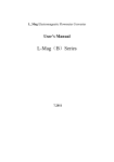
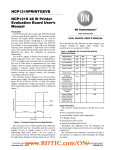
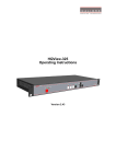
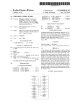
Electromagnetic Flowmeter Converter User’s Manual Shanghai Cowell Machinery Co.,Ltd. CONTENTS 1. THE PRODUCT FUNCTION INTRODUCTION ........................................................... 1 1.1 BASIC FUNCTION ........................................................................................................... 1 1.2 ESPECIAL FUNCTION ...................................................................................................... 1 1.3 NORMAL OPERATING CONDITIONS ................................................................................... 2 1.4 TYPE OF CONNECTING WITH SENSORS .............................................................................. 2 1.5 PLOT OF INSTALLING MEASURE ....................................................................................... 2 2. BASIC CIRCUIT OF CONVERTER ............................................................................... 4 3. INDEX OF TECHNICAL PERFORMANCE .................................................................. 5 3.1 STANDARD OF IMPLEMENT .............................................................................................. 5 3.2 BASIC PARAMETERS AND PERFORMANCE INDEX .............................................................. 5 4. OPERATION CONVERTER ........................................................................................... 8 4.1 KEYS AND DISPLAY ........................................................................................................ 8 4.2 SECTION PICTURE OF CONVERSION ................................................................................. 9 4.3 CONNECTIONS OF SENSOR ............................................................................................ 10 4.4 CHARACTERISTIC AND CONNECTION OF CABLE ............................................................. 13 4.5 DIGITAL OUTPUT AND CALCULATE ................................................................................. 16 4.6 SIMULATION SIGNAL OUTPUT AND CALCULATE .............................................................. 19 5. SETTING PARAMETERS ............................................................................................. 22 5.1 KEYS FUNCTION ........................................................................................................... 22 5.2 FUNCTION KEYS FOR SETTING PARAMETERS .................................................................. 23 6. RECORDING TIME WHEN POWER TURN-OFF (WITH POWER TURN-OFF FUNCTION) ....................................................................................................................... 33 6.1 DISPLAYING TURN-OFF POWER TIME .............................................................................. 33 6.2 ERASING “TURN-OFF POWER” RECORDING ..................................................................... 34 6.3 EXAMINE POWER-OFF RECORDS .................................................................................... 34 6.4 CLEAR THE RECORDS.................................................................................................... 34 7. RECORDING GROSS OF HOUR( HAS HOUR GROSS RECORDING FUNCTION) ............................................................................................................................................. 35 7.1 FUNCTION PARTS .......................................................................................................... 35 7.2 FORMAT ....................................................................................................................... 35 7.3 CHECK THE GROSS ....................................................................................................... 35 7.4 CLEAR THE RECORDS.................................................................................................... 35 8. INFRARED TELECONTROL FUNCTION KEYS ...................................................... 36 9. ALARM INFORMATION.............................................................................................. 36 10. TROUBLESHOOTING ................................................................................................ 37 10.1 NO DISPLAY: .............................................................................................................. 37 10.2 EXCITING ALARM ....................................................................................................... 37 10.3 EMPTY PIPE ALARM .................................................................................................... 37 10.4 MEASURE FLOW DISALLOW ........................................................................................ 38 11. L_MAG ENCASEMENT AND RESERVE .................................................................. 38 11.1 L_MAG ENCASEMENT ................................................................................................. 38 11.2 SHIPPING AND STORAGE .............................................................................................. 38 APPENDIX ONE: SELECTION OF EXCITING FREQUENCY (RE.) ........................... 39 Appendix Two ON/OFF Switch Diagram ....................................................................... 41 Appendix Three:HART function explaination ................................................................. 42 Electromagnetic Flowmeter Converter Instruction Manual 1. The product function introduction 1.1 Basic function ■ Low-frequency square-wave exciting,exciting frequency:1/10 power frequency、1/16 power frequency、1/25 power frequency、1/32 power frequency; ■ High-frequency square-wave exciting,exciting frequency:1/2 power frequency(for grouting liquid measure); ■ Exciting current can be selected for 125mA、187.5mA、250mA; ■ No need to add empty pipeline measurement, and can measure continuously, alarm by fixed value; ■ Current speed range:0.1 --- 15m/s,current speed resolution:0.5mm/s; ■ AC high-frequency switching power,range of voltage:85VAC --- 250VAC; ■ DC 24V switching power,range of voltage:16VDC --- 36VDC; ■ Network function : MODBUS ( RS-232C 、 RS-485 )、 HART and PROFIBUS –DP(choose); ■ Chinese or English displaying mode, (other languages can be set); ■ Three integrator gross inside, respective register:Forward gross, reverse gross and minus value gross. 1.2 Especial function ■ Recording time when power turn-off, to record power broken time of instrument system automatically and recruit to count the missing flux; ■ Recording function of hour gross, to record the flux gross by hour, fit for timed measure; ■ Infrared handing telecontrol keyboard,all the functions of far-untouched controlling 1 converter. 1.3 Normal operating conditions Ambient Temperature Ranges:fission –10~+ 60℃; Relative Humidity:5%~90%; Power Supply: 85~250V,45~63Hz ( single-phase AC). Dissipation Power: <20W( After connecting sensor). 1.4 Type of connecting with sensors The integrated circinal shells: circinal shells, shells connect with the flange directly, explosion-proof; The integrated squared shells: squared shells, shells connect with the flange directly; The split squared shells: squared shells (hang on the wall), Signal converters connect with cable of sensor; 1.5 Plot of installing measure Fig.1 Exterior size of the integrated circinal shells 2 Fig.2 Exterior size of the integrated squared shells Fig.3 Exterior size of the split squared shells 3 2. Basic circuit of converter 3 2b i t CPU A/D RO M exciting circuit EEROM preampli fier 85~260V 45~63Hz 4-20mA or 0-10mA 1-5000Hz Frequency or Pulse Output Switching Power Supply Current Output Keyboard Pulse Output Status Control OC Gate Status Output RS485 LCD Display Communication Interface Fig.2. 1 Structure of Converter’s Circuit The converter can supply exciting current to the coil in the sensor of electronetic flowmeters,the head amplifier amplifies the electromotive force from the sensor and converts it into standard signals of current or frequency so that the signals can be used for displaying, controlling and processing. See structure of converter circuit shown in Fig.2.1。 4 3. Index of technical performance 3.1 Standard of implement The design, production and instrument of Electromagnetic Flowmeter Converter implement 《JB/T 9248-1999 Electromagnetic Flowmeters》 。 3.2 Basic parameters and performance index 3.2.1 Pipe’s inside diameter of relative sensor (mm): 3、6、10、15、20、25、32、40、50、65、80、100、125、150、200、250、300、 350、400、450、500、600、700、800、900、1000、1200、1400、1600、1800、2000、 2200、2400、2600、2800、3000; 3.2.2 Request of relative sensor Sensitivity of sensor signal: under 1m/s, output 150µV ~200µV; For L_Mag electromagnetic flowmeter signal converters, there are four currents of 62.5 mA in exciting loop, which make up of 250mA, and every 62.5mA is controlled by one 20Ω exact resistance. So user can choose different exciting current by changing the number of exact resistance. The current will be 250mA when the signal converters leave factory, as such, if there are three exact resistance, the current will be 187.5 mA; if two, 125mA; Resistance of sensor exciting coil: 250mA exciting current:50 ~ 60Ω; 187mA exciting current:60 ~ 80Ω; 125mA exciting current:100 ~ 120Ω; 5 3.2.3 Measure precision for assembly Table 3.1 VS:Setting measurement range (m/s) Diameter(mm) Range(m/s) Accuracy ≤0.3 ±0.25%FS 0.3~1 ±1.0R 1~15 ±0.5%R 0.1~0.3 ±0.25%FS 0.3~1 ±0.5%R 1~15 ±0.3%R 0.3 以下 ±0.25%FS 0.3~1 ±1.0%R 1~15 ±0.5%R 3 ~ 20 25 ~600 700~3000 %FS:for relative ranges; %R:for relativevalue of measurement 3.2.4 Simulated current output Load resistor: 0~1.5kΩ (0~10mA); 0~750Ω (4~20mA). Basic Errors: 0.1%±10μA. 3.2.5 Digital frequency output Frequency output range: 1~5000Hz; Output electric isolate: Photoelectric isolate. Isolate voltage: > 1000VDC; Frequency output drive: output by field-effect transistors, the highest subjected voltage is 36VDC,maximum of output current is 250mA. 3.2.6 Digital pulse output Pulse output value: 0.001~1.000 m3 / cp、 6 0.001~1.000 Ltr / cp、 Pulse output width: 20ms. Pulse output isolate: photoelectricity isolate. Isolate voltage: > 1000VDC; Pulse output drive: output by field-effect transistors, the highest subjected voltage is 36VDC,maximum of output current is 250 mA. 3.2.7 Alarm output Alarm output junction:ALMH--- upper limit; ALML--- lower limit; Output isolate: photoelectricity isolate. Isolate voltage: > 1000VDC; Alarm output drive: output by Darlington pipe, the highest subjected voltage is 36VDC,maximum of output current is 250mA. 3.2.8 Digital communication port and protocol RS-232C interface: designed by standard of IEEE RS-232C, un-electric isolate; RS--485 interface: designed by standard of IEEE RS---485, electric isolate; MODBUS interface: format of RTU,electric isolate 1000V; HART interface: designed by standard of HART , if you choose our hand held unit , you can display the measure value on line,and setting the parameters. PROFIBUS interface: designed by standard of PROFIBUS – DP. 3.2.9 Electric isolate Insulated voltage between simulated input and simulated output should be higher than 500V; Insulated voltage between simulated input and alarm power supply should be higher than 500V; Insulated voltage between simulated input and AC power supply should be higher than 500V; Insulated voltage between simulated output and AC power supply should be higher than 500V; 7 Insulated voltage between simulated output and earth should be higher than 500V; Insulated voltage between pulse output and AC power supply should be higher than 500V; Insulated voltage between pulse output and earth should be higher than 500V; Insulated voltage between alarm output and AC power supply should be higher than 500V; Insulated voltage between alarm output and earth should be higher than 500V; 4. Operation converter 4.1 Keys and display 4.1.1 Squared define keys and LCD screen display Alarm Indicator Flow Volume Flow Velocity Percentage Conductivity Ratio ! Flow Volume+2578.5m3/h ∑+023456789m 3 Forward & Reverse Integrated Volumes Deference of Forward and Reverse Integrated Volumes Display Alarm Content Enter: With ALT Key to form Enter and OK UP: Plus 1,Page UP, With OK Key to form Right Move Down: Minusl, Page Down, With OK to form Left Move Compound Key Fig. 4.1(a) Keys on squared panel and LCD display: -066.08 Alarm Type SYS 15:47 Flow volume Unit Time m3/Hr +0000000415 Flow velocity Ratio of Emptiness Percentage Y/M/D/Hour/Min/Second Forward & Reverse Integrated Volumes Deference of Forward and Reverse Integrated Volumes Enter : With ALT Key to form Enter and OK UP: Plus 1,Page UP, With Shift to form Right Move Down: Minusl, Page Down, With Shift to form left Move Compound Key Fig. 4.1 (b) Keys on squared panel and large LCD display: 4.1.2 Rotundity define keys and LCD screen display 8 -76.570 Alarm Indicator Lo ×1m3/Hr Flow volume limit 000000013.5m3 Unit Flow Velocity Ratio of Emptiness Percentage Forward & Reverse Integrated Volumes Deference of Forward and Reverse Integrated Volumes Enter UP:Plus 1,Page UP Down:Minus1,Page Down Compound Key Fig. 4.1 (c) Keys on circinal panel and big LCD display Note: When measuring, pushing down “Compound Key + Enter” will appear password of changing state, base on distinction of secrecy, and change the password as we provide. Then pushing “Compound Key + Enter” again, and you can inter the state of setting parameter. If want to return to the running state, push “Enter” for several seconds. 4.2 Section picture of conversion 4.2.1 Section picture of the split squared shells with small LCD and no communication Fig.4.2 (a) Section picture of the split squared shells with small LCD and no communication Note: (1) Front Cover, (2) LCD, (3) Cable, (4) Back Cover, (5) Place for Communication Board; (6) Cable for Display (Flat face to LCD/20 Lines); (7) Connectors; (8) Lock for Cover. 4.2.2 Section picture of the split squared shells with big LCD and communication 9 Fig.4.2 (b) Section picture of the split squared shells with large LCD and communication Note: (1) Front Cover; (2) Key Cable; (3)Large LCD; (4)Keyboard Cable (Flat Face to LCD/16 Lines);(5) Back Cover; (6) Communication Board; (7) Cable for LCD (Flat face to LCD/20 Lines; (8) Communication Cable (Flat Face to Communication Board/16 Lines); (9) Two Wired Communication Lines; (10) Connectors; (11) Lack for Cover. 4.3 Connections of sensor 4.3.1 Connectors and labels for the squared SIG1 SGND SIG2 DS1 SGND DS2 ICCOM TRX+ VDCIO TRXICOUT INSW EXT+ EXT- ALM+ POWER ALMALCOM L2 L1 PE PUL+ PULPDIR PCOM RS485 PE Fig.4.3 (a) Connectors for the squared 10 Labels of connectors in squared model SIG1 SGND SIG2 DS1 DS2 INSW EXT+ EXT- Signal1 Signal Ground Signal2 Shielded Exciting1 Shielded Exciting2 12V Pull Power Exciting Current+ Exciting Current- To Separate Model Sensor VDCIO ICOUT ICCOM 24V Pull Power Analog Current Output Analog Current Output Ground Analog Current Output PUL+ PULPDIR PCOM Flow Direction ALM+ ALMALCOM Upper Limit Alarm Output Low Limit Alarm Output Alarm Output Ground Flow Frequency (Pulse) Output Frequency (Pulse) Output Frequency (Pulse) Output Ground Two Alarm Outputs 4.3.2 Signal lines and labels in squared model ф 2 T erm inal C old-W elded ф 2 T erm inal C old-W elded M etal Screen ф 10 H eat Shrink T ube M etalScreen ф 10 H eatShrink T ube R ed 32 C onductor Shielded C able R ed 32 C onductor Shielded C able G reen 32 C onductor Shielded C able G reen 32 C onductor Shielded C able C able for Flow Signals:R V V P2ⅹ32 /0.2 Fig.4.3 (b) Connection and labels of signal lines in squad model 4.3.3 Links and labels of connectors in Circinal Model + COM I+ COM P+ AH AL + + + + + + T+ G + + + + + + + FUSE + L2 L1 + + T- Fig.4.3(c) Connectors in circinal model 11 Symbols and Description of Connectors in Circinal Pane I+: Output Current for Flow Measurement COM: Output Current (Ground) for Flow Measurement P+: Frequency(Pulse) Output for Bi-directional Flow COM: Frequency (Pulse) Output (Ground) AL: Alarm Output for Low Limit AH: Alarm Output for Upper Limit COM: Alarm Output (Ground) FUSE: Fuse for Power Supply T1+: +Communication Input Signal T2-: -Communication Input Signal G: RS232 Communication Ground L1: 220V(24V)Power Supply L2: 220V(24V)Power Supply 4.3.4 Labels and connection of signal lines in circinal model W hite C able R ed 12 C onductor Shielded C able) B lack 12 C onductor Shielded C able R ed 10 C onductor Shielded C able B lue 13 C onductor Shielded C able Shield Screen B lack Shielded C able Fig.4.3 (d) Labels and connection of signal lines in circinal model Signal lines labels in circinal model: White twisted-pair cable (for exciting current): 12 Conductors (Red) 12 Conductors (Black) Black shielded twisted-pair cable:10 Conductors (Red) connected to “Signals 1” 13 Conductors (Blue) connected to “Signals 2” Shielded Conductor connected to “Signal Ground” 12 4.4 Characteristic and connection of cable 4.4.1 Flux signal line When separated models of converters are assembled with sensors for measuring flow of fluid which conductivity is larger than 50μS/cm, PVVP 2*0.2 mm2 model cable ( metal shielded signal cable covered with PVC) can be used as communication cable for flow signals. The length of signal cable should be less than 100 m. Signal cables have to be connected to sensors that were assembled by producers. Connections of signal cables are shown in Fig.4.3 (b) for squire-shaped models and Fig.4.3 (d) for circle-shaped models, respectively. The converter can output equivalent level of shielded exciting signal voltage so that interference to flow measurement signals can reduced by means of lowering the distributed capacitance of communication cable. When measured conductivity is less than 50μS/cm or signals are transferred in remote distances, double-conductor and double-shielded signal cable at equivalent level of voltage can be used. For example, special STT3200 cable or BTS model signal cable (triple-shielded) can be used for signal communication. 4.4.2 Exciting current cable Two conductor and insulating rubber- covered cables can be used as exciting current cables. Suggested model is RVVP2*0.3mm2. Length of exciting current cable should be equal to that of signal cable. When the model STT3200 cables are used for exciting current and signals, two cables can be put together as one cable. 4.4.3 Output and power line All cables for signals transferring and power supply has to be prepared by users. However, it should be careful to choose the cables that meet the upper limit load of consuming current. Note: When DIP switch next to terminal is set to ON places, the converter from its inside 13 can provide +28Vpower supply and up-pull 10kΩresistance to output Frequencies (PUL+,PUL-) to isolated OC gate, Alarm Output (ALM+.ALM-), and Status Control (INSW).Therefore, when converter has frequency output and works with sensor together, DIP switch can be set as ON getting frequency signals from PUL+ and PCOM terminals. Pulse current output, alarm current output and external power supply can see in Fig.4.4 (a). When inductive load is connected to converter, diode should be used as in Fig.4.4 (b). The Meter Current + ICOUT ICCOM Fig.4.4 (a) Output current circuit ON Integrated Current + 123456 PCOM DC Power Supply - PUL+ VDCIO - Fig.4.4 (b) Connection of electro-magnet counter 14 ON Integrated Flow PCOM PUL+ 123456 Fig.4.4 (c) Connection of electronic counter ON L ow L im itA larm ALCOM ALM+ ALM- D C Pow er Supply - + U pper L im it A larm Fig.4.4 (d) Connection of alarm output inside outside PUL+ PDIR ALM PCOM ALCOM Fig.4.4 (e) Connection of OC gate 15 4.4.4 Grounding Contact area of copper Connector PE on Converter Cabinet for grounding should be larger than 1.6mm2.Contact resistance should be less than 10Ω. 4.5 Digital output and calculate Digital output means frequency output and pulse output, and both of them use the same output point, so user can choice only one type of them but not both. 4.5.1 Frequency output Frequency output range is 0~5000HZ, and corresponding the percent of flux. F= Measure value frequency range Full scale value The up limit of frequency output can be adjusted. It can be choice from 0 ~ 5000HZ, and also can be choice low frequency: such as 0 ~ 1000HZ or 0 ~ 5000HZ. Frequency output mode general can be used in control application, because it responses the percent flux. Users can choice pulse output when the equipment is applied to count. 4.5.2 Pulse output mode: Pulse output mainly applies in count mode. A pulse output delegates a unit flux, such as 1L or 1M3 etc. Pulse output unit divide into 0.001L, 0.01L, 0.1L, 1L, 0.001M3, 0.01M3, 0.1M3, 1 M3, 0.001UKG, 0.01UKG, 0.1UKG, 1UKG, 0.001USG, 0.01USG, 0.1USG, 1USG. When choice the pulse unit, they should notice the match of the flux range of flowmeter and pulse unit. For volume flux, count formula as follows: QL=0.0007854×D2×V (L/S) Or QM=0.0007854×D2×V×10-3 (M3/S) Note: D-nozzle (mm) V-velocity of flow (m/s) The oversize flux and too small pulse unit will be made the pulse output over the up limit. Generally, pulse output should be controlled below 2000P/S. However, the too small flux 16 and too large pulse unit will be made the instrument exports a pulse long time. Otherwise, pulse output is different from frequency output. When pulse output cumulates a pulse unit, it exports a pulse. Therefore, pulse output is not equality. Generally, measure pulse output should choice count instrument, but not frequent instrument. 4.5.3 The connection of digital output Digital output has three connected points: digital output connected point, digital ground point, and symbol as follows: PUL+----- digital output point; PCOM ----- digital ground point; PDIR ------- flux direction junctions. Commonly liquid flows for one direction and at this time user can just use digital output point and digital ground point. But if user wants to know the direction, can use the PDIR. PUL+ and PDIR use PCOM together, PUL+ and PDIR are both collector plough output, user can connection as the below circuit. 4.5.4 The connection of digital voltage output PUL Pin R E Inside Pcom + - User equipment Voltage input Com Fig.4.5 (a) the connection of digital voltage output 4.5.5 Digital output connect photoelectricity coupling (PLC etc.) 17 PUL R + - E inside User equipment Pcom Fig.4.5 (b) Digital output connect photoelectricity coupling Commonly user’s photoelectricity coupling current is about 10mA, so about E/R=10mA, E=5~24V. 4.5.6 Digital output connect relay J PUL E inside + - D Pcom Fig.4.5(c) Digital output connect relay Commonly relay needs E as 12V or 24V. D is extend diode, now most middle relays has this diode inside. If not have, user can connect one outside. Table of digital output parameter: 18 POUT and PDIR Parameter Test condition Mini Typical Max Unit Volatge IC=100 mA 3 24 36 V Current Vol≤1.4V 0 300 350 mA 0 5000 7500 HZ Frequency IC=100mA Vcc=24V High voltage IC=100mA Vcc Vcc Vcc V Low voltage IC=100mA 0.9 1.0 1.4 V 4.6 Simulation signal output and calculate 4.6.1 Simulation signal output There are two signal system: 0~10mA and 4~20mA, user can select from parameter setting. Simulation signal output inner is 24V under0~20mA, it can drive 750Ω resistance. The percent flux of simulation signal output: I0= Measure value the scale of current + the zero point of current Full scale value The current zero is 0 when 0~10mA, and the current zero is 4mA when 4~20mA. It can be advanced simulation signal output distinguish. User can select the range of measure. The manufacture’s parameter have been adjusted, it can’t need adjust. If have abnormity, it can consult 4.6.2. 4.6.2 Simulation Signal Output Adjust (1)The Converter adjust preparative When the converter is running 15 minutes, the inner of converter becomes stabilization. 19 Preparative 0.1% amperemeter or 250Ω、 0.1% voltage instrument. 1.000 IOUT DC20V Converter ICOM (2)Current zero correct When the converter getting into parameter setting, selecting to “Analog Zero” and enter to it. The standard of signal fountain getting to “0”.Adjust parameter make amperemeter is 4mA(±0.004mA). (3)The full scale current correct To select “Anlg Range” to enter.Adjust the converter parameter make amperemeter is 20mA(±0.004mA) Adjust the current zero and the full range, the current function of the converter reached exactness.The line degree of current output of conversion should be controlled within the scope of 0.1%. (4) Current line degree checking You can place the standard signal source in 75%、50%、25%,and check the line degree of current output 20 4.6.3 L_mag electromagnetic flowmeter converter’s connection of current output: User system IOUT ~ ~ L_Mag converter DC24V ~ ~ IVIN + Signal input - R COM Fig.4.6 (a) L_Mag two connection Power (+24V) ~ ~ User system L_Mag 24V -Signal input Power - COM ~ ~ converter ~ ~ IOUT + COMM Fig.4.6 (b) L_Mag three connection( power supply and current output are not insulated) User system ~ ~ Power +24V 24V ~ ~ Power - L_Mag ~ ~ IOUT COMM ~ ~ converter + - Signal input COM Fig.4.6 (c) L_Mag four connection( power supply and current output are insulated) 21 5. Setting parameters After L_mag electromagnetic flowmeter converter and sensor connect to the pipe (no matter demarcate or use), may do the next work first: Connect the pipe fore-and-aft the sensors tighten. Make sure the sensor connects the earth. Make sure the liquid stillness when regulating zero of the instrument. Make sure the oxidation velum of sensor makes steadily (electrode and liquid contact continuously about 48 hours). Two running ways: Self-testing way Parameter setting way When electrify, the instrument comes into measure way automatically, and under this way it can do all the functions and display data. Under the parameter setting way, user can set the parameter by the four keys. 5.1 Keys function 5.1.1 “Down” key function in self- testing way “Down” key: Selecting displayed data on lower line in turn; “Up” key: Selecting displayed data on higher line in turn; “Compound” key + “Enter” key: Come into parameter setting “Enter” key: Press it to come into the picture of select function. Under the measure, adjust of the LCD contract: the squared with small LCD uses “Compound” key + “Up” key or “Compound” key + “Down” key for several seconds; other LCDs use the potentiometer behind the LCD. 5.1.2 Function keys for parameters setting “Down” key: Subtract 1 from the number at cursor area; “Up” key: Add 1 to the number at cursor area; 22 “Compound” key + “Down” key: Cursor turns left; “Compound” key + “Up” key: Cursor turns right; “Enter” key: In/Out submenu; “Enter” key: Press for two seconds under any state and will return to automate measure way. Note: (1) When use “Compound” key, you should press “Compound” key and “Up” or “Down” both; (2) It will return to the measure way automatically after 3 minutes when under the parameter setting way; (3) Direct select of zero correction about the flow, you can move the cursor to the left + or - , and use “Down” or “Up” to switch; (4) Unit select of flow, you can move the cursor to “Flow Range”, and use “Down” or “Up” to switch. 5.2 Function keys for setting parameters To set or correct working parameters, the converter should be running in parameters setting way instead of measuring status. In measuring status, click “Enter” keys getting to the select of parameter and transfer password (0000), and then correct the password with one of the new passwords that are provided by manufacturer. Finally, push the “Enter” keys to work in Parameters Setting Way. There are 6 Passwords in design and among them 4 for deferent operators in secret and 2 are fixed passwords for system operation. 5.2.1. Parameters setting menu There 52 parameters of L-Mag, user can set every parameter. The List of Parameters is 23 shown below: Setting Parameters in Menu Code Parameter words Setting Way Grades Range 1 Language Select 2 Chinese/English 2 Com Addres Set count 2 0~99 3 Baud Rate Select 2 600~14400 4 Com Protocol Select 2 Type 1、Type 2 5 Sensor Size Select 2 3~3000 6 Flow Range Set count 2 0~99999 7 Flow Rspns Select 2 0~100 8 Flow Direct Select 2 Forward/ Reverse 9 Flow Zero Set count 2 ±0.000~±9.999 10 Flow Cutoff Set count 2 0~99% 11 Cut Disp Ena Select 2 Enable/Disable 12 Total Unit Select 2 0.001L~m3 13 Segma_N Ena Select 2 Enable/Disable 14 Analog Type Select 2 0~10mA /4~20mA 15 Pulse Type Select 2 Freque / Pulse 16 Pulse Unit Select 2 0.001L~1m3 17 Frequen Max Select 2 1~ 5000 HZ 18 Mtsensor Ena Select 2 Enable/Disable 19 Mtsnsr Trip Set count 2 999.9 % 20 Mtsensor Crc Set count 2 0.0000~3.9999 21 Alm High Ena Select 2 Enable/Disable 22 Alm High Val Set count 2 000.0~ 199.9 % 23 Alm Low Ena Select 2 Enable/Disable 24 Alm Low Val Set count 2 000.0~199.9 % 25 Clear Total Password 3 000000~399999 24 26 Total Key Set count 4 000000~399999 27 Sensor Code1 User set 5 Finished Y M 28 Sensor Code2 User set 5 Product number 29 Sensor Fact Set count 5 0.0000~3.9999 30 Field Type Select 5 Mode 1,2,3,4 31 Flow Factor Set count 5 0.0000~3.9999 32 Mult Factor Set count 5 0.0000~3.9999 33 Analog Zero Set count 5 0.0000~1.9999 34 Analog Range Set count 5 0.0000~3.9999 35 Meter Factor Set count 5 0.0000~3.9999 36 MeterCode 1 Factory set 5 Finished Y M 37 MeterCode 2 Factory set 5 Product Serial No 38 FwdTotal Lo Correctable 5 00000~99999 39 FwdTotal Hi Correctable 5 00000~39999 40 RevTotal Lo Correctable 5 00000~99999 41 RevTotal Hi Correctable 5 00000~39999 42 Year User correct 5 00~99 43 Month User correct 5 00~99 44 Day User correct 5 00~99 45 Hour User correct 5 00~99 46 Minute User correct 5 00~99 47 Second User correct 5 00~99 48 Pass Word 1 User correct 5 0000~9999 49 Pass Word 2 User correct 5 0000~9999 50 Pass Word 3 User correct 5 0000~9999 51 Pass Word 4 User correct 5 0000~9999 52 Load Preset Factory set 6 Initialize password Note: 4 and 13 don’t use when drop time, 43~49 are recording time when power turn-off, no this function no these parameters. 25 5.2.2 Converters parameters Parameters of converters can decide the running status, process and output ways as well as state of output. Correct option and setting of parameters can keep the converters running optimally and get higher accuracies of output bother in display and in measurement. There are 6 grades of passwords for setting parameters function. Grades 1 to grade 5 of passwords are for users and grade 6 of password is for manufacturer. Users can reset their passwords of grades 1~4 in grade 5. Users can check converters parameters in any grade of password. However, if users want to change parameters pf converters, deferent grade of parameters have to be used by the users. Grade 1 of password (set by manufacturer as 0521): users can only read parameter. Grade 2 of password (set by manufacturer as 3210): users can change 1~24 parameters. Grade 3 of password (set by manufacturer as 6108): users can change 1~25parameters. Grade 4 of password (set by manufacturer as 7206): users can change 1~26parameters. Grade 5 of password (Fixed): users can change 1~51 parameters. Password Grade 5 can be set by skilled users. Grade 4 is mainly used for resetting total volume in password. Grades 1~3 can be set by any one who can be chosen by users. 5.2.2.1 Language There are 2 languages for L-Mag converter operation. They can be set by users according to the users needs. 5.2.2.2 Com Addres It means this instrument’s address when communicates with many, and has 01~99 , holding the 0. 5.2.2.3 Baud Rate 600, 1200, 2400, 4800, 9600 and 14400 baud rate. 5.2.2.4 Com Protocol Tpye 1 is 485 communicates, Type 2 is other special communicates. 26 5.2.2.5 Sensor Size Converters can be equipped with some deferent sensors that have deferent diameter of measuring pipes. The pipes in deferent diameters from 3mm to 3000mm can be chosen in relative table. 5.2.2.6 Flow range Flow range means upper limit value, and lower limit value is set “0” automatically. So, it makes the range, and makes the relation of percent display, frequency output and current output with flow: Percent display = (flow measure / measure range) * 100 %; Frequency output = (flow measure / measure range) * frequency full; Current output = (flow measure / measure range) * current full + base point; Pulse output will not affect. Notice:The flow unit can choose form the parameters (L/s、L/min、L/h、m3/s、m3/min、 m3/h),and the user can choose the proper unit according to the technological requirement and using habit. Notice: Using 5 valid to show the value of the flow, with the volume unit following the last valid. The microprocessor can remind the users of the set mistakes leading to the upper limit and lower limit overflow causing by unsuitable choosing the volume unit. For example, when caliber is 200mm and choose l/h as the display volume unit, if the speed of the volume is 1m/s and the volume is 113097 L/h, the figures is more than 5 valid and cause upper limit overflow, and “error” is showed on the panel. So now the volume unit can be chose from m3/s、m3/min and m3/h.While caliber is 3mm,choose m3/s as the volume unit and the volume is 0.00000707m3/s,it is impossible to show the valid using 5 valid and causing lower limit overflow, and “error” is showed on the panel. So now the volume unit can be chose from L/s、L/min or L/h. 5.2.2.7 Flow Rspns 27 It means time of filter measure value. The long one can enhance the stability of flow display and output digital, and fits for gross add up of pulse flow; the short one means fast respond rate, and fits for production control. It is set by select. 5.2.2.8 Flow Direct If users think the direct and design are differ, just change the direct parameter is OK, but not change exciting or signal. 5.2.2.9 Flow zero Make sure the sensor is full of flow, and the flow is stillness. Flow zero is shown as velocity of flow, mm/s. FS = ○ ○ ○ ○ ○ ± ○ ○ ○ ○ ○ Converter’s zero-flow correction displays like this: Upper small words: FS means measure value of zero; Lower large words: correction value of zero. When FS is not “0”, make FS = 0. Note: if change the value on next line and FS increases, please change the “+, -” to correct FS to zero. Flow zero is the compound value of the sensor, and should be recorded in sensor list and band. The unit will be mm/s, and the sign will be opposite with correction value. 5.2.2.10 Flow Cutoff Flow cutoff is set in percentage of Upper Limit Range of flow, and users can delete all Negligible Small Signals of flow volume, velocity and percentage out of displaying and outputting them. Sometimes user can delete output of current output signal and frequency (pulse) output signal only to have flow, velocity and percentage being displayed. 5.2.2.11 Total Unit Converter display is counter with 9 bits, and the max is 999999999. 28 Integrator units are L, m3, UKG and USG (liter, stere, English gallon, American gallon). Flow integrator value: 0.001L、 0.010L、 0.100L、 1.000L 0.001m3、 0.010m3、 0.100m3、 1.000m3 ; 5.2.2.12 Segma_N Ena When “SegmaN Ena” is “enable”, if the flow flows, the sensor will export pulse and current。 When it is “disable”, the sensor will export pulse as “0” and current as “0”(4mA or 0mA) for the flow flows reversals. 5.2.2.13 Analog Type Output current types can be chosen by users as 1~10mA or 4~20mA practically. 5.2.2.14 Pulse Type Two kinds of Pulse Outputs are can be chosen: Frequency Output and Pulse Output. Frequency Output is continuous square waveform and Pulse output is a serial wave of square wave. Frequency output is mainly used for instant flow and total integrated flow in short time measurement. Frequency output can be chosen in equivalent frequency unit and volume of integrated flow can be displayed. Frequency Output can be used in long time measurement for total integrated flow with volume units. Frequency output and pulse output are usually from OC gates so that DC power supplies and load resistors have to be required (See Part 4.5). 5.2.2.15 Pulse Unit Equivalent pulse Unit is referred to one pulse for value of flow. The range of pulse equivalent can be chosen: Pulse Equivalent Flow 1 0.001L/cp 2 0.01L/cp 3 0.1L/cp 29 4 1.0L/cp 5 0.001m3/cp 6 0.01m3/cp 7 0.1m3/cp 8 1.0m3/cp Under the same flow, the smaller pulse, the higher frequency output, and the smaller error will be. The highest pulse output is 100cp/s, and mechanism electromagnetic counter can get 25 frequency/s. 5.2.2.16 Frequen Max Frequency output range is as the upper limit of flow measure, just the percent flow 100%. Frequency output upper limit can be selected between 1~5000Hz. 5.2.2.17 Mtsensor Ena The state of empty pipe can be detected with the function of converter. In the case of Empty Pipe Alarm, if the pipe was empty, the signals of analog output and digital output would be zero and displayed flow would be zero, too. 5.2.2.18 Mtsnsr Trip The sensor use flow resist rate to judge whether full of pipe, so empty pipe value is a continuum value. Even though different flow has different resist rate, when the flow is full, the resist rate is steady. It uses relative resist rate to calculate empty measure value, define the full pipe resist rate 100%, as empty pipe alarm to adjust to 100%, when flow surface is lower than the electrode, the electrode touches the air and the rate will be higher, so the instrument displays empty pipe alarm. For fact use, when the flow is full of pipe after adjusting empty pipe to 100% and the surface is lower than the electrode completely, L_Mag empty pipe value will get 1000% all more. So empty pipe alarm set at about 900% and can alarm empty state correctly. When the surface drops from full to empty, it will hang some liquid on the wall, and this 30 will lead the empty pipe measure not to get the max immediately but needs some time. So if want empty alarm reacts quickly, make the threshold smaller as 500%. 5.2.2.19 Mtsensor Crc Liquid specific conductance is different because of different mediator and area. The instrument can’t determine threshold of empty pipe alarm in every condition detailedly. So ,L_Mag uses mathematics normalization method to set threshold as the method of setting alarm percentage by users . Instrument designing has an amendment coefficient of empty pipe.No matter which mediator ,where the instrument being used, if in the condition of full packages, we adjust empty pipe amendment coefficient to make instrument indicating relative conductance be 100% ,then set empty pipe alarm threshold between 500% and 999% to finish operation of empty pipe alarm. 5.2.2.20 Alm High Ena Users can choose “Enable” or “Disable”. 5.2.2.21 Alm High val The parameter of upper limit alarm is percentage of flow range and can be set in the way of setting one numerical value between 0%~199.9%.When the value of flow percentage is larger than the value of setting value, the converter outputs the alarm signal. 5.2.2.22 Alm low The same as upper limit alarm. 5.2.2.23 Sensor Code It is referred to the produced date of sensor and the serial number of product that can keep the sensors coefficient right and accurate. 5.2.2.24 Sensor Fact “Sensor Coefficient” is printed on the Label of the sensor when it is made in factory. The 31 “sensor coefficient” has to be set into Sensor Coefficient Parameter when it runs with converter. 5.2.2.25 Field Type The Meter afford three exciting frequency types: 1/10 frequency (type 1), 1/16 frequency (type 2), 1/25 frequency (type 3) and 1/32 frequency (type 4). The small-bore one should use 1/10 frequency, and large-bore one should use 1/16 or 1/25 frequency. When using, please select type 1 first, if the zero of velocity is too high, select the type 2 or type 3. Note: Demarcate on which exciting type, working on it only. 5.2.2.26 Flow Factor Flow Verification Coefficient is the Converter Verification Coefficient. Users must calibrate the converters by means of general standard verifiers. Setting this coefficient to make that all converters have the same features in work, the converters can match the sensors for flow measurement. 5.2.2.27 Mult Factor This is used to bright dyke diving measure, such as one sensor is compounded with two alike caliber pipes, then the factor is 3.0000. 5.2.2.28 FwdTotal Lo and hi Positive total volume high byte and low byte can change forthcoming and reverse total value, and be used to maintenance and instead. User use 5 byte code to enter, and can modify the positive accumulating volume (∑+). Usually, it is unsuitable to exceed the maximum the counter set(999999999). 5.2.2.28 RevTotal Lo and hi User use 5 byte code to enter, and can modify the negative accumulating volume (∑-). Usually, it is unsuitable to exceed the minimum the counter set(999999999). 5.2.2.29 Date (Year, Month, Day) and Time (Hour, Minute and Second) Users can set the date (Year, month, and day) and Time (hour, minute and second in 32 Password 5. 5.2.2.30 User’s password 1~4 Users can use 5 grades of passwords to correct these passwords. 5. 2.2.31 Analog Zero When the converters are made in the factory, output current have been calibrated to zero scale, that is, accurate 0mA or 4mA output. 5.2.2.32 Analog Range When the converters is made in the factory, output current have been calibrated to full scale, that is, accurate 10mA or 20mA output. 5.2.2.33 Meter Factor This fact is the special one of sensor-made-factory and the factory use this fact to unite L_Mag electromagnetic flowmeters converters to make sure all the instruments can interchange by 0.1%. 5.2.2.34 Converter code 1 and 2 Converter code records the date of manufacturing and serial number of converter. 6. Recording time when power turn-off (with power turn-off function) When power turns off, the liquid in the piping still flows that means the flower also exist. But because the power is cut, so the insctrument could not record. For resolving this problem, L_Mag electronics flowermeter designs length of power turn-off time function to record the power turn-off time and power turn-on time for user to deal with. 6.1 Displaying turn-off power time There is a clock for timing when power turns off (inside batteries power supply), which can work longer than 5 years. If using power turn-off time function, make sure this clock is OK. 33 a) Set year, month, day, hour, minute and second exactly. b) Make sure the power inside is enough(exchange batteries every 5 years). 6.2 Erasing “turn-off power” recording There are 256 record stores, and everyone records one power-off. When 256 numbers have stored, the time will not recorded anymore. Record format like this: 001 次 总019次 04月01日12时12分 本次 0000.20时 总计 0002.20时 Number Time This time Whole time Exactitude to minute. 6.3 Examine power-off records Push down key “Enter” to enter the model “Displaying Turn-off Time”: a) No power-off records, means there are no power-off records; push any key to return to “Flow Display Model”, b) If having power-off records, push “Up” key to display next recording and “Down” key to display preceding recording. Finally, Push down the key “Enter” to return to “Flow Display Model”. 6.4 Clear the records After user set down the records, it can clear all the records. Do like this: Step 1: push “Complex” + “Enter” to password setting; Step 2: input password: 4+11; Step 3: push “Complex” + “Enter” for a second to clear records. 34 7. Recording gross of hour( has hour gross recording function) At present, much flowmeter measure system uses ladder-time method, for example, some supply water system. For this complexion, L_MagB designs hour gross recording function. Use the unit as hour, record the gross flux in this hour, and supply gist to this method. 7.1 Function parts Hour gross recording function accords to the clock inside, so make sure the clock inside is OK. a) Set the year, month, day, hour, minute and second exactly; b) Make sure the power inside is enough (exchange batteries every 5 years). 7.2 Format There are 1024 record stores, and everyone records one hour power-off. When 1024 numbers have stored, the time will not recorded anymore. Record format like this: 0001 时记总量 06年04月01日15时 +Σ0000009862 -Σ0000000068 Time Date + Gross - Gross 7.3 Check the gross Push “Up” to the interface of hour gross, then push “Up” or “Down” to check, at last push “Enter” to return. 7.4 Clear the records The grosses of hours and cumulations are correlatively, so clear one, clear both. Do like this: 35 Push “Complex” + “Enter” to the password interface, input the 4 th password, then push “Up” to the Total Clear, and input the password to complete. The records will be cleared . 8. Infrared telecontrol function keys The operation of the infrared-hand-remote control keyboard is the same with the operation of the instrument. When use it, please keep the infrared transmitter of the infrared-hand-remote control keyboard and the receiver of the instrument parallel, with the distance of about one meter. Concrete operation referring to the figure: Mag Remote Key L≤ 1m Fig.8.1: The communication figure of the infrared-hand-remote control keyboard and the instrument 9. Alarm information PCB of electromagnetic flowmeters converters use SMT, so for user, it is unable to service, and cannot open the shell of converter. Intelligent converters have self-diagnose function. Without trouble of power and hardware circuit, the normal trouble can be alarmed correctly. This information displays “!” on the left of LCD. The trouble is like this: Hig Alm ---- Flow high limit alarm; Mtsnsr Alm ---- Flow empty pipe alarm; Low Alm ---- Flow low limit alarm; SYSTEM ALM---- System exciting alarm. UPPER ALARM ---- Flow high limit alarm; 36 LOWER ALARM ---- Flow empty pipe alarm; LIQUID ALARM ---- Flow empty pipe alarm; SYSTEM ALARM ---- System exciting alarm. 10. Troubleshooting 10.1 No display: a) Check the power supply connection; b) Check the power fuse to see for OK; c) Check the contrast of LCD and regulate it to working state; 10.2 Exciting alarm a) Check if the exciting cables EX1 and EX2 did not connected; b) Check if the total resistance of sensor’s exciting coil resistances less than 150Ω; c) If a) and b) are OK, the converter is failed. 10.3 Empty pipe alarm * If measured fluid full of testing pipe of sensor; * When shorting circuit three connectors SIG 1, SIG 2, SIGGND of converter, and no “Empty Alarm” displayed then the converter works OK. In this case, it is possible that conductivity of measured fluid may be small or empty threshold of empty pipe and range of empty pipe are set wrongly. * Check if the signal cable is OK; * Check if the electro-poles are OK or not. Let the flow is zero, then the displayed conductivity should be less than 100%. Resistances of SIG1 to SIGGND and SIG2 to SIGGND are all less than 50kΩ (conductivity of water) during measurement operation. (It is better to test the resistances by means of multimeter with pointer to see the charging process well.) 37 * The DC voltage should be less than 1V between DS1 and DS2 testing the voltage by means of multimeter. If DC voltage is larger than 1V, the electro poles of sensor were polluted that have to be cleaned. 10.4 Measure flow disallow * If measured fluid full of testing pipe of sensor; * Check if the signal cable is OK; * Check the sensor modulus and sensor zero whether set as the sensor scutche on or leave factory checkout. 11. L_Mag encasement and reserve 11.1 Encasement Electromagnetic flowmeter converter is packed as vacuum, and can insulate wet. The bag is appropriative one, if the bag is open, it will not product of original factory. Installation Manual, Certificate of Product and Packing List are all with the converter. 11.2 Shipping and storage To prevent the product from damage during shipping, keep the original package of manufacturer. The products should be stored in storehouse that meets following conditions: a) Keep off raining and moisture; b) Keep off heavy vibration, and strike; c) Ambient temperature -20~+60℃; d) Humidity less than 80%. 38 Appendix One: Selection of exciting frequency (re.) L_Mag afford three exciting frequency types: 1/10 frequency (type 1), 1/16 frequency (type 2), 1/25 frequency (type 3) and 1/32 frequency (type 4). The small-bore one should use 1/10 frequency, and large-bore one should use 1/16 or 1/25 frequency. When using, please select type 1 first, if the zero of velocity is too high, select the type 2 or type 3. In the user’s sensor that L_Mag gives, often the sensor is not fit for the L_Mag converters, at this time can do like this: (1) Small exciting loop resist 39 If the exciting loop resist is smaller than the sensor’s request, can series resist to get the total value. The series resist’s power should be more than one time of fact, for example, series 10Ω on 250mA current, the power will be 3W. (2) Large exciting loop resist (change exciting current) If the exciting loop resist is larger than the sensor’s request, can change the exciting current, for example, if exciting loop resist is 70Ω, for 250mA this is larger, so can change the current to 187mA. (3) Large exciting loop resist (change loop connect) If the exciting loop resist is larger than the sensor’s request, can change the connect of loop, for example, if exciting loop resist is 200Ω, every exciting loop resist is 100Ω, parallel connection the upper and lower loop is OK. According the analysis, change the connect of exciting loop, measure from either head of exciting loop, Total resist = (R1 + RL1) parallel connection (R2 + RL2) ≤ 120Ω; (As the Fig. R1, R2----addition resists; RL1, RL2----exciting resists) R1 RL1 L1 R2 RL2 L2 EXT EXT Total resist = ( R1 + RL1 ) parallel connection ( R2 + RL2 ) ≤ 120Ω; ( as the Fig. R1, R2----addition resists; RL1, RL2----exciting resists) (4) Sensor exciting current steady time so long (inductance is too large) For this question, firstly changing exciting type, select 1/16 or 1/25 frequency. If cannot content, change connect of exciting loop. Exciting current transition time τ = L / R L ---- Exciting loop inductance; R ---- exciting loop resist. 40 So decrease L and increase R both can decrease τ. According the analysis, change the connect of exciting loop, measure from either head of exciting loop, R1 RL1 L1 EXT EXT R2 RL2 L2 Total resist = ( R1 + RL1 ) parallel connection ( R2 + RL2 ) ≤ 120Ω; ( as the Fig. R1, R2----addition resists; RL1, RL2----exciting resists) In the design of L_mag converter, add testing of sensor transition time. When user comes into parameter setting and get the “Load Preset”, the instrument will test sensor transition time. Setting parameter every time the instrument will test again automatically Exciting state Transition time(ms) Setting value Appendix Two ON/OFF Switch Diagram ON 1 2 3 OFF 1 2 OFF 3 Key 1: ON: Pulse output to OC gate when flow verification was taken. Connect pull -up resistor. 41 OFF: No connection. Key 2, 3: ON, ON: Connected to RS485 terminal resistor for communication Appendix Three:HART function explaination 1. HART Bus Conception HART Bus is a kind of data-communication Bus using in field apparatus which is developed by Rosemount enterprise in 1993. Its English name is the abbreviation of “Highway Addressable Remote Transducer” which means addressable remote sensor data path. Its transferring mode of data-signal is to fold a current FM signal on current signal which value is from 4 to 20.Logical one is represented by 1200Hz.Logical zero is represented by 2200Hz.Baud rate is 1200bps. The signal modulation waveform is as follows: 42 2. HART Bus network fig HART Bus transfers data-signal through signal line which value is from 4 to 20mA.For this reason,it can save local data communication line and implement data communication.Its adaptive for local using.The local network fig composed by HART Bus is as follows: 3. Matters need attention of HART using function meter 1) Load which is parallel connection between electrical flowmeter and Hand held uint and HARTMODEM is on polarity. 2) Resistance of circuit should be greater than 200Ω,less than 500Ω. 3) Hand held uint and HARTMODEM shouldn’t be connection in series in current circuit. Note: 1. When parameter of L-Mag series electronetic flowmeteconverter is set by hand held uint and HARTMODEM, the meter should set address not zero, modify communication mode to be mode 2 ,and set baud rate to be 4800. 2. If communication mode、address or baud rate is not right ,hand held uint and HARTMODEM couldn’t set parameters. 43