1
MET EK
Mic r o Rain Radar MRR- 2
8
4.2 Description of the Components
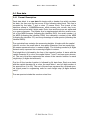
4.2.1 Parabolic Dish
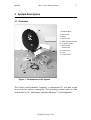
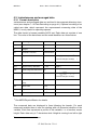
The antenna is used for the transmission of the RADAR signals and the receiving of backscattered signals. It is designed as an offset parabolic dish (1).
Its largest diameter is 70 cm, the beam width is 2°. Due to the offset-design of
the parabolic dish rainwater can drain off.
For antenna mounting the tube socket (10) (inner Ø = 49.4 mm, outer Ø = 54.4 mm) is to be plugged onto a pole with an outer diameter of max.
49 mm. The socket is fastened with an M10 screw (10 mm Ø).
Connect a ground wire to this screw which serves as a surge protector.
The pivot (9) is factory-adjusted, so that vertical orientation of the mounting
tube socket results in a vertical orientation of the antenna beam. (Ignore the
scale on the pivot).
The parabolic dish must not be moved in its pivot (9), because this
would cause beam deviations from vertical and would result in erroneous measurements.
The transmitting and receiving properties of the antenna affect the radar calibration. Therefore the reflector surface should be clean (e.g. free from leaves
or wet snow). For the same reason any mechanical deformation of the parabolic dish must be avoided. If nevertheless obvious deformation occurred, the
reflector must be replaced.
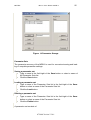
4.2.2 Antenna Heating (Option)
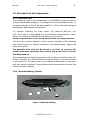
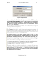
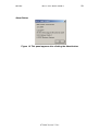
Figure 2 Antenna Heating
07.2009 Version 5.2.0.1