1
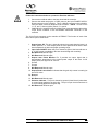
2. Pin 2 of the Control Interface is a LASER ON/OFF input. It is internally
pulled high, in which state the laser is prevented from operating.
Connecting Pin 2 to GND (Pin 11 and/or Pin 12 of the Control Interface
connector) will cause the laser to turn on. An interlock loop from Pin 2 to
the selected ground pin(s) (Pin 11 and/or Pin 12) when interrupted, will
cause an immediate shut down of the laser current. An interlock jumper
plug is provided with the system to allow operation without an external
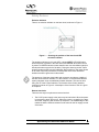
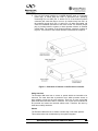
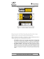
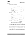
control cable. The location of the Control Interface connector is shown in
Figure 2. The function of the Control Interface is described in Chapter 4.
Figure 2: Illustration of features on the Excelsior controller.
Safety Interlock
The Excelsior-488 laser has no covers or panels which are intended to be
removed. The laser head has a protective cover which prevents access to
laser radiation except via the laser aperture. There are no user serviceable
parts inside either the laser head or controller. The covers are not intended to
be removed and cannot be removed without tools. Therefore, the laser by
itself has no safety interlocks.
Shutter
The Excelsior-488 laser has no shutter or beam stop on the laser aperture.
This must be taken into consideration by the system integrator.
Spectra-Physics Excelsior-488 User Guide
10