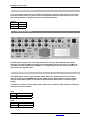
1
Operation Manual
Scorpius Digital On Air Console
Version
1.0.0.9
Dear Customer,
Thank you for choosing the SCORPIUS digital On-Air mixing console.
The Scorpius is designed by specialists in the field of radio broadcast and designed to be used
as a 24-hour "On-Air" console.
This time you are not faced with a huge manual because it is simply not necessary because of
the natural recognition of all functions on the user interface. All functions are self-explanatory
and you will certainly appreciate the ergonomics of this design. No digital layering just direct
access to all relevant functions, as we think it should be in daily practice
Jan Betten and Anton Prins both equally responsible for the design of the Scorpius always
value suggestions from you once you have become familiar with your console.
We will certainly learn from your comments, and we will very much appreciate the effort and
time it will take for you to communicate your idea’s and suggestions.
We are confident that you will be using the Scorpius for many years to come, and wish you a
lot of success.
With kind regards,
Duco de Rijk
PRESIDENT
D&R ELECTRONICA WEESP B.V.
Rijnkade 15B
1382 GS WEESP-HOLLAND
The Netherlands
Phone: 0294-418 014
Fax: 0294-416 987
Website: http://www.d-r.nl
E-mail: [email protected]
Scorpius Digital Mixer from D&R Phone +31 294 418014, email: [email protected] Page
2
Contents
1
INTRODUCTION ...........................................................................................................................5
2
ENVIRONMENTAL RECOMMENDATIONS.................................................................................6
3
CONTENTS OF THE PACKAGE ..................................................................................................7
4
WHY THE SCORPIUS IS A DIGITAL CONSOLE ........................................................................7
5
ANALOG/DIGITAL LEVELS WITH THE SCORPIUS ...................................................................8
6
SYSTEM STRUCTURE.................................................................................................................9
6.1
6.2
6.3
7
USER-INTERFACE ....................................................................................................................9
INPUT/OUTPUT CONNECTIONS ...................................................................................................9
SOFTWARE ..............................................................................................................................9
HARDWARE CONNECTIONS ....................................................................................................11
7.1
ANALOG IN-/OUTPUTS ...........................................................................................................12
7.1.1 MIC inputs......................................................................................................................12
7.1.2 LINE inputs ....................................................................................................................13
7.1.3 Program outputs ...........................................................................................................13
7.1.4 Sub outputs ...................................................................................................................13
7.1.5 CUE outputs ..................................................................................................................13
7.1.6 AUX. outputs .................................................................................................................14
7.1.7 CRM outputs..................................................................................................................14
7.1.8 Studio outputs...............................................................................................................14
7.1.9 Talkback output ............................................................................................................14
7.1.10
External inputs..........................................................................................................14
7.1.11
Announcer / Guest outputs .....................................................................................15
7.2
DIGITAL IN-/OUTPUTS ............................................................................................................15
7.2.1 Digital in/output 1-6 ......................................................................................................15
7.2.2 Digital in/output 7- 8 .....................................................................................................16
7.3
GLOBAL IN-/OUTPUTS ...........................................................................................................17
7.3.1 Word clock out ..............................................................................................................17
7.3.2 Word clock in ................................................................................................................17
7.3.3 Global GPIOs.................................................................................................................17
7.3.4 Meter connection ..........................................................................................................18
7.3.5 On-Air 1/2.......................................................................................................................18
8
AUDIO SIGNAL PATH ................................................................................................................19
8.1
8.2
8.3
9
INPUT MATRIX ........................................................................................................................19
BUSS STRUCTURE .................................................................................................................19
OUTPUTS ..............................................................................................................................19
PROCESSING .............................................................................................................................20
9.1
INPUT PROCESSING AND ROUTING ...........................................................................................20
9.2
EQ .......................................................................................................................................21
9.3
DYNAMIC RANGE CONTROL .....................................................................................................22
9.4
LEVEL AND ROUTING .............................................................................................................22
9.4.1 Aux. buss.......................................................................................................................22
9.4.2 Program/Sub buss ........................................................................................................22
9.4.3 CUE buss .......................................................................................................................22
9.4.4 Fader ..............................................................................................................................22
9.5
MASTER AND CRM FUNCTIONALITY ........................................................................................23
9.5.1 Clock and Timer ............................................................................................................23
9.5.2 Master functions ...........................................................................................................23
9.5.3 Master meters................................................................................................................24
9.5.4 CRM................................................................................................................................24
9.5.5 Studio.............................................................................................................................24
9.5.6
10
Master level controls ....................................................................................................24
THE SOFTWARE ........................................................................................................................25
10.1
GLOBAL SETTINGS .................................................................................................................26
10.1.1
Frequency .................................................................................................................26
10.1.2
Metering.....................................................................................................................26
10.1.3
Aux pre/post..............................................................................................................27
10.1.4
CUE set-up ................................................................................................................27
10.1.5
Source Selection ......................................................................................................28
10.1.6
EQ Range ..................................................................................................................28
10.1.7
Auto save ..................................................................................................................28
10.1.8
Swap EQ ....................................................................................................................28
10.1.9
Masterfader ...............................................................................................................28
10.1.10 Clock Setup ...............................................................................................................29
10.1.11 Remote 1 … 4............................................................................................................29
10.2
INPUT AND OUTPUT SET-UP.....................................................................................................30
10.2.1
Input set-up ...............................................................................................................31
10.2.2
Input settings ............................................................................................................31
10.2.3
Remotes out (GPIOs) ...............................................................................................31
10.2.4
Input active generates: ............................................................................................32
10.2.5
MIC to digital input set-up .......................................................................................32
10.2.6
Cleanfeed input set-up.............................................................................................33
10.2.7
Stereo line input set-up............................................................................................33
10.2.8
Stereo digital input set-up .......................................................................................33
10.2.9
Stereo digital output set-up.....................................................................................33
10.3
MACRO SWITCH SET-UP ........................................................................................................34
10.4
OPERATING LEVEL SET-UP .....................................................................................................34
10.5
SMART-CARD DATABASE ........................................................................................................36
10.6
SNAPSHOTS AND PRE-SETS ....................................................................................................37
10.6.1
Total snapshots ........................................................................................................37
10.6.2
EQ pre-sets ...............................................................................................................37
10.7
SOFTWARE MAINTENANCE .....................................................................................................38
10.7.1
Software upgrade .....................................................................................................39
10.7.2
Restoring the Console .............................................................................................39
11
TROUBLESHOOTING ................................................................................................................40
12
FREQUENTLY ASKED QUESTIONS.........................................................................................41
13
SPECIFICATIONS .......................................................................................................................42
14
DISCLAIMER...............................................................................................................................48
Scorpius Digital Mixer from D&R Phone +31 294 418014, email: [email protected] Page
4
Introduction
1 Introduction
This manual will give you a detailed explanation of the functionality of the Scorpius and all its
features.
It is advised to read this manual once before touching any control, or even thinking about hooking
up the system.
I know that that is actually the firsts thing you want to do but please do NOT and discipline
yourself to read the manual first.
The manual gives all sorts of valuable information before getting started and it saves you from
getting in touch with us for all sorts of questions. You can use this manual later on as a reference.
In the first chapters we shall try to give an overview of the Scorpius and its features. In this way
you can have an impression of how to implement the system in your application.
The next chapters will deal with interconnecting the various parts of the system and its external
interfacing with your equipment
When the Scorpius is installed and wired, you can finalize its interfacing with the instruction in the
following chapters.
After having installed the Scorpius you will have a very complete ON-AIR mixer with a human
interface that is very logical and understandable by intuition.
Scorpius Digital Mixer from D&R Phone +31 294 418014, email: [email protected] Page
5
Environmental recommendations
2 Environmental recommendations
The Scorpius console is a digital console. Digital equipment can be more sensitive to ESD
discharges then analog devices. Whereas on an analog device you only hear a spike in the
audiosignal, on the digital device you can mess up the control-logic inside the console which can
lead to a non-responding console.
The Scorpius console is protected according to CE regulations against discharges of any kind.
There is always the possibility that a discharge occurs on a higher level then specified in the CE
regulations. this can result in a non-functioning console.
To avoid these circumstances there are a number of environmental recommendations
available.
1)
Use ESD (Electric Static Discharge) safe carpeting. There are 2 kinds of ESD safe
carpeting available.
A conductive carpet; This is a special conductive carpet placed over an earthed
copper wire network. The copper wire network should be earthed to the mains
earth point with a 1 mega Ohm resistor. For example, Heugafelt, a carpet
manufacturer, is supplying this in a “ tile form” or as a carpet.
Non-charging carpet; This carpet doesn't charge itself when walked on. This
means that the persons who walk on the carpet don't charge either so they can't
discharge themselves on a console.
2)
A second very well considerable extra creator of static electricity is the synthetic
coverage used on chairs. There are several chair brands offering chairs with a
conductive seat and back earthed with a 1 mega Ohm resistor and conductive wheels.
3)
In any case make sure that all of the devices in a studio are properly connected to a
common ground!!
Scorpius Digital Mixer from D&R Phone +31 294 418014, email: [email protected] Page
6
Contents of the package
3 Contents of the package
If everything is right the following part should be inside the Package.
1)
2)
3)
4)
5)
6)
7)
8)
9)
10)
11)
1 Scorpius console
1 Full version of Microsoft Windows NT 4.0© including Servicepack 6a
1 Scorpius V1.0.0.X CDROM including (this) usermanual and Servicemanual
1 Chipcard
1 Powercord
1 PS/2 splitcable Keyboard/Mouse
1 IDE cable
1 ARBOR Single Board Computer Driver CDROM
1 Manual for the ARBOR Singleboard Computer
1 ARBOR Warrantee certificate
1 Parallel port/RS232 extension bracket
4 Why the Scorpius is a digital console
Digital audio is slowly accepted as the new standard for audio. The Scorpius has a design based
on a new generation of software for mixing consoles with Digital Signal Processing. The Scorpius
is designed using the latest available technology in its field and its design simply bypasses all
other older digital design techniques.
The Scorpius accepts all digital audio sources without any loss of quality. Use of sample rate
converters on all inputs simply eliminates all the problems related to different sample frequencies
in older digital desks.
You can virtually connect any of today’s digital and analog sources to the Scorpius.
In the digital domain there are even more advantages, such as reproducing and copying signals
without any loss of quality. Patching on a patch-bay has also become a thing of the past, since the
built in digital router takes care of this task.
All processed data throughout the whole system is in floating point format. This results in infinite
headroom! This means that, when applying extensive EQ, like boosting wide frequency bands, the
signal level is allowed to exceed the 0dB limit. Traditionally this would result in digital overload
and clipping. Due to the floating point principle the audio data in the system remains unaffected.
Simply lowering the output level of your channel can compensate the clipping-effect. Keep in mind
that this is not a case of restoring data. The clipped data never got distorted, but just exceeded the
bit range of the D/A-converters. The same thing applies for an overdriven mix-buss. For your
information, the (expensive) floating-point technique is only used in state-of-the-art digital
systems.
Digital technology allows a lot of extra features to be implemented. No outboard dynamicprocessors are required since the Scorpius features its own dynamic range control on every
individual input channel.
And the most exciting feature of the Scorpius is that every parameter on front panel can be stored
and retrieved later. You can build your own library of snapshots and pre-sets and save them on
hard disk or floppy.
Digital technology shall give you and your facility more flexibility and more power than you have
ever experienced in the analog domain. Reliability is guaranteed by using the industrial standard
Windows NT© operating system. Utmost attention has been given to the aspect of reliability,
equally reflected in hard- and software.
Scorpius Digital Mixer from D&R Phone +31 294 418014, email: [email protected] Page
7
Analog/Digital levels with the Scorpius
5 Analog/Digital levels with the Scorpius
Before we can start working with a (digital) console we need to understand all level
standardization for the inputs and outputs. In the Analog domain it is sometimes confusing.
But now we have to deal with even more formats. Often we use the following parameters:
0 dBu
0 dBFS
Analog level of 0.775V at 600Ohm.
FS= Full Scale… means maximum digital value (=clip).
First we will give a simple example with a CD-player:
Your home CD player plays CDs, which are most of the time ‘normalized’.
In the mastering process the highest peak value is monitored and is than the 0 dBFs
reference. Like in most common players they use a standard where the maximum output
voltage is 2Vt-t, which means around +8 dBu.
An example in an analog system.
The analog-mixing console must have enough headroom to handle your audio with care.
An often-used standard of 20dB headroom is enough for most circumstances.
Those two examples show exactly the problem of combining the digital and analog world. We
would like to have headroom in our mixer because we are adding signals, but we don’t want
too much headroom because we ‘eat bits’ (20 dB headroom is more than 3 bits).
Like the AES (and Dolby) specified, D&R is using a standard of 0 dB in the console (on the
meter) is equivalent to –20 dBFs at the digital output. This means you have on your digital
outputs enough headroom! The 0 dB level on the meter is +6 dBu on the balanced XLR outputs.
Because you also need your bit-resolution we interface with 24 bits and process the signal with
32 bits floating point! This provides you with sufficient headroom.
For ease of use the console is also equipped with cinch inputs and outputs. It’s difficult to
specify a standard for this type of connector; this is because many manufacturers use different
values. When the console leaves the factory the Cinch outputs are trimmed to 0 dBu if the level
on the meter is 0 dB. That means if you connect a digital recorder with a maximum input of 2Vtt (for example a calibrated input) you still have 8 dB of headroom. Of course you will also find a
‘Record level’ on the most recording equipment.
If we now understand the current situation with the levels we still have to overcome some
problems. If we connect signals and the level seems not to be correct we can easily adjust the
gain on the control surface, this can instantly correct the problem.
But for digital inputs the level problem is more related to the medium. CD-players and MDplayers are most of the time playing a medium, which is normalized. That means if we should
connect it directly to the console we see an incoming signal of +20 dB !!!
Therefore you may set-up a ‘Source headroom’ for each digital input, so if you connect a CD
player to digital input 1 you can already set the source headroom to 0 dB in the input/output
set-up dialog. The Scorpius will then make a level correction for this medium.
Now you know how you can interface between the analog and digital world with understanding
of what is happening with your levels. We hope this chapter gives an insight on this matter.
0 dB on your meter is:
• +6 dBu on the balanced input/outputs
• 0 dBu on the unbalanced inputs/outputs
• –20 dBFs at the digital inputs/outputs.
Scorpius Digital Mixer from D&R Phone +31 294 418014, email: [email protected] Page
8
System structure
6 System structure
The Scorpius is a standalone console, which can be seen as a combination of several system
blocks, dedicated to a specific function. These building blocks are:
• The user-interface;
• The I/O connections;
• The software.
6.1 User-interface
The user-interface provides direct access to all-important parameters of a selected channel by
simply pushing the SEL(ect) switch. A complete channel strip is present in the center section of
the console and is active for the selected channel. Any change made here is instantly affecting the
audio path in the selected channel.
A simple step-by-step process can access all advanced functions. This allows working very fast,
without worrying about complex routines, or taking risk of loosing control. The result is a
transparent system that allows you to concentrate on being a DJ instead of being an engineer.
The 16-character-LCD display provides you with detailed and real-time information about which
source is selected as input signal of a channel. This assures you not to lose track of the signal
configuration by the router.
6.2 Input/output connections
The input and output connections are located at the backside of the Scorpius. This is where all
sound sources and outboard equipment are connected to the console. You can patch cables to any
physical input, as you like without having to worry about where this signal shall be processed later
on. The Scorpius has a full-cross point integrated router, offering you the same functionality as a
programmable digital patch-bay.
Also all GPIO (General Purpose Input/Output) are located at the backside of the mixer. These
GPIO’s can be used for controlling your studio equipment.
6.3 Software
All hardware configurations and settings are managed by software. The Scorpius can be
configured to meet any customer specific needs. Besides, by connecting a 1024x768 SVGA
computer screen (not included in the delivery) to your Scorpius, you will get real-time, visual
information about the current configuration. The screen enables you to monitor any signal by
means of two stereo PPM-meters. Moreover the software allows you to save and load settings from
a hard disk or floppy.
Scorpius Digital Mixer from D&R Phone +31 294 418014, email: [email protected] Page
9
System structure
Scorpius Digital Mixer from D&R Phone +31 294 418014, email: [email protected] Page
10
Hardware Connections
7 Hardware Connections
The Scorpius is designed to be installed easily. The design makes it possible to switch very
easy from your old analog console to this new digital console. All connections are standardized
connections (most of the time XLR), so there is no need for much soldering/wiring.
On the far right side of the back panel of the Scorpius you will see the mains connector and the
mains switch. Please make use of a grounded mains outlet when connecting the Scorpius to
the mains. But before you turn the Scorpius on make sure you have made the following
connections to the internal computer board located far right beneath the mains connectors.
From left to right you will see the following connectors;
1)
2)
3)
4)
PC2 (mini din) connector with external Y cable interface (included in the delivery) to
hook up a keyboard and mouse (not in the delivery)
RS232 9 pole male connector (not in use)
Ethernet (LAN) connector (not used).
VGA connector for connecting a (TFT) screen (a screen is not included in the
delivery)
After having connected all the above devices (mouse/keyboard/screen) you can turn on the
Scorpius and wait for initialization of the software. Now you are able to use the console. To
make live easier it is possible to make a setting (eg. Input routing / EQ settings) and store it in a
file called ‘STARTUP.SCP’. This file is loaded when the mixer application is started.
Scorpius Digital Mixer from D&R Phone +31 294 418014, email: [email protected] Page
11
Hardware Connections
7.1 Analog In-/Outputs
The back panel of the Scorpius provides you with all the in and outputs of the console of which
you see the analog part below.
Most of the XLR connectors are self-explanatory and are wired balanced.
Pin1
Pin2
Pin3
7.1.1
Ground
Hot (in phase)
Cold (out of phase)
MIC inputs
The Scorpius has 6 MIC inputs, which are wired according to international standards. You are
able to trim the ‘pre gain’ of the microphone (you also have an analog gain digitally controlled
by software +/- 30 dB) before signal is applied to the insert. The standard level of the insert is 0
dBu.
Then there is a corresponding GPIO (General purpose input/output), which gives the possibility
for enhanced logic to this input.
NOTE: When connecting cables to the Mic inputs please first switch the Phantom power off to
avoid damage of the input amps!
Pin1
Pin2
Pin3
Ground
Hot (in phase)
Cold (out of phase)
Mic jack insert wiring is:
Tip
Send
Ring
Return
Ground
Shield
The Mic inputs have dedicated jack type of GPIO’s wired
Tip
5V, 8mA (capable of direct driving LED)
Ring
Switch
Ground
Shield
Scorpius Digital Mixer from D&R Phone +31 294 418014, email: [email protected] Page
12
Hardware Connections
7.1.2
LINE inputs
The Stereo line inputs have also XLR type of connectors for easy connection. The Levels are
standardized for +6dBu (or –10 dBV by jumpers inside). Furthermore you find at top of the
stereo pair a GPO. This GPO is wired to isolated relays capable of handling a maximum of 24
volt at 60 mA.
XLR :
Pin1
Pin2
Pin3
Ground
Hot (in phase)
Cold (out of phase)
GPO:
Tip
Ring
Ground
7.1.3
Center contact
Normally Open
Normally Closed
Program outputs
The Scorpius console has many connectivity options. An analog stereo program output plus a
dedicated MONO output. But that’s still not everything; there are also Cinch connectors, which
give the program signal.
The XLR connectors carry a standard level of +6 dBu and the Cinch connectors a level of 0
dBu.
XLR:
Pin1
Pin2
Pin3
7.1.4
Ground
Hot (in phase)
Cold (out of phase)
Sub outputs
The XLR Sub outputs are standardized at a level of +6 dBu. MONO sub and stereo Sub at XLR
is available and also a stereo Sub signal is at Cinch connectors. Those Cinch connectors adapt
a level standard of 0 dBu.
On the master section you can find a master controller for the Sub buss, which also controls
the level of the signal for all these outputs.
Pin1
Pin2
Pin3
7.1.5
Ground
Hot (in phase)
Cold (out of phase)
CUE outputs
The CUE buss has cinch connectors as dedicated outputs, which are at an unbalanced level of
0dBu. You can control the level of the CUE buss also at the master section of the Scorpius with
the CUE-level potentiometer. This output makes it possible to connect dedicated (active)
speakers
Scorpius Digital Mixer from D&R Phone +31 294 418014, email: [email protected] Page
13
Hardware Connections
7.1.6
AUX. outputs
The stereo AUX buss is on XLR connectors which adapts to the +6 dBu standard. This means
you can directly connect your equipment to the AUX outputs.
Pin1
Pin2
Pin3
7.1.7
Ground
Hot (in phase)
Cold (out of phase)
CRM outputs
The CRM outputs have a standardized level of +6 dBu, so you can directly connect it to your
Amplifier/Active speakers. On the master section of the console you have the possibility to
adjust the level of the CRM outputs and to select the source of the signal.
Furthermore there are options for ‘CUE to CRM’ and ‘CRM mute logic’, which makes it possible
to monitor various sources through your speaker system!.
Pin1
Pin2
Pin3
Ground
Hot (in phase)
Cold (out of phase)
7.1.8 Studio outputs
The STUDIO outputs have a standardized level of +6 dBu, so you can directly connect them to
your Amplifier/Active speakers. On the master section of the console you have the possibility
to adjust the level of the STUDIO outputs, and to select the source of the signal.
Furthermore there are options for ‘STUDIO mute logic’, which makes it possible to prevent you
from feedback of your studio room.
Pin1
Pin2
Pin3
7.1.9
Ground
Hot (in phase)
Cold (out of phase)
Talkback output
To give the Scorpius as much flexibility as possible you can find at the back panel a TB output.
You can use this output for your own TB/Communication systems. By a simple press of a
button at the master section you can send the signal from the internal MIC to this XLR.
Pin1
Pin2
Pin3
Ground
Hot (in phase)
Cold (out of phase)
7.1.10 External inputs
Of course you must be able to listen to the signal off air. Therefore you can use those external
inputs. At the cinch connectors (–10dBV but internally trimmable). When connecting your
source signals you can select your sources to the CRM or STUDIO buss at the master section.
Scorpius Digital Mixer from D&R Phone +31 294 418014, email: [email protected] Page
14
Hardware Connections
7.1.11 Announcer / Guest outputs
As in your analog console there are dedicated headphone outputs for the announcer and guest.
From the master section it is just one press of a switch to talk to the announcer or guest. This
gives the technician a useful tool to share all needed information.
JACKs:
Tip
Ring
Ground
Left
Right
shield
7.2 Digital In-/Outputs
All XLR digital in/outputs are wired fully balanced according to the standards of the AES3
standard. The internal 0dBu level inside the console adapts the nominal level of –20 dBFs (as
advised by the AES committee and Dolby). For all digital inputs you can setup the amount of
headroom in the applied signal.
7.2.1
Digital in/output 1-6
The digital inputs are structured like dual inputs. Within the software you can select which
input you want to use AES/EBU (XLR) or the S/PDIF (Cinch). Both outputs in a digital section
give the same output signals. In the software you determine which buss is send to a digital
output.
Furthermore is there for every digital input a GPO wired to isolated relays capable of handling a
maximum of 24 volt at 50mA
XLR:
Pin1
Pin2
Pin3
GPO:
Tip
Ring
Ground
Ground
Hot (in phase)
Cold (out of phase)
Center contact
Normally Open
Normally Closed
Scorpius Digital Mixer from D&R Phone +31 294 418014, email: [email protected] Page
15
Hardware Connections
7.2.2
Digital in/output 7- 8
The digital inputs are structured like dual inputs. Within the software you can select which
input you want to use AES/EBU (XLR) or the S/PDIF (Optical). These two outputs are optical
outputs for an isolated connection to your equipment. In the software you determine which
buss is send to a digital output.
Furthermore is there for every digital input a GPO wired to isolated relays capable of handling a
maximum of 24 volt at 50mA
XLR:
Pin1
Pin2
Pin3
GPO:
Tip
Ring
Ground
Ground
Hot (in phase)
Cold (out of phase)
Center contact
Normally Open
Normally Closed
Scorpius Digital Mixer from D&R Phone +31 294 418014, email: [email protected] Page
16
Hardware Connections
7.3 Global In-/Outputs
Those in-/outputs are use for global means. For example synchronization, metering, relay logic
etc…
7.3.1
Word clock out
For digital audio you need synchronization. Newer equipment uses most of the time sample
rate converters to be able to read digital audio. If you have equipment without this option you
can use the Word Clock output to get this equipment synchronized with the Scorpius console.
The BNC connector gives the word clock out at TTL Level (@ 75 Ohm)
7.3.2
Word clock in
Sometimes you need to synchronize your complete studio to the same clock. At that moment
you can see the Scorpius as a slave. Simply use the BNC connector of the word clock input to
slave to a word clock generated by other equipment. This input accepts TTL level (@75 Ohm).
7.3.3
Global GPIOs
You can assign in software global functions to the global remotes (GPIOs). These are functions
like Red-light, Timer, CUE Reset etc…
The Logic signals are interfaced via a male Sub-D 25 pole connector to isolated relays capable
of handling a maximum of 24 volts at 50mA.
Switch contact is called C(enter) C(ontact)
Normally closed contact is labeled N(ormally) C(losed)
Normally open contact is labeled N(ormally O(pen)
GPIO
Output
Input
#1
1
14
2
#2
4
17
5
#3
7
20
8
#4
10
23
11
Description
NC
NO
CC
15
3
16
18
6
19
21
9
22
24
12
25
Input (tied to ground generates an action)
Ground
Ground
Scorpius Digital Mixer from D&R Phone +31 294 418014, email: [email protected] Page
17
Hardware Connections
7.3.4
Meter connection
In case you have your own specific meters, which are already build-in into your studio, we
made it possible to connect meters to an external connector. All common signals are available
at this connector. Below you can find a table with the connections.
The Meter connections are interfaced via a Female Sub-D 25 pole connector.
Hot
Cold
Ground
7.3.5
Prog L
1
14
2
Prog R
15
3
16
Sub L
4
17
5
Sub R
18
6
19
Aux L
7
20
8
Aux R
21
9
22
CUE L
10
23
11
CUE R
24
12
25
On-Air 1/2
Of course the Scorpius has specific broadcast features. The Scorpius has two signaling
busses for Red-light. Those busses trigger a relay output, these are called ON-AIR1/2.
These jack type GPO’s are wired to isolated relays capable of handling a maximum of 24 volt at
50mA
Tip
Ring
Ground
Center Contact
Normally Open
Normally Closed
Scorpius Digital Mixer from D&R Phone +31 294 418014, email: [email protected] Page
18
Audio Signal Path
8 Audio Signal Path
The Scorpius is a digital On-Air mixer with incredible flexibility. It therefore is a necessity to fully
understand the Scorpius’ potentials and this manual will try to give you a clear picture of all the
features available in this mixer.
It is possible to connect a total of 24 input sources and several dedicated outputs to this mixer. As
is standard practice in the professional digital audio industry, there is no direct physical
connection between the input source and the input modules on the control surface.
It is therefore advisable to clearly label all the cables connected to the I/O connections to avoid
misunderstanding.
Furthermore, you can send any audio signal to several busses and use the CRM and STUDIO
section for convenient monitoring.
8.1 Input matrix
The Scorpius gives you the option of routing any or all of the 24 inputs (stereo or analog) to any
module input of the control surface.
The Scorpius offers you a 32 to 16 stereo input router to connect the audio sources to any of the 16
input channels.
The master section features dedicated CRM and STUDIO outputs, which also enables you to swap
the CRM or STUDIO with 2-Tracks and much more broadcast specific functions.
.
8.2 Buss structure
As mentioned before, every input channel features EQ- and dynamic processing. This is why these
channels are often referred to as ‘processing’ channels.
The output of the 16 stereo processing channels audio can be routed to different busses.
Busses that are available are;
•
•
•
•
Stereo PROGRAM buss.
Stereo SUB buss.
Stereo AUX. Buss.
Stereo CUE buss.
The 6 CRM sources (Prog, Sub, Aux, CUE, Extern 1, Extern 2) may be summed into the CRM buss.
The 6 Studio sources (Prog, Sub, Aux, CRM, Extern1, Extern 2) may be summed into the Studio
buss.
8.3 Outputs
The Scorpius uses dedicated outputs for your Prog, Sub, Aux, CRM and Studio. This eliminates the
risk of accidentally rerouting the program or monitor busses while On-Air.
For digital recording equipment you are able to send the Prog, Sub, Aux or CUE buss to the digital
outputs.
Scorpius Digital Mixer from D&R Phone +31 294 418014, email: [email protected] Page
19
Processing
9 Processing
It is possible to process 16 stereo channels in parallel. Every processing channel handles input,
EQ, dynamic range control, level and output selection.
Now we shall give you a global overview of the Scorpius digital mixer. All hands on features
described here can be found on the main screen of the system. Just like in any analog system.
9.1 Input processing and routing
The input signal can be processed as soon as it is converted into the digital
domain. Specifying an input source for the channel does this. By clicking on the
selection box “N.C.” ( “Not Connected”). A pop-up menu will appear, showing all
the input sources available. Select the source required and the system will handle
the audio routing.
Then you have the option of using the stereo processing channel as a mono
channel. Both left and right input signal will be added, compensated in level, and
routed to the left and right output of the processing channel.
When you are ready selecting the input sources you need for the job, you can trim the input level
within a range of 40 dB (-20dB to +20dB) by adjusting the gain control. This can either be done in
software on screen or on hardware level by means of gain knob on the console.
For the MIC input you are directly controlling the MIC-gain in the analog domain (pre AD) so you
may prevent clipping. For the MIC channels your range is -30 dB to +30 dB
NOTE: When connecting cables to the Mic inputs please switch the Phantom power off to avoid
damage of the input amps!
NOTE: The current module should be selected by pushing the ‘SEL’ button on the front panel.
Scorpius Digital Mixer from D&R Phone +31 294 418014, email: [email protected] Page
20
Processing
9.2 EQ
The Scorpius has a three band, fully parametric Equalizer.
The HF band is always shelving.
The MF band is always bell curved.
The LF band functions with ‘shelving’ when it attenuates and its curve will be ‘bell
shaped’ when your level is above 0 dB.
All bands have adjustable level, frequency, and bandwidth with absolute values
written in real-time on the screen. The controls high, mid and low on the front panel
give you direct access to the three band levels of the EQ. By double-clicking on the
small EQ graph, the EQ window will appear. The EQ window provides overall control
over the channel’s EQ section. From this window you can adjust band level (gain),
frequency and bandwidth.
By doing a double click on the EQ window
you get an enlarged view. This EQ window is
a very powerful editing feature. The curvedisplay gives a true and real-time image of the
overall effect of the EQ settings. Because it’s
an interactive curve-display, changing the
location of the bullets in the graphic display
can modify the EQ settings. The bullets can
be moved by a simple click en drag action.
NOTE: Pushing the EQ knobs return the EQ
level controls to there zero (mid) positions.
The EQ button at the bottom of the window is
overall EQ on/off switch.
Scorpius Digital Mixer from D&R Phone +31 294 418014, email: [email protected] Page
21
Processing
9.3 Dynamic range control
Every channel has a dynamics controller, which enables you to control the dynamic
range of the present audio signal. Actually it is a very intelligent, automatic
compressor/limiter. The amount of dynamic compression is set by just one control.
This allows you to make “on the fly” adjustments without having to worry about
ratio’s and thresholds. A reduction in dynamic range is exactly what you get.
When turning the control anti clockwise, no dynamic changes take effect. In turning the control
clockwise more dynamic control takes place. Mind that the amount of effective gain reduction is
related to the level of the input signal. When pushing the control knob the dynamic control returns
to its non-effective position, as if it was fully anti-clockwise.
The button labeled ‘Dyn’ is an on/off switch for the dynamic range control
9.4 Level and Routing
When the signal has been processed in EQ, dynamics range and level it can be routed to one or
more than one busses such as the Aux. buss, Program buss, Sub buss and the stereo CUE buss.
A description of individual output busses is written below.
9.4.1
Aux. buss
The Scorpius has one stereo AUX. buss. This buss accepts signals from the input
module pre or post fader, depending upon your selection.
Every Aux. send can be adjusted in level.
9.4.2
Program/Sub buss
The Scorpius has a stereo Program and Sub buss implemented. These are accessible
through Program and Sub switches. This signal fed to the program and sub buss is
always post fader.
The Pan control adjusts the balance between the signal going to Prog/Sub left and
Prog/Sub right
9.4.3
CUE buss
The stereo CUE buss can be fed from one or more processing channels by way of the Cue
switches on the console or at the computer screen. The signal from the processing channel to the
CUE buss is routed pre-fader.
An alternative function of the CUE buss is to use it as a talkback communication switch, explained
later on in the manual.
9.4.4
Fader
The Fader is used to set the level of the processing channel before it is fed to the PROG and Sub
busses.
Scorpius Digital Mixer from D&R Phone +31 294 418014, email: [email protected] Page
22
Processing
9.5 Master and CRM functionality
This broadcast mixer has extensive monitoring and master features. You have a Clock, a Timer,
ON-Air indication (on the SVGA screen), assignable meters and CRM source selection. All these
functions are located in the upper section of the display as shown below.
9.5.1
Clock and Timer
Situated left in the master section there is an analog type clock producing the actual time. The next
section houses the Timer and its controls. This precision Timer is accurate down to 1/10 of a
second. The Timer can be activated by clicking the Start button or by assigning the Timer to a
fader-start (see 10.2 Input and output )
The Stop knob stops the Timer when started by the Start knob or fader-start.
The Reset always sets the Timer to 00:00:00:00
9.5.2
Master functions
The red light control is located in the master section. It is located below the Clock on the screen.
The ‘ON-AIR’ light shall only be activated when a channel, that is set to generate red light (see 10.2
Input and output ), is activated.
NOTE: Red light signaling controls both the Red-light 1 and Red-light 2 buss-signals, however both
busses can be assigned individually to the Redlight1 and Redlight2 remotes.
Below the Timer you see a section, which shows you the name of the current ‘Chip card user’
Scorpius Digital Mixer from D&R Phone +31 294 418014, email: [email protected] Page
23
Processing
9.5.3
Master meters
The master meters are situated in the middle section. These meters always represent the signal
level assigned to the selected output buss. By clicking on the name of the meter a pop-up menu
will appear. Here you can select the signal shown by the meters. Selection options are: Prog, Sub,
Aux, CUE and Cleanfeeds.
NOTE: The meter screen can be seen in full scale by hitting the space bar and in the ‘Global
Settings’ menu you may select different meter types.
9.5.4
CRM
On the far right is the CRM section. This section determines what is sent to
your Control Room Monitors. You can select out of 6 stereo sources.
The knobs of the CRM can function in two ways. Additive or alternating,
depending on the settings made in the ‘global settings’ menu (see 10.1.5
Source Selection). Of course you have the possibility to adjust the level,
dimming and muting on the CRM buss, these knobs are all located in the same
area.
‘CRM Dim by TB’ Makes sure that the CRM’s will be disabled when making use
of the TB function.
9.5.5
Studio
You can select out of 6 stereo sources that are labeled.
You can select the source you want to listen to by the buttons in the studio
sections. These knobs can function in two ways. Either additive or alternating,
a decision made in the ‘global settings’ (see 10.1.5 Source Selection).
This section determines what is output to your Studio Monitors. ‘Mute disabled’
makes sure that the studio monitors no longer will be disabled when putting a
channel online.
9.5.6
Master level controls
You can change the master level of the Aux. and Sub buss with the
corresponding controller. To avoid accidental level changes, the ‘0 dBfixed’ function can be activated. This function bypasses the controller
knob and keeps the level set to 0 dB.
Scorpius Digital Mixer from D&R Phone +31 294 418014, email: [email protected] Page
24
The Software
10 The Software
The Scorpius is totally software-controlled mixer. It means that all data, either audio or control, is
digitally processed and the control data can be saved on hard disk, floppy or any other means of
storage device. The software-based character of the Scorpius ensures the console to be
configured to customer’s specifications. The configuration is an extremely simple process of
pushing buttons. Set-ups can be configured in any way you like. It is however important to
carefully program this personal set-up, to benefiting from repeatable pleasure.
It is advised to get familiar with all the software options that are built into this design.
The scorpius software runs on Microsoft Windows NT4.0© updated with the latest SP6a
servicepack in ensure maximum stability.
Warning: The write behind cache of Windows NT© is disabled so you don’t have to shutdown
windows the traditional way. You can just use the powerswitch located on the rearside of the
console to switch it of. Never do a warm reboot because the PCI-board inside de PC will refuse to
boot up again.
The Software can be divided in several building blocks:
1)
2)
3)
4)
5)
6)
Global settings
Input and output set-up
Macro set-up
Operation Level Setup
Smart-card Database
Snapshots and pre-sets.
The first two blocks are intended for one-time only personal programming. Block 3 is intended for
daily use. It can be seen as the main screen-display, providing total overview instantly.
Directory structure
When the Scorpius software is installed on your system you will be presented with a number of
traditional Windows NT© directories (normally this should be C:\Program Files\D&R Electronica
B.V.\Scorpius). Such as:
Dynamics
EQ
Firmware
Projects
This directory is the location for saving your dynamics presets.
This directory is the location for saving your EQ presets.
This directory contains the individual software components of the
Scorpius. It is only accessed during an ‘update embedded software’). This
software is only required during software updates.
This directory is the location for saving snapshots. It is however advisable
to create several new files for individually saving personal snapshots.
Note: The default snapshot ‘Startup.scp’ is always located in the
installation directory of the Scorpius (normally it is C:\Program Files\D&R
Electronica B.V.\Scorpius).
Note: Keep in mind that all directories and files are accessible by all users.
Scorpius Digital Mixer from D&R Phone +31 294 418014, email: [email protected] Page
25
The Software
10.1 Global settings
All global settings can be found in a sub menu called “global settings’. You can access this menu
via the main-menu-item SETUP. Clicking on this option opens up a window allowing you to change
specific hardware settings.
The next chapters will discuss the individual global programming blocks on the screen.
10.1.1 Frequency
This is where you can set the sample-rate of the entire system. All digital
outputs will be synchronized to this sample-rate. These settings have no
effect on the digital inputs since all input converters are provided with
their own dedicated sample-rate converters. You can choose common
formats such as 32kHz, 44.1kHz or 48kHz or External.
External means you use the word clock input. This makes it possible to
adapt to clocks of other equipment. When this clock is removed the
system will automatically go back using internal 48 kHz.
10.1.2 Metering
The release control allows you to adjust the release time of all meters of
the Scorpius.
Further you may select different meter types which the popup menu
which appears if you click on the meter type box. It is possible to select
Analog PPM, Digital PPM, BBC PPM and a Analog PPM with a clock.
Scorpius Digital Mixer from D&R Phone +31 294 418014, email: [email protected] Page
26
The Software
In the figures below you get a impression of the selections you can make:
Analog
Digital
BBC
Analog+Clock
10.1.3 Aux pre/post
The AUX buss can be pre or post
fader, this setting is made global
for all modules.
10.1.4 CUE set-up
The CUE set-up determines the functions of the Cue switch.
When Auto CUE reset is activated, all CUE settings are reset the
moment you activate a CUE on a channel. NOTE: this requires the Cuereset function, in the local input sections, to be active! (See 9.2 Input
and output )
Scorpius Digital Mixer from D&R Phone +31 294 418014, email: [email protected] Page
27
The Software
The Cue to CRM function allows you to use only one pair of speakers for both CRM and Cue
Monitoring. When the CUE to CRM is active, the CRM-buss signal will not be replaced by Cue
signal, but both signals shall be added on the CRM-bus. The level of the CRM signal can be
attenuated before addition. The amount of attenuation is set by the DIM control on the faceplate of
the Scorpius.
When CUE to CRM is inactive, the Cue signal is output to the Cue speakers, while the CRM signal
is continuously output to the CRM speakers.
10.1.5 Source Selection
This is the location where the interlock mode can be set. When this
option is set to “interlock” it is only possible to listen to one CRM
source at a time. But when deactivated, a summing of different CRM
sources can be realized. The same option for the Studio input
selection is available.
10.1.6 EQ Range
With this section you can adjust the range of the EQ level knobs. This
makes it possible to give your operators as much control as you want to
give them.
10.1.7 Auto save
The auto save function stores at fixed intervals the current
information to the ‘Backup.scp’ snapshot. Even when you disable
the Autosave the Scorpius will store all information to the
‘Backup.scp’ when you do a file open, file save or exit the
application.
When you restart the Scorpius it will first load the ‘Backup.scp’ if it exists. So you are sure you
getting back with the latest information ! If you want to make sure meanwhile backups are created
you can use this AutoSave feature.
10.1.8 Swap EQ
The ‘Swap EQ’ function let you swap the ‘EQ Low’ and the ‘EQ High’ rotary located
on the mid-top of the frontpanel.
10.1.9 Masterfader
The masterfader section gives you the option to use one of
the 16 faders as a masterfader. All channel function will be
disabled except panning.The ‘Redlight buss masked by
masterfader’ function gives you the ability to override
any redlight buss activity by the masterfader. In other words.
If a masterfaderchannel is closed or off, the redlight buss can’t be used by other channels.
Scorpius Digital Mixer from D&R Phone +31 294 418014, email: [email protected] Page
28
The Software
10.1.10 Clock Setup
The Clock Setup section gives the option to hide or show de date or time
present within the analog clock.
10.1.11 Remote 1 … 4
In the remote section setting can be made
regarding the Global GPIO’s located on the
rearside of the console. See also section 6.3.3.
Remote In
Momentary - determine the action to be
momentary or latching.
Cue reset - Gives a CUE reset at Remote In puls
Redlight 1 … 2 - Activates Redlight 1 or 2 at
Remote In puls
Timer - Starts the timer at Remote In puls.
Remote Out
On pulse - Gives an On pulse when triggered.
Off pulse - Gives an Off pulse when triggered.
Continues - Copies the status of the triggersource.
Redlight 1 … 2 - When the one of the Redlight busses activates, remote out will be triggered.
Timer - Triggers the remote out when timer starts or stops. Depending on what kind of action is
required
Master On – Triggers the remote out when master channel is switched on/off.
Master Fader On – Triggers the remote out when the masterfader opens or closes.
Master Fader On and ON - Triggers the remote out when the master channel is switched on/off and
when the masterfader opens/closes.
Macro 1 … 3 - Triggers the remote out when macroswitch 1, 2 or 3 is used.
Scorpius Digital Mixer from D&R Phone +31 294 418014, email: [email protected] Page
29
The Software
10.2 Input and output set-up
This chapter describes the initial set-up options of the inputs and outputs. It is a very important
part of the initial installation procedure of the Scorpius. This is where for instance the label and I/Ohardware settings are set-up. Carefully read and maybe re-read this section until you are fully
aware of all its do’s and don’ts.
To pull up the SETUP-menu you select the item ‘Input/output set-up’. The left side of the window
contains the inputs and the right side the outputs.
Scorpius Digital Mixer from D&R Phone +31 294 418014, email: [email protected] Page
30
The Software
10.2.1 Input set-up
You can directly enter a label into the input box. This is actually the
name representing the input source connected to that specific input
connector. All labels typed here are instantly shown on every display
related to this input. This makes it very easy to recognize the input
source later on.
10.2.2 Input settings
The ‘input settings” box has four more settings directly related to this
input.
EQ active
Dynamic range control active
Here you can decide to activate the EQ
section or keep it permanently
disabled.
Here you can decide to activate the
Dynamics section or keep it permanently
disabled.
When choosing EQ/dynamics inactive, the EQ/dynamics of any processing channel will
automatically be disabled whenever this input source is selected as input for the processing
channel
The ‘module switch function’ determines the functionality of the ‘ON switch’. When you select
ON/OFF it will function like a normal ON/MUTE switch which enables/disables audio.
If you select the Start remote, this switch will not enable/disable audio but only generate a ‘Start
remote’. The knob will light when the fader is open so the indication is the same if with the
‘ON/OFF’ situation: “On-switch lit and fader open is audio”.
10.2.3 Remotes out (GPIOs)
This section is not available for all inputs. The MIC inputs have dedicated
outputs for remotes so these options do not apply for MIC-inputs. This is
why the MIC channels do not have a Remote out selection box.
All the other inputs types will have this box shown, allowing you to
assign a specific function to the remotes out.
Remote types:
These settings determine the behavior of the remote.
On pulse
This will give a pulse on the remote relay when activating
the remote of the channel where this input is assigned to.
Off pulse
This will give a pulse on the remote relay when
deactivating the remote of the channel where this input is
assigned to.
Continues
This makes the remote relay copy the status of the remote
of the channel where this input is assigned to.
Activating the remote:
These settings determine which action activates the remote.
On switch
The state of the On switch is used for the remote generation.
Fader on
The state of the fader (open or closed) is used for the remote generation.
Fader on & On This is a combination of both the ‘On switch’ and ‘Fader on’ function. When the On
switch is active and the fader is open, only then the remote will be generated.
CUE
The state of the CUE switch is used for the remote generation.
Scorpius Digital Mixer from D&R Phone +31 294 418014, email: [email protected] Page
31
The Software
All these remote functions may be used for Start control or connection to radio automation
systems. Often is talked about GPIOs (General Purpose Input/Outputs).
10.2.4 Input active generates:
When an input is active (fader up and On active) several activities
can be programmed to be carried out.
Functions such as:
Red-light 1
Red-light 2
Timer
Control room mute
Studio mute
Local CUE reset
Total CUE reset
when the module is active red-light 1 buss
is activated.
when the module is active red-light 2 buss
is activated
when the module is active the Timer
(buss) is activated.
when the module is active the CRM mute
buss is activated. In this way CRM
speakers can be muted (Note: only when
you have programmed the output mutes to
be controlled by the CRM mute buss)
when the module is active Studio 1 mute buss is activated. In this way
Studio 1 speakers can be muted (Note: only when you have programmed
the output mutes to be controlled by the Studio 1 mute buss)
when the module is active, CUE of the related channel shall be switched off
when necessary.
when the module is active, CUE off all channels shall be switched off, so
the CRM can monitor the broadcast directly.
10.2.5 MIC to digital input set-up
The level of the MIC input can be adjusted with a small trimmer,
which is on the backside of the console near the XLR.
Also the Phantom power switch (+48V) is located near the XLR
socket on the backside.
NOTE: When connecting cables to the Mic inputs please switch
the Phantom power off to avoid damage of the input amps!
In Software you can give also a digital controlled analog gain with
the potentiometer. Further you can make here several settings
the “Input settings” and “Input active generates” like explained
before.
The incoming remote will be a COUGH/Talk-back function (switch-able on/off)
The outgoing remote will be MIC-ON for this MIC.
Scorpius Digital Mixer from D&R Phone +31 294 418014, email: [email protected] Page
32
The Software
10.2.6 Cleanfeed input set-up
On the backside of the console you can find 2 mono Line inputs
with a corresponding Clean-feed output. These inputs/outputs are
the N-1 for connection to a hybrid.
The Auto Talkback feature makes it possible to talkback to the
Hybrid output if you hit the CUE function for the channel.
You have the ability to set the “Input settings”, “Input active
generates” and “Remotes out”. The remote out enables you to
send GPIOs to the Hybrid. Default, the remote will generate a
continuous signal equal to the ON-switch.
10.2.7 Stereo line input set-up
The stereo line in is used to connect standard equipment with analog outputs.
You are able to program the “Input settings”, “Input active generates” and “Remotes out”. The
Remotes out enable you to program Fader and/or Switch start.
10.2.8 Stereo digital input set-up
In the upper right corner you find general selection options for
the connected I/O boxes. The stereo digital inputs can be set to
AES/EBU or S/PDIF. Furthermore you have the ability to swap the
left and right channel.
The UP/DOWN counter makes it possible to select the headroom
at the digital source material. When given this amount of
headroom the Scorpius will automatically adjust the source level
to the internal 0 dB level. (for CDs you have normally to assign 0
dB headroom).
10.2.9 Stereo digital output set-up
In the upper right corner the output source selection of the D/D unit
is located.
The source of the digital output can be selected in the small box.
You are able to select from Prog, Sub, Aux. and CUE.
Next you can select the data format of all outgoing digital audio
data. This can be in professional (AES/EBU) or consumer (Coax and
Optical) format. When you have selected the pro status Copy-bit
and Original are disabled.
Consumer mode re-enables the Copy-bit and original options.
Activating the dither function applies Dither on the output stream.
The final option is “Swap LR”. Left and right channels are swapped
before.
Scorpius Digital Mixer from D&R Phone +31 294 418014, email: [email protected] Page
33
The Software
10.3 Macro Switch Set-up
In the master section you have three knobs, which you can program.
In this setup menu you can assign the function you would like to perform. Furthermore you can
determine the action to be momentary or latching.
Red-light 1
Red-light 2
Timer
PPM meter
Overview
CUE Reset
CRM Mute
TB to Hybrid 1
TB to Hybrid 2
Studio Mute Disable
You can activate the Red-light 1 buss by the macro key
You can activate the Red-light 2 buss by the macro key
You can activate the Timer buss by the macro key
The knob selects directly the meter view.
The knob selects directly the overview window
Give the macro key the CUE Reset functionality
Mutes the CRM Speaker outputs
Talkback (internal MIC) to the output of the first Hybrid
Talkback (internal MIC) to the output of the second Hybrid
You can disable the studiomute with the macro key
10.4 Operating level set-up
The Scorpius console has the possibility to work on different operating levels. In the design we
have created 4 levels you can program yourself. These levels can be assigned to users/chip cards,
that information is stored in the smart card database. When the user inserts his chip-card into the
console it will automatically adjust the operation level.
1) Idle Level
This level is used when NO chip card is inserted
2) Operator Level 1
The operator level can be used for people who are allowed to use the console but not to
change routing for example.
3) Operator Level 2
This operator level can be used for people who are allowed to use the console in a
more advanced way, so you can enable routing for example.
4) Supervisor Level
Normally you should leave this level with maximum permissions!
Scorpius Digital Mixer from D&R Phone +31 294 418014, email: [email protected] Page
34
The Software
In the figure below you can have a look at all the possible selections there are for the different
levels. First you have to select the ‘level’ you want to set-up. Then it is possible to select the items
you want to give permission to. When you hit the OK switch all your settings are stored.
New Preset:
Enables or disables the ‘New’ menu item for this level.
Open Preset:
Enables or disables the ‘Open’ menu item for this level.
Save Preset:
Enables or disables the ‘Save’ and ‘Save as’ menu items for this level.
Exit:
Enables or disables the ‘Exit’ menu item and the Exit procedure (ALT-F4) for this level.
Global Settings:
Enables or disables the ‘Global Settings’ menu item for this level.
Input/Output setup:
Enables or disables the ‘Input/Output setup’ menu item for this level.
Macro switch setup:
Enables or disables the ‘Macro switch setup’ menu item for this level.
Operating level setup:
Enables or disables the ‘Operating level setup’ menu item for this level.
(its this item itself)
Smart-card database:
Enables or disables the ‘Smart-card database’ menu item for this level.
Scorpius Digital Mixer from D&R Phone +31 294 418014, email: [email protected] Page
35
The Software
Surface Communication:
Enables or disables the communication between the user interface (knobs / encoders /
faders). This can be useful in the ‘IDLE’ situation. When there is no card inserted the console
stays in the idle level. When you disable the communication at that moment, nobody can
change your levels or other parameters from the ‘Control surface’. Now you are secured the
automation signal is active even if someone touched by accident the knobs.
10.5 Smart-card database
This menu gives you access to a very small database. This database stores the relation
between a user/chip card and his operating level. Below you can see the dialog, which is used
to add and remove information into the database.
When you start and have an empty card you have to insert the card into the Scorpius to write on
the card (when you insert the card the button ‘Write to card’ will be enabled).
Now you can type a name and an optional password, (password is only necessary when used also
for the Sirius console). After you have given the correct name you can store this information in the
chip-card by hitting the button ‘Write to card’. If you now remove the card and insert it in another
console or the same card again it will directly show you the username stored on the chip-card.
Now you have to select the operating level for this user, you can do this in the box on the right side
of the dialog (above ‘Done’).
The next step is to add this information into the database by clicking the ‘Add to Database’ button.
If you made a mistake you can select in the upper window the ‘wrong’-user and hit ‘Delete from
Database’ and you will see the selection disappears.
The result is when people put in there smart-card the
console changes from the IDLE LEVEL to the level
connected to there smart-card. In the main screen you can
see which card is inserted by the displayed username.
Scorpius Digital Mixer from D&R Phone +31 294 418014, email: [email protected] Page
36
The Software
10.6 Snapshots and pre-sets
The Scorpius is a digital mixer allowing you to use previously made settings and snapshots of all
parameters. It means you can load complete settings from a hard disk or floppy. All settings,
including labels, EQ position, Dynamics, etc are recalled instantly.
10.6.1 Total snapshots
The use of these Snapshots is very easy and similar to the way you are used to work with your
word processor. The system is based on the standard Windows menu concept. Options like ‘Save’
or ‘Save as’ in the ‘File’ menu enables you to save the current configuration to harddisk or floppy
drive.
A snapshot can be recalled via the menu option ‘Open’ in the ‘File’ menu. Here you select which file
you want to recall.
10.6.2 EQ pre-sets
You have the possibility to make standard pre-sets of all EQ settings. In these pre-sets all
settings are stored and can be recalled whenever needed.
When you have the ultimate EQ setting and you want to save this setting, simply click the right
mouse button when mouse pointer is situated in the blue EQ window. A selection window
appears offering:
Load EQ pre-set
This option opens the users default directory. Enabling you to recall a
previously saved EQ setting. First select the item you want to load and
then press OK. Now the selected settings will be loaded instantly.
NOTE: This immediately affects the audio.
Save EQ pre-set
This options opens the users default directory. This is the directory for
saving your current EQ settings. You can also create new directories or
save your settings in another directory.
To save a setting, select the directory of your choice and click OK. Now
your item has been saved.
Scorpius Digital Mixer from D&R Phone +31 294 418014, email: [email protected] Page
37
The Software
10.7 Software Maintenance
There are some situation where it’s recommendable to upgrade the current software version or to
replace the entire software on the harddrive. If you need to do a softwareupgrade you can read
section 8.7.1 one of this manual. If you need to replace the entire software on the harddrive than
can read section 8.7.2.
There is a compete package of Microsoft Windows NT© delivered with the console and there is a
special CDROM created to assist in troubleshooting. This CDROM can be used to completely
restore the console but also to assist when installing network devices and so on.
Warning!! Only let someone use the CDROM who has knowledge about PC systems like a
system-administrator or a supervisor.
The CDROM contains all the software and data required to restore, update or debug the console.
Please store this CDROM on a safe place so that it won’t get lost or get damaged.
On the CDROM you can find the following parts;
-
Advertisement pictures of the console.
A link and a download link to a manufacturer of an debug program used for
troubleshooting.
All the drivers for the single board computer
The drop through diagram of the console
File conversion utility for converting older data files to be compatible with
the software version on the CDROM.
The image file used to restore the entire hard drive.
Measurement procedures
NTP41; a utility used to synchronize time with the server within a network.
A service manual of the console which includes all the schematics of the
print circuit boards.
This user manual.
The software version of this CDROM on three floppy discs.
To make use of the CDROM you need the following parts;
CDROM-player
powersplittercable
IDE cable
To connect a CDROM player you need to open up the console. Please check section 1.1 in the
service manual for further instructions.
Opening up the faderpanel is enough to connect he CDROM-player. Remove the powercable from
the hard drive and connect the powersplitter to it. Reconnect the harddrive power and connect the
other power cord to the CDROM player. Use the IDE cable to connect the CDROM player to the
secondary IDE-controller. This is a little bit tricky so be very careful when slipping your hand
underneath the PCI-board. Find or create place for the CDROM player to rest.
Warning!! Make sure the CDROM player is set to master.
Scorpius Digital Mixer from D&R Phone +31 294 418014, email: [email protected] Page
38
The Software
10.7.1 Software upgrade
Basically there are two options for updating the software on the console. This can be done by
installing the software from a CDROM or by installing the software from diskette. In section 8.7
is written how you can connect a CDROM-player to the console. When you’re installing from
CDROM you will have to boot the console first. Then shut down the scorpius application using
ALT-F4 or File => Exit. Back in windows you can insert the CDROM. It will autorun and start
installing the new scorpius application. After installation setup will ask to reboot the system.
Don’t agree with this. Completely shutdown the system and reboot it again.
There’s also a possibility to install the software from floppy disc. On the CDROM there’s a
folder called ‘Software V1.0.0.X for Floppy Disks’. In this folder you can find three folders titled
Disk 1 till 3. Copy the content of the folders to floppy disc.
Warning!! Don’t copy the entire folders but only the content because the size of the content is
exactly one 1.44MB disc large.
Use the floppy discs to install the new softwareversion. This goes the same as above.
Shutdown the scorpius application. Run A:\SETUP.exe and follow the instructions except the
one to reboot the system. Shut down the console completely and then reboot again.
10.7.2 Restoring the Console
If there’s reason to replace the software on the console entirely than you can use the CDROM
to restore the entire harddrive. Connect a CDROM player to the console. See also section 9.7.
Switch the console on and make sure you insert the CDROM during system POST. As soon as
the CDROM boots immediately press the spacebar. In the next menu coming up there are three
options.
1)
2)
3)
Install image from CDROM
Start PC in DOS-mode with CDROM support
Start PC in DOS-mode without CDROM support
Choose option one from the list. The CDROM will install a complete new image one the
harddrive. After this the system will reboot automatically and starts a complete fresh copy of
the software.
Scorpius Digital Mixer from D&R Phone +31 294 418014, email: [email protected] Page
39
Troubleshooting
11 Troubleshooting
In this section of the manual you can find problems and solution that can occur when using the
console.
Problem
The console gives a blue screen after reboot
There is only sound on the left or on the right
side of a channel or there’s no sound at all.
During boot windows reports ‘Sirius.dev not
found. Starting in demomode’
The system hangs just after de "Detecting
Hardware" message during boot.
There’s a voltagelevel sensible between the
Scorpius and devices connected to it.
Solution
Switch the console off and on. Never do a
warm reboot on the console. The PCI-board
needs to be powerless for a restart.
Check the pan setting for the channel
Go to the ‘Global settings’. Switch to
another samplerate and back.
Update to software version 1.0.0.8
The PCI-board is not properly initialized or not
present. Switch off power. Check if the PCIboard is correctly placed in a PCI-slot. Switch
the console back on.
Check if the keyboard and the mouse are
correctly installed on the PS/2 splitter cable.
Check if the console is connected to a power
socket with ground. This is really important
because of the switching power supply used
in the console.
Scorpius Digital Mixer from D&R Phone +31 294 418014, email: [email protected] Page
40
Frequently Asked Questions
12 Frequently Asked Questions
Q:
Can the Scorpius function without the internal PC like a stand-alone console?
A:
No it can’t. The PCI-board is equipped with a DSP processor to process the audio. The
software communicates with the PCI-board through the high-speed PCI-bus.
Q:
It is well known that windows needs to be restarted every know and then. When the
console is operating 24/7, how would this be possible?
A:
The Scorpius software runs on Microsoft WindowsNT© 4.0 updated with the latest
servicepack 6a to provide maximum stability. There’s absolutely no reason at all to
reboot the console once in a while.
Q:
A harddrive has a limited number of operating ours. So it has to be replaced sometime.
Is there any way around this?
A:
No. The harddrive is absolutely needed. To smooth the process of changing the
harddrive, you can use a standard PC to place an imagefile on the new harddrive. See
section 9.7.2. After this is done you can swap the harddrive in the console. See
servicemanual.
Q:
Why is there default no CDROM-player onboard?
A:
There was no need for it in the past. Al upgrading/restoration occurred from floppydisc.
In the future there will be consoles default equipped with a CDROM player.
Scorpius Digital Mixer from D&R Phone +31 294 418014, email: [email protected] Page
41
SPECIFICATIONS
13 SPECIFICATIONS
GENERAL SYSTEM PARAMETERS.
Level specs in dB full scale for digital and dBu for analog data.
0dBu=0.775Vrms
Sampling rate: 48kHz, 20ppm (internally synchronized).
Headroom: internally floating and adjustable: 0...20dB default setting: 18 dB
A/D and D/A CONVERTERS.
A/D Crystal 24 bit Delta Sigma, 128x over sampling
Dynamic range: typically 105 dB
THD+Noise: <-95dBfs
D/A Burr-Brown 24 bit delta-sigma converter.
Dynamic range: typically 106 dB
THD+Noise: <-96dBfs
MICROPHONE INPUTS:
Mic INP. Bal. 2kOhm - 128dBr (60dB gain range)
CMRR: Mic input max. Gain: 50Hz 75dB
Phantom is switchable +48volt
LINE INPUTS
Input sensitivity: -20dB to.+20dB
Line inp. bal 10kOhm
CMRR: Line input max.. gain: 50Hz 50dB
LINE OUTPUTS
+4dBu / -10dBV electronically balanced or optional transformers.
EQUALIZATION:
LF: +/- 18 dB @10Hz to 20kHz shelving/low cut
Q: 0.1 to 3 adjustable.
LMF: +/- 18 dB @10Hz to 20kHz shelving/notch
Q: 0.1 to 3 adjustable.
HMF: +/- 18 dB @10Hz to 20kHz shelving/notch
Q: 0.1 to 3 adjustable.
LF: +/- 18 dB @10Hz to 20kHz shelving/high cut Q: 0.1 to 3 adjustable.
Scorpius Digital Mixer from D&R Phone +31 294 418014, email: [email protected] Page
42
SPECIFICATIONS
DIGITAL INPUTS
AES/EBU (AES3), S/P-DIF, Optical (Toslink)
16/20/24 bit 32kHz to 96kHz (built in sample rate converter).
THD+N: -105dBfs @1kHz, 0dBfs
Frequency response: 20-20kHz, 0.1 dB
Input impedance: 110 Ohm (XLR) 75Ohm (cinch)
Clock input: 75 Ohm TTL.
DIGITAL OUTPUTS.
AES/EBU/AES3, S/P-DIF, Optical (Toslink) active at the same time.
16/20/24 bit, 32kHz to 48kHz (System clock).
Output level: 2 to 5 volts
Output impedance: 110 Ohm
Clock output: 75 Ohm TTL.
CLOCK
System clock internally 32kHz, 44.1kHz, 48kHz, 20ppm.
Frame clock: BNC in/out 75 Ohm TTL
Master clock: BNC in/out 75 Ohm, TTL 256 frame clock
OVERALL:
Frequency response: 20-20.000 Hz +/-0.5dB
Cross talk: less than -90dBr
fader attenuation >100dB
REMOTES:
All channel remotes are isolated on relays and interfaced on 9 pin Sub-D connectors.
DIMENSIONS AND WEIGHT.
Drop through mounting hole dimensions:
960mm x 570mm Depth: 100mm
Notes:
0dBu=775 mV.
All measurements were made on an
Audio Precision System Two.
For more info on this and many other broadcast consoles contact your nearest dealer or D&R HQ.
D&R Electronica Weesp b.v.
Rijnkade 15B,
1382GS Weesp-The Netherlands
Phone: +31 - 294-418 014
Fax: +31 - 294-416 987
Website: http://www.d-r.nl.
Mail to: [email protected]
D&R reserve the right to change these specs at any time, due to new product improvements and
new components.
Scorpius Digital Mixer from D&R Phone +31 294 418014, email: [email protected] Page
43
Declaration of Conformity
DECLARATION OF CONFORMITY
Manufacturers Name:
D&R Electronica Weesp b.v.
Manufacturers Address:
Rijnkade 15B,
1382 GS Weesp,
The Netherlands
Declares that the product
Scorpius series
conforms to the following product specifications:
EMC:
NEN-EN 55103-1
NEN-EN 55103-2
NEN-EN 55013-1
1995
1995
1994
Supplementary Information:
The products herewith complies with the requirements of the EMC Directive 89/336/EEC (1989) as
amended by the CE Marking Directive 93/68/EEC (1993).
D&R Electronica Weesp b.v.
Rijnkade 15 B
1382 GS WEESP
The Netherlands
President of Engineering
(*) The product is tested in a normal users environment.
Scorpius Digital Mixer from D&R Phone +31 294 418014, email: [email protected] Page
44
Product safety
PRODUCT SAFETY
PRODUCT SAFETY
This product is manufactured with the highest standards and is double-checked in our quality
control department for reliability in the "HIGH VOLTAGE" section.
CAUTION
Never remove any panels, or open this equipment. No user service-able parts inside.
Equipment power supply must be grounded at all times.
Only use this product as described, in user manual or brochure.
Do not operate this equipment in high humidity or expose it to water or other liquids.
Check the AC power supply cable to assure secure contact.
Have your equipment checked yearly by a qualified dealer service center.
Hazardous electrical shock can be avoided by carefully following the above rules.
EXTRA CAUTION FOR LIVE MIC RECORDING
Ground all equipment using the ground pin in the AC power supply cable. Never remove this pin.
Ground loops should be eliminated only by use of isolation transformers for all inputs and outputs.
Replace any blown fuse with the same type and rating only after equipment has been disconnected
from AC power. If problem persists, return equipment to a qualified service technician.
PLEASE READ THE FOLLOWING INFORMATION
Especially in sound equipment the following information is essential to know.
An electrical shock is caused by voltage and current, actually it is the current that causes the
shock.
In practice the higher the voltage the higher the current will be and the higher the shock.
But there is another thing to consider and it is resistance. When the resistance in Ohms is high
between two poles, the current will be low and vice versa.
All three of these; voltage, current and resistance are important in determining the effect of an
electrical shock.
However, the severity of a shock primarily determined by the amount of current flowing through a
person.
A person can feel a shock because the muscles in a body respond to electrical current and
because the heart is a muscle it can affect, when the current is high enough. Current can also be
fatal when it causes the chest muscles to contract and stop breathing. At what potential is current
dangerous.
Well the first feeling of current is a tingle at 0.001 Amp of current. The current between 0.1 Amp and
0.2 Amp is fatal.
Imagine that your home fuses of 20 Amp can handle 200 times more current than is necessary to
kill. How does resistance affect the shock a person feels. A typical resistance between one hand to
the other in "dry" condition could well over 100,000 Ohm.
Always earth all your equipment by the grounding pin in your main plug.
Proper wiring and isolation input/output transformers should only cure Hum loops.
Scorpius Digital Mixer from D&R Phone +31 294 418014, email: [email protected] Page
45
Product safety
Replace fuses always with the same type and rating after the equipment has been turned off and
unplugged.
If the fuse blows again you have an equipment failure, do not use it again and return it to your
dealer for repair.
And last but not least be careful not to touch a person being shocked as you, yourself could also
be shocked. Once removed from the shock, have someone send for medical help immediately
Always keep the above-mentioned information in
mind when using electrically powered equipment.
Scorpius Digital Mixer from D&R Phone +31 294 418014, email: [email protected] Page
46
Dear Scorpius owner,
In this manual we have tried to give you an overview of all that the Scorpius has to offer. As it is
our policy to continuously improve on our products this manual will be updated regularly. Please
visit our web site www.d-r.nl to upload the latest version of this manual. If you have any questions,
do not hesitate to contact us.
We wish you many years of enjoyable mixing.
Best regards,
Duco de Rijk
President
Jan Betten
Chief designer
Anton Prins
Software engineer
Peter Wilcke
Lay-out engineer
D&R Electronica Weesp b.v.
Rijnkade 15B
1382 GS, WEESP
The Netherlands
Phone: ++31-294-418 014
FAX: ++31 294-416-987
Website: http:///www.d-r.nl
E-mail: [email protected]
We hope you find this manual useful and easy to understand. As always, we are open to any
suggestions about this manual or any D&R products.
Scorpius Digital Mixer from D&R Phone +31 294 418014, email: [email protected] Page
47
Disclaimer
14 Disclaimer
Due to a policy of continuous product improvement, D&R Electronica Weesp B.V reserves the right
to change specifications, appearance and performance without prior notice.
Since the use of this information, and the conditions by which the products are used are beyond
the control of D&R Electronica Weesp B.V, it is the obligation of the owner and/or the equipment
operator to determine the correct and safe selection, settings and conditions of use of the
equipment and products. To the extent that the law permits, any liability which may be incurred as
a result of the use or future use of a product manufactured or sold by D&R Electronica Weesp B.V
is limited to the cost of repairing or replacing the failed product or component at the discretion of
D&R Electronica Weesp B.V, either within, or outside of warranty periods, and does not extend to
any loss or damage which may be caused as a consequence of misuse or failure of the equipment
or products.
D&R Electronica Weesp B.V shall not in any event be liable for economic lost of profits including
without limitation any incidental or consequential damage, expenses or other damages arising out
of the use or inability to use the product and/or software even if D&R has been advised of the
possibility of such a damage or for any claim by another party.
You agree to indemnify, hold harmless, and defend D&R Electronica Weesp B.V., its parent, and
their licensors, suppliers, officers, directors, employees, agents, affiliates, subsidiaries
(collectively "Indemnified Parties") from and against any and all liability incurred by or made
against the Indemnified Parties in connection with any claim arising from or related to your use.
Scorpius Digital Mixer from D&R Phone +31 294 418014, email: [email protected] Page
48