1
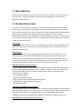
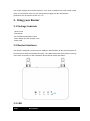
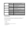
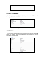
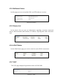
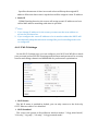
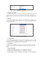
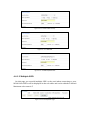
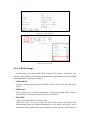
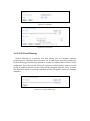
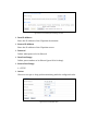
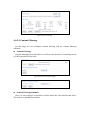
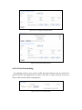
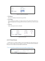
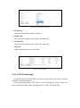
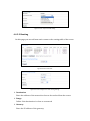
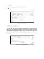
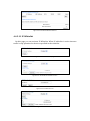
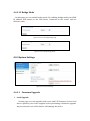
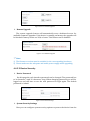
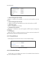
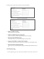
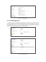
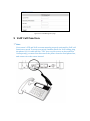
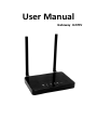
User Manual Gateway U270V Important Notice Due to the nature of wireless communications, transmission and reception of data can never be guaranteed. Data may be delayed, corrupted (i.e., have errors) or be totally lost. Although significant delays or losses of data are rare when wireless devices such as the router are used in a normal manner with a well-constructed network, the router should not be used in situations where failure to transmit or receive data could result indamage of any kind to the user or any other party, including but not limited to personal injury, death or loss of property. Atel accepts no responsibility for damages of any kind resulting from delays or errors in data transmitted or received using the Atel router or for failure of the Atel router to transmit or receive such data. Safety Precautions Do not operate the router: • In areas where blasting is in progress • Where explosive atmospheres may be present • Near medical equipment • Near life support equipment or any equipment that may be susceptible to any form of radio interference. In such areas, the router MUST BE POWERED OFF. The Atel router can transmit signals that could interfere with this equipment. Do not operate the router in any aircraft, whether the aircraft is on the ground or in flight. In aircraft, the router MUST BE POWERED OFF. When operating, the router can transmit signals that could interfere with various onboard systems. Note: Some airlines may permit the use of cellular phones while the aircraft is on the ground and the door is open. The router may be used at this time. The driver or operator of any vehicle should not operate the router while in control of a vehicle. Doing so will detract from the driver or operator’s control and operation of that vehicle. In some states and provinces, operating such communications devices while in control of a vehicle is an offense. Limitation of Liability The information in this manual is subject to change without notice and does not represent a commitment on the part of Atel. ATEL SPECIFICALLY DISCLAIMS LIABILITY FOR ANY AND ALL DIRECT, INDIRECT, SPECIAL, GENERAL, INCIDENTAL, CONSEQUENTIAL, PUNITIVE OR EXEMPLARY DAMAGES INCLUDING, BUT NOT LIMITED TO, LOSS OF PROFITS OR REVENUE OR ANTICIPATED PROFITS OR REVENUE ARISING OUT OF THE USE OR INABILITY TO USE ANYATEL PRODUCT, EVEN IF ATEL HAS BEEN ADVISED OF THE POSSIBILITY OF SUCH DAMAGES OR THEY ARE FORESEEABLE OR FOR CLAIMS BY ANY THIRD PARTY. TABLE OF CONTENTS 1. Introduction ...................................................................................... 5 2. Product Overview ............................................................................ 5 3. Using your Router ............................................................................ 6 3.1 Package Contents ........................................................................................ 6 3.2 Router Interfaces .......................................................................................... 6 3.3 LED .............................................................................................................. 6 3.4 RJ-45 Switch ................................................................................................ 7 3.5 Other Features ............................................................................................. 7 3.6 Setting up your hardware .............................................................................. 8 4. Configuring your Router................................................................ 9 4.1 Login ............................................................................................................ 9 4.2 Dashboard .................................................................................................... 9 4.3 Status ......................................................................................................... 10 4.3.1 WAN Status............................................................................................................ 10 4.3.2 WiFi LAN Status .................................................................................................... 11 4.3.34G Status................................................................................................................. 11 4.3.4Software Status ...................................................................................................... 12 4.3.5 Device List ............................................................................................................. 12 4.3.6UPnP Status ............................................................................................................ 12 4.3.7VoIP......................................................................................................................... 12 4.4 Settings ...................................................................................................... 13 4.4.1 Basic Settings ........................................................................................................ 13 4.4.2Advanced Settings ................................................................................................. 21 4.4.3System Settings ...................................................................................................... 32 4.5 4G ............................................................................................................... 37 4.5.1APN Settings ........................................................................................................... 37 4.5.2 PIN Management................................................................................................... 38 5. VoIP Call Function ......................................................................... 39 5.1 Activating Voice over IP .............................................................................. 40 5.2 Placing Voice Calls ..................................................................................... 40 5.3 Receiving Voice Calls ................................................................................. 40 6. Technical Specification ............................................................... 40 7. Certification .................................................................................... 41 1. Introduction Thank you for purchasing the U270V router with Voice over IP (VoIP). This user manual will help you setup, configure and outline best practices for maximizing your home network performance with the router. 2. Product Overview In minutes, you will be able to connect your computers to the Internet and you will be able to make a phone call using VoIP. The following is a list of features that make your new U270V router an ideal solution for your home or small office network. Implementation of these features depends on the particular service provider and account features you have chosen. Some features described in this manual may not be supported by your service provider or may not be available with your network account. For details of the services and accounts available, contact your service provider. VoIP Calling Your router (U270V) features a Voice over Internet Protocol (VoIP) function that allows you to make voice calls over a VoIP network by simply connecting a wired, landline phone to your network-connected router. Plug-and-Play Your router was factory-set for compatibility with a particular service provider. Thus, your router operates on radio channels and enables services specific to your network service provider. Once your router has been activated on your service provider’s network, you can connect to the Internet. After your router is activated, connect it to your computer using the Ethernet (RJ-45) cable or via Wi-Fi. You are now ready to use the Internet. Web-Based Advanced User Interface You can easily setup the router’s advanced functions through your web browser and without having to install additional software onto your computer. There are no drivers to install and, you can easily make changes and perform setup functions from any computer that is connected to your U270V •NAT IP Address Sharing •Support for VPN Pass Through •Built in Dynamic Host Configuration Protocol (DHCP) •Integrated 802.11b/g/n Wireless Access Point •MAC Address Filtering Integrated 10/100 Mbit/s 3-Port Switch The U270V has a built-in 3-port network switch to allow your wired computers to share printers, data and MP3files, digital photos, and much more. The switch features automatic detection so it will adjust to the speed of connected devices. The switch will transfer data between computers and the Internet simultaneously without interrupting or consuming resources. Integrated 802.11 b/g/n Wireless Access Point The U270V supports Wi-Fi modes b/g and n. Your router as default is set to Wi-Fi b/g/n mixed mode. To use another mode you can change this by logging into the web interface (instructions can be found in section 4.4.1.2). 3. Using your Router 3.1 Package Contents •U270V router •2xAntennas •RJ-45 Ethernet Networking Cable •Power Supply and Car Charger (12V) •Quick guide 3.2 Router Interfaces The U270V is designed to be placed on a desktop or wall mounted. All the ports at the back of the router are for better organization and utility. The LED indicators are easily visible on the top of the router to provide you with information about network activity and status. 3.3 LED Items Description Power WIFI WPS Connect Signal On(Yellow) Only charger plug or Full charged Blinking(Yellow) Charger plug in and charge for battery Blinking (Red) Battery in and no charger plug in the battery is in low status, On(Yellow) WIFI has turned on Blinking(Yellow) Active data passed through Wi-Fi OFF WIFI has turned off Blinking(Yellow) WPS is activated. WPS led is off after one minutes Off WPS is Off On(Yellow) LTE data connection is established Blinking(Yellow) LTE data is connecting Off No data connection On(Yellow) Band 31 On(Green) Band 3 On(pink) Band 7 On(Blue) Band 20 3.4 RJ-45 Switch The RJ-45 Switch has three Ethernet ports supporting up to 100 Mbit/s. Use any of the 3 ports and an Ethernet cable to connect the router to your computer. 3.5 Other Features (1)WPS Key (2)Reset Key (3)Phone line(RJ-11) (4)Network connection to Computers (RJ-45/Ethernet) (5)Power On/Off Switch (6)Power Jack 3.6 Setting up your hardware 1. 2. Make sure your router is not connected to any power source and that all the LEDs are OFF. How to setup the antennas for maximized performance: ①Antennas are located on both sides of the router. ②Attach the antennas to the back of the router ③Hand tighten the antennas so that they are securely attached to the router 3. 4. 5. Locate the power supply that is included with your router. Plug the power supply’s small connector into the power port on the router (6). Plug the power supply into an empty power outlet. Switch on the router (5). Look at the Power LED on top of the router and make sure the LED is lit. Wait for a few seconds while the router searches for network service. When the router finds 6. a suitable network the Connect LED is lit yellow. Refer to the Signal LED’s for acquired signal strength and band. Locate the Ethernet cable that is included with your router. Plug one end of the cable into any Ethernet port on your router. Plug the other end of the cable into the networking port on your computer. Alternatively connect to the router through Wi-Fi 4. Configuring the router The following section will guide you through the steps to properly configure and personalize all settings in your router. 4.1 Login Open a web browser and enter 192.168.0.1 in the address bar. A login window will be displayed and you will be prompted to enter a username and a password to login. Use the following information to login: Username: admin Password: admin When successfully logged in you will be able to navigate through the web interface of the router. The web interface persists of four main section called Dashboard, Status, Settings and 4G. Every section has their own submenus with pages to display more specific information or options for that particular subject or feature. 4.2 Dashboard On the dashboard you will have a view over the most important information the web interface can provide including radio parameters, WAN and LAN IP addresses, Wi-Fi SSID and password, software versions and SIM identification numbers and at the top you can find SIM status, connection status as well as a hyperlink to Net1 support webpage and the logout button. Figure 4-2-1Dashboard Page 4.3 Status In this section you will find the status pages for Wi-Fi & LAN, 4G, Software versions, Device List, UPnP and VoIP. Figure 4-3-1 Status 4.3.1 WAN Status On the WAN Status page you can see WAN IP Address, WAN Primary DNS and WAN Secondary DNS information. Figure4-3-1-1 WAN Status 4.3.2 WiFi & LAN Status On this page you can see Wi-Fi & LAN information such as SSID, Channel, Security mode, LAN IP and DHCP Server information. Figure 4-3-2-1 WiFi LAN Status 4.3.3 4G Status In the 4G Status menu you can see LTE information like Connection Status, SIM Status, SIM numbers, Radio levels, MIMO status and frequency of the LTE network you are connected to. Figure 4-3-3-1 LTE Status 4.3.4 Software Status On this page you can see installed IDU- and LTE software versions. Figure 4-3-4-1 Software 4.3.5 Device List In the device list you can see information regarding currently connected devices like hostname, MAC address, IP address, expiring time and connection type. Figure 4-3-5-1 Device List 4.3.6 UPnP Status On the UPnP Status page you can see rules for active UPnP connections. Figure 4-3-6-1 UPnP 4.3.7 VoIP The VoIP page displays Registration status and VoIP APN. Figure 4-3-7-1 VoIP 4.4 Settings The Settings section consists of three main menus named Basic Settings, Advanced Settings and System Settings. Figure4-4-1 Settings 4.4.1 Basic Settings Figure4-4-1-1 Basic Settings 4.4.1.1 LAN Settings On the LAN Settings page all settings for the internal LAN can be viewed and changed. Figure 4-4-1-1-1 LAN Settings IP Address Enter the IP address of your router (factory default: 192.168.0.1). Subnet Mask Subnet mask is an address code that determines the size of a network. The subnet mask is by default set to 255.255.255.0 (/24) and cannot be changed. DHCP Enables or Disables the DHCP server. If you disable the DHCP server, you must have another DHCP server within your network or you will have to configure static IP addresses on all other devices. Start IP Address Specifies an IP address for the DHCP server to start with when assigning IP addresses to hosts. The default starting address is 192.168.0.2. This address cannot end with .0, .1 or .255 as these addresses are reserved for network, gateway and broadcast addresses. End IP Address Specifies an ending IP address with when assigning IP addresses to hosts. When all IP addresses are used no more devices can be connected. The default end address is 192.168.0.254. This address cannot end with .0, .1 or .255 as these addresses are reserved for network, gateway and broadcast addresses. Lease Time Specifies the amount of time in seconds a host will keep the assigned IP address. When the lease time is up the host will be assigned a new IP address. Static IP IP/MAC binding function, the router will assign a static IP address to a host with a MAC address matching with what is specified. Note: 1. If you change IP address for the router you must use the new address to access the web interface. 2. If you configure the router IP address to be in another subnet the DHCP will automatically adapt but advanced settings like port forwarding needs to be re-configured. 4.4.1.2 Wi-Fi Settings On the Wi-Fi Settings page you can configure your Wi-Fi and WLAN to match your personal preference like changing network name and password for security reasons and change channel and bandwidth for performance optimization. Figure 4-4-1-2-1 WiFi Settings Wi-Fi Status The Wi-Fi status is enabled in default, you can only connect to the device by CAT-5 Ethernet cable if it is disabled. Wi-Fi Standard The router can operate in five different wireless modes: ”11b/g mixed mode”, “11b only”, “11g only”, “11b only”, ”11b/g/n mixed mode”. Figure 4-4-1-2-2 WiFi standard Network Name (SSID) To identify your wireless network, a network name called SSID (Service Set Identifier) is used. You can set it to anything you like and you should make sure that your SSID is unique if there are other wireless networks operating in your area. Channel This option determines what frequency your WLAN will be operating in. It is not necessary to change channel unless you are experiencing interference from other nearby WLANs. Figure 4-4-1-2-3 Frequency (Channel) Broadcast SSID By broadcasting the SSID local wireless devices will display the network name in its list of available WLANs. If broadcasting is disabled the SSID is “invisible” and must be entered manually by the user in the device. AP Isolation This function can isolate wireless stations on your network from each other. Wireless devices will be able to communicate with the router but not with each other. Channel Bandwidth 20 MHz channel bandwidth support up to150 Mbit/s connections. 40 MHz channel bandwidth support up to 300 Mbit/s connections. Security Mode: Disabled, OPENWEP, SHAREDWEP, WPA-PSK, WPA2-PSK, WPA-PSK/WPA2-PSK a) WEP Security Mode Security Mode: OPEN, SHARED Key Format: Hexadecimal and ASCII formats are provided. Hexadecimal format stands for any combination of hexadecimal digits (0-9, a-f, A-F) in the specified length. ASCII format stands for any combination of keyboard characters in the specified length. Default Key: Anyone of Key 1, Key 2, Key 3 and Key4 with 2 kinds of key format. Figure 4-4-1-2-4 OPENWEP Figure 4-4-1-2-5 SHAREDWEP b) WPA Security Mode Security Mode: WPA-PSK, WPA2-PSK, WPA-PSK/WPA2-PSK WPA Algorithms: TKIP, AES, TKIPAES Keywords: 1~32 characters Key Renewal Interval: 0~4194303s Figure 4-4-1-2-6 Default WiFi Security Figure 4-4-1-2-7 WPA-PSK Figure 4-4-1-2-8 WPA-PSK/WPA2-PSK 4.4.1.3 Multiple SSID On this page you can add multiple SSID’s to be used when connecting to your WLAN. New SSID’s will be displayed in the rule table and can be edited or deleted. Maximum rule count is 5. Figure 4-4-1-3-1 Multiple SSID page Figure 3-4-1-3-2 Add New Rule Figure 4-4-1-3-3 Rule Table 4.4.1.4 WPS Settings On this page, you can modify WPS settings. This feature can make your wireless client within a few minutes automatically synchronized with the WLAN and establish the connection via Wi-Fi. WPS method Push the button (default), Enter the PIN of client device, Use the PIN of the device. WPS Status This displays the real-time information of WPS processing while wireless client tries to communicate with each other over Wi-Fi. PBC Mode (1)Press the WPS button on your router. (2)If your device is set to search for other WPS devices the router will automatically send it’s WLAN information to your device over Wi-Fi and a handshake will be performed between them and your device will connect to your WLAN. Enter the PIN of client device (1) Wireless clients choose enrollee mode, the wireless client software will randomly generate a PIN code. Then click on the tool interface "PIN" button. (2) Input the PIN code which got from the wireless client and click the “Apply” button on this “WPS” configuration page. Use the PIN of the device (1)Create the random PIN by clicking the “Generate” button, and share this PIN to wireless client. (2) In the wireless client choice registrar model, and the input device of the PIN code. Figure 4-4-1-4-1 WPS page 4.4.1.5 UPnP On this page you can enable or disable UPnP. Figure 4-4-1-5-1 UPnP 4.4.2 Advanced Settings Figure 4-4-2-1Advanced Settings 4.4.2.1 MAC Filtering MAC filtering is a security tool that allows you to configure internet restrictions for specified devices based on MAC address. MAC filtering is disabled by default so it must be enabled before filters can be configured. If you choose the “Allowed” option for default policy, packets routed to the MAC address specified in the rules will be dropped and vice versa. In short the “Allowed” option is creating a blacklist and the “Dropped” option is creating a whitelist. Figure 4-4-2-1-1 MAC Filtering page Figure4-4-2-1-2 Enable MAC Filtering function Figure4-4-2-1-3 Add Rule Figure4-4-2-1-4 Rule Table 4.4.2.2 IP/Port Filtering IP/Port filtering is a security tool that allows you to configure internet restrictions for specified devices based on IP addresses and port number(s). IP/Port filtering is disabled by default so it must be enabled before filters can be configured. If you choose the “Allowed” option for default policy, packets routed to the IP address specified in the rules will be dropped and vice versa. In short the “Allowed” option is creating a blacklist and the “Dropped” option is creating a whitelist. Figure 4-4-2-2-1 IP/Port filtering page Figure4-4-2-2-2 Enable IP/Port Filtering function Dest IP Address Enter the IP address of the IP packet destination. Source IP Address Enter the IP address of the IP packet source. Protocol Define what protocol to be filtered. Dest Port Range Define port numbers to be filtered (port 80 is for http). Source Port Range 1 - 65535 Action Choose to accept or drop packets matching with the configured rules. Figure 4-4-2-2-3 Add New Rule Figure 4-4-2-2-4 Rule Table 4.4.2.3 Content Filtering On this page you can configure content filtering and the content filtering schedule. Content Filtering Content filtering blocks all traffic to and from web browsers containing words or URL’s specified in the rules. Figure 4-4-2-3-1 Content Filtering page Figure 4-4-2-3-2 Add New Rule Content Filtering Schedule Here you can configure a schedule to define when the rules should take effect. This feature is disabled by default. Figure 4-4-2-3-3 Configure Filtering Schedule Figure 4-4-2-3-4 Content Filtering Rules 4.4.2.4 Port Forwarding By opening ports in your router traffic from the internet can be routed to a specific device and application in your LAN. This is often used by servers or devices that needs remote management Figure 3-4-2-4-1 Port Forwarding page Figure 4-4-2-4-2 Port Forwarding Setting IP Address Enter the IP address of the device in your LAN. Port Range Enter a fixed port number or a range of ports to be opened. This value has to match the application running on the local device (web servers often use port 80). Protocol Define what protocols to be allowed. Figure 4-4-2-4-3 Rule Table 4.4.2.5 Virtual Server Virtual server is a feature similar to port forwarding. You open ports in your router to allow traffic from the internet to enter your LAN with the difference that ports can be different on the WAN and LAN side. Note: Virtual server specifies only one port and not range of ports. Figure 4-4-2-5-1 Virtual Server page Figure 4-4-2-5-2 Virtual Server Setting IP Address Enter the IP address of the local device. Public Port Enter the port number to be used on the WAN side. Private Port Enter the port number to be used on the LAN side. Protocol Define what protocols to be allowed. Figure 4-4-2-5-3 Rule Table 4.4.2.6 VPN Passthrough A virtual private network (VPN) is a point-to-point connection across a private or public network (Internet). VPN Passthrough allows VPN traffic to pass through the router. There are three main kinds of the VPN tunneling protocol, PPTP, L2TP and IPSec. Figure 4-4-2-6-1 VPN Passthrough Note: VPN Passthrough does not mean the router can create VPN endpoints. VPN pass through is a feature that allows VPN traffic created by other endpoints to "pass through" the router. 4.4.2.7 Demilitarized Zone On this page you can configure a De-militarized Zone (DMZ) to separate internal network and Internet. By doing so all traffic destined to your WAN address will automatically be routed to the specified LAN IP address. DMZ IP Address Enter the IP address of the local device. Figure 4-4-2-7-1 DMZ page Figure 4-4-2-7-2 DMZ Setting 4.4.2.8 Dynamic DNS With DDNS you can map your WAN IP address with a DNS provided by any of the DNS providers found in the list. Dynamic DNS is disabled by default. See the chosen provider’s web page for more information. Figure 4-4-2-8-1 Dynamic DNS setting 4.4.2.9 Routing On this page you can add new static routes to the routing table of the router. Figure4-4-2-9-1 Rule Table Figure 4-4-2-9-2 Configure the static routing settings Destination Enter the address of the network or host to be reached from the router. Range Define if the destination is a host or a network. Gateway Enter the IP address of the gateway. Interface Define if the gateway is on the LAN or WAN side. RIP When RIP is enabled the router will learn new routes from nearby devices. Figure 4-4-2-9-3 New rule table 4.4.2.10 Wireless Clients On this page you can see the detailed information about connected wireless devices, such as IP address, MAC address, MCS and RSSI. You can also ban user by selecting them by checking the box under “Select” and then click the “ban” buton, the connection will be disconnected immediately. Banned users will be shown under kicked wireless stations. Banned users can be restored. Figure4-4-2-10-1 Connected Wireless Stations Figure 4-4-2-10-2 Kicked Wireless Stations 4.4.2.11 IP Whitelist On this page you can activate IP Whitelist. When IP whitelist is active internet traffic is only permitted to devices specified in the whitelist. Figure 4-4-2-11-1 IP Whitelist page Figure 4-4-2-11-2Enable IP whitelist function Figure 4-4-2-11-3Add new rule Figure 4-4-2-11-4 Rule Table 4.4.2.12 Bridge Mode On this page you can enable bridge mode. By enabling bridge mode your WAN IP address will passed to the first device connected to the router with an Ethernet cable. Figure 4-4-2-12-1 LTE Bridge Setting page Figure 4-4-2-12-2Enable bridge mode 4.4.3 System Settings Figure 4-4-3-1 System Settings 4.4.3.1 Firmware Upgrade Local Upgrade On this page you can upgrade both router and LTE firmware from a local device. Speak to your router supplier before performing a firmware upgrade. Any inconvenient use of this feature will damage the device. Figure 4-4-3-1-1 Firmware Upgrade Remote Upgrade The remote upgrade feature will automatically scan a dedicated server for available firmware upgrades. If the device is running on battery the upgrade will be blocked if battery levels are 20% or lower. This feature can be disabled. Figure 4-4-3-1-2Remote Upgrade Note: 1) The firmware version must be suitable for the corresponding hardware; 2) Please make sure the adequate and stable power supply while upgrading. 4.4.3.2 Device Security Device Password On this page the web interface password can be changed. The password has to be between 1 and 32 characters long. When changing password you will be logged out and will have to use the new password to login again. The default password is ‘admin’. Figure 4-4-3-2-1 Device Settings System Security Settings Here you can configure system security options to protect the device from the external attacks. Figure 4-4-3-2-2System Security Settings page Remote management(via WAN) Enables or disables the possibility to access the web interface over the internet. Remote management(via Wi-Fi) Enables or disables the possibility to access the web interface over WiFI HTTPS Web Login Enables or disables the use of https. Respond to PING on WAN When this is enabled the router will respond on ICMP requests coming from the internet. SPI Firmware Enable this feature to enhance protection to all the wired and wireless PCs against intruders and most known Internet attacks. 4.4.3.3 Reset& Reboot On this page you can reboot the router or restore default settings. Figure 4-4-3-3-1 Factory Reset 4.4.3.4 Scheduled Reboot On this page you can configure the router to do scheduled reboots based on day of the week and hour of the day. Figure 4-4-3-4-1 Scheduled Reboot 4.4.3.5 NTP On this page you can configure date and time for the router. When connected to the internet the router will automatically sync it’s time settings with specified NTP server. By default it is se.pool.ntp.org. Figure 4-4-3-5-1 NTP Setting 4.4.3.6 Backup & Restore On this page you can back up your custom configurations and store them locally in your device. The configurations-file can be used to restore your personal settings if lost or to add them on another U270V router. Figure 4-4-3-6-1 Backup & Restore 4.4.3.7 Watchdog On this page you can enable the watchdog feature. The watchdog is used to ping a remote device and will reboot if a specified numbers of requests timeouts in order to rule out the router as the root cause of the failure. Figure 4-4-3-7-1 Ping Watchdog page Figure 4-4-3-7-2 Enable Ping Watchdog URL or IP address to ping Define what URL or IP to ping. Number of ICMP Request per ping group Define the number of ICMP requests to be sent for every ping. Wait time of the ICMP Request(s) The default value is 3, you can also change it to other values. Amount of fail ICMP to consider “FAIL” situation Define how many timouts to be allowed per ping before restarting the router. Wait time between ping groups(min): Define the time in minutes between pings, the default and minimum value is 3. 4.4.3.8 System Log In the system log you can read recent activities in the router such as IP changes, reboots and if any firmware upgrades have been made. Figure 4-4-3-8-1 System Log page 4.5 4G The 4G section has two submenus, APN settings and PIN Management. Figure 4-5-1 4G 4.5.1 APN Settings On this page you can configure the router to connect to a custom APN. Faulty configurations will make internet connection unavailable. Please contact customer service for further instructions. Figure 4-5-1-1 LTE APN page 4.5.2 PIN Management On this Page you can enable or disable the use of PIN lock. Your PIN code can be found on the back of the SIM card shipped in the router package and you will be prompted to enter it on boot. Enter the PIN by accessing the web interface page. After 3 failed attempts the device will be locked Figure 4-5-2-1 PIN Management page Figure 4-5-2-2 Enable the PIN Figure 4-5-2-3 PUK Management page 5 VoIP Call Function Note: Your router’s LTE and VoIP accounts must be properly activated for VoIP call functions to work. To setup your wired, landline phone for VoIP calling, plug the phone’s RJ-11 cable into the “TEL” port on your router as shown below. Consequently, you must first disconnect the phone from the fixed phone line, and connect it to the router instead. 5.1 Activating Voice over IP In order to use Voice over IP you must have an account with Net1. If you do not have the service pleasecontact Customer Service. 5.2 Placing Voice Calls 1. Turn on the router. 2. Lift the handset from your phone. 3. When you hear a dial tone, use the phone’s numeric keypad to dial the desired phone number 5.3 Receiving Voice Calls The telephone(s) connected to the router will ring when receiving an incoming call. 1. Lift the telephone’s handset to answer a call. Note: To answer an incoming call while you are holding the receiver, press any key on the phone’s numeric keypad. 6 Technical Specification Size 180(L)*128(W)*23(H) mm Weight 310g Battery Type Li-ion (2 cell), 3.7V(Max 4.2V)/5200mA/h Operating Temperature -20o C ~ +70o C Storage Temperature -30o C ~ +80o C Humidity 5 ~ 95% Stand by Time Up to 7 hours Usage Time Up to 3 hours Adaptor Input AC 100-300V Adaptor Output 12V/1A 7 Certification