1
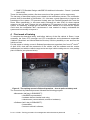
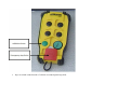
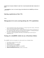
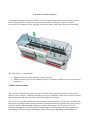
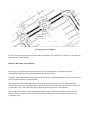
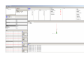
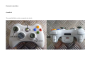
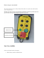
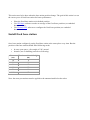
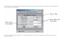
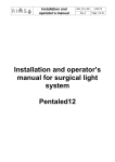
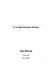
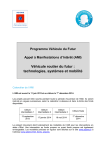
EUROPEAN COMMISSION
DG RESEARCH
SIXTH FRAMEWORK PROGRAMME
THEMATIC PRIORITY 1.6
SUSTAINABLE DEVELOPMENT, GLOBAL CHANGE & ECOSYSTEMS
INTEGRATED PROJECT – CONTRACT N. 031315
Training procedure for management and
maintenance personnel
Deliverable no.
Dissemination level
Work Package
Author(s)
Co-author(s)
Status (F: final, D: draft)
File Name
Project Start Date and
Duration
1.3.1.7
Public
WP 1.3
G. Giustiniani
N.M. Buccino, A. Lago, M. Ghrissi
D_13.10.11
D1.3.1.7-Public-Giustiniani-Draft.doc
01 May 2006 – 31 December 2011
D1.3.1.7-Public- Training procedure for management and maintenance personnel
1
TABLE OF CONTENTS
1 Executive Summary
4 2 Introduction
6 3 Theoretical background and selection of personnel
7 4 First week of training
8 5 Delivery of the vehicle in Rome and second week of training
9 6 On field tests and training
10 7 Conclusion
11 Annex A - Maintenance guide
Annex B - Operation manual
Annex C - Quick start guide
Annex D - Users manual
D1.3.1.7-Public- Training procedure for management and maintenance personnel
2
FIGURES
Figure 1 - Overview of the CTS as it should be implemented.
6
Figure 2 - The training course in Robosoft premises – how to pull out battery rack.
8
Figure 3 - View of the vehicle.
9
Figure 4 – Different moments of training in Rome.
D1.3.1.7-Public- Training procedure for management and maintenance personnel
10
3
1 Executive Summary
This report describes the training activities carried out by ITR in cooperation with Robosoft in
view of the opening to public of Rome demonstration. ITR was the coordinator of Rome
demonstration and was in charge of management and maintenance of the CTS once it would
be opened to public and Robosoft is the CTS provider.
The training process started in 2008 and ended in May 2011 because of the stop of Rome
demonstration. The training process can be divided in two phases. A first part in which ITR
personnel acquired a good knowledge and a deep comprehension of the system and a
second part more oriented to the daily management of the system.
The first step of the training can be considered the Rome demonstration designing phase
where the first basic and theoretical concepts about the systems were acquired by ITR. This
first system knowledge allowed defining which professionals’ figures were needed to manage
and maintain the system. The three figures defined are:
• CTS manager.
• CTS management and maintenance responsible.
• Operator.
Another important activity that provided a good knowledge and deep comprehension of the
system was the direct involvement of the ITR personnel in the certification process.
The first phase of the training mainly aiming to improve the knowledge and comprehension of
the system ended with a training course held by Robosoft to ITR personnel in Robosoft
premises from 19th to 23rd of April 2010. The course provided some base knowledge about:
hardware devices location and using, maintenance procedures and software (access to
vehicle’s software, update software, remote maintenance). After these two days of desk
training there were two full days of on field training with the vehicle mainly on: record a
trajectory, follow a trajectory, understand and fix errors.
With the delivery of the vehicle in Rome (July 2010) in the ATAC Magliana bus depot started
a second phase of the training aiming at train ITR personnel for the day by day system
management and maintenance. The Robosoft personnel come in Rome from 30th of August
to the 3rd of September 2010 for training on very practical activities such as, charging the
vehicle and battery management or put in place and calibration of the GPS base antenna.
Concluded this week of training started an intense period of on field CTS test and on field
training run by ITR personnel with the remote support of Robosoft personnel lasted until May
2011. During this period ITR personnel had the opportunity to further improve its knowledge
of the vehicle and of the daily practical management and maintenance procedures. During
this long testing/training period user’ manuals provided by Robosoft were reviewed and
adapted to the local conditions.
Unfortunately this process of reviewing and improving the manuals was not finished because
the Rome demonstration was closed.
This training, two years in duration, carried out thanks mainly to the cooperation of ITR and
Robosoft showed many interesting aspects. First of all the training is divided in two main
phases and in a first phase the future management and maintenance high profile figures
have to acquire a deep knowledge and, most important, comprehension of the system
weakness, strengths and limits. To achieve this objective it is very important that such
professionals’ figures are involved in the early stage of the system design and in the
certification process.
The second phase of the training addressed the daily management and maintenance of the
system, and nevertheless is important that all the professionals figures are involved, this part
is mostly for those low profile figures (operators) that will carry out the daily operations.
During this second phase is also important to review the different user’s manuals that are
provided by the system provider (in this case Robosoft) to adapt to the local conditions.
D1.3.1.7-Public- Training procedure for management and maintenance personnel
4
Concluding the sharp end of Rome demonstration did not allow to go on with the training. For
this reasons some relevant aspects of training mostly related to the operation of the system
with users on-board are not here reported.
D1.3.1.7-Public- Training procedure for management and maintenance personnel
5
2 Introduction
The objective of the CityMobil project is to contribute to a more effective organisation of
urban transport, resulting in a more rational use of motorised traffic with less congestion and
pollution, safer driving, a higher quality of living and an enhanced integration with spatial
development. In order to achieve these objectives advanced concepts for advanced road
vehicles and passengers are developed. Furthermore new tools for managing the urban
transport are introduced and barriers that are in the way of large-scale introduction of
automated systems are removed.
In the first sub-project of CityMobil (SP1) those advanced concepts and tools are validated
and demonstrated in a number of different European cities under different circumstances.
Therefore three large-scale demonstrators have been chosen and transport innovative
systems should be implemented in the city of Heathrow, Rome and Castellón. The three
cities were selected in the preparation phase of the project based on the assessment of
technical feasibility, political support in form of Letters of Intent, a commitment to invest
financially in the project and an availability of a local consortium consisting of public and
private organizations, which had expressed commitment to the plans.
The Rome demonstration had to implement a Cybernetic Transport System (CTS) in the New
Rome Exhibition parking place and to open it to public permanently. A CTS is a system where
vehicles without drivers (Cybercars) operate an on demand transport service in a mixed
environment at least with pedestrians and cyclists.
The system designed has a track round trip length of about 1.6 km and 11 stops as reported
in Figure 1.
Figure 1 - Overview of the CTS as it should be implemented.
The main aim of this report is to describe the training activities carried out by ITR in
cooperation with Robosoft in view of the opening to public of Rome demonstration. ITR was
the coordinator of Rome demonstration and was in charge of management and maintenance
of the CTS once opened to public and Robosoft is the CTS provider.
The training process can be divided in two phases. A first parts in which ITR personnel has
acquired a good knowledge and a deep comprehension of the system and a second part
more oriented to the daily management of the system.
The first part started from the Rome demonstration designing coordinated by ITR and
finalized in July 2009, because during this activity ITR personnel acquire a first good
knowledge of the system and of its components. Another very important preliminary training
D1.3.1.7-Public- Training procedure for management and maintenance personnel
6
activity was the Rome demonstration certification process coordinated by ITR. The first
phase of training ended with a theoretical and practical course attended by the ITR personnel
in Robosoft premises. This first phase is described in chapters 3 and 4.
The second part started with the delivery of the vehicle in Rome in July 2010 in the ATAC bus
depot made available also for vehicle testing. In late August 2010 Robosoft personnel came
in Rome for one week to train ITR personnel on the daily management and maintenance and
than from September 2010 on ITR personnel run and maintain the vehicle in ATAC bus depot
with the remote support of Robosoft. This phase is described in chapters 5 and 6.
In chapter 7 the conclusions are reported.
3 Theoretical background and selection of personnel
The first step of the training process start from the final designing of the system indeed ITR
contributed and coordinated the preparation and finalization of the “Rome demonstration
detailed design” (D.1.3.2.2). This first work gave the opportunity to understand the system its
needs, strengths and problems on vehicle side, station side and track and civil works side.
This activity started in late 2008 ended in July 2009.
According to knowledge coming from the system design phase was possible to define a list
of professional figures needed to manage the system once opened to public. Taking in
consideration the specific local conditions and small dimension of the system a first
assessment allowed indentifying three different professionals’ figures:
• CTS manager. This professional figure is in charge of all the aspects related to the CTS
management and the maintenance and is also in charge to keep the contacts with
external stakeholders such as Rome Municipality, ATAC, Ministry of Transport (MoT)
for certification process, Fiera di Roma and with Robosoft the CTS provider. For this
professional figure an Engineer was considered needed;
• CTS management and maintenance responsible: this professional figure is in charge of
all the technical and operational aspects related to the CTS management and
maintenance. He has to verify that that system is operated according to the
guidelines and the maintenance operations are run in the correct way. For major
ordinary maintenance operations, such as the changing of a wheel, he has to be
there and to guide the operations. He is in charge to keep the contacts with the
system provider (Robosoft) for technical and operational aspects such
definition/modification of safety, operational and maintenance procedures. For this
professional figure an electronic Engineer with some background in programming
was needed.
• Operator. The Operator will carry out the day by day CTS operations such as: start the
system in morning and operate it during the day following the operation from the
control room, support the users in case of CTS malfunction according to the
procedures defined, carry out ordinary maintenance operations and close the system
and the end of the day. In a first stage it was planned to have two operators in each
shift and a reduction to one operator for shift would be evaluated after the opening of
the system according also to the indication of MoT. The operator has to have a
technical background.
Defined which kind of professionals figures were needed to manage the Rome
demonstration the selection of the CTS management and maintenance responsible was
carried out and he started theoretical study of documents available that were:
1. Rome demonstration detailed design (available since 2009);
2. Safety Assessment of the Cybernetic Transport System for the Fiera di Roma
(available since 2009);
3. RobuRIDE Safety Testing (available since 2010);
D1.3.1.7-Public- Training procedure for management and maintenance personnel
7
4. ROME CTS Detailed Design robuRIDE 25 Additional information - Round 1 (available
since 2010).
These four documents provide a first clear overview of the system in all its components.
The last step of theoretical training was related to the certification process. The certification
process itself is described in Deliverable 1.3.1.4 but was a good opportunity to improve the
knowledge of the system. ITR personnel indeed were the interface between MoT and the
Rome Demo partnership, in this case mainly Robosoft but also ATAC for those aspects
related to the civil work. Playing this role allowed to ITR personnel to fully understand the
system, its weakness, strength and its technical limits. Indeed to be sure that the system
could meet the certification MoT requirements it was needed to deeply understand the
system and how modify or improve it.
4 First week of training
To complete the theoretical study, and before delivery of the first vehicle in Rome, it was
necessary the future CTS manager and CTS management and maintenance responsible
(Gabriele Giustiniani and Nicola Maurizio Buccino) had the possibility to see and test the
vehicle on field.
For this reason a training course in Robosoft premises was organized from from 19th the 23rd
of April 2010, deal with the mecatronic of the vehicle, with the software and the remote
maintenance and with the vehicle usage and a two days vehicle testing was run on a parking
place in Biarritz (see pictures below).
Figure 2 - The training course in Robosoft premises – how to pull out battery rack.
The course held by Robosoft personnel followed the following program:
• Mecatronic (half day in ROBOSOFT):
o robuRIDEs’s presentation,
o hardware devices location and using,
o maintenance (remove wheels, access to hardware).
• Software (half a day in ROBOSOFT):
o presentation,
o access to vehicle’s software,
D1.3.1.7-Public- Training procedure for management and maintenance personnel
8
o update software,
o remote maintenance.
• Vehicle usage (two days in Biarritz):
o install and configure fixed antenna of DGPS,
o record a trajectory,
o follow a trajectory,
o understand and fix errors.
The ITR personnel assisted also to the operation for loading the vehicle on a truck and to the
transport of a robuRIDE from Bidart to Biarritz.
Figure 3 - View of the vehicle.
5 Delivery of the vehicle in Rome and second week of training
After the training in Biarritz held in April ITR personnel had the base knowledge to start
managing the system in Rome with the remote support of Robosoft personnel. In July 2010
the first vehicle was delivered in Rome and hosted in ATAC bus depot located in Rome
outskirt (Magliana). Since the civil works were not ready ATAC made available a temporary
track for testing the vehicle from Monday to Friday from 08:00 a.m. to 01:00 p.m.
From 30th of August 2010 to the 3rd of September Robosoft personnel (Meftah Ghrissi and
Arnaud Lago) moved to Rome for field training. The training was attended by future CTS
manager and CTS management and maintenance responsible (Gabriele Giustiniani and
Nicola Maurizio Buccino) and an operator (Chiara Fazi). The main aim of this week of training
was to acquire a very practical knowledge of all the management and maintenance aspects
of the system such as:
• Charging the vehicle and battery management;
• Put in place and calibration of the GPS base antenna;
• Record and fine tuning of trajectory;
• Manage the vehicle during the testing phase;
• Daily management and maintenance procedures.
D1.3.1.7-Public- Training procedure for management and maintenance personnel
9
Figure 4 – Different moments of training in Rome.
This first week of training give to the ITR personnel the basic knowledge to start using the
vehicle on its own with the remote support of Robosoft personnel.
6 On field tests and training
From 15th of September the ITR personnel start testing the vehicle 5 days a week from 09:00
a.m. to 01:00 p.m.. The test were run until May 2011 (and the data collected from September
2010 to December 2010 are reported in D.1.3.1.6) and during this period ITR personnel had
the opportunity to further improve its knowledge of the vehicles and of the daily practical
management and maintenance procedures. During this long testing/training period Robosoft
delivered the following manuals:
• Maintenance guide;
• Operation manual;
• Quick start guide;
• Users manual.
D1.3.1.7-Public- Training procedure for management and maintenance personnel
10
Also during this period, Robosoft improved the remote monitoring capability of the vehicle,
software update and data log analysis through internet connexion from Biarritz.
According to the experience the ITR personnel were acquiring during the testing some minor
modifications were agreed with Robosoft personnel to improve the manuals and to make
them better meet the local conditions.
Unfortunately this process of reviewing and improving the manuals was not finished because
the Rome demonstration was closed.
7 Conclusion
This report highlights and shortly describes all the steps carried out during the Rome
demonstration to train the ITR personnel to manage and maintain a CTS permanently open
to public.
It is possible to say that this process started from the design phase where the first basic and
theoretical concepts about the systems where acquired. This first system knowledge allowed
to define which professionals’ figures were needed to manage and maintain the system. The
three figures defined are:
• CTS manager. This professional figure is in charge of all the aspects related to the
management and the maintenance of the CTS and is also in charge to keep the
contacts with external stakeholders. For this professional figure an Engineer was
considered needed;
• CTS management and maintenance responsible: this professional figure is in charge of
all the technical and operation aspects related to the CTS management and
maintenance. For this professional figure an electronic Engineer with some
background in programming was needed.
• Operator. The Operator will carry out the day by day CTS operations. In a first stage it
was planned to have two operators in each shift and a reduction to one operator for
shift would be evaluated after the opening of the system according also to the
indication of MoT. The operator has to have a technical and programming
background.
Another important activity that provided a good knowledge and deep comprehension of the
system was the direct involvement of the ITR personnel in the certification process. ITR
personnel were the interface between MoT and the Rome Demo partnership, in this case
mainly Robosoft but also ATAC for those aspects related to the civil work. Playing this role
allowed to ITR personnel to fully understand the system, its weakness, strength and its
technical limits. Indeed to be sure that the system could meet the certification MoT
requirements it was needed to deeply understand the system and how modify or improve it.
The first phase of the training mainly aiming at improve the knowledge and comprehension of
the system ended with a training course held by Robosoft to ITR personnel in Robosoft
premises from 19th to 23rd of April 2010. The course provided some base knowledge about:
hardware devices location and using, maintenance procedures and software (access to
vehicle’s software, update software, remote maintenance). After these 2 days of desk training
there were two full days of on field training with the vehicle mainly on: record a trajectory,
follow a trajectory, understand and fix errors.
With the delivery of the vehicle in Rome (July 2010) in the ATAC Magliana depot started a
second phase of the training aiming at train ITR personnel for the day by day management
and maintenance of the system. The Robosoft personnel come in Rome from 30th of August
2010 to the 3rd for training on very practical activities such as:
• Charging the vehicle and battery management;
• Put in place and calibration of the GPS base antenna;
• Record and fine tuning of trajectory;
D1.3.1.7-Public- Training procedure for management and maintenance personnel
11
• How to mange the vehicle during the testing phase;
• Daily management and maintenance procedures.
This week of training was also attended by a future CTS operator.
Concluded this last week of training started an intense period of on field CTS test and onfield training run by ITR personnel with the remote support of Robosoft personnel lasted until
May 2011. During this period ITR personnel had the opportunity to further improve its
knowledge of the vehicles and of the daily practical management and maintenance
procedures. During this long testing/training period Robosoft delivered the following manuals:
• Maintenance guide;
• Operation manual;
• Quick start guide;
• Users manual.
According to the experience the ITR personnel were acquiring during the testing some minor
modifications were agreed with Robosoft personnel to improve the manuals and to make
them better meet the local conditions.
Unfortunately this process of reviewing and improving the manuals was not finished because
the Rome demonstration was closed.
This nearly two years long training experience carried out thanks mainly to the cooperation of
ITR and Robosoft showed many interesting aspects. First of all the training is divided in two
main phases. In a first phase the future management and maintenance high profile figures
have to acquire a deep knowledge and, most important, comprehension of the system
weakness, strengths and limits. To achieve this objective it is very important that such
professionals’ figures are involved in the early stage of the system design and in the
certification process. Indeed the involvement in the designing phase provide an overview of
the system (provide them with a CTS map) instead the involvement in the certification
process provide a clear comprehension of the system and about the links between its several
components.
The second phase of the training addresses the daily management and maintenance of the
system, and nevertheless is important that all the professionals figures are involved, this part
is mostly for those low profile figures (operators) that will carry out the daily operations. For
this reason it has to be carried out mostly on field with the system running. During this
second phase is also important to review the different user’s manuals that are provided by
system provider (in this case Robosoft) to adapt to the local conditions such as:
• Specific MoT requirements that can easily change from a European country to another.
It is important to say that a small difference in term of laws or requirements could lead
to a relevant change in the design, implementation, management and maintenance of
such systems.
• Specific local conditions such as weather or type of use of the systems;
• Track layout that can deeply change many requirements.
Concluding the sharp end of Rome demonstration did not allow to go on with the training. For
this reasons some relevant aspects of training mostly related to the operations of the system
with users on-board are not here reported.
D1.3.1.7-Public- Training procedure for management and maintenance personnel
12
Annex A - Maintenance guide
D1.3.1.7-Public- Training procedure for management and maintenance personnel
13
Maintenance Guide
From $1
Table of contents
1.
1.
1. 1.1.1.
2. 1.2. Safety considerations
3. 1.3. Preventive maintenance operations and frequency:
4. 1.4. Corrective Maintenance Operations:
2. 2. Details of operations
1. 2.1. Legend
2. 2.2.
3. 2.3. Prevention maintenance operations
1. 2.3.1. Operation P1 : Clean the robuRIDE
2. 2.3.2. Operation P2 : Clean the lights
3. 2.3.3. Operation P3 : Clean the windows
4. 2.3.4. Operation P5 : Verify that there are no mud or objet on the laser
5. 2.3.5. 3.2.4 Operation P6 : Charge the batteries
6. 2.3.6. Operation P7 : Charge the remote mergency stop controller and gamepad
7. 2.3.7. Operation P8 : Control the tires wear.
8. 2.3.8. Operation P9 : Control the clamping of the wheel screw
9. 2.3.9. Operation P10 : Control the aspect of the rims
10. 2.3.10. Operation P11 : Control the correct functionning of the safety equipments.
4. 2.4. Corrective Maintenance action
1. 2.4.1. Operation C1 : Replace a front driving wheel
2. 2.4.2. Operation C2 : Replace a free wheel or driving wheel in the rear
3. 2.4.3. Operation C3 : Replace the safety bumper (in front or rear).
4. 2.4.4. Operation C4 : Replace an engine
5. 2.4.5. Operation C5 : Disconnect the battery power
1. 2.4.5.1. To reconnect the battery power: follow the same procedure backwards
6. 2.4.6. Operation C6 : Replace an internal component
7. 2.4.7. Operation C7 : Replace the pc
5. 2.5. Operations required for long time inactivity preparation (more than 2 months)
1. 2.5.1. Operation D1 : Place vehicle on supports.
2. 2.5.2. Operation D2 : Remove dust in the rear racks.
3. 2.5.3. Opération D3 : Batteries.
6. 2.6. Remote Maintenance
1. 2.6.1. WindowsXPe restore / upgrade procedure
2. 2.6.2. Access to the embeded camera image from Lokarria
This section presents the maintenance operations:
•
•
•
Preventive maintenance: actions allowing to maintain the vehicle on operating conditions.
Corrective maintenance: repairs of the vehicle, consequence of failures.
Remote maintenance: operated by Robosoft employees from Robosoft facilities, to monitor
and update softwares remotely.
Safety considerations
•
Once these maintenance operations are performed, the operator MUST ensure that all
operation conditions are met.
•
For all safety-related maintenance activities, check-lists should be designed by the site
supervisor and completed and signed by the operator performing the maintenance. These
check-lists must be kept for inspection and maintenance plan verification.
•
When any maintenance operation is conducted on a safety-related device, testing of these
functions MUST be conducted.
Preventive maintenance operations and frequency:
The preventive maintenance operations are listed below:
Number Operation
Frequency
Once
Before
each Monthly Annualy
use
Body structure and mechanics
1.
Clean the robuRIDE
2.
Clean the lights
3.
Clean the laser window
4.
Cleand the protective covers of the vehicle rear rack.
5.
Verify that there are no mud or objet on the laser
X
X
X
X
X
Batteries
6.
Charge the batteries
X
7.
Charge the remote emergency stop controller and the gamepad
X
Wheels
8.
Contol tires wear
X
9.
X
10.
Control the clamping of the wheel screws
Control the aspect of the rims (no cracks, no oblong holes at the wheels
screws)
Security tests
11.
Control the correct functionning of the safety equipments.
X
X
X
Corrective Maintenance Operations:
In the next table:
•
•
C indicates an operation taken by qualified operators of the final client, under the
responsibility of the CTS Supervisor
R indicates an operation taken by Robosoft or by the CTS installer if he received an
authorization from Robosoft.
Once one of these corrective operations has been conducted, it is mandatory to conduct all
preventive maintenance operations to ensure operation conditions are met.
In case of doubt, do not hesitate to contact Robosoft: [email protected]
Number
Operation
Autorisation
1.
Replace a wheel
CR
2.
Replace a tire
R
3.
Replace a safety bumper
CR
4.
Replace a motor
R
5.
Disconnect battery power
CR
6.
Replace a battery
R
7.
Replace an internal component
R
8.
Replace the PC
CR
9.
Replace antennas
CR
If a corrective action does not appear in this list, contact ROBOSOFT to get orders.
Details of operations
Legend
Time required for operation
min
h
v
In minutes.
In hours.
Variable.
Difficulty level
Easy, no particular attention required.
Medium, some precautions must be taken.
Difficult, pay great attention to this operation.
Number of people required
1 person.
2 persons.
List of tools required for the operation
Prevention maintenance operations
Operation P1 : Clean the robuRIDE
15min
Stop the robot before proceeding with cleaning: turn off the vehicle general power cut switch to
ensure the vehicle is not powered.
1. Clean the vehicle with products (non corrosive products: alchool...) and rag. No cleaning
with water jet or pressured water allowed.
2. Dry using a rag.
Do not use any scraper or corrosive product in order to prevent damaging of the surfaces.
Operation P2 : Clean the lights
5min
Stop the robot before proceeding with cleaning: turn off the vehicle general power cut switch to
ensure the vehicle is not powered.
1. Clean the front and rear outside lights with a wet sponge and water with non corrosive
clenaning product.
2. Rince with water and sponge.
3. Dry with a rag.
Do not use any scraper or corrosive product in order to prevent damaging of the surfaces.
Operation P3 : Clean the windows
30min
Stop the robot before proceeding with cleaning: turn off the vehicle general power cut switch to
ensure the vehicle is not powered.
1. Clean the windows with a wet sponge and water with non corrosive clenaning product.
2. Rince with water and sponge.
3. Dry with a rag.
Do not use any scraper or corrosive product in order to prevent damaging of the surfaces.
Operation P5 : Verify that there are no mud or objet on the laser
5 min
Perform a visual check and remove any object, mud or dust beeing on the laser windows.
If required, clean the laser window with a wet sponge and water with non corrosive clenaning
product.
3.2.4 Operation P6 : Charge the batteries
5 min
Do not wait for the batteries to be fully discharged before charging them.
1.
2.
3.
4.
Turn off the general power switch to ensure the robuRIDE is poserd down.
Open the vehicle side cover
Plug the 220V cable on the vehicle.
When the battery panel (located on the Operator panel inside the vehicle) indicates a current
value between -7 and -10 Amp, the batteries are beeing charged. The time required for
charging changes based on the battery level.
5. The charge leve is indicated in % on the battery panel.
6. When the vehicle charge is 100%, unplug the cable, close the vhicle side cover and store the
cable in the depot.
For any operation of maintenance, storage or shipping of the batteries, contact Robosoft
Operation P7 : Charge the remote mergency stop controller and gamepad
2min
Do not wait for the batteries to be fully discharged before charging them.
Do not use the remote emergency stop when it is charging.
1. Push the red button on the remote mergency stop controller.
2. Place the controller on the charger.
3. For the remote emergency stop controller, during charging, the red light is continuously on.
The green light gives indication of % charge:
1. Green light blinking : fast charging.
2. Green light on : slow or maintained charging (charge >= 60%).
During remote emergency stop use, a "low battery level" (charge <10%) is indicated by a rapid
blinking of the red light. This indication allows to inform the operator that soon the controller will
not be available, causing a stop of the vehicle. (less than 15min).
For the gamepad, replace the depleted batteries.
Operation P8 : Control the tires wear.
10min
Perform a visual check, using the wear indicators placed inside the groove of the tires.
In case of abdnormal wear, perform a visual chack to identify its origin.
Operation P9 : Control the clamping of the wheel screw
30min
Dynamometrical key with
hexagonal end of size 4
Control the clamping torque with the dynanometrical key. It has to be 10Nm.
Operation P10 : Control the aspect of the rims
30min
The rims are made of aluminum. Control the abscence of cracks or deep impacts or oblong holes at
the screw mounting location. If the rim is cracked, change the wheel.
Operation P11 : Control the correct functionning of the safety equipments.
30min
1.Startup the vehicle
2. Use the gamepad to move the vehicle
3. Press a safety equipment:
a.
Bumpers (front or rear)
b.
Emergency button on the Operator panel.
c.
Emergency button on the remote emergency controller.
4. Safety relay must be disabled and the vehicle must come to a stop.
5. Repeat the opeation for each safety equipments.
Corrective Maintenance action
Operation C1 : Replace a front driving wheel
30min
Hexagonal key, size 4.
1 cric, dedicated supports and forklift
The wheel is mounted with 6 high resistance screws and anti-loosening washers.
1.Lift the vehicle with the the cric and secure it on the dedicated supports.
2. Place the forklift and the dedicated support
3. Uscrew the 6 screws situated inside the cabin
4. Remove the block of motor-wheel
5. Unscrew the 8 screws of the wheel to replace
6. Place the new wheel
7. Clamp the 8 screws at 10Nm on the new wheel (don't forget the washers!).
8. Clamp the 6 screws to fix again the block
9. Put back the vehicle on the ground.
Operation C2 : Replace a free wheel or driving wheel in the rear
30min
Hexagonal key, size 4.
1 cric, dedicated supports and forklift
In the rear, there is a set of 2 wheels on each side. On each set, the external wheel is a free one and
the internal wheel is driving one.
1.Lift the vehicle with the the cric and secure it on the dedicated supports.
2. Place the forklift and the dedicated support
3. Uscrew the 6 screws situated inside the cabin
4. Remove the block of motor-wheel
5. If need to replace the free wheel Unscrew the 8 screws of the wheel and replace it
If need to replace the driving wheel, remove first the free wheel and then unscrew the driving
one and replace it.
6. Clamp the screws at 10Nm on the new wheel (don't forget the washers!).
7. Clamp the 6 screws to fix again the block
8. Put back the vehicle on the ground.
Operation C3 : Replace the safety bumper (in front or rear).
30min
flat and hexagonal keys
1.Stop the vehicle.
2.Push the emergency stop button.
3.Fix the bumper in uprise position using adequate support.
4.Disconnect the bumper (add picture).
5.Remove the mounting srcews of the bumper, placed on the front cover
6.Remove the bumper.
7.Replace with the new bumper by screwing it on the front cover.
8. Reconnect the bumper.
9.Place the bumper in horizontal position.
10. Test the bumper
Operation C4 : Replace an engine
4h
Operation C5 : Disconnect the battery power
15min
Hexagonal keys
This operation MUST be executed BEFORE any operation on the battery packs.
1. Lift the vehicle left covers and secure them.
2. Cut the main power switches by pushing the reote emergency stop and the black push button
on the outside of the vehicle rear racks.
3.Starting from the front of the vehicle, disconnect the first battery rack.
4.Disconnect the second battery rack.
5.Disconnect the third battery rack.
6.Disconnect the 17 pts Jaeger connector.
To reconnect the battery power: follow the same procedure backwards
Operation C6 : Replace an internal component
30min
Attention, this operation could be executed by the custoer but only with the formal
agreement and phone assistance of Robosoft during the operation.
Respect carefully the orders received form the Robosoft technician.
Operation C7 : Replace the pc
30min
Attention, this operation could be executed by the custoer but only with the formal
agreement and phone assistance of Robosoft during the operation.
Respect carefully the orders received form the Robosoft technician.
Operations required for long time inactivity preparation
(more than 2 months)
Operation D1 : Place vehicle on supports.
30min
2 crics and 4 dedicate supports
Place the 2 crics on the same side of the vehicle (one at the front, the other at the rear).
Simultaneously lift the front an rear of the vehicles.
Place 2 dedicated supports as close to the battery packs as possible.
Execute the same operation for the other side of the vehicle.
Operation D2 : Remove dust in the rear racks.
10min
Vaccum cleaner, flat keys
Stop the vehicles, hit the remote emergency stop and the black push button on the vehicle rear rack.
Open the vehicle rear racks, clean the transparent protections and remove them.
Use pressured air.
Close the racks
Opération D3 : Batteries.
10min
hexagonal keys
Fully charge the batteries (100%)
Disconnect the battery power (operation C5)
Remote Maintenance
This part allows you to restore the ARK default image in case of failure and to acces to the camera
image througth Lokarria.
All other remote maintenance action are specific to ROBOSOFT.
WindowsXPe restore / upgrade procedure
This page is restricted.
Access to the embeded camera image from Lokarria
Lokarria is a network robosoft application that connect to robot and display some status and allows
some interactions.
Open a web browser and write in address bar: http://85.31.147.133
user: CityMobilRome
pwd: CityM0bilR0me (o are replaced by zero).
Annex B - Operation manual
D1.3.1.7-Public- Training procedure for management and maintenance personnel
14
Operation Manual
From $1
Table of contents
1.
2.
1.
2.
3.
4.
5.
6.
7.
1. Introduction
2. Conditions allowing operation of the system:
2.1. Before operation of the system:
2.2. During operation of the system:
3. Safety rules:
4. Rules of use:
5. Starting Exploitation of the CTS:
6. Management of events occuring during the CTS exploitation:
7. Towing of a robuRIDE vehicle in case of hardware failure:
1.
2.
1.
2.
3.
4.
5.
6.
7.
1. Introduction
2. Conditions allowing operation of the system:
2.1. Before operation of the system:
2.2. During operation of the system:
3. Safety rules:
4. Rules of use:
5. Starting Exploitation of the CTS:
6. Management of events occuring during the CTS exploitation:
7. Towing of a robuRIDE vehicle in case of hardware failure:
Introduction
The goal of this document is to give the exploitation team all information needed to operate the
CTS (Cybernetic Transport System) in good conditions.
The CTS description, definitions and terminology used in this Operation Manual is described here:
CTS Definitions and terminology
Conditions allowing operation of the system:
It is clearly specified that the vehicles are not designed to transport low mobility persons using
wheelchairs.
The CTS system MUST not be operated in case of snow or ice on the track, and in case of obstacles
or cracks on the track.
Logbooks of all events occuring on the CTS system shoud be implemented by the site supervisor
and signed by the operator acknolewdging the event and detailing the taken actions.
Before operation of the system:
•
•
A complete visual check of the site MUST be carried out to detect and remove obstacles and
exessive tree leaves on the track.
Fleet management system must be started (See: CTS Procedure: starting the Fleet
management system)
During operation of the system:
•
•
•
•
•
•
The Supervisor MUST be continuously monitoring the CTS through the fleet management
system, following CTS Procedure: Monitoring the CTS
No-body is allowed on the track during vehicle operation. If it is required to enter the track
area, the CTS system MUST be stopped using the Fleet Management System.
In case of strong rain or storms, the CTS system should be stopped and vehicles taken back
to the vehicles depot.
Using the CTS vehicles to transport heavy goods is forbidden.
Using the CTS to tract a trailer is forbidden
Smoking inside the vehicles is fobidden.
Safety rules:
Read this manual before using the CTS.
Respect the instructions given in this manual.
When the vehicles are driven manually, the operator MUST continuously keep visibility and
control of the motion he is performing.
When the vehicles are driven manually, the operator MUST continuously keep the remote
emergency stop with him.
In case any abnormal behavior of the vehicle is detected, immediately stop the vehicle using the
Emergency stop button, either on remote emergency stop controller or on the vehicle Operator
panel.
Rules of use:
In order to stop the vehicle in case of problem, it is equipped with 3 systems:
1. A remote mergency stop. It has to be fully charged. It is used to re-arm the power of the
vehicle.
2. An emergency stop, located on the vehicle Operator Panel.
3. A global battery power cut switch.
In order for the vehicles to be operated, all 3 systems MUST be activated.
To power off the vehicle, disactivate the 3 elements in the following order:
1. Push the red button on the remote emergency stop,
2. Push the Emergency stop button on the Operator panel,
3. Turn the global battery power switch to OFF.
NEVER WAIT FOR BATTERIES TO BE FULLY DISCHARGED BEFORE CHARGING T
HEM.
Check the tires pressure every week. The service pressure is 7 bars.
It is forbidden to run over obstacles bigger than defined in the robuRIDE specifications
(apriori 2cm).
Starting Exploitation of the CTS:
•
•
Fleet management system must have been started (See: CTS Procedure: starting the Fleet
management system)
The Supervisor MUST be continuously monitoring the CTS through the fleet management
system, following CTS Procedure: Monitoring the CTS
•
•
•
Start and control the first vehicle by the operator. (See: CTS Procedure: Starting the
vehicles). During this procedure, each vehicle is manually driven to the Virtual Gate,
inserted into the fleet management system and automatically driven to the first station.
When the vehicle reached the first station, Operator can start the second vehicle.
Continue procedure to insert all vehicles.
Management of events occuring during the CTS exploitation:
•
•
•
In case of Emergency Stop (due to passengers or security loop in the vehicle), a full restart
of the vehicle by an autorized staff is mandatory (See CTS Procedure: Starting the vehicles).
In case of any intempestive stop of a vehicle (obstacle detected, trajectory following error
etc), a full restart of the vehicle by an autorized staff is mandatory (See CTS Procedure:
Starting the vehicles), requiring usually that the vehicle is manually driven back to the
maintenance area.
To stop the vehicles, in particular when they are automatically sent to the depot or
maintenance area, follow CTS Procedure: Stopping the vehicles
Towing of a robuRIDE vehicle in case of hardware failure:
The robuRIDE vehicles are designed to be easily towed in case of hardare failure:
•
•
•
•
•
•
•
•
Get a truck or tractor to tow the vehicle
Power off the vehicle
Mount the Drawbar of the robuRIDE.
Lock the drawbar on the robuRIDE
Power on the main power switch of the robuRIDE
Open the robuRIDE left rear rack.
Switch On the Manual break switch.
Drive with lots of caution the robuRIDE to the maintenance area.
Annex C - Quick start guide
D1.3.1.7-Public- Training procedure for management and maintenance personnel
15
Quick Start Guide
From $1
Table of contents
1.
2.
1.
1.
2.
3.
2.
1.
2.
3.
3.
1. Starting robuRIDE
2. Driving robuRIDE
2.1. Moving forward
2.1.1. Turn:
2.1.2. Acceleration:
2.1.3. Deceleration:
2.2. Moving backward
2.2.1. Turn:
2.2.2. Acceleration:
2.2.3. Deceleration:
3. Stoping robuRIDE
This guide will help you to start driving robuRIDE using gamePAD controller.
to do this, you need:
•
•
the robuRIDE.
the gamePAD of the robuRIDE.
•
the remote emergency stop command.
•
keys to switch control mode of vehicle on control panel (top left).
Starting robuRIDE
On the rear left panel (under bumper):
1. Pull the battery controller validation buton.
2. Turn from left to right the power buton.
3. Check all emergency stop buton are released (on control panel and on remote emergency stop).
4. Double click quickly on validation buton (left green) of remote emergency stop command.
5. Turn on gamePAD.
Now you are able to drive robuRIDE. If not, press and realese red button of remote emergency stop command and go to point 4.
Driving robuRIDE
Once the robuRIDE started you are able to drive the robuRIDE.
Check on the panel inside vehicle that the control mode is "manual".
Moving forward
The button A (green) of gamePAD must be kept pressed. If released, the robuRIDE stops.
Turn:
Use left joystick to make the front axle turn.
Acceleration:
Press RT button to request an acceleration ramp, once released, the speed of vehicle doesn't change.
Deceleration:
Press LT button to request a deceleration ramp. once released, the speed of the vehicle doesn't change.
Moving backward
The button B (red) of gamePAD must be kept pressed. If released, the robuRIDE stops.
Turn:
Use left joystick to make the front axle turn.
Acceleration:
Press RT button to request an acceleration ramp, once released, the speed of vehicle doesn't change.
Deceleration:
Press LT button to request a deceleration ramp. once released, the speed of the vehicle doesn't change.
Stoping robuRIDE
1.
2.
3.
4.
Stop the vehicle.
Press emergency stop of remote emergency stop command.
Push the validation battery button on vehicle.
Turn from right to left the power button on vehicle.
Annex D - Users manual
D1.3.1.7-Public- Training procedure for management and maintenance personnel
16
User's Manual
From $1
Table of contents
1. 1. Introduction
2. 2. Conditions allowing operation of the system
1. 2.1. Before operation of the system
2. 2.2. During operation of the system
3. 3. Safety rules
4. 4. Rules of use
5. 5. Starting exploitation of the CTS
6. 6. Management of events occuring during the CTS exploitation
7. 7. Towing of a robuRIDE vehicle in case of hardware failure
8. 8. Vehicle Description
1. 8.1. Overview
2. 8.2. Vehicle control system
1. 8.2.1. Vehicle localization system
2. 8.2.2. Vehicle navigation system
3. 8.2.3. Obstacle Detection and avoidance
3. 8.3. Safety of the vehicles and passengers
4. 8.4. HMI Panel
1. 8.4.1. Graphic User Interface
5. 8.5. External controllers
1. 8.5.1. GamePAD
2. 8.5.2. Remote emergency stop command.
9. 9. Start the robuRide
10. 10. Stop the robuRIDE
11. 11. Configure fixed base station
12. 12. Install fixed base station
13. 13. Set a localization offset (optional)
14. 14. Drive the robuRide
1. 14.1. Perequisite
2. 14.2. Manual mode
1. 14.2.1. Moving forward
2. 14.2.2. Moving backward
3. 14.3. ManualAssisted / Automatic mode
1. 14.3.1. Prerequisites
2. 14.3.2. Initialize localization
3. 14.3.3. Record and tune and follow trajectories
1. 14.3.3.1. Prerequisites
2. 14.3.3.2. Record
3. 14.3.3.3. Tune
4. 14.3.3.4. Follow
15. 15. Lua script
1. 15.1. Default functions
1. 15.1.1. Wait("Time")
2. 15.1.2. Log("string")
3. 15.1.3. ScriptEnded()
4. 15.1.4. ScriptStopped()
2. 15.2. TrajectoryFollower functions
16. 16. Change 3G modem SIM card
1. 16.1. Replace SIM Card
2. 16.2. Configure modem
1. 16.2.1. Connect to modem
2. 16.2.2. Set the sim code
3. 16.2.3. Adding a Network Connection Profile
Introduction
The goal of this document is to give the exploitation team all information needed to operate the
CTS (Cybernetic Transport System) in good conditions.
Conditions allowing operation of the system
•
•
It is clearly specified that the vehicles are not designed to transport low mobility persons
using wheelchairs.
The CTS system MUST not be operated in case of snow or ice on the track, and in case of
obstacles or cracks on the track.
Before operation of the system
•
•
•
Preventive maintenance action have to be done periodicaly.
Vehicle and remote emergency stop mus be fully charged.
A complete visual check of the site MUST be carried out to detect and remove obstacles and
exessive tree leaves on the track.
During operation of the system
•
•
•
•
•
•
The Supervisor MUST be continuously monitoring the CTS through the fleet management
system (not done).
No-body is allowed on the track during vehicle operation. If it is required to enter the track
area, the CTS system MUST be stopped.
In case of strong rain or storms, the CTS system should be stopped and vehicles taken back
to the vehicles depot.
Using the CTS vehicles to transport heavy goods is forbidden.
Using the CTS to tract a trailer is forbidden
Smoking inside the vehicles is fobidden.
Safety rules
Read this manual before using the CTS.
Objects smaller than 25cm are not detected by laser, check the track before running robot and
remove obstacles.
Respect the instructions given in this manual.
When the vehicles are driven manually, the operator MUST continuously keep visibility and
control of the motion he is performing.
When the vehicles are driven manually, the operator MUST continuously keep the remote
emergency stop with him.
In case any abnormal behavior of the vehicle is detected, immediately stop the vehicle using
the Emergency stop button, either on remote emergency stop controller or on the vehicle
Operator panel.
Rules of use
In order to stop the vehicle in case of problem, it is equipped with 3 systems:
1. A remote mergency stop. It has to be fully charged. It is used to re-arm the power of the
vehicle.
2. An emergency stop, located on the vehicle Operator Panel.
3. A global battery power cut switch (on the back of vehicle, the red one).
In order for the vehicles to be operated, all 3 systems MUST be activated.
To power off the vehicle, disactivate the 3 elements in the following order:
1. Push the red button on the remote emergency stop or Push the Emergency stop button on
the Operator panel,
2. Turn the global battery power switch to OFF.
3. Press the Battery controller validation buton.
NEVER WAIT FOR BATTERIES TO BE FULLY DISCHARGED BEFORE CHARGING T
HEM.
It is forbidden to run over obstacles bigger than defined in the robuRIDE specifications
(about 2cm).
Starting exploitation of the CTS
TODO
Management of events occuring during the CTS exploitation
•
•
•
In case of Emergency Stop (due to passengers or security loop in the vehicle), a full restart
of the vehicle by an autorized staff is mandatory.
In case of any intempestive stop of a vehicle (obstacle detected, trajectory following error
etc), a full restart of the vehicle by an autorized staff is mandatory , requiring usually that
the vehicle is manually driven back to the maintenance area.
To stop the vehicles, in particular when they are automatically sent to the depot or
maintenance area.
Towing of a robuRIDE vehicle in case of hardware failure
The robuRIDE vehicles are designed to be easily towed in case of hardare failure:
•
•
•
•
•
•
•
Get a truck or tractor to tow the vehicle.
Power off the vehicle.
Mount the Drawbar of the robuRIDE.
Lock the drawbar on the robuRIDE
Power on the main power switch of the robuRIDE.
Open the robuRIDE left rear rack.
Switch On the Manual break switch (inside rear left rack).
•
Drive carefully the robuRIDE to the maintenance area.
Vehicle Description
Here are described the differents elements of the vehicle and its use.
Overview
The robuRide28 is an electrical autonomus vehicle design to transport 28 persons. It is equiped with
various security system for people safety. The kinematics of the vehicle is simple, there are 2 axles,
one at the front and one at the rear. On the rear axle, 4 wheels are placed and 2 of these wheels are
motorized to produce propulsion. On the front axle, two wheels are also motorized. This front axle
can rotate with respect to the vehicle chassis, but the wheels are rigidly mounted on the axle.
The rotation of the front axle with respect to the chassis is produced by a differential speed control
of the 2 front wheels. The rotation of the axle is measured by 2 cable-based sensors for redundancy,
mounted both on the rigid part of the chassis and on the axle. In order to damp potential chocks due
to objects of the road, the axle is also connected to the chassis by 2 damper systems.
The platform also hosts:
•
•
•
•
•
3 racks of lead-acid battery that can be removed for maintenance purposes,
2 racks, placed at the rear of the vehicle, and that contain the vehicle control system and the
battery management system.
the navigation system box, allowing the fusion of the GPS and the inertial sensors. The
GPS, radio and wifi antennas are placed on the roof of the vehicle cabin.
the laser sensor, used for safety through obstacle detection, mounted in the front and at a
height allowing to detect people that would be lying on the ground
2 safety bumpers, mounted at the front and at the rear of the vehicle, used to switch down all
the power supply of the vehicle in case of contact.
robuRide28
The capacity of the vehicle is 30 persons: (4 x 4 + 3) persons sitting + up to 11 persons standing.
Because distances and travel time are short, the seats are simple flat benches for 3 or 4 persons. For
people standing during the trip, some handles are provided on the roof, and bars close to the
extremities of the cabin.
Top views of vehicle’s interior
To manage temperature inside the vehicle, we have designed large and secured openings on both
sides (sliding windows), which can be opened and closed by passengers. There is a natural
convection of air, thanks to other openings in the lower parts of the body. Fans are also installed.
The vehicle have 3 control mode:
1. Manual: drive the vehicle manually using GamePad.
2. Manual Assisted: the speed is manual, sterring is automatic (usefull to test new trajectories)
3. Automatic.
Vehicle control system
The vehicle is controlled by software in order to follow the pre-defined trajectories that join the
stations. In the vehicles, 2 different controllers are used: a controller for the all the vehicle real-time
critical functions, and one controller for the Human Machine Interface.
The low-level controller (Arm-based microcontroller running windows-CE) allows to perform realtime sensor acquisition and treatment, actuators regulation control and vehicle basic control such as
joystick control, GPS based path following, obstacles detection etc. For the Rome CTS, this
controller manages the 4 electrical engines and through a CAN-Open bus, the safety equipments
(front bumper and laser scanner allowing to adjust vehicle speed depending on the distance to
obstacles), the navigation system (a Hybrid DGPS-Inertial-odometry) allowing to have a
centimetric position of the vehicles.
The high level controller (PC running windows XPembedded) ensures the high level control,
including a script that manage robuRide28 displacements.
In order to follow the trajectories and perform the desired service, the vehicles must first localize
themselves, then perform the control law to compute the steering, and constantly detect obstacles to
adjust speed. These items are explained in the following sub-sections.
Vehicle localization system
The navigation system implemented on the vehicles allows to follow a predefined trajectory and to
remote-control the vehicles using a joystick for maintenance purposes.
To perform the driverless automated control, it is thus requiring an accurate position of the vehicle
to control its lateral error with respect to the trajectory.
The localization system is based on the fusion of data from a differential GPS, odometry and a
optical gyroscope.
Vehicle navigation system
The navigation system implemented on the vehicles allows to follow predefined trajectories that
link the stations and the maintenance area together.
Examples of such trajectories are provided on and , as a top view of the Fiera di Roma parking.
CTS trajectories examples
For the vehicle navigation system and control algorithms, the trajectories to follow are divided into
segments of variable length.
Obstacle Detection and avoidance
In order to avoid collisions with other objects, which surround the Cybercars the vehicle
surrounding should be observed continuously during the driving
Using the laser range finder, the position of the obstacles is computed and the vehicle vehicle speed
in the current direction is computed also.
The protection is made through a division of the space in front of the vehicle, taking also into
account the current steering angle of the vehicle to deform the obstacle detection zones. Each zone
is attached to risk value, this value being dependant on the presence of an obstacle.
The speed of the vehicle is then managed directly by these risk zones and their values (see next
figure). When an obstacle is detected in front of the vehicle, the vehicle reduces its speed, and
eventually stops.
robuRide28’s obstacles detection
Safety of the vehicles and passengers
The safety of the CTS system users can be discussed at two different levels:
The safety due to potential aggressions:
This risk is acquainted through the use of surveillance cameras in the parking as well as inside the
vehicles. The camera used in the vehicles is a Mobotix Hemispheric Q22 camera.
Surveillance camera in the vehicle
The safety due to the autonomous transportation system.
This safety is addressed and a certification procedure of the CTS system will be followed. Among
the safeguards implemented, one can cite:
•
•
On the Rome system, the vehicles will operate on a segregated track without pedestrians or
road users.
In the case where a station door would be opened manually with the emergency button, or
by an operator, the CTS supervision system will be immediately informed of this opening,
generate an alarm, and will stop the vehicles to prevent dangerous situations. The vehicles
will be authorized to resume motion when the operator will have acknowledged the alarm
and authorized the CTS system to proceed.
•
•
•
•
The vehicles detect obstacles and stop in front of them: there is a laser scanner that allows
the vehicle to reduce its speed when closing on an obstacle. This system is backed-up by a
certified security bumper that will shut down the power of the system in case of contact.
A watchdog is implemented to prevent any problem with control system
The vehicles implement redundancy for the front axle steering sensors.
The control software implements and monitors all the hardware related alarms form the
sensors and actuators.
All these safeguards will ensure the safety of the passengers of the vehicle, as will be shown in the
certification procedure. As an example, the Robosoft robuRIDE CTS system that runs in France in
the Vulcania theme park, has been in operation everyday during the season since spring 2008 and
no incident have occurred even if it runs in a non segregated track where pedestrians are walking in
front or on the side of the vehicle.
HMI Panel
The HMI panel, inside the vehicle, allows the operator to monitor battery level, select control mode
or switch on/off lights. It also contains the screen of high level computer to monitor vehicle.
An emergency stop is present.
Graphic User Interface
The graphic user interface allows the operator to monitoring vehicle hardware and software.
It also contains elements to:
•
•
•
•
record and tune trajectories(pathrecorderview).
follow a trajectory (trajectoryfollowerview).
monitor vehicle status (robotview).
monitor vehicle localization (mapview), speeds and errors.
External controllers
GamePAD
The gamePAD allow to drive manually the vehicle.
Remote emergency stop command.
The remote emergency stop is a safety element of the vehicle. It is used to start vehicle and for
remote emergency stop.
Warning: the remote emergency stop should be at minimum at 50 meters of vehicle. If it is too
far, the vehicle will stop as the emergency stop buton was pressed.
Start the robuRide
On the rear left panel (under rear bumper):
1. Pull the battery controller validation buton.
2. Turn from left to right the power buton.
3. Check all emergency stop buton are released (on control panel and on remote emergency
stop).
4. Double click quickly on validation buton (left green) of remote emergency stop command.
5. Turn on the gamePAD.
Now you are able to drive robuRIDE. If not, press and realese red button of remote emergency stop
command and go to point 4.
Stop the robuRIDE
1.
2.
3.
4.
Stop the vehicle motion.
Press emergency stop of remote emergency stop command.
Push the validation battery button on vehicle.
Turn from right to left the power button on vehicle.
Configure fixed base station
This action need to be done when the base sation position change. The goal of this action is to set
the correct pose of fixed base sation for better performaces.
•
•
•
Place the fixed base station at its default position.
Use GPS-base software to make an average of the fixed base position (see embeded
documentation).
Use Novatel CDU software to configure the fixed base position (see embeded
documentation).
Install fixed base station
Once base station configured, put the fixed base sation at the same place every time. But the
position of the base station should filled following needs:
•
•
be on a open-space, a free angle of 120° around
obstacle (tree or building) must be as following:
distance
(m)
10
20
30
40
50
100
Maximum obstacle height
(m)
6
12
17
23
29
58
Note: the same precautions must be applied to the antenna installed on the robot.
Set a localization offset (optional)
Once base station configured the localization of vehicle will result of the projection of GPS data
which the center is the intersection between greenwitch meridian and the equator. This envolve that
localization data will be far from {0;0}.
This is not a big issue but when recording trajectories a lot of points are memorized and smaller
they are, smaller is the memory space used. In order to save memory it is possible to configure an
offset.
•
•
•
•
•
•
•
•
•
•
•
•
•
•
•
•
with a FTP client connect to CE card using anonymous connection.
go to \flashdisk\Pure
edit "ctssat.cfg"
find lines starting by (lines 93/94):
o OFFSET_X = xxxxxx
o OFFSET_Y = xxxxxx
set:
o OFFSET_X = 0
o OFFSET_Y = 0
save and reboot vehicle.
once started initialize localization.
using a web browser from the hight level computer or from a computer on the network open:
http://10.0.5.10:50000/ride/localization
note x and y data.
now connect to CE card with a FTP client using anonymous connection.
go to \flashdisk\Pure
edit "ctssat.cfg"
find lines starting by (lines 93/94):
o OFFSET_X = 0
o OFFSET_Y = 0
set X and Y data you previously saved.
save.
reboot vehicle.
Now the vehicle localization will be centered arround {0;0}.
Drive the robuRide
Perequisite
•
Vehicle must be started.
Manual mode
Once the robuRIDE started you are able to drive the robuRIDE.
Check on the panel inside vehicle that the control mode is "manual".
Warning: colision avoidance using laser is disable in this mode.
Moving forward
The button A (green) of gamePAD must be kept pressed. If released, the robuRIDE stops.
Turn
Acceleration
Deceleration
Use left joystick to make the front axle turn.
Press RT button to request an acceleration ramp, once released, the speed of vehicle doesn't change.
Press LT button to request a deceleration ramp. once released, the speed of the vehicle doesn't change.
Moving backward
The button B (red) of gamePAD must be kept pressed. If released, the robuRIDE stops.
Turn
Acceleration
Deceleration
Use left joystick to make the front axle turn.
Press RT button to request an acceleration ramp, once released, the speed of vehicle doesn't change.
Press LT button to request a deceleration ramp. once released, the speed of the vehicle doesn't change.
ManualAssisted / Automatic mode
The difference between those two modes is the speed control, in ManualAssisted the operator set the speed of the vehicle using game pad (take care
to arrive slowlly at the end of the trajectory), in Automatic mode the speed is controlled by low level computer.
Warning: collision avoidance using laser is enabled in those modes.
Prerequisites
•
•
•
•
•
Some trajectories must be recorded.
The base station antenna must be started and correctly configured.
No object in from of vehicle laser beam.
Check on the panel inside vehicle that the control mode is "automatic".
Place the vehicle on the trajectory you want to follow.
Initialize localization
1.
2.
3.
4.
Install fixed base station.
Start vehicle in manual mode.
Drive forward about10 meters.
The robot position on the mapviewer should not be {0;0}
Record and tune and follow trajectories
Prerequisites
•
•
Record
base station started and localization initilized.
manual mode.
Use the path recorder view (up left panel).You just have to set the name and length of segments (0.2 meters is suggested) and click on record button.
Once the path recorded, save it or delete it.
The SegmentLength field will set the minimum distance between two points recorded. This means that if the robot doesn't move, all the points are
discarded.
The PathName field is an identifier that must be unique. If you try to save a recorded path with a name that already exists, you will get a popup
dialog with an error message. In this case, just modify the name to be able to save the path.
Once recorded the path should appears inside pathmanager view (upper left panel). By default, the maximum speed allowed on the trajectory is
1m/s, but it is easy to change it.
Tune
To tune a trajectory, use the pathmgrview.
Speed steps are listed as child elements of the path item. A speed step consists of a distance d and a speed s. The distance d corresponds to the
distance from the beginning of the trajectory after which the speed s will be applied.
•
•
Right click on a path name to:
o Delete the path.
o Add a speed step.
Right click on a speed step to:
o Modify the step.
o Delete the step.
A typical way to configure these steps is to first replay the path at low speed in ManualAssisted mode, and note the distances of interest (like the
beginning or the end of a curve, etc) displayed in the TrajectoryFollowerViewer. You can even enter them at the same time the path is being
replayed, although the changes will take effect only after a trajectory reload.
Note: you need to reset the covered distance between two following. To do this, just load a trajectory and reset it. The covered distance will be reset
to zero.
Follow
The trajectory allows you to interact with a TrajectoryFollower service. It also displays two oscilloscopes to monitor lateral and heading errors.
•
To use it, first select a path in the upper right drop down list (If there is nothing, you can create one the path recorder, see above).
•
•
•
The up arrow button in the upper left corner loads the path in the trajectory follower partner.
The next button is used to start/pause the following.
The right button is used to clear the trajectory loaded (if any) in the trajectory follower service.
When the path is being replayed, you can monitor the errors in the property grid.
Note the presence of the Covered field, which indicates the distance covered since the beginning of the path. This information is useful to configure
the speed steps along the path.
Lua script
Default functions
Wait("Time")
This function wait specified time before going to the next line, the time is in milliseconds. During a wait, if you subscribe to an event, the function
associated to this event is called. This function only delay the time to the script to execute the next line.
Log("string")
Log into the MRDS console the specified information.
ScriptEnded()
This function should be called to notify that the script ended normally. This is generally the last function to call.
ScriptStopped()
If it exists, this function is called when the script is stopped manually using graphic interface. In this function should be all the actions to correctly
ended the script (Unsubcribe to events...).
TrajectoryFollower functions
This services allows to interact with the TrajectoryFollower implementation using LUA.
1.
2.
3.
4.
5.
follower.Follow("name of the trajectory"): Load the trajectory into the follower service.
follower.Play(): When the vehicle is paused, launch trajectory following.
follower.Pause(): Stop robot when it is following a trajectory.
follower.GetStatus(): return the current status of the following.
follower.SubscribeStatus("FunctionName"): Subscribe to status modifications. (Different status are Waiting, Pause, Error, Following).
Once the status change the function specified is called. This function requires a parameter. The parameter have two members:
•
•
Current: current status.
Previous: previous status.
Exemple of function to call:
--function definition
function StatusUpdate(evt)
if((evt.Current == "Waiting") and (evt.Previous == "Following"))then
Log("Trajectory ended");
end
end
--status subscription
follower.SubscribeStatus(StatusUpdate);
3. follower.UnsubscribeStatus(): call after a SubscribeStatus. Stop calling function when a status update occures.
4. follower.SubscribeDistance("TrajectoryName","Distance","Function"): Call the function when the distance specified is reach on the
trajectory. This function requires a parameter. The parameter have two members:
•
•
Path: name of the current trajectory
Distance: distance reach.
Example of function to call:
--function definition
function DistanceUpdate(evt)
if((evt.Path== "Traj1") and (evt.Distance== "10"))then
Log("10 meters done");
end
end
--distance subscription
follower.SubscribeDistance("Trajectory1", 10, "DistanceUpdate");
5. follower.UnSubscribeDistance(): call after a SubscribeDistance. Stop calling function when the distance is reached on the trajectory.
Change 3G modem SIM card
Replace SIM Card
The SIM card is accessed from the rear of the unit.
•
To eject the SIM card drawer press the SIM card eject button using a suitable tool and remove the drawer.
•
•
Insert the SIM card into the SIM card drawer with the contacts facing up, let chambered corners align.
Slid the drawer back into the unit ensuring that it locks into place.
Note: Before removing or inserting the SIM card, ensure that the power has been turned off and the power connector has been removed from the
MRD-310.
Configure modem
Connect to modem
Using a computer on the same netwok as 3G modem:
•
•
•
open a web browser with following adress: http://10.0.5.30.
a prompt appears asking for user (admin) and password (westermo). Then click ok.
go to "Wireless Network" page.
Set the sim code
The SIM card may have a PIN associated with it and may require the PIN to be entered before the unit can access the SIM. To set the SIM PIN click
Setup. A dialog box will be displayed.
Set the field marked ”Enter when requested” to ”Yes” and enter the PIN in the ”New PIN” and ”Confirm PIN” entry boxes. Then click the ”Set”
button to save the PIN.
Adding a Network Connection Profile
To access the wireless packet mode settings click on the ”Packet mode'' tab. The page shows the connection configuration details and is divided into
two sections. The first section shows the current connection state
selected profile. The second section lists the available profiles. A connection profile contain the settings required to connect to a provider's network.
The unit allow multiple
profiles to be configured to allow quick changes to the network connection settings. For most applications only one profile is required.
The 3G network provider will provide the items listed below which should be entered
into the appropriate fields in the ”Add new profile” section as shown in figure 10.
• APN (Access Point Name)
• Dial string
• Authentication (None/PAP/CHAP)
• Username
• Password
Note: In order to set a password click the check-box marked New. The password can now be entered in the text field. The password is visible as it is
being typed so that it can be checked for errors prior to being set. Once set the password will no longer be visible.
Note: The provider may not supply a username and password if network authentication is not required. In this case set the Authentication to
”None”, leave the username blank and do not set a password.
Once the data has been entered click the ”Update” button to add the profile. The screen will now change to show the added profile. As this is the
only profile entered it will be automatically selected as the current profile and the profile entry will be shaded green to indicate that it is the selected
profile.