1
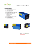
Shenzhen I-Panda New Energy Technology & Science Co., Ltd.
I-P-SMART2-40A/50A/60A
Manual
Contents
1 Notes on this Manual ............................................................................2
2 Safety Instructions................................................................................. 2
3 Unpacking..............................................................................................5
4 Assembly............................................................................................... 6
5 MPPT controller Connection.................................................................7
6 Meaning of LED/LCD and function key............................................10
7 Parameter Setting............................................................................... 12
8 MPPT and PC Connection ............................................................... 13
9 Technical Parameter...........................................................................18
10 Maintenance and Cleaning............................................................ ....20
11 Storage and waste disposal..................................................................21
12 Recovery Processing and Warranty.....................................................21
1. Notes on this Manual
This manual describes how to install and service MPPT solar charge controller.
1.1 Validity
This manual applies to the whole MPPT solar charge controller models produce by
our company:
1.2 Target Group
This manual is intended for the installer and the operator.
1.3 All manuals for the device and installed components must be stored in the
immediate vicinity of the charge controller and must be accessible at all times.
1.4 Symbols Used
The following types of safety messages and general information appear in this
document:
Warning!
WARNING indicates a hazardous situation which, if not avoided, could
result in machine stoppage or serious injury.
Warning!
WARNING indicates a hazardous situation which, if not avoided, could
result in machine stoppage or serious injury.
Note!
In order to operate this device well, please read the operation
instruction carefully.
2. Safety Instructions
2.1 General Safety Instructions
Warning!
Due to high input working voltage, please be cautious, otherwise it is
danger to life.
• All work on the charge controller must only be carried out by an electrically
skilled person.
•The appliance is not to be used by children or persons with reduced physical
sensory or mental capabilities, or lack of experience and knowledge, unless
they have been given supervision or instruction.
•Children should be supervised to ensure that they do not play with the
appliance.
Caution!
Be careful for high temperature enclosure parts.
• Do not touch the enclosure of the charge controller during operation.
Please settle it on the cooling ventilation environment.
Caution!
Radiation is harmful for health.
•Do not stay closer less than 20 cm around the solar charge controller for a
long time.
2.2 Explanation of Symbols
Below is the explanation for all the symbols shown on the device and label.
Symbol
Explanation
Risk of electric shock
Energy stored in capacitors will remain alive for 5 minutes; don’t touch within
the period after disconnection
Both the sides have circuit lines, disconnect both and don’t operate within 5
minutes after disconnection
No self-serviceable parts inside the enclosure, don’t attempt to remove the cover.
Only qualified persons are permitted to operate and maintain the equipment.
Only insulated tools are permitted to use to reduce risks of hazard to individuals.
Beware of hot surface.
The solar charge controller can become hot during operation. Avoid contact
during operation. And never put any goods onto the equipment under load.
● Symbols on the Type Label
Symbol
Explanation
CE FCC CB ROHS mark;
The device complies with the requirements of the applicable CE FCC CB ROHS
guidelines.
●Important Safety Instructions
When using the product, please do remember the below information to avoid the fire,
lightning or other personal injury:
Warning!
Ensure input DC voltage no more than Max. DC voltage .Over voltage may
cause permanent damage to solar charge controller or other losses, which will
not be included in warranty! This chapter contains important safety and
operating instructions. Read and keep this operation guide for future reference.
Warning!
Authorized service personnel must disconnect both DC and battery bank power
from the solar charge controller before attempting any maintenance or cleaning
or working on any circuits connected to the solar charge controller.
● Before using the solar charge controller, please read all instructions and cautionary
markings on the solar charge controller, and all corresponding sections of this
guide.
● Please use components and parts recommended or sold by I-Panda New Energy.
Otherwise may result in a risk of fire, electric shock, or injury to person.
● To avoid a risk of fire and electric shock, make sure that existing wiring is in good
condition and that wire is not undersized. Do not operate the solar charge controller
with damaged or substandard wiring.
● Do not disassemble the solar charge controller. It contains no user-serviceable parts.
See Warranty for instructions on obtaining service. Attempting to repair the solar
charge controller by yourself may result in a risk of electric shock or fire and will
make your warranty invalid.
● To reduce the risk of electric shock, authorized service personnel must use
insulating tool to operate the device.
● Keep away from flammable, explosive materials to avoid fire disaster.
● The installation place should be away from humid or corrosive substance.
● To reduce the chance of short-circuits, authorized service personnel must use
insulated tools when installing or working with this equipment.
3. Unpacking
3.1 Device parts checking:
E
C
A
D
G
F
H
Object
A
B
C
D
E
Quantity
1 unit
2 pc
4 set
2 pc
1 pc
F
G
1 pc
Description
Charge controller
Gallow pulley
screw
joint
232 turn to RJ45
communication cable
User manual
1 pc
Temperature sensing wire
H
2 pc
Fuse wire
If there is any part missing, please contact your dealer.
3.2 Check for Transport Damage
Check the charge controller for visible external damage, such as cracks in the
enclosure. Contact your dealer if you find any damage.
3.3 Identifying the Charge Controller
You can identify the charge controller by the type label. The type label is in the
enclosure.
4. Assembly
4.1 Operator:technical personnel;
4.2 Selecting the Mounting Location
Danger:
Danger to life due to fire or explosion.
The charge controller enclosure can become hot during operation.
• Do not mount the charge controller on flammable construction material.
• Do not mount the charge controller near highly flammable materials.
• Do not mount the charge controller in potentially explosive areas.
• Do not expose the charge controller to direct sunlight to avoid power
loss due to overheating.
Caution:
Danger of burn injuries due to hot enclosure parts.
• Mount the charge controller in such a way that it cannot be touched
inadvertently during operation.
4.2.1 Dimensions
L * W * H:270mm*150mm*88mm
4.2.2 Net Weight
Weight:3kg
4.2.3 Ambient Conditions
• The mounting location and method must be suitable for the weight and dimensions.
• Mount on a solid surface.
• The mounting location must be accessible at all times.
• The charge controller must be easy to remove from the mounting location at any
time.
• The ambient temperature should be between -20 °C and +60 °C to guarantee optimal
operation.
• Do not expose the charge controller to direct sunlight to avoid power losses due to
overheating.
4.2.4 Safety Clearance
Observe the following safety clearance to wall, other devices or objects to ensure
sufficient heat dissipation.
Direction
Sides
Top
Bottom
Safety clearance
20cm
30cm
20cm
5. MPPT controller Connection
5.1 Safety
Danger!
Danger to life due to high voltage in the solar charge controller.
• Disconnect the PV array using a disconnection unit and secure it against
accidental reactivation.
• Disconnect the circuit breaker and ensure that it cannot be reconnected.
• Ensure that no voltage is present in the system.
Warning:
Risk of injury due to electric shock。
If all cables with different voltages are routed in parallel, damaged cable
insulations may lead to a short circuit.
• Route all cables separately.
Warning:
Over voltage can destroy the system.
• Use an external over voltage protector in areas with an increased risk of
thunderstorm and lightning.
5.2 Connections of the PV power system
5.2.1 PV String
Solar charge controller device can be connected in series into 1-strings PV modules.
Please select PV modules with excellent function and reliable quality. Open-circuit
voltage of module arrays connected in series should be less than Max. DC input
Voltage (150V); operating voltage should be conformed to MPPT voltage range.
Please use PV cable to connect modules to device. From junction box to device,
voltage drop is about 1-2%. So we suggest the solar charge controller install near PV
module, in order to save wire and reduce DC loss.
Note:
Please don’t connect the PV panel positive or negative to ground.
Warning:
PV module voltage is very high which belongs to dangerous
voltage range, please comply with electric safety rules when
connecting.
5.2.2 The voltage of battery system and types
1) This controller could charge for DC 12 V/ 24 V/48V battery system . It would
automatic recognition the voltage system :
2) The controller had already been set to charge 4 types battery as following form . If
have other need , the charge parameter also could be reset through machine and solar
eagle . The details please check the illustrate .
The charging voltage of battery type
Bulk Voltage
Battery Type
Vented
Sealed
Gel
NiCd
Floating Voltage
12V
24V
48V
12V
24V
48V
14.2V
28.6V
57.2V
13.2V
26.4V
52.80V
14.2V
28.6V
57.2V
13.4V
26.8V
53.60V
14.2V
28.6V
57.2V
13.7V
27.40V
54.80V
14.2V
28.6V
57.2V
14.0V
28.0V
56.0V
user-defined(Set by the microcomputer software)
In the case battery type is not set , use the default battery type (Gel battery).
Other
5.2.3 The voltage of DC load system and Max current :
This controller had added DC load output function , the output voltage range based on
the type of battery bank system . Like the battery bank voltage is 48V , DC output
voltage range will be the range of 48V battery bank working voltage .
1) How to turn DC output turn on/off ?
Please find the DC output control through MPPT or Solar Eagle software . It have 6
way to control it : ON Mode / OFF Mode / Time Control Mode /PV Volt Ctrl /
PV&Time Ctrl : Details please check the Setting ;
2) How to set the low voltage protection of DC output ?
This controller have low voltage protection ,the magnitude of low voltage protection
Could be set based on customer’s need . Factory settings is 10.5 V for 1 battery .If the
DC output is under the State of providing power for load ,then when the voltage under
the magnitude of low voltage protection , the DC output will stop provide power for
load . When the voltage of battery is recover to 0.5V bigger the magnitude of low
voltage protection ,it will restart . For 48V system , if the DC output under on mode ,
then when the battery bank will stop provide power under 42V , it will restart when
the voltage recover to 42.5 V .
3) Max DC output current
Then Max DC output current is 50A , if the output current out the rated current ,the
built-in fuse will be burn . We provide 2 fuse as back up ;
5.2.4 Specification for cable and micro-breaker
Model
Cable (Cu)
Micro-Breaker
I-P-Smart240A
≥4mm
63 A
I-P-Smart250A
≥4mm
63 A
I-P-Smart260A
≥4mm
63A
Micro-breaker should be installed between DC output and battery. Kindly check the
following picture ( we do not provide built-out breaker ):
5.2.5 MPPT controller work step
Cation : Please follow the steps ,or the machine will be easy to broke .
Please make sure the MPPT had already been connected in right way .
Step 1 : Open the breaker that connect with battery , make sure the MPPT controller
had been connect with with the battery .( When all this done ,the LED and LCD will
show some information )
Step 2 :Turn on the breaker that connect with PV module , if the PV module voltage is
in the charging range , then machine will start to work .
Step 3 : If need DC load control , please set the DC output control mode , then turn on
the DC output breaker .
5.2.6 The step of turn off machine
Cation : Please follow the steps ,or the machine will be easy to broke .
Step 1 : Turn off the PV input breaker ,make sure PV and controller disconnect .
Step 2: Turn off the battery breaker , the machine will be complete off .
Warning:When the controller is charging for battery , please
do not turn off the breaker with battery before PV input have
not turn off . Or the machine will have unrecoverable fault
and this will not in the warranty .
6、Meaning of LED/LCD and function key
6.1
Panel Description
Meaning of LED and function key
ALARM (Red) ----- Alarm Light ( Red , when controller in fault state this light
will on . )
CHANGE(Blue)
----- Charging Light ( Blue ,when controller start to charge
power ,this light will on .)
LOAD(Green)------- Load Light (Green , when the DC load turn on ,this load will
on )
UP
----------- UP Function Key (For check or page up and numerical increase )
DOWN ------- DOWN Function Key ( For check or page up and numerical
reduction )
ENTER ------------------ ENTER key ( For enter in )
ESC ------------------- ESC Key ( For exit and save data )
6.2 Charge Mode
This controller have 3 mode :Constant charging stage ( CC Mode ) , Constant voltage
charging stage ( CV Mode ) , Floating charge Stage ( FC Mode ) :
In CC Mode ,the blue light will flash for every second .
In CV Mode ,the blue light will flash for every 3 second .
In CF Mode ,the light will keep on .
( Note : Charging Mode also could check in LCD and solar eagle .)
Menu
No.
1
2
3
Menu Type
Menu Description
Work Status
Setting
Information
For check the charging state
Parameter set
For check the parameter
6.3.1 The information of LCD display in different menu .
SMART 2
MPPT LCD INFORMATION
Note
If is charging ,it will have
information
Charing Mode
Time
If connect temperature
sensing wire ,then will show
temperature
Chg Cur(Charge current)
Chg Model(Charging Mode)
Time
Bat Temp(The real time temperature)
Work
Status
Buck Temp(The main real time temperature)
PV Volt(Solar panel voltage)
Chg Power(Real time charge power )
Bat Volt(Battery real time voltage)
Vented
PV input voltage
Charging power
Show battery voltage , if is
charging , it will show
charging voltage .
Will show fault mode under
fault state
Battery type set
Bat Type Sel
Setting
User Bat Set
Gel
Nicd
Sealed
User Def
Bulk Volt Set
Special battery ,just need to set
Main charging voltage and
float charging voltage .Please
based on one battery .
Float
Max Chg Cur Set
Setting
Date Set
Time
Gate Address Set
Port Set
IP Address Set
Load Control
Time Control
Load Off Bat Volt
On/Off Mode
PV Volt Ctrl
PV & Time Ctrl
Information
Bat Chg SYS
Total power
Firmware Ver.
Machine ID
Bat Type
IP Address
Port
Time Load Ctrl
Could set any data under rated
number
Date Set
Time Set
Gate Address Set
Port Set
IP Address Set
Set the double time to control
the DC load output on / off
Set the low voltage protection
of battery . ( Based on one
battery )
Keep on / off state
Could set the PV voltage to
control DC load output turn
on/off
Could set the PV voltage and
time to control DC load output
turn on/off
System Voltage
Total energy from this machine
Firmware Ver.
Machine ID
Battery Type display
IP Address
Port Number
Last time load control mode
7、 Parameter Setting
When controller connect with battery and it is in on state ,the controller will show the
information of Work Status .
7.1 Could be set parameter of MPPT
Please check the details under Setting Interface
7.2 The steps of setting
Press ESC into main menu ----> Press down to change the page to
setting---->Press ENTER to get in ---->to press down to chose the information need
be set .For example :
Press ESC into main menu ----> Press down to change the page to
setting---->Press ENTER to get in ---->Press DOWN to change to load
control---->Press ENTER to get in ---->Press DOWN to On/Off Mode---->Press
ENTER to get in ----> Press UP or down to Load On mode---->Press ESC to save and
exit .
8、MPPT and PC Connection
8.1 Solar Eagle introduction
Our company had develop PC operational software , customer check all
information of solar system and change some parameters , if have our company
accredit, even could change some original parameters . The solar eagle are as
following picture :
overview: Get into main interface as following
Com Setting ( Com):Get into set the connection of Solar Eagle and PC .
Setting:Get into battery type set and load control set interface
Data:MPPT working status
Event Log :MPPT working status per day
Login :Some parameters set need administrator’s pass word .
8.2
Then connection of MPPT and Solar Eagle .
Could connect trough RS 232 ( COM ) or ( TCP/IP)
8.2.1 Connect through RS232 ( COM )
1)Customer’s PC have RS232 connector , check the following picture
Step 1 : Please install Solar Eagle ,details please kindly check install steps .
Step 2 : Installed and connected controller ,and make sure controller under on state
(after controller connect battery ,the controller will automatic start )
Step 3:Connect PC and controller with RS232 ,make sure they had been connect ,PC
will notice com ,at this time the PC will chose COM1 :
Step 4:Open Solar Eagle ( WIN 7
administrator ) ,then press
automatic connect :
, WIN 8 system ,please open as
to chose COM communication and enter ,it will
Step 5 : After all these steps ,the information could be check on Solar Eagle .If need to
set special parameters ,please ask our company to accredit .
2) Customer do not have PC connector .
If customer do not have RS232 connector , then customer need to prepare a USB
to RS232 connector like the following picture :
Step 1: Please install USB to RS232 driver software and make sure it had been
connect with RS232 . The other step is same as above .
8.2.2
Connect through LAN ( TCP/IP )
1)Connect through RJ45 ,like the following picture
Step 1 : Please install Solar Eagle ,details please kindly check install steps .
Step 2 : Installed and connected controller ,and make sure controller under on state
(after controller connect battery ,the controller will automatic start )
Step 3: Connect PC and controller through RJ45 .
Step 4:
First way :Based on PC GATED ADDRESS and IP ADDRESS to set the
controller’s PC GATED ADDRESS and IP ADDRESS . But please note the last
number of IP address should keep different .Like : PC’s PC GATED ADDRESS is
192.168.1.1 ,IP ADDRESS is 192.168.1.10 , then set of controller is GATED
ADDRESS is 192.168.1.1 ,IP ADDRESS is 192.168.1.8 : Make sure controller and
PC in the same LAN .
Second way :Based on PC GATED ADDRESS and IP ADDRESS to set the
controller’s PC GATED ADDRESS and IP ADDRESS . But please note the last
number of IP address should keep different .Like : Controller’s GATED ADDRESS is
192.168.1.1 ,IP ADDRESS is 192.168.1.10 , then set of PC’s GATED ADDRESS is
192.168.1.1 ,IP ADDRESS is 192.168.1.8 : Make sure controller and PC in the same
LAN .
Step 5: Open Solar Eagle ( WIN 7 ,WIN 8 system ,please open as
administrator ) ,then press
to chose TCP/IP communication and fill IP address
and port number ,enter ; It will automatic connect in 10s : If could not connect , please
make sure controller and PC in the same LAN and restart controller .
1)Connect through router as following picture ;
Step 1 : Please install Solar Eagle ,details please kindly check install steps .
Step 2 : Installed and connected controller ,and make sure controller under on state
(after controller connect battery ,the controller will automatic start )
Step 3: Connect controller and router through RJ45 .Then add PC into LAN.
Step4: Set controller and PC’s GARE ADRESS based on router’s GATE
ADRESS .Keep them in the same LAN . Like : router’s GATE ADRESS is
192.168.1.1 ,then controller and PC’s GARE ADRESS should be 192.168.1.1 .
Step 5 : IP ADRESS setting
Set the controller and PC’s IP address ,based on GATE ADDRESS to set IP
ADDRESS , the last number should be different :Like IP’s GATE ADRESS is
192.168.1.1 ,PC’s IP ADDRESS should be 192.168.1.10 ,the controller’s IP
ADDRESS should be 192.168.1.5;
Step 6: Open Solar Eagle ( WIN 7 ,WIN 8 system ,please open as
administrator ) ,then press
to chose TCP/IP communication and fill IP address
and port number ,enter ; It will automatic connect in 10s : If could not connect , please
make sure controller and PC in the same LAN and restart controller .
8.2.3
Usage of Solar Eagle
When Solar Eagle have been connect ,customer could check and change some
parameters;
If have some special parameters need to be change , please purchase pass from our
company :
Step 1;Contact us to have password
Step 2:Login
Step 3:Change parameters
9、Parameters
Model:I-P-SMART2-40A/50A/60A -series
40A
50A
60A
Charge Mode
Maximum Power Point Tracking
Method
3 stages: fast charge(MPPT),constant voltage, floating charge
System Type
DC12V/24V/48V
Automatic recognition
12V system
DC9V~DC15V
24V system
DC18V~DC30V
48Vsystem
DC36V~DC60V
Soft Start Time
12V/24V/48Vsyste
m
≤10S
Dynamic Response
Recovery Time
12V/24V/48Vsyste
m
500us
Conversion
Efficiency
12V/24V/48Vsyste
m
≥96.5%,≤99%
System Voltage
PV Modules
Utilization Rate
12V/24V/48Vsyste
m
≥99%
Input Characteristics
12V system
DC18V~DC150V
24V system
DC34~DC150V
48V system
DC65~DC150V
12V system
DC16V
24V system
DC30V
48V system
DC60V
Low Voltage Input
12V system
DC22V
Recovery Point
24V system
DC34V
48V system
DC65V
Max DC Voltage
12V/24V/48V
system
DC160V
Input Overvoltage
Protection Point
12V/24V/48V
system
DC150
Input Overvoltage
Recovery Point
12V/24V/48V
system
DC145V
MPPT Working
Voltage and Range
Low Voltage Input
Protection Point
Max. PV Power
12V system
570W
700W
900W
24V system
1130W
1400W
1700W
48V system
2270W
2800W
3400W
Output Characteristics
Selectable Battery
Types (Default type
is GEL battery)
12V/24V/48Vsyste
m
Constant Voltage
12V/24V/48V
system
Floating Charge
Voltage
12V/24V/48V
system
Over Charge
Protection Voltage
Sealed lead acid, vented, Gel, NiCd battery
(Other types of the batteries also can be defined)
Please check the charge voltage according to the battery
type form.
12V system
14.6V
24V system
29.2V
48V system
58.4V
Rated Output
Current
12V/24V/48V
system
40A
50A
60A
Current-limiting
Protection
12V/24V/48V
system
44A
55A
66A
Rate charge current
12V/24V/48V
System
40A
50A
60A
Temperature Factor
12V/24V/48V
system
±0.02%/℃
Temperature
Compensation
12V/24V/48V
system
14.2V-(The highest temperature-25℃)*0.3
Output
12V/24V/48V
200mV
Ripples(peak)
system
Output Voltage
Stability Precision
12V/24V/48V
system
≤±1.5%
Charge voltage
Peak-Peak Ripple
12V/24V/48V
System
200mV
Charger voltage
accuracy
12V/24V/48V
System
≤±1.5%
Discharge characteristic
Setting Control
Controller or LAN
Max discharge
current
12V/24V/48V
System
40A
Discharge
protection
12V/24V/48V
System
fuse 30A*2
Double-time control
12V/24V/48V
System
ON / OFF mode
12V/24V/48V
System
ON / OFF
PV voltage control
12V/24V/48V
System
PV voltage on,PV voltage off
PV voltage / time
delay control
12V/24V/48V
System
PV voltage on,time delay off
Discharge voltage
protection
12V/24V/48V
System
Output off when it under setting voltage; Factory set is
10.5 .( Note : set based on 1 battery )
On in morning ,off in morning / On in night ,off in night
Communication Features
RS232
Communication
12V/24V/48V
System
Chose COM communication
LAN
Communication
12V/24V/48V
System
Set IP and Gate address for controller and solar
eagle ;Then chose TCP communication
Protection
Input Low Voltage Protection
Check the input characteristics
Input Overvoltage Protection
Check the input characteristics
Input Polarity Reversal Protection
yes
Output Overvoltage Protection
Check the output characteristics
Output Polarity Reversal Protection
yes
Short-circuit Protection
Recover after eliminating the Short-circuit fault, no
problem for long term Short-circuit
Temperature Protection
95℃
Temperature protection
Above 85℃,decrease the output power, decrease 3A per
degree.
Other Parameters
Noise
≤40dB
Thermal methods
Forced air cooling, fan speed rate regulated by
temperature, when inner temperature is too low, fan ran
slowly or stop; when controller stop working, fan also stop
ran.
Components
World brand raw materials. Compliance with EU
standards. All rated temperature of electrolytic capacitors
not less than 105℃
Smell
No peculiar smell and toxic substances.
Environment Protection
Meet the 2002/95/EC,no cadmium hydride and fluoride
Physical
Measurement DxWxH (mm)
270*185*90
N.G(kg)
3
G.N(kg)
3.6
Color
Blue/Green (optional)
Safety
CE, RoHS, PSE,FCC
EMC
EN61000
Type of Mechanical Protection
IP21
Environment
Humidity
0~90%RH ( no condense)
Altitude
0~3000m
Operating Temperature
-20℃ ~ +40℃
Storage Temperature
-40℃ ~ +75℃
Atmospheric Pressure
70~106kPa
10. Maintenance and Cleaning
10.1 Replacing the Thermal Fuses
Using incorrect thermal fuses may irreparably damage the solar charge controller.
• Only use the thermal fuses included in the scope of delivery
1. Open the solar charge controller as described in section "Opening the solar charge
controller"
2. Remove the broken thermal fuses from the sockets (A and B).
3. Insert new thermal fuses (included in the scope of delivery).
4. Close the solar charge controller as described in section "Closing the solar charge
controller".
Location of Thermal Fuses
10.2 Cleaning the Cooling Fin
Clean the Fan air vents and internal cooling fin regularly by using the dry or small wet
cloth to wipe.
Attention:
• Liquid detergent or corrosive solvent cleaning are forbidden.
• Liquid is not allowed to down in the device.
• Make the air vent open.
•Carefully remove dirt with a suitable soft brush.
11. Storage and waste disposal.
10.1 Store the charge controller in a dry place with ambient temperatures between -40
°C and +75 °C.
10.2 Disposal
Dispose of the solar charge controller at the end of its service life in accordance with
the disposal regulations for electronic waste which apply at the installation site at that
time.
12. Recovery Processing and Warranty
12.1 Recovery Processing
When the controller abnormal, please check the following question and contact the
customer service representative.
11.1.1 Controller failure mode:
Please check the fault tips in the failure mode, and then proceed to the appropriate
troubleshooting;
11.1.2 When the controller does not start properly:
1. Check the controller external solar panels with the correct polarity.
2. Check Battery Connection;
3. Check Battery;
4. Check circuit breaker;
5. Check internal fuse;
If the problem persists , please contact the customer service;
Please offer the following information : Equipment information: Model, Order No.,
serial-number(Stickers on the rear plate); Detailed description of the problem
(Type of system, occasionally/frequent problems, indicator light, data display, and so
on ).
12.2 Warranty
Within the warranty period, it is free to repair for the non-human fault. Otherwise,
should charge the cost of repairs.
12.3 Guarantee Card
User name:
Address:
Telephone Number:
Email:
Date of Purchase:
Date of Installation:
Installer Contact Information:
Solar Charge Controller Serial Number:
Battery Voltage:
PV Module Type and Manufacturer:
Array Wattage:
Country:
Pose Code:
Vendor:
Installer:
PV Voltage:
Notes: