1
BreezeMAX® Mini-Centralized
ASN-GW
System Manual
Release Version: 3.5
December 2011
P/N 215971
Document History
Document History
Topic
Description
Date Issued
BreezeMAX Mini-Centralized
ASN-GW
This is the document’s first release
November 2009
Using the History Feature
Section 3.1.4.3
Updated-up to 14 previously executed
commands can be displayed
February 2010
Configuring the MTU for physical
interfaces
Section 3.3.2.1.2.5
Updated default values
Adding a Static Route
Section 3.3.7.1
Updated description of ip_nexthop
Managing AAA Client
Configuration
Section 3.3.9.9.1
Added support for AAA server
redundancy.
Managing Global RADIUS
Configuration Parameters
Section 3.3.9.9.2
Added alrmAaaSwitchoverRetryFailThrshld
Configuring the DHCP Relay
Option 82 Parameters
Section 3.3.9.10.4.4.2
Added new option to Subopt1value and
Subopt2value
Managing Service Interfaces
Section 3.3.9.8
removed mtu (changed to vendor
parameter)
Configuring IP Interfaces
Section 3.3.2.3
removed mtu (changed to vendor
parameter)
Managing the Time Settings
Parameters
Section 3.3.12.3
Updated to reflect support of managing
SNTP parameters and daylight saving
parameters.
Managing the Data Path Function
Section 3.3.9.3
Updated to reflect the ability to configure
the throughput-threshold parameter.
Managing the Context Function
Section 3.3.9.4
Updated to reflect the ability to configure
the ms-capacity-threshold parameter.
Managing the Hot-Lining Feature
Section 3.3.9.13
New
Manual MS De-registration
Section 3.4.1
Updated-added the options to de-register
am MS by its MSID (MAC address) and
de-register all MSs served by a specified
BS.
BreezeMAX Mini-Centralized ASN-GW System Manual
ii
Document History
Topic
Description
Date Issued
Displaying MS Information
Section 3.4.2
New display option
February 2010
Configuring Parameters for IP-IP
Service Interface
Section 3.3.9.8.2.1
Updated Description, Presence and Default
Value for srcaddr and dstaddr.
Configuring Parameters for VLAN
Service Interface
Section 3.3.9.8.2.2
Updated Description, Presence and Default
Value for vlan-id and dflt-gw-ip.
Configuring DHCP Server
Parameters
Section 3.3.9.10.4.2.1
Updated default value of opt60.
Specifying DHCP Proxy
Configuration Parameters
Section 3.3.9.10.4.3.1
Updated default value of opt60.
Configuring the DHCP Relay
Parameters
Section 3.3.9.10.4.4.1
Updated Description, Presence and Default
Value of server-addr.
Configuring Classification Rules
Section 3.3.9.11.4
Updated and corrected the sections related
to L2 classifiers.
Configuring Performance Data
Collection
Section 3.3.11
Updated section content, updated
supported counters groups.
Monitoring Software Components
Removed (display of real-time counters not
supported by CLI)
Displaying Statistics for Physical
and IP Interfaces
Removed (display of real-time counters not
supported by CLI)
Displaying the VLAN Translation
Entries
Section 3.3.2.1.7
Updated command syntax
Configuring Logging
Section 3.3.10
Updated severity levels for module level
logging (Alert, Error and Info levels are
supported)
Displaying the Current Log
Destination
Section 3.3.10.1.4
Updated display format
Displaying the Current Status of
Trace Destinations
Section 3.6.1.1.3
Updated display format
BreezeMAX Mini-Centralized ASN-GW System Manual
April 2010
June 2010
iii
Document History
Topic
Description
Date Issued
Configuring the Unique Identifier
Section 3.3.2.3.8
Updated range for site id
June 2010
Resetting the system
Section 3.2.2.1
Updated command syntax and command
mode
Testing Connectivity to an IP
Interface
Section 3.3.2.3.8
New command (ping test)
Configuring Parameters for the
PHS Rule
Section 3.3.9.12.2
Corrected definition for verify (in Possible
Values)
Specifying Service Flow
Configuration Parameters
Section 3.3.9.11.3.3.2
Updated Possible Value range for
media-type (up to 15)
Version 3.0.10
December 2010
Downgrading procedure
Section A.3
New section, new command (allow
migration)
July 2011
General Description
Section 1.3
Updated: Stackable solution is supported,
aggregate throughput up to 200Mbps is
not dependent on license.
Configuring Performance Data
Collection
Section 3.3.11
Updated: Added AAAClient to NPU
Counters
Managing QoS Classification Rules
Section 3.3.6.2
Added rule (in two places): Default
(pre-configured) QoS classification rules
cannot be deleted
Assigning an IP address to an
interface
Section 3.3.2.3.3
Updated configuration rules
Configuring Static Routes
Section 3.3.7
Added caution note related to routes for
SNMP Trap Managers/TFTP Servers created
by a management system.
Configuring the Trap Manager
Section 3.3.12.2
Added note -recommended to manage
Trap Managers from the management
system.
Enabling System-level Logging
Section 3.3.10.1.1
Added note -recommended to manage
Log TFTP Server from the management
system.
BreezeMAX Mini-Centralized ASN-GW System Manual
iv
Document History
Topic
Description
Date Issued
Upgrading the NPU
Section A.2.1.1
Added note -recommended to manage
TFTP Server IP Address from the
management system
July 2011
Configuring the SNTP Server(s)
Section 3.3.12.3.2
Added note -recommended to manage
SNTP Server(s) IP Address from the
management system
Commissioning - Completing the
Site Configuration Using
AlvariSTAR
Section 2.2
Added full details
Commissioning - Connectivity
Mode
Section 2.1.3.1
Updated
Commissioning - Static Route
Definition
Section 2.1.4
Updated
Tracing
Removed: Section
Updated: Sections 3.2.1, 3.2.2.1,
3.3.10, 3.3.10.1.1, 3.3.10.1.3,
3.3.10.1.5, 3.3.10.1.6,
3.3.12.3.3, 3.5.2
Tracing is managed only by the vendor
Configuring Parameters for the
AAA Client
Section 3.3.9.9.1.2
Updated configuration rules for
aaaRedundancy: If enabled - the
ip-address of the active server (primary or
alternate) cannot be modified.
Upgrading the NPU - Step 2:
Triggering Software Download
Section A.2.1.2
Added more possible reasons for error
Configuring the External Ether
type
Section 3.3.2.2.1
Updated default value to 8100
Managing Service Groups
Section 3.3.9.10
Added support for a new type of service
group: VPLS Hub and Spoke.
Total number of service groups updated to
80 (total number of IP and VPWS service
groups is limited to a maximum of 10).
BreezeMAX Mini-Centralized ASN-GW System Manual
v
Document History
Topic
Description
Date Issued
Managing Service Interfaces
Section 3.3.9.8
Added support for a new type of service
interface: VPLS Trunk.
July 2011
Total number of service interfaces updated
to 80 (total number of IP-IP, VLAN and
QinQ service interfaces is limited to a
maximum of 10).
Configuring the Parameter for the
Data Path Function
Section 3.3.9.3.1
Updated default value of
throughput-threshold to 500.
Configuring the Parameter for the
Context Function
Section 3.3.9.4.1
Updated default value of
ms-capacity-threshold to 3000
Configuring Parameters for VLAN
Service Interface
Section 3.3.9.8.2.2
Updated configuration rules for vlan-id.
Configuring Parameter for QinQ
Service Interface
Section 3.3.9.8.2.3
Updated configuration rules for vlan-id.
Configuring/Modifying the VLAN
ID for an IP Interface
Section 3.3.2.3.5
Updated configuration rules for VLAN IDs
of IP interfaces.
Configuring DHCP Server
Parameters
Section 3.3.9.10.4.2.1
Updated default value and improved
description for opt60.
Specifying DHCP Proxy
Configuration Parameters
Section 3.3.9.10.4.3.1
Configuring Service Flows
Section 3.3.9.11.3.3
Updated configuration rules for grp-alias
Configuring Uplink/Downlink
Classification Rule Names
Section 3.3.9.11.3.3.4
Updated configuration rules for rulename
Specifying the port speed
Section 3.3.2.1.2.4
The default for all ports (including Data
and CSCD ports) is 100 Mbps
Configuring the Local Switching
Parameter of a VPLS Service Group
Section 3.3.9.10.8.4
Added parameter
BreezeMAX Mini-Centralized ASN-GW System Manual
September 2011
vi
Document History
Topic
Description
Date Issued
Handling Traffic in a VPLS Hub and
Spoke Service Group
Section 3.3.9.10.10
New section that provides details on
handling uplink/downlink traffic in VPLS
Hub and Spoke services, and describes
how to view relevant MAC Address tables
information and how to clear these tables.
September 2011
Configuring the DHCP Server
Section 3.3.9.10.4.2
Updated default value of Opt60
Privilege Levels
Section 3.1.4.5
Improved
Managing Users and Privileges
Section 3.1.5
Corrected and improved
Terminating the Session
Section 3.1.7.3
New section
BreezeMAX Mini-Centralized ASN-GW System Manual
vii
Legal Rights
Legal Rights
© Copyright 2011 Alvarion Ltd. All rights reserved.
The material contained herein is proprietary, privileged, and confidential and owned by Alvarion or its
third party licensors. No disclosure thereof shall be made to third parties without the express written
permission of Alvarion Ltd.
Alvarion Ltd. reserves the right to alter the equipment specifications and descriptions in this publication
without prior notice. No part of this publication shall be deemed to be part of any contract or warranty
unless specifically incorporated by reference into such contract or warranty.
Trade Names
Alvarion®, BreezeCOM®, WALKair®, WALKnet®, BreezeNET®, BreezeACCESS®, BreezeMAX®,
BreezeLITE®, 4Motion®, and/or other products and/or services referenced here in are either registered
trademarks, trademarks or service marks of Alvarion Ltd.
All other names are or may be the trademarks of their respective owners.
“WiMAX Forum” is a registered trademark of the WiMAX Forum. “WiMAX,” the WiMAX Forum logo,
“WiMAX Forum Certified”, and the WiMAX Forum Certified logo are trademarks of the WiMAX Forum.
Statement of Conditions
The information contained in this manual is subject to change without notice. Alvarion Ltd. shall not be
liable for errors contained herein or for incidental or consequential damages in connection with the
furnishing, performance, or use of this manual or equipment supplied with it.
Warranties and Disclaimers
All Alvarion Ltd. (“Alvarion“) products purchased from Alvarion or through any of Alvarion's authorized
resellers are subject to the following warranty and product liability terms and conditions.
Exclusive Warranty
(a) Alvarion warrants that the Product hardware it supplies and the tangible media on which any
software is installed, under normal use and conditions, will be free from significant defects in materials
and workmanship for a period of fourteen (14) months from the date of shipment of a given Product to
Purchaser (the "Warranty Period"). Alvarion will, at its sole option and as Purchaser's sole remedy, repair
or replace any defective Product in accordance with Alvarion' standard R&R procedure.
(b) With respect to the Firmware, Alvarion warrants the correct functionality according to the attached
documentation, for a period of fourteen (14) month from invoice date (the "Warranty Period")". During
the Warranty Period, Alvarion may release to its Customers firmware updates, which include additional
performance improvements and/or bug fixes, upon availability (the "Warranty"). Bug fixes, temporary
patches and/or workarounds may be supplied as Firmware updates.
Additional hardware, if required, to install or use Firmware updates must be purchased by the Customer.
Alvarion will be obligated to support solely the two (2) most recent Software major releases.
ALVARION SHALL NOT BE LIABLE UNDER THIS WARRANTY IF ITS TESTING AND EXAMINATION DISCLOSE
THAT THE ALLEGED DEFECT IN THE PRODUCT DOES NOT EXIST OR WAS CAUSED BY PURCHASER'S OR
ANY THIRD PERSON'S MISUSE, NEGLIGENCE, IMPROPER INSTALLATION OR IMPROPER TESTING,
UNAUTHORIZED ATTEMPTS TO REPAIR, OR ANY OTHER CAUSE BEYOND THE RANGE OF THE INTENDED
USE, OR BY ACCIDENT, FIRE, LIGHTNING OR OTHER HAZARD.
Disclaimer
BreezeMAX Mini-Centralized ASN-GW System Manual
viii
Legal Rights
(a) The Software is sold on an "AS IS" basis. Alvarion, its affiliates or its licensors MAKE NO
WARRANTIES, WHATSOEVER, WHETHER EXPRESS OR IMPLIED, WITH RESPECT TO THE SOFTWARE AND
THE ACCOMPANYING DOCUMENTATION. ALVARION SPECIFICALLY DISCLAIMS ALL IMPLIED
WARRANTIES OF MERCHANTABILITY AND FITNESS FOR A PARTICULAR PURPOSE AND
NON-INFRINGEMENT WITH RESPECT TO THE SOFTWARE. UNITS OF PRODUCT (INCLUDING ALL THE
SOFTWARE) DELIVERED TO PURCHASER HEREUNDER ARE NOT FAULT-TOLERANT AND ARE NOT
DESIGNED, MANUFACTURED OR INTENDED FOR USE OR RESALE IN APPLICATIONS WHERE THE
FAILURE, MALFUNCTION OR INACCURACY OF PRODUCTS CARRIES A RISK OF DEATH OR BODILY
INJURY OR SEVERE PHYSICAL OR ENVIRONMENTAL DAMAGE ("HIGH RISK ACTIVITIES"). HIGH RISK
ACTIVITIES MAY INCLUDE, BUT ARE NOT LIMITED TO, USE AS PART OF ON-LINE CONTROL SYSTEMS IN
HAZARDOUS ENVIRONMENTS REQUIRING FAIL-SAFE PERFORMANCE, SUCH AS IN THE OPERATION OF
NUCLEAR FACILITIES, AIRCRAFT NAVIGATION OR COMMUNICATION SYSTEMS, AIR TRAFFIC CONTROL,
LIFE SUPPORT MACHINES, WEAPONS SYSTEMS OR OTHER APPLICATIONS REPRESENTING A SIMILAR
DEGREE OF POTENTIAL HAZARD. ALVARION SPECIFICALLY DISCLAIMS ANY EXPRESS OR IMPLIED
WARRANTY OF FITNESS FOR HIGH RISK ACTIVITIES.
(b) PURCHASER'S SOLE REMEDY FOR BREACH OF THE EXPRESS WARRANTIES ABOVE SHALL BE
REPLACEMENT OR REFUND OF THE PURCHASE PRICE AS SPECIFIED ABOVE, AT ALVARION'S OPTION.
TO THE FULLEST EXTENT ALLOWED BY LAW, THE WARRANTIES AND REMEDIES SET FORTH IN THIS
AGREEMENT ARE EXCLUSIVE AND IN LIEU OF ALL OTHER WARRANTIES OR CONDITIONS, EXPRESS OR
IMPLIED, EITHER IN FACT OR BY OPERATION OF LAW, STATUTORY OR OTHERWISE, INCLUDING BUT
NOT LIMITED TO WARRANTIES, TERMS OR CONDITIONS OF MERCHANTABILITY, FITNESS FOR A
PARTICULAR PURPOSE, SATISFACTORY QUALITY, CORRESPONDENCE WITH DESCRIPTION,
NON-INFRINGEMENT, AND ACCURACY OF INFORMATION GENERATED. ALL OF WHICH ARE EXPRESSLY
DISCLAIMED. ALVARION' WARRANTIES HEREIN RUN ONLY TO PURCHASER, AND ARE NOT EXTENDED
TO ANY THIRD PARTIES. ALVARION NEITHER ASSUMES NOR AUTHORIZES ANY OTHER PERSON TO
ASSUME FOR IT ANY OTHER LIABILITY IN CONNECTION WITH THE SALE, INSTALLATION, MAINTENANCE
OR USE OF ITS PRODUCTS.
Limitation of Liability
(a) ALVARION SHALL NOT BE LIABLE TO THE PURCHASER OR TO ANY THIRD PARTY, FOR ANY LOSS OF
PROFITS, LOSS OF USE, INTERRUPTION OF BUSINESS OR FOR ANY INDIRECT, SPECIAL, INCIDENTAL,
PUNITIVE OR CONSEQUENTIAL DAMAGES OF ANY KIND, WHETHER ARISING UNDER BREACH OF
CONTRACT, TORT (INCLUDING NEGLIGENCE), STRICT LIABILITY OR OTHERWISE AND WHETHER BASED
ON THIS AGREEMENT OR OTHERWISE, EVEN IF ADVISED OF THE POSSIBILITY OF SUCH DAMAGES.
(b) TO THE EXTENT PERMITTED BY APPLICABLE LAW, IN NO EVENT SHALL THE LIABILITY FOR DAMAGES
HEREUNDER OF ALVARION OR ITS EMPLOYEES OR AGENTS EXCEED THE PURCHASE PRICE PAID FOR
THE PRODUCT BY PURCHASER, NOR SHALL THE AGGREGATE LIABILITY FOR DAMAGES TO ALL PARTIES
REGARDING ANY PRODUCT EXCEED THE PURCHASE PRICE PAID FOR THAT PRODUCT BY THAT PARTY
(EXCEPT IN THE CASE OF A BREACH OF A PARTY'S CONFIDENTIALITY OBLIGATIONS).
Radio Frequency Interference Statement
The Base Transceiver Station (BTS) equipment has been tested and found to comply with the limits for a
class A digital device, pursuant to ETSI EN 301 489-1 rules and Part 15 of the FCC Rules. These limits are
designed to provide reasonable protection against harmful interference when the equipment is operated
in commercial, business and industrial environments. This equipment generates, uses, and can radiate
radio frequency energy and, if not installed and used in accordance with the instruction manual, may
cause harmful interference to radio communications. Operation of this equipment in a residential area is
likely to cause harmful interference in which case the user will be required to correct the interference at
the user's own expense.
R&TTE Compliance Statement
BreezeMAX Mini-Centralized ASN-GW System Manual
ix
Legal Rights
This equipment complies with the appropriate essential requirements of Article 3 of the R&TTE Directive
1999/5/EC.
Lithium Battery
The battery on the NPU card is not intended for replacement.
Caution
To avoid electrical shock, do not perform any servicing unless you are qualified to do so.
Line Voltage
Before connecting this instrument to the power line, make sure that the voltage of the power source
matches the requirements of the instrument.
Disposal of Electronic and Electrical Waste
Disposal of Electronic and Electrical Waste
Pursuant to the WEEE EU Directive electronic and electrical waste must not be disposed of with unsorted waste.
Please contact your local recycling authority for disposal of this product.
BreezeMAX Mini-Centralized ASN-GW System Manual
x
Important Notice
Important Notice
This user manual is delivered subject to the following conditions and restrictions:
This manual contains proprietary information belonging to Alvarion Ltd. Such information is supplied
solely for the purpose of assisting properly authorized users of the respective Alvarion products.
No part of its contents may be used for any other purpose, disclosed to any person or firm or
reproduced by any means, electronic and mechanical, without the express prior written permission of
Alvarion Ltd.
The text and graphics are for the purpose of illustration and reference only. The specifications on
which they are based are subject to change without notice.
The software described in this document is furnished under a license. The software may be used or
copied only in accordance with the terms of that license.
Information in this document is subject to change without notice. Corporate and individual names
and data used in examples herein are fictitious unless otherwise noted.
Alvarion Ltd. reserves the right to alter the equipment specifications and descriptions in this
publication without prior notice. No part of this publication shall be deemed to be part of any
contract or warranty unless specifically incorporated by reference into such contract or warranty.
The information contained herein is merely descriptive in nature, and does not constitute an offer for
the sale of the product described herein.
Any changes or modifications of equipment, including opening of the equipment not expressly
approved by Alvarion Ltd. will void equipment warranty and any repair thereafter shall be charged for.
It could also void the user's authority to operate the equipment.
Some of the equipment provided by Alvarion and specified in this manual, is manufactured and
warranted by third parties. All such equipment must be installed and handled in full compliance with the
instructions provided by such manufacturers as attached to this manual or provided thereafter by
Alvarion or the manufacturers. Non-compliance with such instructions may result in serious damage
and/or bodily harm and/or void the user's authority to operate the equipment and/or revoke the
warranty provided by such manufacturer.
BreezeMAX Mini-Centralized ASN-GW System Manual
xi
About This Manual
About This Manual
This manual describes the Mini-Centralized ASN-GW, and details how to operate and manage it.
This manual is intended for technicians responsible for setting and operating the Mini-Centralized
ASN-GW equipment, and for system administrators responsible for managing the system. For details on
installing the equipment refer to the relevant Installation Manual.
This manual contains the following chapters and appendices:
Chapter 1 - System description: Describes the Mini-Centralized ASN-GW and its functionality.
Chapter 2 - Commissioning: Describes how to configure basic parameters and validate units'
operation.
Chapter 3 - Operation and Administration Using the CLI: Describes how to use the Command
Line Interface (CLI) for configuring parameters, checking system status and monitoring performance.
Appendix A - Software Upgrade: Describes how to load new software files using TFTP, and how to
switch to a new software version.
BreezeMAX Mini-Centralized ASN-GW System Manual
xii
Contents
Contents
Chapter 1 - System Description ............................................................................. 1
1.1 About WiMAX .......................................................................................................2
1.2 WiMAX Network Reference Model ........................................................................3
1.2.1
Access Service Network (ASN) ............................................................................ 4
1.2.2
Connectivity Service Network (CSN) .................................................................... 4
1.2.3
Network Access Provider (NAP)........................................................................... 4
1.2.4
Network Service Provider (NSP) .......................................................................... 5
1.2.5
Base Station (BS)................................................................................................. 5
1.2.6
ASN Gateway (ASN-GW) ...................................................................................... 5
1.2.7
Reference Points ................................................................................................. 7
1.3 The Mini-Centralized ASN-GW ...............................................................................9
1.4 Specifications ....................................................................................................11
1.4.1
Data Communication (Ethernet Interfaces)....................................................... 11
1.4.2
Configuration and Management ........................................................................ 11
1.4.3
Standards Compliance, General ......................................................................... 12
1.4.4
Environmental ................................................................................................... 12
1.4.5
Mechanical and Electrical................................................................................... 13
Chapter 2 - Commissioning .................................................................................. 14
2.1 Initial Unit Configuration ....................................................................................15
2.1.1
Introduction....................................................................................................... 15
2.1.2
Clearing Previous Configuration ........................................................................ 15
2.1.3
Site Connectivity................................................................................................ 15
2.1.4
Static Route Definition ...................................................................................... 17
2.1.5
SNMP Manager and Trap Manager Definition .................................................... 17
2.1.6
Site ID Definition ............................................................................................... 18
2.1.7
Saving the Configuration ................................................................................... 18
2.2 Completing the Configuration Using AlvariSTAR ..................................................18
2.2.1
Connectivity Configuration ................................................................................ 18
2.2.2
Equipment Configuration - GPS ......................................................................... 19
2.2.3
ASNGW Configuration........................................................................................ 19
BreezeMAX Mini-Centralized ASN-GW System Manual
xiii
Contents
Chapter 3 - Operation and Administration Using the CLI....................................... 22
3.1 Using the Command Line Interface (CLI)..............................................................23
3.1.1
Accessing the CLI............................................................................................... 23
3.1.2
Command Modes ............................................................................................... 26
3.1.3
Interpreting the Command Syntax..................................................................... 27
3.1.4
Using the CLI...................................................................................................... 28
3.1.5
Managing Users and Privileges .......................................................................... 31
3.1.6
Managing Secure Shell (SSH) Parameters.......................................................... 40
3.1.7
Managing the Session........................................................................................ 42
3.2 Shutting Down/Resetting the System .................................................................48
3.2.1
Shutting Down the System................................................................................ 48
3.2.2
Managing System Reset .................................................................................... 49
3.3 Unit Configuration..............................................................................................51
3.3.1
Managing the IP Connectivity Mode .................................................................. 51
3.3.2
Configuring Physical and IP Interfaces............................................................... 54
3.3.3
Managing the Configuration File........................................................................ 80
3.3.4
Batch-processing of CLI Commands .................................................................. 89
3.3.5
Configuring the CPU........................................................................................... 91
3.3.6
Configuring QoS Marking Rules ......................................................................... 96
3.3.7
Configuring Static Routes................................................................................ 110
3.3.8
Configuring ACLs.............................................................................................. 114
3.3.9
Configuring the ASN-GW Functionality ............................................................ 147
3.3.10 Configuring Logging......................................................................................... 308
3.3.11 Configuring Performance Data Collection........................................................ 321
3.3.12 Configuring the SNMP/Trap Manager............................................................... 324
3.3.13 Managing General Unit Parameters ................................................................. 338
3.4 Managing MS in ASN-GW ..................................................................................343
3.4.1
Manual MS De-registration .............................................................................. 343
3.4.2
Displaying MS Information............................................................................... 344
3.5 Monitoring Hardware and Software Performance ..............................................347
3.5.1
Monitoring Hardware Components.................................................................. 347
3.5.2
Displaying System Files ................................................................................... 351
BreezeMAX Mini-Centralized ASN-GW System Manual
xiv
Contents
Appendix A - Software Upgrade .........................................................................354
A.1 Before You Start ..............................................................................................355
A.2 Upgrading the NPU ...........................................................................................356
A.2.1
Executing the Upgrade Procedure ................................................................... 356
A.2.2
Displaying the Operational, Shadow, and Running Versions ........................... 360
A.2.3
Displaying the TFTP Configuration Information ............................................... 360
A.2.4
Displaying the Download Status Information.................................................. 361
A.3 Downgrading the NPU ......................................................................................363
BreezeMAX Mini-Centralized ASN-GW System Manual
xv
Chapter 1 - System
Description
In This Chapter:
“About WiMAX” on page 2
“WiMAX Network Reference Model” on page 3
“The Mini-Centralized ASN-GW” on page 9
“Specifications” on page 11
Chapter 1 - System Description
1.1
About WiMAX
About WiMAX
Emanating from the broadband world and using all-IP architecture, mobile WiMAX is the leading
technology for implementing personal broadband services. With huge market potential and affordable
deployment costs, mobile WiMAX is on the verge of a major breakthrough. No other technology offers
a full set of chargeable and differentiated voice, data, and premium video services in a variety of wireless
fashions - fixed, portable and mobile - that increase revenue and reduce subscriber churn.
WiMAX technology is the solution for many types of high-bandwidth applications at the same time
across long distances and will enable service carriers to converge the all-IP-based network for triple-play
services data, voice, and video.
WiMAX with its QoS support, longer reach, and high data capacity is positioned for fixed broadband
access applications in rural areas, particularly when distance is too large for DSL and cable, as well as in
urban/suburban areas of developing countries. Among applications for residential are high speed
Internet, Voice Over IP telephony and streaming video/online gaming with additional applications for
enterprise such as Video conferencing, Video surveillance and secured Virtual Private Network (with
need for high security). WiMAX technology allows covering applications with media content requesting
more bandwidth.
WiMAX allows portable and mobile access applications, with incorporation in notebook computers and
PDAs, allowing for urban areas and cities to become “metro zones” for portable and mobile outdoor
broadband wireless access. As such WiMAX is the natural complement to 3G networks by offering
higher bandwidth and to Wi-Fi networks by offering broadband connectivity in larger areas.
The WiMAX Forum is an organization of leading operators and communications component and
equipment companies. The WiMAX Forum’s charter is to promote and certify the compatibility and
interoperability of broadband wireless access equipment that conforms to the Institute for Electrical and
Electronics Engineers (IEEE) 802.16 and ETSI HiperMAN standards. The ultimate goal of the WiMAX
Forum is to accelerate the introduction of cost-effective broadband wireless access services into the
marketplace. Standards-based, interoperable solutions enable economies of scale that, in turn, drive
price and performance levels unachievable by proprietary approaches, making WiMAX Forum Certified
products.
BreezeMAX Mini-Centralized ASN-GW System Manual
2
Chapter 1 - System Description
1.2
WiMAX Network Reference Model
WiMAX Network Reference Model
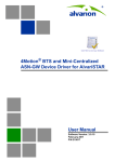
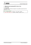
Figure 1-2 show the basic mobile WiMAX network architecture, with a single ASN-GW and with
multiple ASN-GWs, as defined by the WiMAX Forum NWG.
Figure 1-1: Mobile WiMAX Network Reference Model
Figure 1-2: ASN Reference Model containing Multiple ASN-GWs
The various components and entities involved in the networking architecture are:
BreezeMAX Mini-Centralized ASN-GW System Manual
3
Chapter 1 - System Description
1.2.1
WiMAX Network Reference Model
Access Service Network (ASN)
An ASN is defined as a complete set of network functions needed to provide radio access to a WiMAX
subscriber. The ASN provides the following mandatory functions:
WiMAX Layer-2 (L2) connectivity with WiMAX mobile station (MS)
Transfer of AAA messages to the WiMAX subscriber's home network service provider (H-NSP) for
authentication, authorization and session accounting for subscriber sessions
Network discovery and selection of the WiMAX subscriber's preferred NSP
Relay functionality for establishing Layer-3 (L3) connectivity with a WiMAX MS (i.e. IP address
allocation)
Radio resource management
ASN-CSN tunneling
ASN anchored mobility
An ASN is comprised of network elements such as one or more base transceiver stations and one or
more ASN gateways. An ASN may be shared by more than one connectivity service network (CSN).
1.2.2
Connectivity Service Network (CSN)
A CSN is defined as a set of network functions that provide IP connectivity services to WiMAX
subscribers. A CSN may offer the following functions:
MS IP address and endpoint parameter allocation for user sessions
Internet access
AAA proxy or server
Policy and admission control based on user subscription profiles
ASN-CSN tunneling support
WiMAX subscriber billing and inter-operator settlement
WiMAX services such as location-based services, connectivity for peer-to-peer services, provisioning,
authorization and/or connectivity to IP multimedia services, and facilities to support lawful intercept
services such as those compliant with Communications Assistance Law Enforcement Act (CALEA)
procedures
A CSN is comprised of network elements such as routers, proxy/servers, user databases, and
inter-working gateway devices.
1.2.3
Network Access Provider (NAP)
An NAP is a business entity that provides WiMAX radio access infrastructure to one or more WiMAX
network service providers (NSPs). A NAP implements this infrastructure using one or more ASNs.
BreezeMAX Mini-Centralized ASN-GW System Manual
4
Chapter 1 - System Description
1.2.4
WiMAX Network Reference Model
Network Service Provider (NSP)
An NSP is a business entity that provides IP connectivity and WiMAX services to WiMAX subscribers
compliant with the established service level agreement. The NSP concept is an extension of the Internet
service provider (ISP) concept, providing network services beyond Internet access. To provide these
services, an NSP establishes contractual agreements with one or more NAPs. An NSP may also establish
roaming agreements with other NSPs and contractual agreements with third-party application providers
(e.g. ASP, ISP) for the delivery of WiMAX services to subscribers. From a WiMAX subscriber standpoint,
an NSP may be classified as a home or visited NSP.
1.2.5
Base Station (BS)
The WiMAX BS is an entity that implements the WiMAX MAC and PHY in compliance with the IEEE
802.16e standard. A BS operates on one frequency assignment, and incorporates scheduler functions
for uplink and downlink resources.
The basic functionality of the BS includes:
IEEE 802.16e OFDMA PHY/MAC entity
R6 and R8 functionality according to NWG definitions
Extensible Authentication Protocol (EAP) relay
Control message authentication
User traffic authentication and encryption
Handover management
QoS service flow management entity
1.2.6
ASN Gateway (ASN-GW)
The ASN-GW is a network entity that acts as a gateway between the ASN and CSN. The ASN functions
hosted in an ASN-GW may be viewed as consisting of two groups - the decision point (DP) and
enforcement point (EP). The EP includes bearer plane functions, and the DP includes non-bearer plane
functions.
The basic DP functionality of the ASN-GW includes:
Implementation of EAP Authenticator and AAA client
Termination of RADIUS protocol against the selected CSN AAA server (home or visited AAA server) for
MS authentication and per-MS policy profile retrieval
Storage of the MS policy profile
Generation of authentication key material
QoS service flow authorization entity
AAA accounting client
BreezeMAX Mini-Centralized ASN-GW System Manual
5
Chapter 1 - System Description
WiMAX Network Reference Model
The basic EP functionality of the ASN-GW includes:
Classification of downlink data into generic routing encapsulation (GRE) tunnels
Packet header suppression functionality
DHCP functionality
Handover functionality
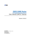
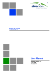
The WIMAX Forum NWG has adopted two different approaches for ASN architecture - centralized and
distributed: In the centralized approach there is at least one central ASN-GW, and the NPU operates in
transparent mode, as shown in Figure 1-3.
Figure 1-3: Centralized Network Reference Model
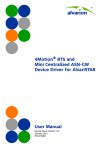
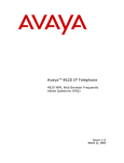
In the distributed approach, the NPU (Network Processing Unit) of the BTS operates in ASN-GW mode,
as shown in Figure 1-4.
BreezeMAX Mini-Centralized ASN-GW System Manual
6
Chapter 1 - System Description
WiMAX Network Reference Model
Figure 1-4: Distributed Network Reference Model
Alvarion believes in providing operators with the flexibility to select the mobile WiMAX network
topology that best suits their needs and existing network architecture. Therefore, its WiMAX solutions
are designed to support both distributed and centralized topology approaches according to WiMAX
Forum NWG profile C.
1.2.7
Reference Points
Reference point R1 consists of the protocols and procedures between the MS and ASN as per the
air-interface (PHY and MAC) specifications (IEEE 802.16e).
Reference point R2 consists of protocols and procedures between the MS and CSN associated with
authentication, services authorization and IP host configuration management. This reference point is
logical in that it does not reflect a direct protocol interface between the MS and CSN. The
authentication part of reference point R2 runs between the MS and CSN operated by the home NSP,
however, the ASN and CSN operated by the visited NSP may partially process the aforementioned
procedures and mechanisms. Reference point R2 might support IP host configuration management
running between the MS and CSN (operated by either the home NSP or visited NSP).
Reference point R3 consists of the set of control plane protocols between the ASN and CSN to
support AAA, policy enforcement and mobility management capabilities. It also encompasses the
bearer plane methods (e.g. tunneling) to transfer user data between the ASN and CSN.
Reference point R4 consists of the set of control and bearer plane protocols originating/terminating
in various functional entities of an ASN that coordinate MS mobility between ASNs and ASN-GWs. R4
is the only interoperable reference point between similar or heterogeneous ASNs.
BreezeMAX Mini-Centralized ASN-GW System Manual
7
Chapter 1 - System Description
WiMAX Network Reference Model
Reference point R5 consists of the set of control plane and bearer plane protocols for
internetworking between the CSN operated by the home NSP and that operated by a visited NSP.
Reference point R6 consists of the set of control and bearer plane protocols for communication
between the BS and ASN-GW. The bearer plane consists of an intra-ASN data path between the BS
and ASN gateway. The control plane includes protocols for data path establishment, modification and
release control in accordance with the MS mobility events.
Reference point R8 consists of the set of control plane message flows and optional bearer plane
data flows between the base stations to ensure a fast and seamless handover. The bearer plane
consists of protocols that allow data transfer between base stations involved in the handover of a
certain MS.
It is important to note that all reference points are logical and do not necessarily imply a physical or even
direct connection. For instance, the R4 reference point between ASN-GWs might be implemented across
the NAP internal transport IP network, in which case R4 traffic might traverse several routers from the
source to the destination ASN-GW.
BreezeMAX Mini-Centralized ASN-GW System Manual
8
Chapter 1 - System Description
1.3
The Mini-Centralized ASN-GW
The Mini-Centralized ASN-GW
The Mini-Centralized ASN-GW provides ASN-GW functions in a small package, simplifying
implementation of various deployment scenarios where a single ASN-GW serves several BTSs.
Specifically, it targets high speed transport locations, which wouldn't normally host BTSs, allowing
optimal, flexible, and scalable network design, significantly raising traffic bandwidth and reducing
CAPEX and OPEX. The Mini-Centralized ASN-GW may complement both indoor and outdoor BTS
systems (i.e.BreezeMAX 4Motion Indoor and Outdoor systems and BreezeMAX Extreme systems), while
operating concurrently with integrated ASN-GW instances.
The Mini-Centralized ASN-GW supports stackable solution with additional features such as load
balancing and various redundancy configurations.
The main functions of the Mini-Centralized ASN-GW are:
Connectivity Functions:
»
Traffic VLAN encapsulation
»
QoS marking
»
Local and remote extensive management support via CLI (Telnet, SSH) and SNMP, including
software download, fault and performance management
»
Security functionalities such as rate limiting and access control lists
»
Connection to a cascaded unit (future feature)
BreezeMAX Mini-Centralized ASN-GW System Manual
9
Chapter 1 - System Description
The Mini-Centralized ASN-GW
ASN-GW Functions:
»
EAP authenticator
»
RADIUS AAA client
»
AAA accounting client
»
MS policy profile storage
»
QoS service flow authorization
»
Classification of downlink data into service flows
»
Packet header suppression functionality
»
Multiple service provider support (multihost) for improved security and wholesale model
»
DHCP functionality - internal server, DHCP proxy, DHCP relay (with Option 82 support)
»
Handover functionality
»
GRE encapsulation/decapsulation
»
IP-in-IP encapsulation/decapsulation
»
Transparent VLAN (single tag) and QinQ (dual tag) encapsulation
»
Fragmentation/reassembly
»
R6/R3 interfaces implementation
»
Keep-alive signaling towards the relevant BSs for enhanced management of service availability
The Mini-Centralized ASN-GW is supplied with a built-in license for up to 500 registered subscribers.
Using add-as-you-grow license-based pricing model, the number of registered subscribers can be
increased in increments of 500 up to a total of 3000 registered subscribers per unit. The unit can support
an aggregate throughput of up to 200 Mbps.
An SNMP agent in the unit implements proprietary MIBs for remote setting of operational modes and
parameters. Security features incorporated in the equipment restrict the access for management
purposes. The Mini-Centralized ASN-GW can be managed by AlvariSTAR Element Management System
(EMS) used for managing the BTS equipment of the system, providing the network Operation,
Administration and Maintenance (OA&M) staff and managers with all the network surveillance,
monitoring and configuration and service provisioning capabilities required to effectively manage the
network while keeping the resources and expenses at a minimum.
BreezeMAX Mini-Centralized ASN-GW System Manual
10
Chapter 1 - System Description
Specifications
1.4
Specifications
1.4.1
Data Communication (Ethernet Interfaces)
Table 1-1: Data Communication (Ethernet Interfaces)
1.4.2
Item
Description
Standard Compliance
IEEE 802.3 CSMA/CD
Speed &
Duplex
Data Port
10/100/1000 Mbps, Full Duplex with Auto Negotiation
Management Port
10/100 Mbps, Half/Full Duplex with Auto Negotiation
Cascade Port
10/100/1000 Mbps, Full Duplex with Auto Negotiation
Configuration and Management
Table 1-2: Configuration and Management
Item
Description
Out Of Band (OOB) Management
Telnet via Management port
SSH via Management port
SNMP via Management port
Telnet via Cascade port
SSH via Cascade port
SNMP via Cascade port
Monitor port (serial interface)
In Band (IB) Management via Data Port
SNMP
Telnet
SSH
SNMP Agents
SNMP ver 2 client
MIB II (RFC 1213), Private MIBs
Software Upgrade
Using TFTP
Configuration Upload/Download
Using TFTP
BreezeMAX Mini-Centralized ASN-GW System Manual
11
Chapter 1 - System Description
1.4.3
Specifications
Standards Compliance, General
Table 1-3: Standards Compliance, General
Type
Standard
EMC
ETSI EN 301 489-1/4
FCC Part 15
EN60950-1
Safety
UL 60950-1
Lightning Protection
EN61000-4-5
Environmental
ETS 300 019,
Part 2-1 T 1.2
Part 2-2 T 2.3
Part 2-3 T 3.2
1.4.4
Environmental
Table 1-4: Environmental Specifications
Type
Details
Operating Temperature
-5°C to 50°C
Operating Humidity
5%-95%
BreezeMAX Mini-Centralized ASN-GW System Manual
12
Chapter 1 - System Description
1.4.5
Specifications
Mechanical and Electrical
Table 1-5: Mechanical & Electrical Specifications
Item
Description
Dimensions
1U high ETSI type shelf, 1U x 43.2 x 45 cm
Weight
3.4 Kg
Power Source
-36 to -60 VDC, typical -48 VDC
Power Consumption
100W maximum
BreezeMAX Mini-Centralized ASN-GW System Manual
13
Chapter 2 - Commissioning
In This Chapter:
“Initial Unit Configuration” on page 15
“Completing the Configuration Using AlvariSTAR” on page 18
Chapter 2 - Commissioning
2.1
Initial Unit Configuration
2.1.1
Introduction
Initial Unit Configuration
After completing the installation process, some basic parameters must be configured locally using the
CLI via the MON port of the unit.
Refer to “Using the Command Line Interface (CLI)” on page 23 for information on how to access the CLI
either via the MON port or via Telnet and how to use it.
The following sections describe the minimum mandatory configuration actions required to allow remote
configuration of the site and to enable discovery by the EMS system:
1 Clearing Previous Configuration
2 Site Connectivity
3 Static Route Definition
4 SNMP Manager and Trap Manager Definition
5 Site ID Definition
6 Saving the Configuration
2.1.2
Clearing Previous Configuration
Clear existing site configuration (must be executed for "used” units). Restore to factory default and
reboot using the following command:
npu# restore-factory-default
The system will reset automatically.
2.1.3
Site Connectivity
2.1.3.1
Connectivity Mode
The connectivity mode determines how traffic is to be routed between the unit and external servers
(AAA server and Management System servers).
The default connectivity mode is In-Band (IB). Alternatively, the unit can be managed Out-Of-Band (OOB)
or Unified Connectivity Mode.
To view the current and configured connectivity mode, use the command:
npu# show connectivity mode
To change the connectivity mode to Out-Of-Band, use the command:
npu(config)# connectivity mode outband.
BreezeMAX Mini-Centralized ASN-GW System Manual
15
Chapter 2 - Commissioning
Initial Unit Configuration
To change the connectivity mode to Unified, use the command:
npu(config)# connectivity mode unified.
For details refer to “Configuring the IP Connectivity Mode” on page 53.
2.1.3.2
VLANs Translation (Inband Connectivity Mode)
The Data port operates in VLAN-aware bridging mode (tagged-trunk mode). The values configured for
VLAN ID(s) used on this port are the VLAN IDs used internally. These are the VLAN ID for the bearer IP
interface (the default is 11) and, in In-Band Connectivity mode, the VLAN ID of the
external-management IP interface (the default is 12).
When using In-Band connectivity via the Data port, if the value of the VLAN ID used for management in
the backbone differs from the value configured for the external-management interface, the
external-management VLAN ID should be translated accordingly. It is recommended to configure also
VLAN translation for the bearer interface.
To enable VLAN translation and configure the required VLANs translation, run the following commands
(the examples are for backhaul Data VLAN ID 30 and Management VLAN ID 31, assuming the default
VLAN IDs for external-management and bearer interfaces):
1 Enable the Data port configuration mode (for details refer to “Enabling the Interface configuration
mode” on page 56):
npu(config)# interface gigabitethernet 0/10
2 Enable VLAN translation (for details refer to “Enabling/Disabling VLAN Translation” on page 63):
npu(config-if)# vlan mapping enable
3 Translate management VLAN 12 to the backhaul management VLAN 31: npu(config-if)# vlan
mapping 12 31 (for details refer to “Creating a VLAN Translation Entry” on page 63)
4 Translate data VLAN 11 to the backhaul data VLAN 30:
npu(config-if)# vlan mapping 11 30
5 Exit the interface configuration mode: npu(config-if)# exit
To view the VLAN mapping parameters, run the command:
npu# show interface gigabitethernet 0/10 vlan mapping.
2.1.3.3
External Management Interface
To configure the necessary parameters of the External Management interface used for connectivity with
the EMS system, run the following commands:
1 Enable the External Management interface configuration mode (for details refer to “Enabling the
Interface configuration mode” on page 56):
npu(config)# interface external-mgmt
(there is no need to shut down the interface for configuring its parameters)
BreezeMAX Mini-Centralized ASN-GW System Manual
16
Chapter 2 - Commissioning
Initial Unit Configuration
2 Configure the IP address (x.x.x.x) and subnet mask (y.y.y.y). For details refer to “Assigning an IP
address to an interface” on page 71:
npu(config-if)# ip address x.x.x.x y.y.y.y
3 Exit the interface configuration mode: npu(config-if)# exit
4 Exit the configuration mode: npu(config)# exit
2.1.3.4
Save and Apply Changes in Site Connectivity Configuration
1 Save the configuration: npu# write (otherwise, after the next time reset you will lose the
configuration changes).
2 If you changed the Connectivity Mode, reset the system to apply the changes: npu# reset
2.1.4
Static Route Definition
Static Route must be configured whenever the EMS server and the managed unit are on different
subnets. For more details refer to “Adding a Static Route” on page 111.
Run the following command: npu(config)# "ip route x.x.x.x y.y.y.y z.z.z.z"
(x.x.x.x is the IP address of the EMS server, y.y.y.y is the network mask of the EMS server, z.z.z.z is the
next-hop IP address that should be in the segment of the external-management interface.
2.1.5
SNMP Manager and Trap Manager Definition
To define the communities to be used by the SNMP manager, run the command:
npu(config)# snmp-mgr ReadCommunity public ReadWriteCommunity private.
For more details refer to “Adding an SNMP Manager” on page 324.
For proper operation of the manager you should configure also the Trap Manager parameters and
enable sending traps to the defined Trap Manager (this can also be done later via the management
system):
1 npu(config)# trap-mgr ip-source x.x.x.x port 162 TrapCommunity public
(x.x.x.x is the IP address of the EMS server). For more details refer to “Adding/Modifying a Trap
Manager Entry” on page 327
2 npu(config)# trap-mgr enable ip-source x.x.x.x
Note that if the management system is behind a NAT router, the NAT Outside IP address (the IP of the
router’s interface connected in the direction of the managed device LAN) must be defined in the device
as a Trap Manager, with traps sending enabled. In the NAT router, Port Forwarding (NAT Traversal) must
be configured for UDP and TCP ports 161 and 162 from Outside IP (connected to the managed device’s
LAN) to Inside IP (connected to the management system’s LAN).
BreezeMAX Mini-Centralized ASN-GW System Manual
17
Chapter 2 - Commissioning
2.1.6
Completing the Configuration Using AlvariSTAR
Site ID Definition
To define the site ID (Site Number): npu(config)# site identifier x
(x is the unique site identifier, a number in the range from 1 to 999999)
For more details refer to “Configuring the Unique Identifier” on page 340.
2.1.7
Saving the Configuration
To save the configuration run the command: npu# write (otherwise, after the next time reset you will
lose the configuration changes).
2.2
Completing the Configuration Using AlvariSTAR
After completion of the initial configuration you should be able to manage the unit using AlvariSTAR,
and continue configuring necessary parameters to enable the necessary services.
For details on how to use AlvariSTAR for managing the unit refer to the AlvariSTAR and Device Manager
User Manuals.
Verify that the unit is included in the list of devices that can be managed by AlvariSTAR. It can be added
to the list of managed devices either through the Equipment Manager (by creating a New managed
device) or through the Task Manager using either Network Discovery Task or Range Discovery Task.
INFORMATION
The site’s configuration can also be completed using a pre-prepared file. For details refer to the Offline
Configuration Tool or Duplicate Site sections in the Device Manager User Manual.
To complete the minimal configuration, open the Site’s Device Manager from the Equipment Manager
and perform the following configuration steps:
Connectivity Configuration
Equipment Configuration - GPS
ASNGW Configuration
2.2.1
Connectivity Configuration
2.2.1.1
Connectivity - ASN-GW Bearer Interface Page
Configure the IP parameters of the Bearer interface:
1 Change the Source IP Address, Subnet Mask and Default Gateway.
2 Click on Apply to accept the changes.
BreezeMAX Mini-Centralized ASN-GW System Manual
18
Chapter 2 - Commissioning
2.2.1.2
Completing the Configuration Using AlvariSTAR
Connectivity - Management Page, Management Interface Tab
To support proper automatic management of IP Routes for Trap Managers, TFTP Servers and SNTP
Servers the External Management Next Hop Gateway must be defined (not applicable in Unified
Connectivity Mode).
1 If applicable, configure the External Management Next Hop Gateway.
2 Click on Apply to accept the change.
2.2.2
Equipment Configuration - GPS
In the Navigation pane, select the Equipment - External - GPS option.
The default GPS Type (synchronization source) is None. If SNTP is used, the SNTP option should be
selected. Configure also the IP address of the Primary Server and (if applicable) the IP address of the
Secondary Server.
If necessary, configure the Time Zone Offset From UTC and the Daylight Saving parameters.
Click Apply for the device to accept the changes.
2.2.3
ASNGW Configuration
2.2.3.1
AAA Page
1 Configure the following mandatory parameters:
»
Primary Server IP Address
»
RADIUS Shared Secret (the same Shared Secret should also be defined in the AAA server)
»
ASNGW NAS ID
2 Click Apply for the device to accept the configuration.
2.2.3.2
Service Group Page
2.2.3.2.1
Service Interfaces Tab
At least one Service Interface for data must be defined. If a dedicated management station for CPEs is
being used, a suitable Service Interface for management must also be defined. A Service Interface must
be defined before configuring a Service Group associated with it.
BreezeMAX Mini-Centralized ASN-GW System Manual
19
Chapter 2 - Commissioning
Completing the Configuration Using AlvariSTAR
1 Click on the Add Service Interface button and configure the following mandatory parameters:
»
Service Interface Name
»
Type
»
Tunnel Destination IP (IP-in-IP Service Interface)
»
Service VLAN ID (VLAN or QinQ Service Interface)
»
Default Gateway IP Address (VLAN Service Interface)
2 Click Apply for the device to accept the configuration.
2.2.3.2.2
Service Groups Tab
At least one Service Group associated with a defined Service Interface for data must be defined. If a
dedicated management station for CPEs is being used, a suitable Service Group associated with the
defined Service Interface for management must also be defined.
1 Click on the Add Service Group button and configure at least the following mandatory parameters:
»
Name
»
Type
»
Service Interface Name
»
DHCP Function Mode
»
DHCP Own IP Address
»
External DHCP Server IP Address (Relay mode)
»
IP Address Pool From (Server mode)
»
IP Address Pool To (Server mode)
»
Subnet Mask (Server mode)
»
DNS Server IP Address (Proxy mode)
2 Click Apply for the device to accept the configuration.
2.2.3.3
SFA Page -Classification Rules Tab
This page is not applicable if Service Profiles, Service Flows and Classification Rules are defined in the
AAA Server.
Create the necessary Classification Rule(s) according to the relevant type of traffic, and click Apply.
BreezeMAX Mini-Centralized ASN-GW System Manual
20
Chapter 2 - Commissioning
2.2.3.4
Completing the Configuration Using AlvariSTAR
Service Profiles
Configuration of Service Profiles is not applicable if Service Profiles, Service Flows and Classification Rules
are defined in the AAA Server. Otherwise, at least one Service Profile must be defined and associated
with an already defined Service Group.
1 Right-click on the Service Profile node and select Create. The New Service Profile window is
displayed.
2 Define the Name of the New Service Profile and click Apply.
3 The new Service Profile added to the list of available Service Profiles in the navigation tree. Select it to
continue the configuration process.
4 Click Add in the Service Flow area.
5 Configure the applicable general parameters of the Service Flow.
6 Configure the applicable QoS parameters of Service Flow for UL and DL (for example, for Data
delivery type=BE it will be Maximum Sustained Traffic Rate and Traffic Priority).
7 Associate this Service Flow with previously created Classification Rule(s).
8 Change the Profile Status to Enable
9 Click Apply for the device to accept the configuration.
BreezeMAX Mini-Centralized ASN-GW System Manual
21
Chapter 3 - Operation and
Administration Using the CLI
In This Chapter:
“Using the Command Line Interface (CLI)” on page 23
“Shutting Down/Resetting the System” on page 48
“Unit Configuration” on page 51
“Managing MS in ASN-GW” on page 343
“Monitoring Hardware and Software Performance” on page 347
Chapter 3 - Operation and Administration Using the CLI
3.1
Using the Command Line Interface (CLI)
Using the Command Line Interface (CLI)
The following system management options using CLI are available:
Accessing the Command Line Interface (CLI) locally via the MON port
Using Telnet/Secure Shell (SSH) to access the CLI
The CLI is a configuration and management tool that you can use to configure and operate the unit,
either locally or remotely, via Telnet/SSH. The following are some administrative procedures to be
executed using the CLI:
Selecting the connectivity mode
Shutting down/resetting the unit
Configuring and operating the unit
Monitoring hardware and software components
Executing debug procedures
Executing software upgrade procedures
This section provides information about:
“Accessing the CLI” on page 23
“Command Modes” on page 26
“Interpreting the Command Syntax” on page 27
“Using the CLI” on page 28
“Managing Users and Privileges” on page 31
“Managing Secure Shell (SSH) Parameters” on page 40
“Managing the Session” on page 42
3.1.1
Accessing the CLI
You can access the CLI, locally, via an ANSI ASCII terminal or PC that is connected via the Monitor (MON)
port. You can also use Telnet/SSH to remotely access the CLI.
This section describes the procedures for:
“Accessing the CLI from a Local Terminal” on page 24
“Accessing the CLI From a Remote Terminal” on page 24
BreezeMAX Mini-Centralized ASN-GW System Manual
23
Chapter 3 - Operation and Administration Using the CLI
3.1.1.1
Using the Command Line Interface (CLI)
Accessing the CLI from a Local Terminal
To access the CLI via the MON connector:
1 Use the MON cable to connect the MON connector of the unit to the COM port of your ASCII ANSI
terminal or PC. The COM port connector of the Monitor cable is a 3-pin to 9-pin D-type plug.
2 Run a terminal emulation program, such as HyperTerminal™.
3 Set the communication parameters listed in the following table:
Table 3-1: COM Port Configuration
Parameter
Value
Baud rate
115200
Data bits
8
Stop bits
1
Parity
None
Flow control
Xon/Xoff
Port
Connected COM port
4 The login prompt is displayed. (Press Enter if the login prompt is not displayed.) Enter your login ID
and password to log in to the CLI.
INFORMATION
The default login ID and password for administrator privileges are:
Login ID: admin
Password: admin123
After you provide your login information, the following command prompt is displayed:
npu#
This is the global command mode. For more information about different command modes, refer to
Section 3.1.2.
3.1.1.2
Accessing the CLI From a Remote Terminal
The procedure for accessing the CLI from a remote terminal differs with respect to the IP connectivity
mode. The Ethernet port and IP interface you are required to configure for enabling remote connectivity
is different for each connectivity mode. For more information about connectivity modes, and Ethernet
ports and IP interface used for operating the system, refer “Managing the IP Connectivity Mode” on
page 51.
BreezeMAX Mini-Centralized ASN-GW System Manual
24
Chapter 3 - Operation and Administration Using the CLI
Using the Command Line Interface (CLI)
To access the CLI from a remote terminal, execute the following procedure:
NOTE!
The in-band connectivity mode is the default connectivity mode; the DATA port and
external-management VLAN are the default Ethernet port and IP interface that are configured for the
in-band connectivity mode. The following procedure can be used for accessing the CLI when the
in-band connectivity mode is selected. This procedure is identical for all other connectivity modes.
However, the Ethernet port, VLAN, and IP interface to be configured will differ for the out-of-band and
unified connectivity modes, as listed in Table 3-8.
1 Assign an IP address to the external-management interface. For this, execute the following
procedure. (Refer Table 3-8 for more information about the IP interface to be configured for the
connectivity mode you have selected).
a Run the following command to enable the interface connectivity mode for the
external-management interface:
npu(config)# interface external-mgmt
b Run the following command to assign an IP address to this interface:
npu(config-if)# ip address <ip-address> <subnet-mask>
2 Connect the Ethernet cable to the DATA connector on the front panel of the unit. (Refer Table 3-8 for
more information about the Ethernet port to be used for the connectivity mode you have selected).
3 To enable exchange of packets, create IP-level connectivity between the remote machine and the
external-management interface. Typically, the DATA port should be connected to a switch port
operating in trunk mode, and the remote machine is connected to another port of the same switch
that is configured to operate in access mode with the external-management VLAN ID (default is 12).
4 From the remote terminal, execute the following command to use Telnet/SSH to access the IP address
of the external-management interface:
telnet <ip address of external-management interface>
ssh <ip address of external-management interface>
Refer to “Managing Secure Shell (SSH) Parameters” on page 40 for details on managing SSH
parameter.
5 At the prompt, enter your login ID and password.
INFORMATION
The default login ID and password for administrator privileges are:
Login ID: admin
Password: admin123
BreezeMAX Mini-Centralized ASN-GW System Manual
25
Chapter 3 - Operation and Administration Using the CLI
Using the Command Line Interface (CLI)
After you provide your login information, the following command prompt is displayed:
npu#
This is the global command mode. For more information about different command modes, refer to
Section 3.1.2.
3.1.2
Command Modes
The CLI provides a number of command modes, some of which are listed in the following table for
executing different types of commands:
Table 3-2: CLI Command Modes
Mode
Used for...
Command Prompt
Global configuration mode
Executing configuration
commands
npu(config)#
Global command mode
Executing all other commands
such as show commands and
some general unit management
commands
npu#
Interface configuration mode
Executing all commands for
configuring physical and IP
interfaces.
npu(config-if)#
Standard/extended ACL mode
Executing commands for
configuring standard and
extended ACLs
npu(config-std-nacl)#
npu(config-ext-nacl)#
The following table lists the commands to be executed for entering/exiting a particular command mode:
Table 3-3: Commands to Enter/Exit a Command Mode
To...
Run the Command...
The Command Mode is
Now...
Enter the global configuration
mode
npu# config terminal
npu(config)#
Enter the interface
configuration mode
npu(config)# interface
{<interface-type>
<interface-id>
|external-mgmt | bearer
| local-mgmt |
npu-host}
npu(config-if)#
BreezeMAX Mini-Centralized ASN-GW System Manual
26
Chapter 3 - Operation and Administration Using the CLI
Using the Command Line Interface (CLI)
Table 3-3: Commands to Enter/Exit a Command Mode
3.1.3
Exit the configuration mode and
enter the global command
mode.
npu(config)# end
npu#
npu (config-if)# end
npu#
Exit the current configuration
mode by one level
npu (config-if)# exit
npu(config)#
Interpreting the Command Syntax
The following table lists the conventions used in the command syntax for all commands:
Table 3-4: Conventions Used in the Command Syntax
Convention
Description
Example
{}
Indicates that the parameters
enclosed in these brackets are
mandatory, and only one of these
parameters should be specified.
npu(config)# limit {cpu |
memory} ([softlimit <limit>]
[hardlimit <limit>])
Indicates that one or all
parameters enclosed within these
brackets are optional. However,
the presence of at least one
parameter is required to
successfully execute this
command.
npu(config)# limit {cpu |
memory} ([softlimit <limit>]
[hardlimit <limit>])
Indicates that the parameter
enclosed within these brackets is
optional.
npu(config)# reboot from shadow
[<shadow image name>]
()
[]
BreezeMAX Mini-Centralized ASN-GW System Manual
This command is used for specifying the soft
and hard limits for memory and CPU
utilization. The cpu/memory parameters are
enclosed within {} brackets, indicating that
their presence is mandatory, and that only
one of these parameters is required.
This command is used for specifying the soft
and hard limits for memory and CPU
utilization. The softlimit and hardlimit
parameters are enclosed within () brackets,
indicating that you are required to specify
the value of at least one of these parameters
to successfully execute this command.
This command is used to reboot the system
with the shadow image. The shadow image
name parameter is enclosed with the [ ]
brackets, indicating that it is optional. If you
do not specify the value of this parameter,
the system automatically boots up with the
last downloaded shadow image.
27
Chapter 3 - Operation and Administration Using the CLI
Using the Command Line Interface (CLI)
Table 3-4: Conventions Used in the Command Syntax
Convention
Description
Example
<>
Indicates that the parameter is
mandatory and requires a
user-defined value (and not a
discrete value).
npu(config)# load to shadow
<shadow image name>
Indicates the OR conditional
operator that is used between two
or more parameters. The presence
of this parameter indicates that
only one of the parameters
separated by the I conditional
parameter should be specified in
the command.
npu(config)# pm-group enable npu
{R6InterfaceTotal |
R6InterfaceBs | ProvisionedQOS |
R3Interface | InitialNe |
ServiceFlow}
|
This command is used to load the system
with a particular shadow image. It is
mandatory to specify a value for the shadow
image name parameter; otherwise an error is
raised by the system. The value of this
parameter is not a discrete value; you are
required to specify a value for this parameter.
This command is used to specify the group
for which performance data collection and
storage is to be enabled. The | conditional
operator indicates that only one parameter
should be specified.
INFORMATION
In this document, all discrete values are specified in boldface, and all user-defined values are not bold.
3.1.4
Using the CLI
To help you use the CLI, this section provides information about:
“Using Control Characters” on page 28
“Using the CLI Help” on page 29
“Using the History Feature” on page 29
“Using Miscellaneous Commands” on page 30
“Privilege Levels” on page 30
3.1.4.1
Using Control Characters
Control characters refer to special characters that you can use to recall or modify previously-executed
commands. The following table lists the control characters to be used for executing commands on the
CLI:
BreezeMAX Mini-Centralized ASN-GW System Manual
28
Chapter 3 - Operation and Administration Using the CLI
Using the Command Line Interface (CLI)
Table 3-5: Control Characters for Using the CLI
3.1.4.2
Press
To...
Up/Down arrow keys
Scroll the previously executed CLI commands.
Press Enter if you want to select and execute a
particular command.
Right/Left arrow keys
Navigate to the right/left of the selected character
in a command.
Home key
Navigate to the first character of a command.
End key
Navigate to the last character of a command.
Backspace key
Delete the characters of a command.
TAB key
Prompt the CLI to complete the command for
which you have specified a token command.
Remember that the CLI that is the nearest match
to the token command that you have specified is
displayed.
? key
View the list of commands available in the current
mode. If you press ? after a command, a list of
parameters available for that command is
displayed.
Using the CLI Help
The CLI provides help that you can access while using the CLI. Execute the following command to obtain
help for a specific command:
help [“<text>”]
Specify the command name as the parameter to view help for this command. For example, to obtain
help for the show resource limits command, run the following command:
npu# help “show resource limits”
The help for the show resource limits command is displayed.
If you do not provide the command name as the parameter, all commands that can be executed in the
current command mode are displayed.
3.1.4.3
Using the History Feature
The history feature of the CLI maintains a sequential list of all previously executed commands. The
following table lists the commands that you can run to access, edit or execute a command from the
command history list:
BreezeMAX Mini-Centralized ASN-GW System Manual
29
Chapter 3 - Operation and Administration Using the CLI
Using the Command Line Interface (CLI)
Table 3-6: Commands for Using the History Feature
3.1.4.4
Run the command...
To...
show history
Obtain a list of previously executed commands (up to 14).
!!
Execute the last command displayed in the list of previously executed
commands.
!<n>
Execute the nth command in the list of previously-executed commands.
!<string>
Execute the most recent command in the CLI history that starts with the
string entered as the value for the string parameter.
Using Miscellaneous Commands
The following table lists other miscellaneous commands that you can execute in any mode using any
privilege level:
Table 3-7: Miscellaneous Commands
3.1.4.5
Enter the command...
To...
exit
Exit the current configuration mode. In global command mode this
command will cause termination of the session.
clear screen
Clear the screen.
Privilege Levels
All commands that can be executed using the CLI are assigned privilege levels between 0 and 15, where
0 is the lowest, and 15 is the highest. In addition, each user is assigned a privilege level; the user can
access only those commands for which the privilege level is the same or lower than the user’s privilege
level.
The system is supplied with the following default users:
Maximum privilege user (default user name is root) with privilege level 15. The root user is reserved
for the vendor. Privilege level 15 enables executing all commands, including commands associated
with configuration of vendor parameters.
Administrator user (default user is admin, default password is admin123) with privilege level 10.
Privilege level 10 enables executing all commands, excluding commands associated with
configuration of vendor parameters.
BreezeMAX Mini-Centralized ASN-GW System Manual
30
Chapter 3 - Operation and Administration Using the CLI
Using the Command Line Interface (CLI)
Guest user (default user name is guest, default password is guest123) with privilege level 1. Privilege
level 1 enables executing a minimal set of general commands and viewing configuration details
through the “show” commands. The EXEC commands available for users with privilege level 1 are:
»
clear screen
»
disable [<0-15> Privilege level to go to]
»
enable [<0-15> Enable Level]
»
exit
»
help [ command ]
»
logout
»
ping <ip-address> [timeout <seconds(1-15)>] [count <count(1-32767)>]
»
run script <script file> [<output file>]
In addition, any user can switch to privilege level 0 (no user name). This privilege level allows
maintaining an open session while enabling (for security reasons) a very limited set of general
commands. The available EXEC commands are:
»
clear screen
»
enable [<0-15> Enable Level]
»
exit
»
help [ command ]
»
logout
»
show privilege
The default admin user can execute certain additional commands for managing users and enabling
passwords for privilege levels up to and including privilege level 10. Currently, all privilege levels between
2 to 9 provide functionality that is the same as privilege level 1. For more information about managing
users and privileges, refer to Section 3.1.5. Privilege levels above 10 are manageable only by the root
(vendor) user.
3.1.5
Managing Users and Privileges
To enable multi-level access to the CLI, you can create and manage multiple users, and assign privilege
levels for each user. The privilege level determines whether a user is authorized to execute a particular
command. The privilege level is pre-configured for each command, and can be between 1 and 10,
where 1 is the lowest and 10 is the highest. The user can execute all commands for which the privilege
level is equal to or lower than the default privilege level assigned to the user.
BreezeMAX Mini-Centralized ASN-GW System Manual
31
Chapter 3 - Operation and Administration Using the CLI
NOTE!
Using the Command Line Interface (CLI)
By default, the privilege level of users logging in with admin privileges is 10. However, the admin user
can execute some additional commands for adding users and enabling passwords for different privilege
levels.
You can also configure passwords for each privilege level. Users with lower privilege levels can enter this
password to enable higher privilege levels.
This section describes the commands for:
“Managing Users” on page 32
“Managing Privileges” on page 34
“Enabling/Disabling Higher Privilege Levels” on page 37
“Displaying Active Users” on page 39
“Displaying All Users” on page 39
“Displaying the Privilege Level” on page 40
3.1.5.1
Managing Users
You can add/modify/delete one or more users for accessing the CLI either through a local or remote
terminal.
NOTE!
Only users who have logged in as admin can add/modify/delete users.
This section describes the commands for:
“Adding/Modifying Users” on page 32
“Deleting a User” on page 33
3.1.5.1.1
Adding/Modifying Users
NOTE!
Only users who have logged in as admin can execute this task.
To add/modify a user, and assign a username, password, and privilege level, run the following command:
npu(config)# username <user-name> password <passwd> privilege <1-15>
BreezeMAX Mini-Centralized ASN-GW System Manual
32
Chapter 3 - Operation and Administration Using the CLI
NOTE!
Using the Command Line Interface (CLI)
An error may occur if:
You are not logged in as the admin.
The username or password that you have specified is more than 20 characters.
The privilege level that you have specified is not within the range, 1-10.
Command
Syntax
npu(config)# username <user-name> password <passwd> privilege <1-15>
Privilege
Level
10
Syntax
Descriptio
n
Command
Modes
3.1.5.1.2
Parameter
Description
Presence
Default
Value
Possible Values
username
<user-name>
Indicates the user name of the
user to be added.
Mandatory
N/A
String (up to 20
characters and
case-sensitive)
password
<passwd>
Indicates the password to be
assigned to the user to be
added.
Optional
password
String (up to 20
characters and
case-sensitive)
privilege
<1-10>
Indicates the privilege level to
be assigned to a user. The user
will be permitted to execute all
commands for which the
privilege level is equal to or
lower than the value of this
parameter.
Mandatory
N/A
1-15 (privilege
levels higher
than 10 are
available only
for root user)
Global configuration mode
Deleting a User
NOTE!
Only users who have logged in as admin can execute this task.
To delete a user, run the following command:
BreezeMAX Mini-Centralized ASN-GW System Manual
33
Chapter 3 - Operation and Administration Using the CLI
Using the Command Line Interface (CLI)
npu(config)# no user <username>
NOTE!
An error may occur if:
You are not logged in as admin user.
The username that you have specified does not exist. Remember that user names are case-sensitive.
You are trying to delete an active user or the admin user.
Command
Syntax
npu(config)# no user <username>
Privilege
Level
10
Syntax
Descriptio
n
Command
Modes
3.1.5.2
Parameter
Description
Presence
Default
Value
Possible Values
username
<name>
Indicates the username of the
user to be deleted.
Mandatory
N/A
String (up to 20
characters and
case-sensitive)
Global configuration mode
Managing Privileges
To enable users to execute commands that require a higher privilege level (than their currently
configured default level), you can configure a password for each privilege level. Other users can then use
the password you have specified to enable a higher privilege level.
NOTE!
Only users who have logged in as admin can assign or delete passwords for any privilege level.
This section describes the commands for:
“Assigning a Password for a Privilege Level” on page 35
“Deleting a Password for a Privilege Level” on page 36
BreezeMAX Mini-Centralized ASN-GW System Manual
34
Chapter 3 - Operation and Administration Using the CLI
3.1.5.2.1
Using the Command Line Interface (CLI)
Assigning a Password for a Privilege Level
NOTE!
Only users who have logged in as admin can execute this command.
To assign a password for a privilege level, run the following command:
npu(config)# enable password
[Level <1-15>] <LINE 'enable'password>
For example, run the following command to assign the password ten for
privilege level 10: npu(config)# enable password level 10 ten.
NOTE!
After you execute this command, any user can use this password to enable the (higher) privilege level for
which you have configured the password. For more information about using passwords for enabling
higher privilege levels, refer Section 3.1.5.3.
NOTE!
An error may occur if:
You are trying to configure a password for a privilege level that is higher than your default privilege
level (admin user can configure password for privilege levels up to 10).
The password that you have specified is more than 20 characters.
Command
Syntax
npu(config)# enable password
Privilege
Level
10
Syntax
Descriptio
n
[Level <1-15>] <LINE 'enable'password>
Parameter
Description
Presence
Default
Value
Possible Values
<1-15>
Indicates the privilege level for
which a password is to be
enabled.
Optional
10
1-10 (password
cannot be
defined for
privilege levels
higher than 10)
<password>
Denotes the password to be
assigned for the current
privilege level.
Mandatory
N/A
String (up to 20
characters and
case-sensitive)
BreezeMAX Mini-Centralized ASN-GW System Manual
35
Chapter 3 - Operation and Administration Using the CLI
Command
Modes
3.1.5.2.2
Using the Command Line Interface (CLI)
Global configuration mode
Deleting a Password for a Privilege Level
NOTE!
Only users who have logged in as admin can execute this command.
To delete a password for a privilege level, run the following command:
npu(config)# no enable password [Level <1-15>]
For example, to delete a previously assigned password for privilege level 10, run the command:
npu(config)# no enable password level 10
NOTE!
An error may occur if:
The privilege level that you have specified is not within the range, 1-10.
Command
Syntax
npu(config)# no enable password [Level <1-15>]
Privilege
Level
10
Syntax
Descriptio
n
Command
Syntax
Parameter
Description
Presence
Default
Value
Possible Values
<1-10>
Indicates the privilege level for
which a password is to be
disabled.
Optional
10
1-10 (password
cannot be
defined for
privilege levels
higher than 10)
Global configuration mode
BreezeMAX Mini-Centralized ASN-GW System Manual
36
Chapter 3 - Operation and Administration Using the CLI
3.1.5.3
Using the Command Line Interface (CLI)
Enabling/Disabling Higher Privilege Levels
You can execute commands that require higher privilege levels. If the admin user has configured a
password for that level (see “Assigning a Password for a Privilege Level” on page 35), you can use that
password to enable higher privilege levels.
For example, if your privilege level is 1, you can provide the password configured for privilege level 10 to
execute all commands that require privilege level 10.
This section describes the commands for:
“Enabling a Higher Privilege Level” on page 37
“Returning to the Default Privilege Level” on page 38
3.1.5.3.1
Enabling a Higher Privilege Level
To enable a higher privilege level:
1 Log in to the CLI.
2 Run the following command to specify the privilege level and password:
npu# enable [<0-15> Enable Level]
For example, if are logged in with privilege level 1 and you want to switch to privilege level 10 for
which a password has been assigned, run the command: npu# enable 10.
3 At the password prompt, specify the password configured for the privilege level that you have
specified.
If you specify the correct password, you are logged in to the CLI with the privilege level that you had
specified. You can now execute all commands that require the current privilege level.
INFORMATION
You can display your current privilege level, using the following command:
npu# show privilege
You can, at any time, return to your default privilege level. For details, refer Section 3.1.5.3.2.
INFORMATION
An error may occur if:
You have specified an incorrect password. Remember that all passwords are case-sensitive.
No password is configured for the privilege level you are trying to access.
Command
Syntax
npu# enable [<0-15> Enable Level]
BreezeMAX Mini-Centralized ASN-GW System Manual
37
Chapter 3 - Operation and Administration Using the CLI
Privilege
Level
Syntax
Descriptio
n
Command
Modes
INFORMATION
3.1.5.3.2
Using the Command Line Interface (CLI)
0
Parameter
Description
Presence
Default
Value
Possible Values
<0-15>
Indicates the privilege level you
want to enable.
Optional
10
0-15
Global configuration mode
The command npu# enable <0-15> can be used for switching to any privilege level, either higher or
lower than your current privilege level (including privilege level 0). A password is required only for
switching to a higher privilege level.
Returning to the Default Privilege Level
Run the following command to disable the current privilege level, and return to your default privilege
level:
npu# disable [<0-15>]
After you run this command, you automatically return to your default privilege level. You can display
your current privilege level, using the following command:
npu# show privilege
Command
Syntax
npu# disable [<0-15> Privilege level to go to]
Privilege
Level
1
BreezeMAX Mini-Centralized ASN-GW System Manual
38
Chapter 3 - Operation and Administration Using the CLI
Syntax
Descriptio
n
Using the Command Line Interface (CLI)
Parameter
Description
Presence
Default
Value
Possible Values
<0-15>
Indicates the privilege level you
want to witch to.
Optional
1
0-9
Must be lower than your
current privilege level.
Command
Modes
Global command mode
INFORMATION
The command npu# disable <0-15> can be used also for switching to any privilege level lower than your
current privilege level (including privilege level 0).
3.1.5.4
Displaying Active Users
To display all active users, run the following command:
npu# show users
Command
Syntax
npu# show users
Privilege
Level
1
Display
Format
Line
Command
Syntax
Global command mode
0 con
User
<user name>
Peer Address
<value>
Possible values for Line entry are con (console-via the MON port), tel (telnet) and ssh.
3.1.5.5
Displaying All Users
To display all users, run the following command:
BreezeMAX Mini-Centralized ASN-GW System Manual
39
Chapter 3 - Operation and Administration Using the CLI
Using the Command Line Interface (CLI)
npu# listuser
Command
Syntax
npu# listuser
Privilege
Level
1
Display
Format
User
Mode
User 1
<value>
User 2
<value>
User 3
<value>
Command
Syntax
3.1.5.6
Global command mode
Displaying the Privilege Level
To display your current privilege level, run the following command:
npu# show privilege
Command
Syntax
npu# show privilege
Privilege
Level
0
Display
Format
Current privilege level is <value>
Command
Syntax
Global command mode
3.1.6
Managing Secure Shell (SSH) Parameters
The SSH parameters define the parameters used for establishing remote secure access to the device
using SSH protocol rather than the plaintext-based insecure Telnet protocol.
BreezeMAX Mini-Centralized ASN-GW System Manual
40
Chapter 3 - Operation and Administration Using the CLI
Using the Command Line Interface (CLI)
This section includes:
“Configuring SSH Parameters” on page 41
“Restoring the Default Values of SSH Parameters” on page 42
“Displaying the SSH Parameters” on page 42
3.1.6.1
Configuring SSH Parameters
To configure SSH parameters, run the following command:
npu(config)# ip ssh {version compatibility | cipher ([des-cbc] [3des-cbc])
|
auth ([hmac-md5] [hmac-sha1]) }
Command
Syntax
npu(config)# ip ssh {version compatibility | cipher ([des-cbc] [3des-cbc])
| auth ([hmac-md5] [hmac-sha1]) }
Privilege
Level
10
Syntax
Descriptio
n
Parameter
Description
Presence
Default
Value
Possible Values
version
compatibility
The SSH version that can be
used: The default is SSH version
2.
Optional
SSH2
version
compatibility
des-cbc
des-cbc
Run the command
npu(config)# ip ssh version
compatibility to enable
compatibility with both SSH
version 1 and SSH version 2.
Command
Modes
cipher
([des-cbc]
[3des-cbc])
The encryption algorithm used
by the SSH protocol:
DES-CCBC or 3DES-CBC.
Optional
auth
([hmac-md5]
[hmac-sha1])
The authentication mechanism
used by the SSH protocol:
HMAC-MD5 or HMAC-SHA1.
OPtional
3des-cbc
hmac-sha
1
hmac-md5
hmac-sha1
Global configuration mode
BreezeMAX Mini-Centralized ASN-GW System Manual
41
Chapter 3 - Operation and Administration Using the CLI
3.1.6.2
Using the Command Line Interface (CLI)
Restoring the Default Values of SSH Parameters
To restore the default value of one or more SSH parameters, run the following command:
npu(config)# no ip ssh {version compatibility | cipher ([des-cbc]
[3des-cbc]) |
auth ([hmac-md5] [hmac-sha1]) }.
To restore the default values of all SSH parameters run the following command:
npu(config)# no ip ssh
Command
Syntax
npu(config)# no ip ssh {version compatibility | cipher ([des-cbc]
[3des-cbc]) | auth ([hmac-md5] [hmac-sha1]) }
Privilege
Level
10
Command
Modes
Global configuration mode
3.1.6.3
Displaying the SSH Parameters
To display the current configuration of the SSH parameters, run the following command:
npu# show ip ssh
Command
Syntax
npu# show ip ssh
Privilege
Level
1
Display
Format
Version
Cipher Algorithm : <value>
Authentication
Command
Modes
3.1.7
: <value>
: <value>
Global command mode
Managing the Session
This section includes:
BreezeMAX Mini-Centralized ASN-GW System Manual
42
Chapter 3 - Operation and Administration Using the CLI
Using the Command Line Interface (CLI)
“Locking the Session” on page 43
“Managing the Session Timeout” on page 43
“Terminating the Session” on page 46
3.1.7.1
Locking the Session
To lock the session, run the following command:
npu# lock
This will prevent unauthorized persons from using the CLI without terminating the session. The
following message will be displayed:
CLI console locked
Enter Password to unlock the console:
To resume the session, you must enter the password used for initiating it.
Command
Syntax
npu# lock
Privilege
Level
10
Command
Modes
Global command mode
3.1.7.2
Managing the Session Timeout
The session timeout parameter defines the maximum allowed inactivity time after which the session will
be terminated automatically. The default timeout is 1800 seconds. You can define a different value for
the current Telnet/SSH session. You can also change the timeout value for the MON port sessions, that
will apply also to future sessions via the MON port.
This section includes:
“Enabling the Line Configuration Mode” on page 43
“Configuring the Session Timeout” on page 44
“Restoring the Default Value of the Session Timeout” on page 45
“Displaying a Session Timeout” on page 45
3.1.7.2.1
Enabling the Line Configuration Mode
To enable the line configuration mode, run the following command:
BreezeMAX Mini-Centralized ASN-GW System Manual
43
Chapter 3 - Operation and Administration Using the CLI
Using the Command Line Interface (CLI)
npu(config)# line {console | vty}
NOTE!
An error will occur if you select console when using Telnet/SSH or vice versa. In this case the following
error message will be displayed:
Cannot configure for other terminals
After enabling the line configuration mode you can execute any of the following tasks:
“Configuring the Session Timeout” on page 44
“Restoring the Default Value of the Session Timeout” on page 45
Command
Syntax
npu(config)# line {console | vty}
Privilege
Level
10
Syntax
Descriptio
n
Parameter
Description
Presence
Default
Value
Possible Values
console | vty
The terminal running the
session to be managed:
Mandatory
N/A
console
vty
Select console if you are
connected via the MON port.
Select vty if you are connected
via Telnet/SSH.
Command
Modes
3.1.7.2.2
Global configuration mode
Configuring the Session Timeout
To configure the session timeout, run the following command:
npu(config-line)# exec-timeout <integer (1-18000)>
NOTE!
For Telnet/SSH sessions, the modified timeout is applicable only for the current session. Whenever you
start a new session the default timeout (1800 seconds) will apply.
BreezeMAX Mini-Centralized ASN-GW System Manual
44
Chapter 3 - Operation and Administration Using the CLI
Using the Command Line Interface (CLI)
Command
Syntax
npu(config-line)# exec-timeout <integer (1-18000)>
Privilege
Level
10
Syntax
Descriptio
n
Command
Modes
3.1.7.2.3
Parameter
Description
Presence
Default
Value
Possible Values
<integer
(1-18000)>
The session timeout, in
seconds.
Mandatory
N/A
1-18000
(seconds)
Line configuration mode
Restoring the Default Value of the Session Timeout
To restore the default value of 1800 seconds for the current session timeout, run the following
command:
npu(config-line)# no exec-timeout
Command
Syntax
npu(config-line)# no exec-timeout
Privilege
Level
10
Command
Modes
Line configuration mode
3.1.7.2.4
Displaying a Session Timeout
To display the current configuration of a session timeout, run the following command:
npu# show line {console | vty <line>}
Command
Syntax
npu# show line {console | vty <line>}
BreezeMAX Mini-Centralized ASN-GW System Manual
45
Chapter 3 - Operation and Administration Using the CLI
Privilege
Level
Syntax
Descriptio
n
Using the Command Line Interface (CLI)
1
Parameter
Description
Presence
Default
Value
Possible Values
console | vty
<line>
The session for which the
timeout should be displayed:
Mandatory
N/A
console
console: a session via the MON
port (even if there is currently
no active session via the MON
port).
vty #: An active Telnet/SSH
session number #.
vty #, where
# is the
number of a
currently
active
Telnet/SSH
session.
To view currently active
sessions refer to
Section 3.1.5.4.
Display
Format
Current Session Timeout (in secs) = <value>
Command
Modes
Global command mode
3.1.7.3
Terminating the Session
To terminate the session, run the following command:
npu# logout
INFORMATION
You can terminate the session also by running the command npu# exit.
Command
Syntax
npu# logout
BreezeMAX Mini-Centralized ASN-GW System Manual
46
Chapter 3 - Operation and Administration Using the CLI
Privilege
Level
0
Command
Modes
Global command mode
BreezeMAX Mini-Centralized ASN-GW System Manual
Using the Command Line Interface (CLI)
47
Chapter 3 - Operation and Administration Using the CLI
3.2
Shutting Down/Resetting the System
Shutting Down/Resetting the System
This section describes the commands for:
“Shutting Down the System” on page 48
“Managing System Reset” on page 49
3.2.1
Shutting Down the System
You can, at any time, use the CLI to shut down the system. When you execute the shutdown
command, the system and all its processes are gracefully shut down. It is also possible that the system
may initiate self shutdown if an internal error has occurred.
NOTE!
Before shutting down the system, it is recommended that you:
Save the configuration file. The last saved configuration is used for rebooting the system. For more
information about saving the current configuration, refer to Section 3.3.3.1.
Periodically make a backup of log files on the flash if you have configured logs to be written to file.
This file does not store log messages after the system is reset or shut down. For details, refer to
Section 3.3.10.1.5.
To shut down the system, run the following command:
npu# npu shutdown
A few seconds after you run this command, the system is shut down.
CAUTION
The system does not display any warning or request for verification; it immediately shuts down after you
execute this command. To start up the system (after shut down), switch off (disconnect) and then switch
on (reconnect) the -48V power supply.
Command
Syntax
npu# npu shutdown
Privilege
Level
10
Command
Modes
Global command mode
BreezeMAX Mini-Centralized ASN-GW System Manual
48
Chapter 3 - Operation and Administration Using the CLI
3.2.2
Shutting Down/Resetting the System
Managing System Reset
System reset refers to a complete shutdown and reboot of the system. You can use the CLI to manually
reset the system. It is also possible that the system may be reset because of an internal or external error,
or after the unit is upgraded.
After the system is reset and boots up, you can use the CLI to retrieve the reason for the last system
reset. For more information about using the CLI to display the reason for system reset, refer to
“Displaying the Reason for the Last System Reset” on page 49.
3.2.2.1
NOTE!
Resetting the System
Before resetting the system, it is recommended that you:
Save the configuration file. For more information about saving the current configuration, refer to
Section 3.3.3.1.
Periodically make a backup of log files on the flash if you have configured logs to be written to file.
This file does not store log messages after the system is reset or shut down. For details, refer to
Section 3.3.10.1.5.
To reset the system, run the following command:
npu# reset
A few seconds after you run this command, the system is shut down, and then boots up with the last
saved configuration.
Command
Syntax
npu# reset
Privilege
Level
10
Command
Modes
Global command mode
3.2.2.2
Displaying the Reason for the Last System Reset
The system may be reset because of any of the following reasons.
Software upgrade
Health failure (an internal module does not respond to the periodic health messages sent by the
system)
BreezeMAX Mini-Centralized ASN-GW System Manual
49
Chapter 3 - Operation and Administration Using the CLI
Shutting Down/Resetting the System
Internal error:
»
A system module did not initialize correctly
»
The software image to be used for rebooting the system is invalid or inaccessible.
System initialization failure after last reboot
User-initiated system reset
Generic (unknown error)
To display the reason for the last system reset, run the following command:
npu# show reset reason
After you run this command, the reason for the last system reset is displayed.
Command
Syntax
npu# show reset reason
Privilege
Level
1
Display
Format
Reset reason : <Reason For Last Reset>
Command
Modes
Global command mode
BreezeMAX Mini-Centralized ASN-GW System Manual
50
Chapter 3 - Operation and Administration Using the CLI
3.3
Unit Configuration
Unit Configuration
After installing, commissioning, and powering up the unit, you can use the CLI to configure and make it
completely operational in the network.
Configuration information is stored in a configuration file that resides in the flash. When you power up
the unit for the first time after installation, the system boots up using the factory default configuration.
You can then use the CLI to modify these configuration parameters.
INFORMATION
For more information about accessing the CLI from a local terminal or remotely via Telnet/SSH, refer to,
Section 3.1.1.
This section provides information about the following configuration-specific tasks:
“Managing the IP Connectivity Mode” on page 51
“Configuring Physical and IP Interfaces” on page 54
“Managing the Configuration File” on page 80
“Batch-processing of CLI Commands” on page 89
“Configuring the CPU” on page 91
“Configuring QoS Marking Rules” on page 96
“Configuring Static Routes” on page 110
“Configuring ACLs” on page 114
“Configuring the ASN-GW Functionality” on page 147
“Configuring Logging” on page 308
“Configuring Performance Data Collection” on page 321
“Configuring the SNMP/Trap Manager” on page 324
“Managing General Unit Parameters” on page 338
3.3.1
Managing the IP Connectivity Mode
The following are the various types of traffic originating or terminating from/to the unit:
Subscriber data flows
ASN/CSN control messages
Network Management System (NMS) traffic (external management traffic)
Local management traffic
Separate IP domains are defined for each traffic type:
BreezeMAX Mini-Centralized ASN-GW System Manual
51
Chapter 3 - Operation and Administration Using the CLI
Unit Configuration
Bearer IP domain: Enables connectivity between ASN-GW, Base Station (BS), AAA server and the
Home Agent (HA) for managing transport for subscriber data and the ASN/CSN control traffic.
NMS IP domain (external management IP domain): Defines the connectivity between NMS agent of
the unit and external NMS server.
Local management IP domain: Defines the connectivity between the NMS agent of the unit and
IP-based local craft terminal.
Subscriber IP domain: The unit supports subscriber IP domain through multiple VLAN service
interfaces.
To enable separation of the bearer IP and NMS IP domains, the following (user-configurable) connectivity
modes are defined:
Out-of-band connectivity mode: In this connectivity mode, the bearer and external NMS IP domains
are separated at the Ethernet interface. The DATA port and bearer VLAN is used for the bearer IP
domain, and the MGMT port and external-management VLAN is used for external NMS connectivity.
The CSCD port is assigned to the local-management VLAN.
In-band connectivity mode: In this connectivity mode, the VLAN is used to differentiate between the
bearer and external NMS IP domains on the DATA port. The bearer VLAN is used for the bearer IP
domain and the external-management VLAN is used for the external NMS IP domain. The MGMT and
CSCD ports are assigned to the local-management VLAN in this connectivity mode.
Unified connectivity mode: In this connectivity mode, the bearer IP domain and external NMS IP
domain are unified. That is, the same IP address and VLAN are used to connect to the NMS server,
AAA server, HA, and BS. (The MGMT and CSCD ports are assigned to the local-management VLAN in
this connectivity mode.
NOTE!
For all connectivity modes, the CSCD and MGMT ports operate in VLAN-transparent bridging mode
(untagged access mode). The assigned VLANs are used only for internal communication.
For all connectivity modes, the DATA port operates in VLAN-aware bridging mode (tagged-trunk mode).
For more information about the VLANs that are configured, refer the section, “Configuring Physical and
IP Interfaces” on page 54.
The following table lists the physical interface and VLAN configuration of bearer, local-management,
and external-management IP domains with respect to the connectivity mode:
Table 3-8: Ethernet and IP Domain VLAN-to-Connectivity Mode Configuration
Connectivity
Mode
Bearer IP Domain
External-Management IP
Domain
Local-management IP
Domain
Out-of-band
DATA port
MGMT port
CSCD port
Bearer VLAN
External-management
VLAN
Local-management
VLAN
BreezeMAX Mini-Centralized ASN-GW System Manual
52
Chapter 3 - Operation and Administration Using the CLI
Unit Configuration
Table 3-8: Ethernet and IP Domain VLAN-to-Connectivity Mode Configuration
Connectivity
Mode
Bearer IP Domain
External-Management IP
Domain
Local-management IP
Domain
In-band
DATA port
DATA port
Bearer VLAN
External-management
VLAN
CSCD and MGMT
ports
Unified
DATA port
DATA port
Bearer VLAN
Bearer VLAN
Local-management
VLAN
CSCD and MGMT
ports
Local-management
VLAN
This section describes the commands for:
“Configuring the IP Connectivity Mode” on page 53
“Displaying the IP connectivity Mode” on page 54
3.3.1.1
Configuring the IP Connectivity Mode
To configure the IP connectivity mode, run the following command:
npu(config)# connectivity mode {inband | outband | unified}
In-band is the default connectivity mode. You can display the currently configured connectivity mode.
For details, refer Section 3.3.1.2.
NOTE!
You must save the configuration (run the command npu# write) for a change in connectivity mode to
take effect after next reset.
Command
Syntax
npu(config)# connectivity mode {inband | outband | unified}
Privilege
Level
10
BreezeMAX Mini-Centralized ASN-GW System Manual
53
Chapter 3 - Operation and Administration Using the CLI
Syntax
Descriptio
n
Command
Modes
3.3.1.2
Unit Configuration
Parameter
Description
Presence
Default
Value
Possible Values
{inband |
outband |
unified}
Indicates the connectivity mode
to be configured.
Mandatory
inband
inband
outband
unified
Global configuration mode
Displaying the IP connectivity Mode
To display the IP connectivity mode, run the following command:
npu# show connectivity mode
Command
Syntax
npu# show connectivity mode
Privilege
Level
1
Display
Format
Current connectivity mode : <value> Next Boot connectivity mode : <value>
Command
Modes
Global command mode
3.3.2
Configuring Physical and IP Interfaces
The following Ethernet interfaces are provided on the front panel of the unit for enabling connectivity
with external entities:
DATA port: A Gigabit Ethernet interface that connects the unit with the operator network.
CSCD port: A Gigabit Ethernet interface that provides a dedicated Ethernet connectivity to the local
management NMS Server, or supports concatenation of two or more units. (Concatenation is not
supported in the current release.)
MGMT port: A Fast Ethernet interface that provides a dedicated Ethernet interface for external EMS
server connectivity. In some configurations the MGMT port is used for connecting the local NMS
server (IP-based craft terminal).
BreezeMAX Mini-Centralized ASN-GW System Manual
54
Chapter 3 - Operation and Administration Using the CLI
Unit Configuration
You can configure the speed, duplex, and MTU for these interfaces. For the DATA port, you can also
configure VLAN translation (mapping).
Based on the connectivity mode, the unit initializes the following pre-configured IP interfaces:
Local-management: Used for enabling connectivity with the local NMS server that is connected via
either the MGMT port or the CSCD port when the unit is operating in the in-band connectivity mode;
or via CSCD port when the unit is operating in the out-of-band connectivity mode. The IP address
used for the local-management interface is intended for "back-to-back" connection between the
unit and Local NMS Server.
External-management: Used for enabling connectivity with the NMS server that is connected via the
DATA port when the system is operating in the in-band connectivity mode, or via MGMT port when
the system is operating in the out-of-band connectivity mode.
Bearer: Used for enabling bearer IP domain connectivity. When the Unified connectivity mode is
selected, the NMS server is also connected using bearer interface.
You can configure the IP address and MTU for bearer, external-management and local-management
interfaces. You can also modify the VLAN ID for bearer and external-management interfaces. The
following table lists the default VLAN IDs assigned to pre-configured IP interfaces.
Table 3-9: Default VLAN IDs
Interface
Default VLAN ID
Local-management
9
Bearer
11
External-management
12
In addition to the physical and IP interfaces, the unit defines the NPU-host virtual interface. This interface
is used only for applying Access Control Lists (ACLs) for filtering traffic destined towards the unit.
This section describes the commands for:
“Configuring Physical Interfaces” on page 55
“Managing the External Ether Type” on page 68
“Configuring IP interfaces” on page 69
“Configuring the Virtual Interface” on page 76
“Displaying Status and Configuration Information for Physical, IP, and Virtual Interfaces” on page 77
3.3.2.1
Configuring Physical Interfaces
The unit contains three Ethernet interfaces on the front panel: one Fast Ethernet interface (MGMT port)
and two Gigabit Ethernet interfaces (DATA and CSCD ports). Each of these interfaces is a member of
BreezeMAX Mini-Centralized ASN-GW System Manual
55
Chapter 3 - Operation and Administration Using the CLI
Unit Configuration
one or more VLANs. The following table lists the physical interfaces, and their type, port numbers and
member VLANs:
Table 3-10: Ethernet Interfaces - Types, Port Numbers, and Member VLANs
Interface Type
Physical Interfaces
Port
Number
Member VLANs
Fast Ethernet
MGMT
0/8
Local-management (in
the in-band or unified
connectivity modes)
External-management
(only in the
out-of-band
connectivity mode)
Gigabit Ethernet
CSCD
0/9
Local-management
DATA
0/10
Bearer·
External-management
(only in-band
connectivity mode)
Multiple Service VLAN
To configure a physical interface:
1 Enable the interface configuration mode (refer to Section 3.3.2.3.1).
2 You can now enable any of the following tasks:
»
Modify the physical properties of an interface (refer to Section 3.3.2.1.2).
»
Manage VLAN translation (refer to Section 3.3.2.1.3).
»
Terminate the interface configuration mode (refer to Section 3.3.2.1.4).
You can, at any time, display VLAN membership information (refer to Section 3.3.2.1.5), VLAN
Configuration Information for a Physical Interfaces (refer to Section 3.3.2.1.6) and VLAN translation
entries for the DATA port (refer to Section 3.3.2.1.7).
3.3.2.1.1
Enabling the Interface configuration mode
To configure a physical interface, run the following command to enable the interface configuration
mode.
npu(config)# interface {<interface-type> <interface-id> |external-mgmt |
bearer | local-mgmt | npu-host}
BreezeMAX Mini-Centralized ASN-GW System Manual
56
Chapter 3 - Operation and Administration Using the CLI
Unit Configuration
Table 3-11: Parameters for Configuring the Interface Configuration Mode (Ethernet Interfaces)
Interface
Parameter
Example
Fast Ethernet
<interface-t
ype>
<interface-i
d>
npu(config)# interface fastethernet 0/8
Gigabit
Ethernet
<interface-t
ype>
<interface-i
d>
npu(config)# interface gigabitethernet 0/9
npu(config)# interface gigabitethernet 0/10
NOTE!
To enable the interface configuration mode for physical interfaces, specify values for the
interface-type and interface-id parameters only. The external-mgmt, bearer,
local-mgmt parameters are used for enabling the interface configuration mode for IP interfaces; the
npu-host parameter is used for enabling the interface configuration mode for the virtual interface. For
more information about configuring IP interfaces, refer to Section 3.3.2.3; refer to Section 3.3.2.4 for
configuring the virtual interface.
NOTE!
An error may occur if the interface type and ID that you have specified is in an invalid format or does not
exist. Refer to the syntax description for more information about the correct format for specifying the
interface type and name.
After enabling the interface configuration mode, you can modify the physical properties of an interface
(refer to Section 3.3.2.1.2).
Command
Syntax
npu(config)# interface {<interface-type> <interface-id> |external-mgmt |
bearer | local-mgmt | npu-host}
Privilege
Level
10
Syntax
Descriptio
n
Parameter
Description
Presence
Default
Value
Possible Values
<interface-type>
Indicates the type of physical
interface (Gigabit Ethernet
or Fast Ethernet) for which
the configuration mode is to
be enabled.
Mandatory
N/A
fastethernet
BreezeMAX Mini-Centralized ASN-GW System Manual
gigabitethernet
57
Chapter 3 - Operation and Administration Using the CLI
<interface-id>
Indicates the port number of
the physical interface for
which the configuration
mode is to be enabled.
Unit Configuration
Mandatory
N/A
Fast Ethernet:
0/8
Gigabit Ethernet:
0/9
0/10
Command
Modes
3.3.2.1.2
Global configuration mode
Configuring the Properties of the Physical Interface
After you enable the interface configuration mode, you can configure the following properties for this
interface:
Auto-negotiation mode
Duplex (full/half) mode
Port speed
MTU
This section describes the commands to be used for:
“Shutting down the interface” on page 58
“Defining the auto-negotiation mode” on page 59
“Specifying the Duplex Status” on page 60
“Specifying the port speed” on page 60
“Configuring the MTU for physical interfaces” on page 61
INFORMATION
There is no need to shut down the interface for configuring its parameters.
3.3.2.1.2.1
Shutting down the interface
Run the following command to shut down this physical interface:
npu(config-if)# shutdown
NOTE!
Beware from shutting down the interface you use for accessing the device.
BreezeMAX Mini-Centralized ASN-GW System Manual
58
Chapter 3 - Operation and Administration Using the CLI
Unit Configuration
Run the following command to enable this physical interface:
npu(config-if)# no shutdown
Command
Syntax
npu(config-if)# shutdown
Privilege
Level
10
Command
Modes
Interface configuration mode
3.3.2.1.2.2
npu(config-if)# no shutdown
Defining the auto-negotiation mode
The auto-negotiation feature enables the system to automatically negotiate the port speed and the
duplex (half or full) status with the link partner. If you disable auto-negotiation, you are required to
manually configure the port speed and duplex status.
NOTE!
By default, auto-negotiation is enabled.
Run the following command to enable the auto-negotiation mode:
npu(config-if)# auto-negotiate
Enter the following command if you want to disable the auto-negotiation mode:
npu(config-if)# no auto-negotiate
After you disable auto-negotiation, you can manually configure the port speed and duplex status. For
details, refer to Section 3.3.2.1.2.3 and Section 3.3.2.1.2.4
Command
Syntax
npu(config-if)# auto-negotiate
Privilege
Level
10
Command
Modes
Interface configuration mode
npu(config-if)# no auto-negotiate
BreezeMAX Mini-Centralized ASN-GW System Manual
59
Chapter 3 - Operation and Administration Using the CLI
3.3.2.1.2.3
Unit Configuration
Specifying the Duplex Status
The duplex status for an interface can be either full-duplex or half duplex. If you have disabled the
auto-negotiation feature, specify whether data transmission should be half or full duplex.
NOTE!
By default, full-duplex is enabled if auto-negotiation is disabled.
Run the following command to configure the full duplex mode for this interface:
npu(config-if)# full-duplex
Run the following command to configure the half duplex mode for this interface:
npu(config-if)# half-duplex
NOTE!
An error may occur if you run this command when Auto-negotiation is enabled.
Command
Syntax
npu(config-if)# full-duplex
Privilege
Level
10
Command
Modes
Interface configuration mode
3.3.2.1.2.4
npu(config-if)# half-duplex
Specifying the port speed
If you have disabled the auto-negotiation feature, you can run the following command configure the
port speed to be used for this physical interface.
npu(config-if)# speed {10 | 100 | 1000}
By default, the port speed for all Ethernet interfaces is 100 Mbps.
NOTE!
An error may occur if you run this command when:
Auto-negotiation is enabled.
The interface does not support the specified speed.
BreezeMAX Mini-Centralized ASN-GW System Manual
60
Chapter 3 - Operation and Administration Using the CLI
Command
Syntax
npu(config-if)# speed {10 | 100 | 1000}
Privilege
Level
10
Syntax
Descriptio
n
Unit Configuration
Parameter
Description
Presence
Default
Value
Possible Values
{10 | 100 |
1000}
Indicates the speed, in Mbps,
to be configured for this
physical interface.
Mandatory
N/A
10
100
1000
A value of 1000 is not
applicable for Fast Ethernet
interface.
Command
Modes
3.3.2.1.2.5
Interface configuration mode
Configuring the MTU for physical interfaces
You can configure the MTU for the physical interface. If the port receives packets that are larger than the
configured MTU, packets are dropped.
Run the following command to configure the MTU of the physical interface:
npu(config-if)# mtu <frame-size(1518-9000)>
Command
Syntax
npu(config-if)# mtu <frame-size(1518-9000)>
Privilege
Level
10
BreezeMAX Mini-Centralized ASN-GW System Manual
61
Chapter 3 - Operation and Administration Using the CLI
Syntax
Descriptio
n
Parameter
Description
Presence
Default
Value
Possible
Values
<frame-size(15
18-9000)>
Indicates the MTU (in bytes) to
be configured for the physical
interface.
mandatory
For the DATA
and CSCD
interfaces the
default is
1664.
1518-9000
for the DATA
interface.
For the DATA interface the
range is from 1518 to 9000.
For all other interfaces the
following values are supported
by the hardware: 1518, 1522,
1526, 1536, 1552, 1664,
2048, 9022.
Command
Modes
3.3.2.1.3
Unit Configuration
For the
MGMT
interface the
default is
1522.
1518, 1522,
1526, 1536,
1552, 1664,
2048, 9022
for all other
interfaces.
Interface configuration mode
Managing VLAN Translation
The unit supports translation of the VLAN ID for packets received and transmitted on the DATA port to a
configured VLAN ID. The DATA port operates in VLAN-aware bridging mode (tagged-trunk mode). The
values configured for VLAN ID(s) used on this port are the VLAN IDs used internally. These are the VLAN
ID for the bearer IP interface (the default is 11) and, in In-Band Connectivity mode, the VLAN ID of the
external-management IP interface (the default is 12).
If the value of the VLAN ID(s) used for data and (if applicable) for management traffic in the backbone
differs from the value configured for the bearer and (if applicable) external-management interface, the
VLAN ID(s) configured for the IP interface(s) should be translated accordingly.
Note that the data (bearer interface) traffic includes both R3 and R6 traffic, and the translated VLAN ID
will be used for both R3 and R6 traffic.
Before starting VLAN translation, first enable VLAN translation, and then create one or more VLAN
translation entries.
This section describes the commands for:
“Enabling/Disabling VLAN Translation” on page 63
“Creating a VLAN Translation Entry” on page 63
“Deleting a VLAN Translation Entry” on page 64
BreezeMAX Mini-Centralized ASN-GW System Manual
62
Chapter 3 - Operation and Administration Using the CLI
3.3.2.1.3.1
Unit Configuration
Enabling/Disabling VLAN Translation
By default, VLAN translation is disabled. Run the following command to enable/disable VLAN translation
on the DATA (gigabitethernet 0/10) interface:
npu(config-if)# vlan mapping {enable|disable}
NOTE!
An error may occur when you run this command:
For an interface other than the DATA port (0/10).
Command
Syntax
npu(config-if)# vlan mapping {enable|disable}
Privilege
Level
10
Syntax
Descriptio
n
Command
Modes
3.3.2.1.3.2
Parameter
Description
Presence
Default
Value
Possible Values
{enable|disabl
e}
Indicates whether VLAN
translation should be enabled
or disabled for this interface.
Mandatory
disable
enable
disable
Interface configuration mode
Creating a VLAN Translation Entry
A VLAN translation entry contains a mapping between the original and translated VLANs. To create a
VLAN translation entry, run the following command:
npu(config-if)# vlan mapping <integer(9|11-100|110-4094)>
<integer(9|11-100|110-4094)>
Specify the original VLAN ID and the translated VLAN ID.
NOTE!
An error may occur if:
The original and/or translated VLAN ID that you have specified is not within the allowed range.
The translated VLAN ID that you have specified is already a member VLAN for this port.
You are trying to create a VLAN translation entry for a VLAN that is not a member of DATA port.
A VLAN translation mapping already exists for the original VLAN IDs that you have specified.
BreezeMAX Mini-Centralized ASN-GW System Manual
63
Chapter 3 - Operation and Administration Using the CLI
Unit Configuration
Command
Syntax
npu(config-if)# vlan mapping <integer(9|11-100|110-4094)>
<integer(9|11-100|110-4094)>
Privilege
Level
10
Syntax
Descriptio
n
Parameter
Description
Presence
Default
Value
Possible Values
<integer(9|11100|110-4094)>
The first VLAN ID Indicates the
VLAN ID of the VLAN for which
VLAN translation is required.
Mandatory
N/A
9, 11-100,
110-4094
Mandatory
N/A
9, 11-100,
110-4094
Legitimate values include:
The Bearer VLAN ID (default
11).
The External Management
VLAN ID (default 12) - only
in In-Band Connectivity
Mode.
<integer(9|11100|110-4094)>
Command
Modes
3.3.2.1.3.3
Indicates the translated VLAN
ID that is being mapped to the
original VLAN ID.
Interface configuration mode
Deleting a VLAN Translation Entry
To delete an existing VLAN translation entry, run the following command:
npu(config-if)# no vlan mapping {all | <integer(9|11-100|110-4094)>
<integer(9|11-100|110-4094)>}
Specify all if you want to delete all the VLAN translation mapping entries. Specify the VLAN identifiers
of the translation entry if you want to delete a specific VLAN entry.
NOTE!
An error may occur if:
The VLAN ID or mapping that you have specified is not within the allowed range or it does not exist.
You are trying to delete a VLAN translation entry for a VLAN that is not a member of this physical
interface.
BreezeMAX Mini-Centralized ASN-GW System Manual
64
Chapter 3 - Operation and Administration Using the CLI
Unit Configuration
Command
Syntax
npu(config-if)# no vlan mapping {all | <integer(9|11-100|110-4094)>
<integer(9|11-100|110-4094)>}
Privilege
Level
10
Syntax
Descriptio
n
Command
Modes
3.3.2.1.4
Parameter
Description
Presence
Default
Value
Possible Values
{all |
<integer(9|11-100|1
10-4094)>
<integer(9|11-100|1
10-4094)>}
Indicates the VLAN
translation entry to
be deleted.
Mandatory
N/A
all: Indicates that all
VLAN translation
entries are to be
deleted.
<integer(9|11-100|11
0-4094)>
<integer(9|11-100|1
10-4094)>:
Indicates the
original and
translated VLAN IDs
for the translation
entry to be deleted.
Global command mode
Terminating the Interface Configuration Mode
To terminate the interface configuration mode, run the following command:
npu(config-if)# exit
Command
Syntax
npu(config-if)# exit
Privilege
Level
10
Command
Modes
Interface configuration mode
BreezeMAX Mini-Centralized ASN-GW System Manual
65
Chapter 3 - Operation and Administration Using the CLI
3.3.2.1.5
Unit Configuration
Displaying VLAN Membership Information
Run the following command to display Ethernet interfaces that are members of a particular or all VLAN:
npu# show vlan [id <vlan-id(11-4094)>]
Do not specify the VLAN ID if you want to view membership information for all VLANs.
Command
Syntax
npu# show vlan [id <vlan-id(11-4094)>]
Privilege
Level
1
Syntax
Descriptio
n
Display
Format
Command
Modes
3.3.2.1.6
Parameter
Description
Presence
Default
Value
Possible Values
[id
<vlan-id(11-40
94)>]
Indicates the VLAN ID for
which membership information
is to be displayed. Do not
specify any value for this
parameter if you want to view
VLAN membership information
for all VLANs.
Mandatory
N/A
11-4096
Vlan
----
Name
Ports
----
-----
<VLAN ID
<>VLAN Name>
<member ports>
<VLAN ID
<>VLAN Name>
<member ports>
Global command mode
Displaying VLAN Configuration Information for Physical Interfaces
To display the configuration information for a VLAN that is bound to a particular physical interface, run
the following command:
npu# show vlan port config [port <interface-type> <interface-id>]
Do not specify the port number and type if you want to display configuration information for all physical
interfaces.
BreezeMAX Mini-Centralized ASN-GW System Manual
66
Chapter 3 - Operation and Administration Using the CLI
Unit Configuration
NOTE!
An error may occur if you specify an interface type or ID that does not exist.
Command
Syntax
npu# show vlan port config [port <interface-type> <interface-id>]
Privilege
Level
1
Syntax
Descriptio
n
Parameter
Description
Presence
Default
Value
Possible Values
<interface-type>
Indicates the type of physical
interface for which VLAN
membership information is
to be displayed.
Optional
N/A
fastethernet
Indicates the ID of the
physical interface for which
VLAN membership
information is to be
displayed.
Optional
<interface-id>
gigabitethernet
N/A
Fast Ethernet:
0/8
Gigabit Ethernet:
0/9
0/10
Display
Format
Vlan Port configuration table
---------------------------------------Port
Command
Modes
3.3.2.1.7
<port number>
Port Vlan ID
: <value>
Port Acceptable Frame Type
: <value>
Port Ingress Filtering
: <Enabled/Disabled>
Global command mode
Displaying the VLAN Translation Entries
Run the following command to display VLAN translation entries for the Data port:
BreezeMAX Mini-Centralized ASN-GW System Manual
67
Chapter 3 - Operation and Administration Using the CLI
Unit Configuration
npu# show vlan-mapping
Command
Syntax
npu# show vlan-mapping
Privilege
Level
1
Command
Modes
Global command mode
3.3.2.2
Managing the External Ether Type
The External Ether Type parameter defines the EtherType in outer VLAN header of uplink Q-in-Q traffic.
The External Ether Type parameter is not applicable if the device operates in Transparent (Centralized
ASN Topology) mode.
This section includes:
Configuring the External Ether type
Displaying the Ether Type
3.3.2.2.1
Configuring the External Ether type
To configure the Ether Type run the following command:
npu(config)# config npuEtherType {8100 | 88A8 | 9100 | 9200}
Command
Syntax
npu(config)# config npuEtherType {8100 | 88A8 | 9100 | 9200}
Privilege
Level
10
Syntax
Descriptio
n
Parameter
Description
Presence
Default
Value
Possible Values
{8100 | 88A8 |
9100 | 9200}
Indicates the type of Ether
Type.
Mandatory
8100
8100
88A8
9100
9200
BreezeMAX Mini-Centralized ASN-GW System Manual
68
Chapter 3 - Operation and Administration Using the CLI
Command
Modes
3.3.2.2.2
Unit Configuration
Global configuration mode
Displaying the Ether Type
Run the following command to display the current Ether Type value:
npu# show npuetherType
Command
Syntax
npu# show npuetherType
Privilege
Level
1
Display
Format
Ethertype: <value>
Command
Modes
Global command mode
3.3.2.3
Configuring IP interfaces
The following IP interfaces are pre-configured in the system:
Local-management
External-management
Bearer
To configure an IP interface:
1 Enable the interface configuration mode (refer Section 3.3.2.3.1).
2 You can now:
»
Shut down/Enable the Interface (refer to Section 3.3.2.3.2).
»
Assign an IP address to an interface (refer to Section 3.3.2.3.3).
»
Remove an IP address associated with an interface (refer to Section 3.3.2.3.4).
3 Modify the VLAN ID (refer to Section 3.3.2.3.5).
BreezeMAX Mini-Centralized ASN-GW System Manual
69
Chapter 3 - Operation and Administration Using the CLI
Unit Configuration
4 Terminate the interface configuration mode (refer to Section 3.3.2.3.6).
You can, at any time, display configuration information for an IP interface (refer to Section 3.3.2.3.7).
You can also execute a ping test for testing connectivity with an IP interface (refer to Section 3.3.2.3.8)
INFORMATION
There is no need to shut down the interface for configuring its parameters.
3.3.2.3.1
Enabling the Interface Configuration Mode
To configure an IP interface, run the following command to enable the interface configuration mode:
npu(config)# interface {<interface-type> <interface-id> |external-mgmt |
bearer | local-mgmt | npu-host}
The following table lists the IP interfaces that each parameter represents:
Table 3-12: Parameters for Configuring the Interface Configuration Mode (IP Interfaces
NOTE!
IP Interface
Parameter
Example
External-management
external-mgmt
npu(config)# interface external-mgmt
Bearer
bearer
npu(config)# interface bearer
Local-management
local-mgmt
npu(config)# interface local-mgmt
To enable the interface configuration mode for IP interfaces, specify values for the for
external-mgmt, bearer, local-mgmt only. The interface-type and interface-id
parameters are used for enabling the interface configuration mode for physical interfaces; the
npu-host parameter is used for enabling the interface configuration mode for virtual interface. For
more information about configuring physical interfaces, refer Section 3.3.2.1; refer Section 3.3.2.4 for
configuring virtual interface.
After enabling the interface configuration mode for this interface, you can:
Shut down/Enable the Interface (refer to Section 3.3.2.3.2)
Assign an IP address to an interface (refer Section 3.3.2.3.3).
Remove an IP address associated with an interface (refer Section 3.3.2.3.4).
Modify the VLAN ID (refer Section 3.3.2.3.5).
Command
Syntax
npu(config)# interface {<interface-type> <interface-id> |external-mgmt |
bearer | local-mgmt | npu-host}
BreezeMAX Mini-Centralized ASN-GW System Manual
70
Chapter 3 - Operation and Administration Using the CLI
Privilege
Level
Syntax
Descriptio
n
Command
Modes
3.3.2.3.2
Unit Configuration
10
Parameter
Description
Presence
Default
Value
Possible Values
|external-mgmt |
bearer |
local-mgmt
Indicates the IP interface for
which the configuration
mode is to be enabled.
Mandatory
N/A
external-mgmt
bearer
local-mgmt
Global configuration mode
Shutting down/Enabling an IP Interface
To shut-down an IP interface, run the following command:
npu(config-if)# shutdown
Run the following command to enable the interface:
npu(config-if)# no shutdown
Command
Syntax
npu(config-if)# shutdown
Privilege
Level
10
Command
Modes
Interface configuration mode
3.3.2.3.3
npu(config-if)# no shutdown
Assigning an IP address to an interface
Run the following command to assign an IP address and subnet mask for an IP interface:
npu(config-if)# ip address <ip-address> <subnet-mask>
BreezeMAX Mini-Centralized ASN-GW System Manual
71
Chapter 3 - Operation and Administration Using the CLI
NOTE!
Unit Configuration
The bearer interface IP address is used also in other interfaces such as the ASN and CSN interfaces. If you
change the bearer interface IP address, you must save the configuration (run the command npu# write)
and reboot the unit to apply changed IP address on other relevant interfaces.
The bearer interface IP address cannot be modified if used as the Tunnel Source IP in any Service
Interface.
For example, run the following command to assign the IP address, 172.10.1.0, and subnet mask,
255.255.255.0 to the external-management interface:
npu (config-if)# ip address 172.10.1.0 255.255.255.0
NOTE!
An error may occur if the IP address you have specified is already configured for another interface.
Command
Syntax
npu(config-if)# ip address <ip-address> <subnet-mask>
Privilege
Level
10
Syntax
Descriptio
n
Parameter
Description
Presence
Default
Value
Possible Values
<ip-address>
Indicates the IP address to be
assigned to this IP interface.
Mandatory
Depends
on
interface
type.
Valid IP address
Mandatory
255.255.
255.0
Valid subnet
mask
The defaults are:
External Management:
192.168.1.1
Bearer: 172.16.0.1
Local Management:
172.31.0.1.
The Bearer Interface subnet
should not overlap with
External Management or Local
Management subnets.
<subnet-mask>
Indicates the subnet mask to
be assigned to this IP interface.
BreezeMAX Mini-Centralized ASN-GW System Manual
72
Chapter 3 - Operation and Administration Using the CLI
Command
Modes
3.3.2.3.4
Unit Configuration
Interface configuration mode
Removing an IP Address from an Interface
To remove an IP address from an interface, run the following command:
npu(config-if)# no ip address
NOTE!
An error may occur if you try removing IP address from the bearer interface when the bearer is used as
the source for an IP-in-IP Service Interface.
Command
Syntax
npu(config-if)# no ip address
Privilege
Level
10
Command
Modes
Interface configuration mode
3.3.2.3.5
NOTE!
Configuring/Modifying the VLAN ID for an IP Interface
If you change the VLAN ID of the bearer interface, you must change the bearervlanid of all AUs served
by the unit.
Run the following command to modify the VLAN ID for this interface:
npu(config-if)# if_vlan <vlanid(9 | 11-100 | 110-4094)>
INFORMATION
Refer Table 3-9 for the default VLAN IDs assigned to the bearer, local-management and
external-management interfaces.
NOTE!
An error may occur if:
The VLAN ID you have specified is not within the specified range, or is in use by another interface.
Refer the syntax description for the VLAN ID range.
The VLAN ID is already used as a translated VLAN or a VLAN translation entry already exists for this
VLAN.
BreezeMAX Mini-Centralized ASN-GW System Manual
73
Chapter 3 - Operation and Administration Using the CLI
Unit Configuration
Command
Syntax
npu(config-if)# if_vlan <vlanid(9 | 11-100 | 110-4094)>
Privilege
Level
10
Syntax
Description
Parameter
Description
Presence
Default
Value
Possible Values
<vlanid(9 |
11-100 |
110-4094)
Indicates the VLAN ID to be
assigned to this interface.
Mandatory
N/A
9
Note: The VLAN IDs, 1-8, 10,
101-109 are reserved.
11-100
110-4094
A host interface VLAN ID shall
not conflict with other
interfaces VLAN IDs, with any
instance of Service Interface
VLAN ID, with any instance of
Service Interface Outer VLAN
ID, and with any VID Map
Range of a VPWS-Mapped
Service Group.
Command
Modes
3.3.2.3.6
Interface Configuration mode
Terminating the Interface Configuration Mode
To terminate the interface configuration mode, run the following command:
npu(config-if)# exit
Command
Syntax
npu(config-if)# exit
Privilege
Level
10
BreezeMAX Mini-Centralized ASN-GW System Manual
74
Chapter 3 - Operation and Administration Using the CLI
Command
Modes
3.3.2.3.7
Unit Configuration
Interface configuration mode
Displaying IP Interface Status and Configuration Information
To display the status and configuration information for an IP interface, run the following command:
npu# show ip interface [{external-mgmt | bearer | local-mgmt}]
Do not specify the interface if you want to view configuration information for all IP interfaces.
NOTE!
An error may occur if the IP interface does not exist for the configured connectivity.
Command
Syntax
npu# show ip interface [{external-mgmt | bearer | local-mgmt}]
Privilege
Level
1
Syntax
Descriptio
n
Parameter
Description
Presence
Default
Value
Possible Values
{external-mgmt |
bearer |
local-mgmt}
Indicates the interface for
which configuration
information is to be
displayed.
Optional
N/A
external-mgmt
bearer
local-mgmt
Do not specify any value for
this parameter if you want to
view configuration
information for all IP
interfaces.
Display
Format
<Interface Name> is <up/down>
Internet Address is <value>
Broadcast Address
<value>
BreezeMAX Mini-Centralized ASN-GW System Manual
75
Chapter 3 - Operation and Administration Using the CLI
Command
Modes
3.3.2.3.8
Unit Configuration
Global command mode
Testing Connectivity to an IP Interface
To test connectivity to an IP interface, perform a ping test using the following command:
npu# ping <ip-address> [timeout <seconds(1-15)>] [count <count(1-20)>]
NOTE!
An error may occur if the specified IP address does not match any of the available IP interfaces.
Command
Syntax
npu# ping <ip-address> [timeout <seconds(1-15)>] [count <count(1-20)>]
Privilege
Level
10
Syntax
Descriptio
n
Command
Modes
3.3.2.4
Parameter
Description
Presence
Default
Value
Possible Values
<ip-address>
Indicates the interface for
which a ping connectivity
test should be performed.
Mandatory
N/A
IP address of an
host IP interface
timeout
<seconds(1-15)>
The maximum time in
seconds to wait for a
response before sending
another packet or
terminating the test
Optional
5
1-15
count
<count(1-20)>
The number of packets to be
sent.
Optional
5
1-20
Global command mode
Configuring the Virtual Interface
In addition to physical and IP interfaces, the system defines the NPU-host virtual interface. All ACLs
configured for filtering traffic destined towards the unit are attached to this interfaces.
BreezeMAX Mini-Centralized ASN-GW System Manual
76
Chapter 3 - Operation and Administration Using the CLI
Unit Configuration
For more information about attaching ACLs to the NPU-host interface refer to the section
“Attaching/De-attaching ACLs to/from the NPU-host Virtual Interface” on page 142.
3.3.2.5
Displaying Status and Configuration Information for Physical,
IP, and Virtual Interfaces
To display the status and configuration information for physical, IP and/or virtual interfaces, run the
following command:
npu# show interfaces [{[<interface-type> <interface-id>] | external-mgmt |
bearer | local-mgmt | npu-host}]
To display the configuration information for all interfaces, do not specify a value for any parameter.
The following table lists parameters to be specified with respect to the type of interface for which
configuration information is to be displayed:
Table 3-13: Parameters for Displaying Configuration Information for Physical, IP, and Virtual
Interfaces
Interface
Parameters
Example
All Interfaces
None
npu# show interfaces
Physical Interfaces
Fast Ethernet:
npu# show interfaces
fastethernet 0/8
<interface-type>
<interface-id>
Gigabit Ethernet
<interface-type>
<interface-id>
IP Interfaces
Virtual Interfaces
NOTE!
npu# show interfaces
gigabitethernet 0/9
npu# show interfaces
gigabitethernet 0/10
external-mgmt
npu# show interfaces
external-mgmt
bearer
npu# show interfaces
bearer
local-mgmt
npu# show interfaces
local-mgmt
npu-host
npu# show interfaces
npu-host
An error may occur if:
The interface type or ID that you have specified does not exist.
The IP interface does not exist for the configured connectivity.
BreezeMAX Mini-Centralized ASN-GW System Manual
77
Chapter 3 - Operation and Administration Using the CLI
Unit Configuration
Command
Syntax
npu# show interfaces [{[<interface-type> <interface-id>] | external-mgmt |
bearer | local-mgmt | npu-host}]
Privilege
Level
1
Syntax
Descriptio
n
Parameter
Description
Presence
Default
Value
Possible
Values
[{[<interface-type>
<interface-id>] |
external-mgmt |
bearer | local-mgmt
| npu-host}]
Indicates the type of interface
(physical, IP, or virtual) for
which configuration
information is to be displayed.
Optional
N/A
Refer to
Table 3-13
Do not specify any value for
this parameter if you want to
display configuration
information for all physical, IP,
and virtual interfaces.
BreezeMAX Mini-Centralized ASN-GW System Manual
78
Chapter 3 - Operation and Administration Using the CLI
Display
Format
(Physical
Interfaces)
<Port Number> <up/down>, line protocol is <up/down> (connected) MTU <value
>bytes,
<Full/half> duplex,
<value> Mbps,
Display
Format (IP
Interfaces)
Unit Configuration
Auto-Negotiation
Octets
: <value>
Unicast Packets
: <value>
Broadcast Packets
: <value>
Multicast Packets
: <value>
Discarded Packets
: <value>
Error Packets
: <value>
Unknown Packets
: <value>
Octets
: <value>
Unicast Packets
: <value>
Broadcast Packets
: <value>
Multicast Packets
: <value>
Discarded Packets
: <value>
Error Packets
: <value>
<IP Interface Name> <up/down>, MTU <value> bytes,
<value> InBytes,
<value> InUnicast Packets
<value> InDiscarded Packets
<value> InError Packets
<value> OutBytes,
<value> OutUnicast Packets
Display
Format
(Virtual
Interfaces)
<Virtual Interface Name> interface
Acls attached <A list of attached ACLs according to order of priority>
BreezeMAX Mini-Centralized ASN-GW System Manual
79
Chapter 3 - Operation and Administration Using the CLI
Command
Modes
3.3.3
Unit Configuration
Global command mode
Managing the Configuration File
Configuration parameters are stored in a default configuration file that resides in the flash. When you
start the unit for the first time after installation, the system boots up with the factory default
configuration. After the system boots up, you can use the CLI to modify the values of parameters (for
which default values exist), and specify values for the remaining parameters.
NOTE!
You can, at any time, restore factory default configuration parameters. If you have not saved
configuration since the first time the system was started (after installation), the system boots up with the
factory default parameters at the next system reset.
You can also download the configuration file from an external TFTP server, and use the configuration
parameters in this file to boot up the system. In addition, you can batch-process commands.
NOTE!
It is recommended that you periodically save changes to configuration. (The saved configuration is
written to a file that resides in the flash.) If you have modified any configuration parameters at runtime,
it is recommended that you save configuration before resetting/shutting down the unit. Unsaved
configuration is lost after system reset or shut down.
It is recommended that you make periodic backups of the configuration file. You can either manually
make a backup of this file or configure the system to automatically make a daily backup. You can, at any
time, restore the configuration specified in the backup file or the factory default configuration.
This section describes the commands for:
“Saving the Current Configuration” on page 80
“Downloading a Configuration File/Vendor Startup File from an External Server” on page 81
“Displaying the Status of the last File Download Operations” on page 82
“Making a Backup/Restoring the Configuration File” on page 83
3.3.3.1
Saving the Current Configuration
When you reset the system, it always boots up using the last saved configuration. If you are starting the
unit for the first time after installation and commissioning, it boots up using the factory default
configuration. Thereafter, any changes to configuration (made at runtime using the CLI) should be
saved; all unsaved changes are lost after system reset.
NOTE!
You can, at any time, revert to the factory default configuration. For more information about restoring
factory default configuration, refer to Section 3.3.3.4.6. If you do not save configuration after first time
start up of the unit, it boots up with the factory default configuration the next time the system is reset.
BreezeMAX Mini-Centralized ASN-GW System Manual
80
Chapter 3 - Operation and Administration Using the CLI
Unit Configuration
Run the following command to save the current configuration:
npu# write
The next time you reset the system, it boots up with the last saved configuration.
NOTE!
It is recommended that you save the current configuration before shutting down or resetting the
system. The last saved configuration is used during system startup. Unsaved configuration is lost after
system reset/shutdown. For more information about shutting down/resetting the system, refer to
Section 3.2.
Command
Syntax
npu# write
Privilege
Level
10
Command
Mode
Global command mode
3.3.3.2
NOTE!
Downloading a Configuration File/Vendor Startup File from an
External Server
Before downloading a file from an external server, you are required to configure the IP interfaces,
external-management, bearer, and local-management. For more information about configuring IP
interfaces, refer the section, “Configuring Static Routes” on page 110.
You can download a file from an external server, and use this file for booting up the unit. After
downloading this file, reset the system. The system boots up with the downloaded configuration.
In addition to the regular Operator configuration file (typically a backup file previously uploaded from
either the same or another unit), this command can also be used to download a Vendor Startup file
supplied by the vendor that contains parameters that can be configured only by the vendor.
The default name of the Vendor Startup file is vendor_startup.xml.gz.
NOTE!
As soon as the system boots up with the downloaded configuration, the downloaded configuration file
is deleted from the flash. The system continues to operate using the downloaded configuration until the
next system reset. After the system is reset, it boots up using the last saved configuration. To ensure that
the downloaded configuration is used to boot up the system after reset, save the downloaded
configuration using the following command:
npu# write
For more information about saving configuration, refer to Section 3.3.3.1.
BreezeMAX Mini-Centralized ASN-GW System Manual
81
Chapter 3 - Operation and Administration Using the CLI
Unit Configuration
Run the following command to download the configuration/vendor file from an external server:
npu# configfile download tftp://<ip-address>/<filename>
Reset the unit after you run this command. The system boots up with the downloaded configuration. To
reset the system, run the following command:
npu(config)# reset
For more information about resetting the unit, refer to Section 3.2.2.1.
INFORMATION
An error may occur if:
The file to be downloaded is not present in the appropriate path on the TFTP server.
The file name that you have provided is in an invalid format. (The file to be downloaded should be a
compressed xml file with the xml.gz extension.)
Command
Syntax
npu# configfile download tftp://<ip-address>/<filename>
Privilege
Level
10
Syntax
Descriptio
n
Command
Modes
3.3.3.3
Parameter
Description
Presence
Default
Value
Possible Values
<ip-address>
Indicates the IP address of the
TFTP server.
Mandatory
N/A
Valid IP address
<filename>
Indicates the name of the
configuration file to be
downloaded using the TFTP
server. The file to be
downloaded should be a
compressed xml file in the
format is <name>.xml.gz.
Mandatory
N/A
<filename>xml..
gz
Global command mode
Displaying the Status of the last File Download Operations
To display the status of the last file download operations, run the following command:
npu# show file-download-status
BreezeMAX Mini-Centralized ASN-GW System Manual
82
Chapter 3 - Operation and Administration Using the CLI
Unit Configuration
Command
Syntax
npu# show file-download-status
Privilege
Level
10
Display
Format
The status of File Download operation for Operator file is :: <status>
Command
Modes
Global command mode
3.3.3.4
The status of File Download operation for Vendor file is :: <status>
Making a Backup/Restoring the Configuration File
You can make a backup of the current system configuration. You can either manually make a backup or
configure the system to automatically make a daily backup of the current configuration. You can, at any
time, restore configuration from the backup configuration file or revert to the factory default
configuration.
INFORMATION
The system makes a backup (automatic daily backups or manual backup) of the current configuration.
The backup files are stored in the path, tftpboot\management\configuration. The naming convention
used for the backup configuration files is, YYYYMMDDHHMM.cfg.gz.
You can display the three most recent backup configuration files residing in the flash. For details, refer to
Section 3.3.3.4.9.
This section describes the commands for:
“Making a Manual Backup of the Current Configuration” on page 83
“Displaying the Status of the Manual Backup Procedure” on page 84
“Making Automatic Backups of the Current Configuration” on page 85
“Displaying the Automatic Backup Time” on page 85
“Restoring the Configuration Defined in the Backup Configuration File” on page 86
“Restoring the Factory Default Configuration” on page 87
“Restoring the Factory Default Configuration With Connectivity” on page 87
“Displaying Failures in Configuration Restore Operations” on page 88
“Displaying the Currently Stored Backup Configuration Files” on page 89
3.3.3.4.1
Making a Manual Backup of the Current Configuration
To manually make a backup of the current configuration, run the following command:
BreezeMAX Mini-Centralized ASN-GW System Manual
83
Chapter 3 - Operation and Administration Using the CLI
Unit Configuration
npu# manual-backup
You can, at any time, view the status of the manual backup procedure. For details, refer to
Section 3.3.3.4.2.
NOTE!
To enable the system to automatically make a backup of the current configuration, everyday, refer to
Section 3.3.3.4.3.
Command
Syntax
npu# manual-backup
Command
Modes
Global command mode
3.3.3.4.2
Displaying the Status of the Manual Backup Procedure
To display the current status of the manual backup procedure, run the following command:
npu# show manual-backup-status
Command
Syntax
npu# show manual-backup-status
Privilege
Level
10
Display
Format
The Status of the File Backup operation is: <status-value>
Where <status value> may be any of the following:
Generating (1)
Copying (2)
Compressing (3)
Compression Failure (4)
Copying Failed (5)
Completed (6)
Command
Modes
Global command mode
BreezeMAX Mini-Centralized ASN-GW System Manual
84
Chapter 3 - Operation and Administration Using the CLI
3.3.3.4.3
Unit Configuration
Making Automatic Backups of the Current Configuration
You can enable the system to automatically make daily backups of the current configuration at a specific
time. (You can also manually make a backup of the configuration. For details, refer to Section 3.3.3.4.1.)
INFORMATION
By default, the system makes a daily backup of the current configuration, at 00:00 hours.
To enable the system to make automatic backups of the current configuration, run the following
command:
npu(config)# auto-backup-time <hh:mm>
Specify the time in the 24-hour format. The system will automatically make a backup of the current
configuration, everyday, at the time that you have specified.
NOTE!
You can restore the configuration from any of the backup configuration files residing in the flash. For
details refer to Section 3.3.3.4.5.
Command
Syntax
npu(config)# auto-backup-time <hh:mm>
Privilege
Level
10
Syntax
Descriptio
n
Command
Modes
3.3.3.4.4
Parameter
Description
Presence
Default
Value
Possible Values
<hh:mm>
Indicates the time at which the
system should automatically
create a backup of the current
configuration, everyday.
Mandatory
00:00
HH:MM
(Enter the time
in a 24-hour
format)
Global configuration mode
Displaying the Automatic Backup Time
To display the current time configured for the automatic backup procedure, run the following command:
BreezeMAX Mini-Centralized ASN-GW System Manual
85
Chapter 3 - Operation and Administration Using the CLI
Unit Configuration
npu# show auto-backup-time
Command
Syntax
npu# show auto-backup-time
Privilege
Level
10
Display
Format
Automatic Backup time is
Command
Modes
Global command mode
3.3.3.4.5
:: <value> hrs
Restoring the Configuration Defined in the Backup Configuration File
You can, at any time, restore configuration from the backup configuration file. (To display a list of
currently stored backup files, refer to Section 3.3.3.4.9.) Run the following command to specify the
backup file to be restored:
npu# restore-from-local-backup <filename>
NOTE!
NOTE!
After executing this command, reset the system to restore configuration from the backup configuration
file. For more information about resetting the system, refer to Section 3.2.2.1.
If you have stored the backup file on an external server, you can download the backup file from the
external server, and reset the system to apply the configuration defined in the downloaded file. For
details about downloading the configuration file from an external server, refer Section 3.3.3.2.
Command
Syntax
npu# restore-from-local-backup <filename>
Privilege
Level
10
BreezeMAX Mini-Centralized ASN-GW System Manual
86
Chapter 3 - Operation and Administration Using the CLI
Syntax
Descriptio
n
Unit Configuration
Parameter
Description
Presence
Default
Value
Possible Values
<filename>
Indicates the name of the
backup configuration file to be
used for restoring
configuration.
Mandatory
N/A
Valid file name
The format of the backup
configuration file name is
YYYYMMDDHHMM.xml.gz,
where YYYYMMDDHHMM
indicates the creation date and
time of the zipped XML
configuration file.
Command
Modes
3.3.3.4.6
Global command mode
Restoring the Factory Default Configuration
You can, at any time, run the following command to restore factory default configuration:
npu# restore-factory-default
NOTE!
After executing this command, reset the system to apply the configuration change. For more
information about resetting the system, refer to Section 3.2.2.1.
Command
Syntax
npu# restore-factory-default
Privilege
Level
10
Command
Modes
Global command mode
3.3.3.4.7
Restoring the Factory Default Configuration With Connectivity
You can, at any time, run the following command to restore factory default configuration without
changing any of the parameters required for maintaining management connectivity to the unit:
BreezeMAX Mini-Centralized ASN-GW System Manual
87
Chapter 3 - Operation and Administration Using the CLI
Unit Configuration
npu# restore-factory-default-with-connectivity
NOTE!
After executing this command, reset the system to apply the configuration change. For more
information about resetting the system, refer to Section 3.2.2.1.
The parameters that are maintained without any change include:
Physical interfaces (MGMT, CSCD, DATA) configurations
IP interfaces (local-management, external-management, bearer) configurations
IP route configurations
SNMP Managers configurations
Trap Managers configurations
Site ID
Command
Syntax
npu# restore-factory-default-with-connectivity
Privilege
Level
10
Command
Modes
Global command mode
3.3.3.4.8
Displaying Failures in Configuration Restore Operations
When some configurations cannot be applied during configuration restore process, the unit will not
reset. Instead, it will report the “Configurations Applied Successfully with few exceptions” message. You
can then view the failed CLIs using the following command:
npu# show apply fail details
According to the failures details you can perform the necessary corrective actions. The intent to have this
feature is to address scenarios when migration tool can not determine consistency checks/rules between
parameters/tables.
Command
Syntax
npu# show apply fail details
BreezeMAX Mini-Centralized ASN-GW System Manual
88
Chapter 3 - Operation and Administration Using the CLI
Privilege
Level
10
Command
Modes
Global command mode
3.3.3.4.9
Unit Configuration
Displaying the Currently Stored Backup Configuration Files
To display a list of backup configuration files that are currently residing on the NPU flash, run the
following command:
npu# show backup-configuration-files
The three most recent backup configuration files are displayed.
The format of the backup configuration file name is YYYYMMDDHHMM.xml.gz, where
YYYYMMDDHHMM indicates the creation date and time of the zipped XML configuration file.
Command
Syntax
npu# show backup-configuration-files
Privilege
Level
10
Display
Format
1.<file name>.gz
2. <file name>.gz
3. <file name>.gz
Command
Modes
3.3.4
Global command mode
Batch-processing of CLI Commands
You can use the CLI to batch-process commands to be executed for configuring and monitoring the
unit.
BreezeMAX Mini-Centralized ASN-GW System Manual
89
Chapter 3 - Operation and Administration Using the CLI
NOTE!
Unit Configuration
Before initiating batch-processing of commands, remember that:
If an error occurs while executing any command, the batch-processing operation is aborted; all
subsequent commands are not executed.
If you want to execute a command that requires system reset, specify the save configuration and
system reset commands at the end of the batch file. (For more details about saving configuration and
resetting the system, refer to “Saving the Current Configuration” on page 80 and “Resetting the
System” on page 49.
To batch-process CLI commands:
1 Ensure that the text file comprising the commands to be batch processed is present on the TFTP server
to be used for downloading the batch file.
2 Run the following command to download the text file and initiate batch-processing of commands
specified in this file:
npu# batch-run tftp://<ip-address>/<file name>
After you execute this command, the file is downloaded from the TFTP server, and the commands in the
file are executed sequentially. After batch-processing of all commands in this file is complete, the
downloaded file is deleted from the system.
The following is a sample text file that contains a list of commands to be batch-processed:
config terminal
limit cpu softlimit 80 hardlimit 85
bearerqos rule_1 0 3 5 data 1
config outer-dscp 3 vlan-priority 4 qos enable
exit
write
reset
Command
Syntax
npu# batch-run tftp://<ip-address>/<file name>
Privilege
Level
10
BreezeMAX Mini-Centralized ASN-GW System Manual
90
Chapter 3 - Operation and Administration Using the CLI
Syntax
Descriptio
n
Command
Modes
3.3.5
Unit Configuration
Parameter
Description
Presence
Default
Value
Possible Values
<ip-address>
Indicates the IP address of the
TFTP server to be used for
batch-processing commands to
be used for configuring and
monitoring the unit.
Mandatory
N/A
Valid IP address
<file name>
Indicates the configuration file
to be used for batch-processing
the CLI commands. Always
suffix the file name with .text.
Mandatory
N/A
<filename>.txt
Global configuration mode
Configuring the CPU
To ensure optimal utilization of the unit’s resources, you are required to configure the thresholds for the
CPU and memory utilization for the unit. In addition, to protect the from hostile applications, the type
and rate of traffic destined towards the unit is limited by default.
This section describes the commands to be executed for:
“Configuring CPU and Memory Utilization Thresholds” on page 91
“Rate Limiting” on page 93
3.3.5.1
Configuring CPU and Memory Utilization Thresholds
This section describes the commands for:
“Specifying Thresholds for CPU and Memory Utilization” on page 91
“Displaying CPU and Memory Utilization Limits” on page 93
3.3.5.1.1
Specifying Thresholds for CPU and Memory Utilization
You can use the CLI to configure the thresholds (soft and hard limits) for CPU and memory utilization for
the unit. When the soft or hard limit for either CPU or memory utilization is reached, an alarm is raised.
INFORMATION
To display the current thresholds that are configured for CPU and memory utilization, refer to
Section 3.3.5.1.2.
BreezeMAX Mini-Centralized ASN-GW System Manual
91
Chapter 3 - Operation and Administration Using the CLI
Unit Configuration
To configure the thresholds (soft and hard limits) for CPU and memory utilization, run the following
command:
npu(config)# limit {cpu | memory} ([softlimit <limit>] [hardlimit
<limit>])
For example, run the following command if you want to configure the soft and hard limits for CPU
utilization to be 80 and 85 percent, respectively.
npu(config)# limit cpu softlimit 80 hardlimit 85
INFORMATION
An error may occur if the value of the softlimit parameter is higher than the hardlimit
parameter.
Command
Syntax
npu(config)# limit {cpu | memory} ([softlimit <integer (1-99>] [hardlimit
<integer (1-99>])
Privilege
Level
10
Syntax
Descriptio
n
Parameter
Description
Presence
Default
Value
Possible Values
{cpu | memory}
Indicates whether the threshold
is to be specified for CPU or
memory utilization.
Mandatory
N/A
cpu/ memory
[softlimit
<integer
(1-99>]
Indicates the soft limit, as a
percentage, for CPU/memory
utilization. When this limit is
reached, the system raises a
Minor or Major alarm.
Optional
70 (for
CPU and
memory
utilization
)
1-99
[hardlimit
<integer
(1-99>])
Indicates the hard limit, as a
percentage, for CPU/memory
utilization. When this limit is
reached, the system raises a
Critical alarm.
Optional
90 (for
CPU and
memory
utilization
)
1-99
The value of this parameter
should always be greater than
the softlimit parameter.
BreezeMAX Mini-Centralized ASN-GW System Manual
92
Chapter 3 - Operation and Administration Using the CLI
Command
Modes
3.3.5.1.2
Unit Configuration
Global configuration mode
Displaying CPU and Memory Utilization Limits
To display the configured CPU and memory utilization limits, run the following command:
npu# show resource limits
INFORMATION
To configure the CPU and memory utilization limits, refer to Section 3.3.5.1.2.
Command
Syntax
npu# show resource limits
Privilege
Level
1
Display
Format
Resource
Command
Modes
3.3.5.2
softlimit
hardlimit
CPU
<limit>
<limit>
Memory
<limit>
<limit>
Global configuration mode
Rate Limiting
The rate limiting feature enables limiting the type and rate of traffic destined towards the unit. This
feature is used to protect the unit from hostile applications or Denial of Service (DoS) attacks because
packets that exceed an allowed rate are dropped and not queued to the unit.
The default rate limits that are preconfigured in the device provide all the functionality necessary for
proper operation of the system.
You can at any time:
Enable or disable rate limiting (refer to Section 3.3.5.2.1).
Display configuration information for the rate limiting feature (refer to Section 3.3.5.2.2).
BreezeMAX Mini-Centralized ASN-GW System Manual
93
Chapter 3 - Operation and Administration Using the CLI
3.3.5.2.1
Unit Configuration
Enabling/Disabling the Rate Limiting
You can disable or enable the rate limiting feature. When this feature is disabled, rate-limiting for all
applications is in the "not-in-service" state. When you enable this feature, the last saved configuration
parameters for all applications (pre-defined, user-defined, and all others) is used.
By default, this feature is enabled.
CAUTION
When you disable rate limiting for the entire system, it is disabled for all applications, pre-defined,
user-defined, and all others, and any application can use 100% of the NPU’s capacity, thereby making it
vulnerable to attack from hostile applications.
To enable/disable the rate limiting feature, run the following command:
npu(config)# set cpu rate-limit {enable | disable}
Command
Syntax
npu(config)# set cpu rate-limit {enable | disable}
Privilege
Level
10
Syntax
Descriptio
n
Command
Modes
3.3.5.2.2
Parameter
Description
Presence
Default
Value
Possible Values
{enable |
disable}
Indicates whether this feature
should be enabled or disabled.
Mandatory
N/A
enable
disable
Global configuration mode
Displaying the Rate Limiting Configuration Information for an Application
To display rate limiting parameters that are configured for specific or all user-defined and pre-defined
applications, run the following command:
npu# show rate-limit config {ftp | telnet | tftp | ssh | icmp | snmp |
R4-R6 | igmp | eap | arp | all-others | <user-defined-app> | all}
NOTE!
An error may occur if you want to run this command to display configuration information for an
application for which rate limiting is disabled.
BreezeMAX Mini-Centralized ASN-GW System Manual
94
Chapter 3 - Operation and Administration Using the CLI
Unit Configuration
Command
Syntax
npu# show rate-limit config {ftp | telnet | tftp | ssh | icmp | snmp |
R4-R6 | igmp | eap | arp | all-others | <user-defined-app> | all}
Privilege
Level
1
Syntax
Descriptio
n
Parameter
Description
Presence
Default
Value
Possible Values
{ftp | telnet
| tftp | ssh |
icmp | snmp |
R4-R6 | igmp |
eap | arp |
<user-definedapp> | all}
Indicates the
application for which
rate limiting is to be
displayed.
Optional
N/A
ftp
telnet
tftp
ssh
icmp
snmp
R4-R6
igmp
eap
arp
user-defined-app:
Refers to user-defined
applications for which
rate limiting is to be
displayed.
all
BreezeMAX Mini-Centralized ASN-GW System Manual
95
Chapter 3 - Operation and Administration Using the CLI
Display
Format
Unit Configuration
CPU Rate Limiting Status : Enabled
PRE-DEFINED RATELIMIT CONFIGURATION:
----------------------------------Application
DestPort
Rate(Kbps)
Status
<Application>
<Port Number>
<Configured Rate> <Current Status>
<Application>
<Port Number>
<Configured Rate> <Current Status>
<Application>
<Port Number>
<Configured Rate> <Current Status>
USER-DEFINED RATELIMIT CONFIGURATION:
Application Srcport
L2type
Rate
Dstport
Proto
<Application> <Port Number> <Port Number>
Address>
<value>
<Configured Rate>
Command
Modes
3.3.6
SrcIPAddr
<Protocol>
DstIPAddr
IP address> <IP
Global command mode
Configuring QoS Marking Rules
QoS marking rules refer to the classification of traffic originating from the unit into different flows. You
can then apply DiffServ Code Points (DSCP) and/or 802.1p priority bits for appropriate QoS handling of
each flow.
The unit generates the following types of traffic:
R4/R6 control traffic
R3 control traffic such as RADIUS or MIP
Management traffic
To define QoS marking for traffic generated by NPU, you are required to configure:
Class-maps: Define the DSCP and/or VLAN priority bits to be applied for signaling and management
traffic originating from the NPU.
QoS classification rules: Classify packets into flows, based on the IP address of the host interface,
transport protocol, and the source port number of the application traffic. A class-map can be
associated with each flow to define separate DSCP and/or VLAN priority bits for QoS handling of each
flow. Extended ACL 199 is used for configuring QoS classification rules and associating each rule with
a class-map.
BreezeMAX Mini-Centralized ASN-GW System Manual
96
Chapter 3 - Operation and Administration Using the CLI
NOTE!
Unit Configuration
By default, QoS marking rules are disabled. You are required to enable a QoS marking rule before it is
applied on host originating traffic matching the QoS classification rules.
To configure QoS marking rules:
1 Create one or more class-maps (refer to Section 3.3.6.1)
2 Use extended ACL 199 to configure QoS classification rules, and apply the appropriate class-map for
each classification rule (refer to Section 3.3.6.2).
3 Enable the QoS marking rule to classify packets based on the QoS classification criteria, and apply the
appropriate class-map (refer to Section 3.3.6.3)
You can, at any time, display configuration information for a particular class-map (refer to
Section 3.3.6.1.6).
3.3.6.1
Managing Class-maps
A class-map refers to the DSCP and/or 802.1p VLAN priority bits to be applied on host-originating traffic
that match the criteria defined by the applicable QoS classification rules. Each class-map is assigned a
class-identifier, which you can use to reference a class-map (while associating it with the QoS
classification rule).
To configure a class-map:
1 Enable the QoS class-map configuration mode (refer to Section 3.3.6.1.1)
2 You can now:
»
Configure the 802.1p VLAN priority and/or DSCP for this class-map (refer to Section 3.3.6.1.2).
»
Delete the 802.1p VLAN priority and/or DSCP for this QoS class-map (refer to Section 3.3.6.1.3).
»
Terminate the QoS class-map configuration mode (refer to Section 3.3.6.1.4).
You can, at any time, delete an existing class-map (refer to Section 3.3.6.1.5) or view the configuration
information for an existing class-map (refer to Section 3.3.6.1.6).
3.3.6.1.1
Enabling the QoS Class-map Configuration Mode/ Creating a New Class
Map
To specify the 802.1p VLAN priority and/or DSCP values for a class-map, first enable the QoS class-map
configuration mode. Run the following command to enable the QoS class-map configuration mode. You
can use this command to create a new QoS class-map
npu(config)# class-map <class-map-number(1-65535)>
BreezeMAX Mini-Centralized ASN-GW System Manual
97
Chapter 3 - Operation and Administration Using the CLI
Unit Configuration
If you run the above command to create a new QoS class-map, the configuration mode for this QoS
class-map is automatically enabled.
By default, class-maps 1-8 are pre-configured. Refer to Table 3-14 for details on these class-maps and
the QoS classification rules to which they are associated.
NOTE!
INFORMATION
If you want to modify the 802.1p VLAN priority and/or DSCP values for a class-map that is already
associated with a QoS classification rule, first disable the QoS classification rule. For more information
about disabling QoS classification rules, refer to Section 3.3.6.3.
The QoS class-map number is used to reference the QoS class-map that you want to associate with a
QoS classification rule, which defines the classification rule to be applied for host-originating traffic. For
more information about creating QoS classification rules, refer Section 3.3.6.2.
After you enable the QoS class-map configuration mode, you can:
Configure the 802.1p VLAN priority and/or DSCP for this class-map (refer to Section 3.3.6.1.2).
Delete the 802.1p VLAN priority and/or DSCP for this QoS class-map (refer to Section 3.3.6.1.3).
Terminate the QoS class-map configuration mode (refer to Section 3.3.6.1.4).
NOTE!
An error may occur if:
You specify a class-map number that is not within the range, 1- 65535.
The class-map configuration mode for the class-map you have specified is already enabled.
Command
Syntax
npu(config)# class-map <class-map-number(1-65535)>
Privilege
Level
10
Syntax
Descriptio
n
Parameter
Description
Presence
Default
Value
<class-map-num
ber(1-65535)>
Indicates the identifier of the
QoS class-map for which the
QoS class-map configuration
mode is to be enabled.
Mandatory
N/A
BreezeMAX Mini-Centralized ASN-GW System Manual
Possible Values
1-65535
98
Chapter 3 - Operation and Administration Using the CLI
Command
Modes
3.3.6.1.2
NOTE!
Unit Configuration
Global configuration mode
Specifying 802.1p VLAN priority and/or DSCP for a Class-map
If you are modifying the 802.1p VLAN priority and/or DSCP for a class-map that is associated with a QoS
classification rule, first disable the QoS classification rules for that ACL. For details, refer to
Section 3.3.6.3.
After enabling the QoS class-map configuration mode, you can configure one or both of the following
values for this QoS class-map:
DSCP value in the IPv4 packet header to indicate a desired service.
802.1p VLAN priority in the MAC header of the packet.
Run the following command to configure the 802.1p VLAN priority and/or DSCP:
npu(config-cmap)# set {[cos <new-cos(0-7)>] [ip dscp <new-dscp(0-63)>]}
Command
Syntax
npu(config-cmap)# set {[cos <new-cos(0-7)>] [ip dscp <new-dscp(0-63)>]}
Privilege
Level
10
Syntax
Descriptio
n
Command
Modes
Parameter
Description
Presence
Default
Value
Possible Values
[cos
<new-cos(0-7)>
]
Indicates the 802.1p VLAN
priority value to be applied for
this class-map.
Optional
N/A
0-7 where 0 is
the lowest and 7
is the highest
[ip dscp
<new-dscp(0-63
)>]
Indicates the DSCP value to be
applied for this class-map.
Optional
N/A
0-63
Class-map configuration mode
BreezeMAX Mini-Centralized ASN-GW System Manual
99
Chapter 3 - Operation and Administration Using the CLI
3.3.6.1.3
NOTE!
Unit Configuration
Deleting 802.1p and/or DSCP Values from a Class-map
If you are deleting the 802.1p VLAN priority and/or DSCP for a class-map that is associated with a QoS
classification rule, first disable the QoS classification rules for that ACL. For details, refer to
Section 3.3.6.3.
Run the following command to delete the 802.1p VLAN priority and/or DSCP for this class-map.
npu(config-cmap)# no {[cos <new-cos(0-7)>] [ip dscp <new-dscp(0-63)>]}
NOTE!
An error may occur if the 802.1p or DSCP that you have specified do not exist for this class-map.
Command
Syntax
npu(config-cmap)# no {[cos <new-cos(0-7)>] [ip dscp <new-dscp(0-63)>]}
Privilege
Level
10
Syntax
Descriptio
n
Command
Modes
3.3.6.1.4
Parameter
Description
Presence
Default
Value
[cos
<new-cos(0-7)>
]
Indicates the 802.1p VLAN
priority to be deleted for this
class-map.
Optional
N/A
[ip dscp
<new-dscp(0-63
)>]
Indicates the DSCP to be
deleted for this class-map.
Optional
Possible Values
0-7
N/A
0-63
QoS class-map configuration mode
Terminating the QoS Class-map Configuration Mode
To terminate the QoS class-map configuration mode, run the following command:
npu(config-cmap)# exit
Command
Syntax
npu(config-cmap)# exit
BreezeMAX Mini-Centralized ASN-GW System Manual
100
Chapter 3 - Operation and Administration Using the CLI
Privilege
Level
10
Command
Modes
QoS class-map configuration mode
3.3.6.1.5
Unit Configuration
Deleting a QoS Class-map
Run the following command to delete an existing QoS class-map:
npu(config)# no class-map <class-map-number(1-65535)>
NOTE!
An error may occur if you specify a class-map number that does not exist or is not within the range,
1-65535.
Command
Syntax
npu(config)# no class-map <class-map-number(1-65535)>
Privilege
Level
10
Syntax
Descriptio
n
Command
Modes
3.3.6.1.6
Parameter
Description
Presence
Default
Value
<class-map-num
ber(1-65535)>
Indicates the identifier of the
QoS class-map number to be
deleted.
Mandatory
N/A
Possible Values
1-65535
Global configuration mode
Displaying Configuration Information for a Class-map
Run the following command to view the configuration information for a class-map:
npu# show class-map [<class-map-num(1-65535)>]
Specify the class-map number if you want to view configuration information for a specific class-map. If
you do not specify the class-map number, configuration information for all class-maps is displayed.
BreezeMAX Mini-Centralized ASN-GW System Manual
101
Chapter 3 - Operation and Administration Using the CLI
NOTE!
Unit Configuration
An error may occur if you specify a class-map number that does not exist or is not within the range,
1-65535.
Command
Syntax
npu# show class-map [<class-map-num(1-65535)>]
Privilege
Level
1
Syntax
Descriptio
n
Parameter
Description
Presence
Default
Value
[<class-map-nu
m(1-65535)>]
Indicates the identifier of the
class-map for which
configuration information is to
be displayed. Do not specify a
value for this parameter if you
want to view the configuration
information for all class-maps.
Optional
N/A
Display
Format
(for each
class-map if
requested
for all
class-maps)
Class map <class map number>
Command
Modes
Global command mode
3.3.6.2
Possible Values
1-65535
---------------------------------------------CoS Value
: <value>
DSCP Value
: <value>
Managing QoS Classification Rules
QoS classification rules classify packets into flows, based on the following parameters:
IP address of the host originating the traffic (the IP address assigned to the bearer or
external-management interface)
Layer 3 protocol indicating either TCP or UDP
BreezeMAX Mini-Centralized ASN-GW System Manual
102
Chapter 3 - Operation and Administration Using the CLI
Unit Configuration
Layer 4-source port for the application that needs to be marked (for example, FTP, Telnet, SNMP, MIP,
or RADIUS)
A class-map can be associated with each flow to define separate DSCP and/or VLAN priority bits for QoS
handling of each flow.
To configure a QoS classification rule:
1 Enable the ACL configuration mode for ACL 199 (refer to Section 3.3.6.2.1).
NOTE!
QoS classification rules can be associated only with ACL 199.
2 You can now:
»
Configure one or more QoS classification rules (refer to Section 3.3.6.2.2)
»
Delete one or more QoS classification rules (refer to Section 3.3.6.2.3)
»
Terminate the ACL configuration mode (refer to Section 3.3.6.2.4)
You can, at any time, enable/disable QoS marking (refer to Section 3.3.6.3) or view the configuration
information for ACL 199 (refer to Section 3.3.6.4).
3.3.6.2.1
Enabling the ACL Configuration Mode for ACL 199
To configure QoS classification rules for host-originating traffic, first enable the extended ACL 199
configuration mode.
NOTE!
QoS classification rules can be added only to extended ACL 199
Run the following command to enable the extended ACL configuration mode for ACL 199.
npu(config)# ip access-list {standard <access-list-number (1-99)> |
extended <access-list-number (100-199)>} [name<string>]
After you enable the ACL 199 configuration mode, you can configure one or several QoS classification
rules, and associate them with the appropriate class-maps.
Command
Syntax
npu(config)# ip access-list {standard <access-list-number (1-99)> |
extended <access-list-number (100-199)>} [name <string>]
BreezeMAX Mini-Centralized ASN-GW System Manual
103
Chapter 3 - Operation and Administration Using the CLI
Privilege
Level
Syntax
Descriptio
n
Unit Configuration
10
Parameter
Description
Presence
Default
Value
extended
<access-list-n
umber
(100-199)>
Indicates the identifier of the
extended ACL for which the
ACL configuration mode is to
be enabled. You must specify
199 to enable configuration of
QoS classification rules.
Mandatory
N/A
[name
<string>]
Indicates the name of the ACL
for which the ACL
configuration mode is to be
enabled.
Optional
Possible Values
199
N/A
String (upto 20
characters)
Note: If you do not specify the
ACL name, the ACL number is
used as the default ACL name.
Command
Modes
3.3.6.2.2
Global configuration mode
Configuring a QoS Classification Rule
You can configure the QoS classification rules for the ACL with respect the following parameters:
Source IP address for the host-originating application traffic
Application protocol (TCP or UDP)
L4 source port of the application traffic
QoS class-map identifier
By default, there are 8 pre-configured QoS classification rules associated with the 8 pre-configured QoS
class-maps:
Table 3-14: Pre-Configured QoS Classification Rules and Class-Maps
IP Interface
Type of Traffic
Protocol
Source
Port
Class
Map
DSCP
802.1p
Bearer
RADIUS
UDP
1812
1
7
7
Bearer
MobileIP-Agent
UDP
434
2
7
7
BreezeMAX Mini-Centralized ASN-GW System Manual
104
Chapter 3 - Operation and Administration Using the CLI
Unit Configuration
Table 3-14: Pre-Configured QoS Classification Rules and Class-Maps
IP Interface
Type of Traffic
Protocol
Source
Port
Class
Map
DSCP
802.1p
Bearer
WiMAX ASN
Control Plane
Protocol
UDP
2231
3
7
7
External-Management
Telnet
TCP
23
6
0
0
External-Management
SSH Remote
Login Protocol
TCP
22
7
0
0
External-Management
SNMP
UDP
161
8
0
0
NOTE!
The default (pre-configured) QoS classification rules cannot be deleted or modified.
After configuring QoS classification rules for this ACL, enable QoS marking for this ACL. By default, QoS
marking is disabled. For details, refer to Section 3.3.6.3.
Run the following command to configure a QoS classification rule for this ACL:
npu(config-ext-nacl)# qos-mark {{host <src-ip-address>} {{tcp | udp}
srcport <short (1-65535)>} qosclassifier <short (1-65535)>}
When you execute this command, a new QoS classification rule is added to the ACL for which the
configuration mode is enabled.
NOTE!
An error may occur if:
You have specified a source port that is not within the range, 1-65535.
The host IP address or class-map identifier that you have specified do not exist.
Command
Syntax
npu(config-ext-nacl)# qos-mark {{host <src-ip-address>} {{tcp | udp}
srcport <short (1-65535)>} qosclassifier <short (1-65535)>}
Privilege
Level
10
BreezeMAX Mini-Centralized ASN-GW System Manual
105
Chapter 3 - Operation and Administration Using the CLI
Syntax
Descriptio
n
Parameter
Description
Presence
Default
Value
{host
<src-ip-addres
s>}
Indicates the IP address of the
host interface that generates
the traffic for which this
classification rule is to be
configured. Specify the IP
address that you have assigned
to the external-management,
local-management or bearer IP
interface.
Mandatory
N/A
{tcp | udp}
Indicates the transport
protocol.
Mandatory
Indicates the source port
number of the application
traffic for which this QoS
classification rule is to be
applied.
Mandatory
Indicates the identifier of the
QoS class-map to be associated
with this classification rule. For
more information about
configuring class-maps, refer
Section 3.3.6.1.
Mandatory
srcport <short
(1-65535)>
qosclassifier
<class-map-num
ber (1-65535)>
Command
Modes
3.3.6.2.3
NOTE!
Unit Configuration
Possible Values
Valid IP address
(assigned to the
external-manag
ement,
local-manageme
nt or bearer IP
interface)
N/A
tcp
udp
N/A
1-65535
N/A
1-65535
Extended ACL configuration mode
Deleting a QoS Classification Rule
The default (pre-configured) QoS classification rules cannot be deleted or modified.
You can delete a QoS classification rule only if the associated ACL is INACTIVE. For more information,
refer Section 3.3.8.3.
To delete a QoS classification rule for an ACL, run the following command:
npu(config-ext-nacl)# no qos-mark {{host <src-ip-address>} {{tcp | udp}
srcport <short (1-65535)>} qosclassifier <short (1-65535)>}
When you execute this command, the QoS classification rule is deleted from the ACL.
BreezeMAX Mini-Centralized ASN-GW System Manual
106
Chapter 3 - Operation and Administration Using the CLI
NOTE!
Unit Configuration
An error may occur if you specify a combination of parameters that do not match any of the existing
QoS classification rules.
Command
Syntax
npu(config-ext-nacl)# no qos-mark {{host <src-ip-address>} {{tcp | udp}
srcport <short (1-65535)>} qosclassifier <short (1-65535)>}
Privilege
Level
10
Syntax
Descriptio
n
Parameter
Description
Presence
Default
Value
Possible Values
[host
<src-ip-addres
s>]
Indicates the IP address of the
host interface that generates
the traffic for which this
classification rule is to be
deleted.
Mandatory
N/A
Valid IP address
(assigned to the
external-manag
ement or bearer
IP interface)
{tcp | udp}
Indicates the transport
protocol.
Mandatory
N/A
tcp
Indicates the source port
number of the application
traffic for which this QoS
classification rule is to be
deleted.
Mandatory
Indicates the identifier of the
QoS class-map associated with
the classification rule to be
deleted. For more information
about class-maps, refer
Section 3.3.6.1.
Mandatory
srcport <short
(1-65535)>
qosclassifier
<class-map-num
ber (1-65535)>
Command
Modes
3.3.6.2.4
udp
N/A
1-65535
N/A
1-65535
Extended ACL configuration mode
Terminating the ACL Configuration Mode
To terminate the ACL configuration mode, run the following command:
npu(config-ext-nacl) # exit
BreezeMAX Mini-Centralized ASN-GW System Manual
107
Chapter 3 - Operation and Administration Using the CLI
Command
Syntax
npu(config-ext-nacl) # exit
Privilege
Level
10
Command
Modes
Extended ACL configuration mode
3.3.6.3
Unit Configuration
Enabling/Disabling QoS Marking for ACL 199
You can enable/disable the QoS marking for the ACL. The class-map is applied on traffic matching a QoS
classification rule only after you enable the QoS marking for the ACL).
INFORMATION
If you want to modify a QoS class-map, first disable the QoS marking rules for the associated ACL. By
default, QoS marking is disabled for the ACL.
Run the following command to enable/disable the QoS marking for the specified ACL:
npu(config)# set qos {enable | disable} 199
Command
Syntax
npu(config)# set qos {enable | disable} 199
Privilege
Level
10
Syntax
Descriptio
n
Parameter
Description
Presence
Default
Value
Possible Values
{enable |
disable}
Indicates whether QoS marking
should be enabled or disabled
for a specific ACL.
Mandatory
disable
enable
199
Indicates the identifier of the
ACL for which the QoS
marking is to be activated. You
must specify 199.
Mandatory
BreezeMAX Mini-Centralized ASN-GW System Manual
disable
N/A
199
108
Chapter 3 - Operation and Administration Using the CLI
Command
Modes
3.3.6.4
Unit Configuration
Global configuration mode
Displaying ACL 199 Configuration Information
Run the following command to display the configuration information for ACL 199:
npu# show access-lists [{199 | <access-list-199-name}]
NOTE!
An error may occur if the ACL name you have specified does not exist.
Command
Syntax
npu# show access-lists [199| <access-list-199-name}]
Privilege
Level
1
Syntax
Descriptio
n
Parameter
Description
Presence
Default
Value
Possible Values
[199 |
<access-list-1
99-name}]
To view configuration
information for ACL 199,
specify 199 or the name
configured for this ACL.
Mandatory
for viewing
information
for ACL 199.
N/A
199
BreezeMAX Mini-Centralized ASN-GW System Manual
String; the
name
configured
for ACL 199.
109
Chapter 3 - Operation and Administration Using the CLI
Display
Format
(Standard)
Unit Configuration
Extended IP Access List 199
Access List Name(Alias)
: 199
Interface List
: NIL
Status
: <Active|Inactive>
Admin-Status
: <Up|Down>
Filter Protocol Type
: <UDP|TCP>
Source IP address
: <IP address>
Filter Source Port
: <value>
Rule Action
: QoS Marking
QoS Classifier ID
: <value>
Marking rule status
: <ACTIVE|INACTIVE>
...............
3.3.7
Command
Modes
Configuring Static Routes
Global command mode
Using the CLI, you can configure the static routes for traffic originating from the NPU. For each static
route, you can configure the destination IP address, address mask, and the next hop IP address. The
following are the types of traffic originating from the NPU:
R4/R6 control traffic
R3 control traffic such as RADIUS or MIP
NMS traffic
This section describes the commands for:
“Adding a Static Route” on page 111
“Deleting a Static Route” on page 112
“Displaying the IP Routing Table” on page 113
There are three automatically created static route with the IP addresses of the directly connected Bearer,
External Management and Local Management interfaces. These routes cannot be modified or deleted.
BreezeMAX Mini-Centralized ASN-GW System Manual
110
Chapter 3 - Operation and Administration Using the CLI
Unit Configuration
In addition, the default “Any Destination” entry with destination 0.0.0.0 and mask 0.0.0.0 may be
created. The Next Hop IP address of this route must be in the same subnet with one of the NPU IP
interfaces, according to specific network topology and needs.
NOTE!
3.3.7.1
When using AlvariSTAR/AlvariCRAFT to manage the device, automatic routes are created for SNMP Trap
managers, SNTP server(s), Log server and TFTP SW Upgrade server (provided proper configuration
procedure is being followed). These routes should not be modified or deleted using CLI.
Adding a Static Route
To add a static route, run the following command:
npu(config)# ip route <ip_address> <ip_mask> <ip_nexthop>
INFORMATION
Refer to Section 3.3.7.3 to display the IP routing table.
For example, run the following command to add an entry for a static route with the destination IP
address, 11.0.0.2, and the address mask, 255.255.255.255, and next-hop IP address, 192.168.10.1.
npu(config)# ip route 11.0.0.2 255.255.255.255 192.168.10.1
NOTE!
An error may occur if:
The IP address, address mask or the next-hop IP address are invalid.
A route with the parameters that you have specified already exists.
The IP address that you have specified is being used for another interface.
The next-hop IP address that you have specified is either unreachable or is down.
Command
Syntax
npu(config)# ip route <ip_address> <ip_mask> <ip_nexthop>
Privilege
Level
10
BreezeMAX Mini-Centralized ASN-GW System Manual
111
Chapter 3 - Operation and Administration Using the CLI
Syntax
Descriptio
n
Command
Modes
INFORMATION
Unit Configuration
Parameter
Description
Presence
Default
Value
Possible Values
<ip_address>
Indicates the destination host
or network IP address, for
which the route is to be added.
Mandatory
N/A
Valid IP address
<ip_mask>
Indicates the address mask for
the static route to be added.
Mandatory
N/A
Valid address
mask
<ip_nexthop>
Indicates the next hop IP
address, for the route to be
added. Must be in the subnet
of one of the NPU IP interfaces.
Mandatory
N/A
Valid IP address
Global configuration mode
Kernel route is added automatically for default gateway network address of service interface of VLAN
type when service interface is attached to a service group and vlan enable is set for the service group.
This route is deleted when vlan is disabled for service group.
Also kernel route is added automatically for relay server IP address when service interface of type VLAN
is attached to a service group and vlan enable is set for the service group. This route is deleted when vlan
is disabled for the service group.
These routes are not displayed by the "show ip route" command.
3.3.7.2
Deleting a Static Route
To delete a static route, run the following command:
npu(config)# no ip route <ip_address> <ip_mask> <ip_nexthop>
For example, run the following command to delete an entry for a static route with the destination IP
address, 11.0.0.2, and the address mask, 255.255.255.255, and next-hop IP address, 192.168.10.1.
npu(config)# no ip route 11.0.0.2 255.255.255.255 192.168.10.1
NOTE!
An error may occur if a route matching the specified parameters does not exist.
Command
Syntax
npu(config)# no ip route <ip_address> <ip_mask> <ip_nexthop>
BreezeMAX Mini-Centralized ASN-GW System Manual
112
Chapter 3 - Operation and Administration Using the CLI
Privilege
Level
Syntax
Descriptio
n
Command
Modes
3.3.7.3
Unit Configuration
10
Parameter
Description
Presence
Default
Value
Possible Values
<ip_address>
Indicates the destination host
or network IP address, for
which the route is to be
deleted.
Mandatory
N/A
Valid IP address
<ip_mask>
Indicates the address mask for
the static route to be deleted.
Mandatory
N/A
Valid address
mask
<ip_nexthop>
Indicates the next hop IP
address, for the route to be
deleted. Must be in the subnet
of one of the NPU IP interfaces.
Mandatory
N/A
Valid IP address
Global configuration mode
Displaying the IP Routing Table
To display the IP routing table, run the following command:
npu# show ip route
INFORMATION
IP routes connected to an interface that is shut down are not displayed.
Command
Syntax
npu(config)# show ip route
Privilege
Level
1
BreezeMAX Mini-Centralized ASN-GW System Manual
113
Chapter 3 - Operation and Administration Using the CLI
Display
Format
Command
Modes
3.3.8
<IP address/mask>
is directly connected
<IP address/mask>
is directly connected
<IP address/mask>
is directly connected
<IP address/mask>
via <Next-hop IP address>
<IP address/mask>
via <Next-hop IP address>
<IP address/mask>
via <Next-hop IP address>
<IP address/mask>
via <Next-hop IP address>
<IP address/mask>
via <Next-hop IP address>
Unit Configuration
Global command mode
Configuring ACLs
ACLs are applied on traffic received from the physical interfaces (DATA, MGMT or CSCD ports), and
destined towards the NPU-host virtual interface.
Several default ACLs are created automatically to allow some restricted traffic towards the unit. These
ACL rules are applied automatically at the time of unit startup or upon a change of IP address of various
interfaces. You can use the CLI to configure additional ACLs for permitting or denying specific traffic
destined towards the unit.
You can create the following types of ACLs:
Standard: Allows you to filter traffic based on the source and destination IP addresses.
Extended: Allows you to filter traffic based on the source and destination IP addresses, source and
destination ports, and protocol.
NOTE!
You can use extended ACL 199 to configure QoS classification rules for classifying traffic originating
from the NPU into different flows. For details, refer “Configuring QoS Marking Rules” on page 96).
You can create the following types of rules for an ACL:
Permit: Indicates that traffic matching the filter criteria is allowed to reach the unit.
Deny: Indicates that traffic matching the filter criteria is dropped, and not allowed to reach the unit.
You can configure multiple rules for each ACL; the priority for these rules is applied with respect to the
sequence in which these rules are configured. The first configured rule is the first one to be checked for
a match, and so on. After you configure an ACL, you can attach the ACL to the NPU-host virtual
interface.
BreezeMAX Mini-Centralized ASN-GW System Manual
114
Chapter 3 - Operation and Administration Using the CLI
Unit Configuration
All ACLs are either in the ACTIVE or INACTIVE state. The ACTIVE state indicates that the ACL is attached
to the virtual interface; the INACTIVE state indicates that the ACL is not attached to the interface. The
priority of checking for a match in active ACL is applied with respect to the sequence in which these
ACLs were attached to the interface. The first found match is applied. To change the priories of ACLs
you need to de-attach them from the interface and then re-attach them in the required order.
To see the current order of ACLs attached to the interface, run the command: npu# show interface
npu-host.
The following automatically created standard default ACLs are attached to the NPU-host virtual interface
and include a single Permit rule:
Table 3-15: Default Standard ACLs
ACL Number
Rule Action
Source IP Address
Destination IP Address
ACL 97
Permit
Any
External Management IP address
ACL 98
Permit
Any
Local Management IP address
The default Extended ACL 186 attached to the NPU-host virtual interface includes the following Permit
rules allowing certain traffic towards the Bearer interface:
Table 3-16: Rules of Default ACL 186
Rule Action
Source IP
Address
Source
Port
Destination IP
Address
Destination
Port
Protocol
Permit
Any
Any
Bearer IP address
Any
ICMP (1)
Permit
Any
Any
Bearer IP address
2231 (used
for WiMAX
ASN Control
Plane
Protocol)
UDP (17)
Permit
Any
Any
Bearer IP address
1812-1813
(used for
RADIUS
Authenticatio
n and
Accounting)
UDP (17)
Permit
Any
Any
Bearer IP address
69 (used for
TFTP)
UDP (17)
Permit
Any
Any
Bearer IP address
1022-1023
(used for
software
download)
UDP (17)
BreezeMAX Mini-Centralized ASN-GW System Manual
115
Chapter 3 - Operation and Administration Using the CLI
Unit Configuration
Additional Extended ACLs are created automatically for every Service Group that is associated with a
VLAN Service Interface and an enabled VLAN Service. Up to 10 ACLs, numbered ACL 187 to ACL 196,
can be created, These automatically created/deleted ACLs allow Ping and DHCP traffic on the DHCP
Own IP Address interface of the applicable VLAN service:
Table 3-17: Rules of Default VLAN Service Interfaces ACL 187-196
NOTE!
Rule Action
Source IP
Address
Source
Port
Destination IP
Address
Destination
Port
Protocol
Permit
Any
Any
DHCP Own IP Address
defined for the
applicable Service
Group
Any
ICMP (1)
Permit
Any
Any
DHCP Own IP Address
defined for the
applicable Service
Group
67-68 (used
for DHCP
traffic)
UDP (17)
The default pre-configured and automatically created ACLs cannot be deleted and should not be
modified.
This section describes the commands for:
“Configuring an ACL in the Standard/Extended Mode” on page 116
“Deleting an ACL” on page 141
“Attaching/De-attaching ACLs to/from the NPU-host Virtual Interface” on page 142
“Displaying ACL Configuration Information” on page 145
3.3.8.1
Configuring an ACL in the Standard/Extended Mode
You can configure an ACL in either of the following modes:
Standard mode: Use this mode if you want to create Permit or Deny rules for traffic based on source
and destination IP addresses.
Extended mode: Use this mode if you want to create Permit or Deny rules based on source and
destination IP addresses, source and destination ports, protocol.
To configure an ACL:
1 Enable the standard or extended ACL configuration mode (refer Section 3.3.8.1.1).
BreezeMAX Mini-Centralized ASN-GW System Manual
116
Chapter 3 - Operation and Administration Using the CLI
Unit Configuration
2 After you enter the ACL configuration mode, you can:
»
Configure ACLs in the standard mode (refer to Section 3.3.8.1.2).
»
Configure ACLs in the extended mode (refer to Section 3.3.8.1.3).
3 Terminate the ACL configuration mode (refer to Section 3.3.8.1.4).
4 After you have configured the ACL, you can attach the ACL to the NPU-host virtual interface (refer to
Section 3.3.8.3.)
3.3.8.1.1
Enable the ACL Configuration Mode/Creating an ACL
To configure an ACL, first enable either of the following ACL configuration modes:
Standard
Extended
NOTE!
ACL 199 is the default extended ACL that is pre-configured in the system, and is not attached to any
interface, that is, it is INACTIVE. However, ACL 199 is reserved for QoS classification rules. You cannot
configure Permit/Deny rules for ACL 199.
To view the default configuration information for ACL 199, you can run the following command:
npu# show access-lists 199
For details on using ACL 199 refer to Section 3.3.6.
To apply this ACL to traffic destined towards the NPU, you are required to activate this ACL (for details
refer Section 3.3.8.3).
Run the following command to enable the ACL configuration mode. You can also use this command to
create a new ACL:
npu(config)# ip access-list {standard <access-list-number (1-99)> |
extended <access-list-number (100-199)>}[name<string>]
When you run this command, the ACL configuration mode for the newly-created ACL is automatically
enabled. If the name is not specified when creating a new ACL, the default name will be the specified
ACL number.
For example, run the following command to create ACL 22 in the standard mode:
npu(config)# ip access-list standard 22
Standard ACL 22 will be created with the default name 22.
For example, run the following command to create ACL 111 in the extended mode, with the name
ACL-111:
npu(config)# ip access-list extended 111 ACL-111
After you create an ACL or enable the ACL configuration mode, you can
BreezeMAX Mini-Centralized ASN-GW System Manual
117
Chapter 3 - Operation and Administration Using the CLI
Unit Configuration
Configure the ACL in the standard mode (refer Section 3.3.8.1.2)
Configuring the ACL in the extended mode (refer Section 3.3.8.1.3)
NOTE!
An error may occur if:·
You specify an invalid ACL number. The ACL number should be between 1 and 99 in the standard
mode, and between 100 and 199 in the extended mode.
The ACL name you have specified is already used for another ACL or is more than 20 characters.
Command
Syntax
npu(config)# ip access-list {standard <access-list-number (1-99)> |
extended <access-list-number (100-199)>}[name<string>]
Privilege
Level
10
Syntax
Descriptio
n
Parameter
Description
Presence
Default
Value
Possible Values
standard
<access-list-n
umber (1-99)>
| extended
<access-list-n
umber
(100-199)>
Denotes the number of the
standard or extended ACL that
is to be created for which the
ACL configuration mode is to
be enabled. If you are creating
a new ACL, the ACL
configuration mode is
automatically enabled when
you execute this command.
Mandatory
N/A
standard
1-99
extended
(100-198)
Note: ACL 199 is reserved for
QoS classification rules and
cannot be used for creating
Permit/Deny rules.
[name<string>]
Command
Modes
Indicates the name of the ACL
to be created for which the
ACL configuration mode is to
be enabled.
Optional
ACL
name
String (upto 20
characters)
Global configuration mode
BreezeMAX Mini-Centralized ASN-GW System Manual
118
Chapter 3 - Operation and Administration Using the CLI
3.3.8.1.2
Unit Configuration
Configuring ACLs in the Standard Mode
After you have enabled the standard ACL configuration mode, you can create or delete the Permit/Deny
rules for forwarding traffic from/to a particular source/destination IP address.
NOTE!
You cannot create Permit or Deny rules for an ACL that is associated with a Qos marking rule. You can
either associate QoS marking rules or permit/deny rules with an ACL.
This section describes the commands for:
“Creating a Permit/Deny Rule (Standard Mode)” on page 119
“Deleting a Permit/Deny Rule (Standard Mode)” on page 121
NOTE!
3.3.8.1.2.1
After you have configured the rules to be applied on an ACL, you can attach the ACL to the NPU-host
interface. The ACL enables filtering of traffic destined to this interface. For more information, refer to
Section 3.3.8.3.
Creating a Permit/Deny Rule (Standard Mode)
Run the following commands to create the Permit/Deny rules for forwarding traffic from/to a particular
source/destination IP address:
npu(config-std-nacl)# permit {any | host <src-ip-address> |
<network-src-ip> <mask>} [{any | host <dest-ip-address> |
<network-dest-ip> <mask>}]
npu(config-std-nacl)# deny {any | host <src-ip-address> | <network-src-ip>
<mask>} [{any | host <dest-ip-address> | <network-dest-ip> <mask>}]
NOTE!
In the above commands, it is mandatory to specify the source IP address for which the Permit/Deny rule
is to be created. If you do not specify the destination IP address/subnet mask, by default, traffic to all
destination IP addresses configured for the NPU is permitted/denied.
The following table lists the parameters and their descriptions in these commands.
BreezeMAX Mini-Centralized ASN-GW System Manual
119
Chapter 3 - Operation and Administration Using the CLI
Unit Configuration
Table 3-18: Parameters for Configuring Permit/Deny Rules in the Standard ACL Mode
Source IP
Parameter
Description
Example
any
Indicates that incoming traffic
from any source IP address is
permitted or denied.
npu(config-std-nacl)#
permit any
host
<src-ip-ad
dress>
Indicates that incoming traffic
from a specific source IP
address is permitted or denied.
npu(config-std-nacl)#
permit host 1.1.1.1
<network-s
rc-ip>
<mask>
Indicates that incoming traffic is
to be permitted or denied for a
particular subnet.
npu(config-std-nacl)#
permit 1.1.1.0
255.255.255.0
npu(config-std-nacl)#
deny any
npu(config-std-nacl)#
deny host 1.1.1.1
npu(config-std-nacl)#
deny 1.1.1.0
255.255.255.0
Destination
IP address
Indicates that traffic destined to
all NPU IP addresses is
permitted or denied.
npu(config-std-nacl)#
permit host 1.1.1.1 any
host
<src-ip-ad
dress>
Indicates that traffic destined to
a specific destination IP address
is permitted or denied.
npu(config-std-nacl)#
permit any host 1.1.1.1
<network-s
rc-ip>
<mask>
Indicates that traffic destined to
a particular subnet is to be
permitted or denied.
npu(config-std-nacl)#
permit any 1.1.1.0
255.255.255.0
any
npu(config-std-nacl)#
deny host 1.1.1.1 any
npu(config-std-nacl)#
deny any host 1.1.1.1
npu(config-std-nacl)#
deny any 1.1.1.0
255.255.255.0
Command
Syntax
npu(config-std-nacl)# permit { any | host <src-ip-address> |
<network-src-ip> <mask> } [ { any | host <dest-ip-address> |
<network-dest-ip> <mask> } ]
npu(config-std-nacl)# deny { any | host <src-ip-address> |
<network-src-ip> <mask> } [ { any | host <dest-ip-address> |
<network-dest-ip> <mask> } ]
BreezeMAX Mini-Centralized ASN-GW System Manual
120
Chapter 3 - Operation and Administration Using the CLI
Syntax
Descriptio
n
Command
Modes
3.3.8.1.2.2
Unit Configuration
Parameter
Description
Presence
Default
Value
Possible Values
{ any | host
<src-ip-addres
s> |
<network-src-i
p> <mask> }
Indicates the source IP
address/subnet for which
incoming traffic is
permitted/denied.
Mandatory
N/A
For details, refer
Table 3-18
[ { any | host
<dest-ip-addre
ss> |
<network-destip> <mask> } ]
Indicates the destination IP
address/subnet for which traffic
is permitted/denied
Optional
any
For details, refer
Table 3-18
Standard ACL configuration mode
Deleting a Permit/Deny Rule (Standard Mode)
Run the following commands to delete the Permit/Deny rule for incoming traffic from/to a specific IP
address/subnet.
npu(config-std-nacl)# no permit {any | host <src-ip-address> |
<network-src-ip> <mask>} [{any | host <dest-ip-address> |
<network-dest-ip> <mask>}]
npu(config-std-nacl)# no deny {any | host <src-ip-address> |
<network-src-ip> <mask>} [{any | host <dest-ip-address> |
<network-dest-ip> <mask>}]
Command
Syntax
npu(config-std-nacl)# no permit { any | host <src-ip-address> |
<network-src-ip> <mask> } [ { any | host <dest-ip-address> |
<network-dest-ip> <mask> } ]
npu(config-std-nacl)# no deny { any | host <src-ip-address> |
<network-src-ip> <mask> } [ { any | host <dest-ip-address> |
<network-dest-ip> <mask> } ]
Privilege
Level
10
BreezeMAX Mini-Centralized ASN-GW System Manual
121
Chapter 3 - Operation and Administration Using the CLI
Syntax
Descriptio
n
Command
Modes
3.3.8.1.3
Unit Configuration
Parameter
Description
Presence
Default
Value
Possible Values
{ any | host
<src-ip-addres
s> |
<network-src-i
p> <mask> }
Indicates the source IP
address/subnet for which the
Permit/Deny rule is to be
deleted.
Mandatory
N/A
For details, refer
Table 3-18
[ { any | host
<dest-ip-addre
ss> |
<network-destip> <mask> } ]
Indicates the destination IP
address/subnet for which the
Permit/Deny rule is to be
deleted.
Optional
any
For details, refer
Table 3-18
Standard ACL configuration mode
Configuring ACLs in the Extended Mode
After you have enabled the extended ACL configuration mode, you can create Permit/Deny rules based
on source/destination IP address, protocol and source/destination port numbers.
NOTE!
You cannot create Permit or Deny rules for an ACL that is associated with a Qos marking rule. You can
either associate QoS marking rules or permit/deny rules with an ACL.
This section describes the commands to be used for:
“Configuring Permit/Deny Rules from/to a Specific Protocol and Source/Destination IP Addresses” on
page 122
“Configuring Permit/Deny Rules for TCP/UDP Traffic” on page 127
“Configuring Permit/Deny Rules for ICMP Traffic” on page 137
NOTE!
3.3.8.1.3.1
After you have configured the rules to be applied on an ACL, you can attach the ACL to the NPU-host
interface. The ACL enables filtering of traffic destined to this interface. For more information, refer to
Section 3.3.8.3.
Configuring Permit/Deny Rules from/to a Specific Protocol and Source/Destination IP
Addresses
After you have created an ACL, you can configure Permit/Deny rules to be applied for traffic from/to a
particular source/destination IP address/subnet, with respect to a specific protocol.
BreezeMAX Mini-Centralized ASN-GW System Manual
122
Chapter 3 - Operation and Administration Using the CLI
NOTE!
Unit Configuration
You cannot configure Permit or Deny rules for an ACL that is associated with a Qos marking rule. You
can either associate QoS marking rules or permit/deny rules with an ACL.
This section describes the commands to be used for:
“Creating a Permit/Deny Rule for Specific Protocols/IP Addresses (Extended Mode)” on page 123
“Deleting a Permit/Deny Rule for Specific Protocols/IP Addresses (Extended Mode)” on page 126
3.3.8.1.3.1.1 Creating a Permit/Deny Rule for Specific Protocols/IP Addresses (Extended Mode)
You can create the Permit or Deny rule for traffic from/to a source/ destination IP address/subnet with
respect to the following protocols:
IP
OSPF
Protocol Independent Multicast (PIM)
Any other protocol
Run the following commands to create the Permit/Deny rule for traffic from and to a specific IP
address/subnet for a particular protocol:
npu(config-ext-nacl)# permit {ip | ospf | pim | <protocol-type (1-255)>}
{any | host <src-ip-address> | <src-ip-address> <mask>} {any | host
<dest-ip-address> | <dest-ip-address> <mask>}
npu(config-ext-nacl)# deny {ip | ospf | pim | <protocol-type (1-255)>}
{any | host <src-ip-address> | <src-ip-address> <mask>} {any | host
<dest-ip-address> | <dest-ip-address> <mask>}
In the above commands, it is mandatory to specify the protocol and source IP address for which the
Permit/Deny rule is to be created. If you do not specify the destination IP address/subnet mask, by
default, traffic to all destination IP addresses is permitted/denied.
The following table lists the parameters and their descriptions in these commands:
BreezeMAX Mini-Centralized ASN-GW System Manual
123
Chapter 3 - Operation and Administration Using the CLI
Unit Configuration
Table 3-19: Parameters for Configuring Permit/Deny Rules for Traffic from/to Specific IP
Addresses
Protocol
Source IP
address
Parameter
Description
Example
ip
Indicates that the Permit/Deny
rule to be created is to be
applied for the IP-in-IP packets.
npu(config-ext-nacl)#
permit ip any
ospf
Indicates that the Permit/Deny
rule to be created is to be
applied to OSPF packets.
npu(config-ext-nacl)#
permit ospf any
pim
Indicates that the Permit/Deny
rule to be created is to be
applied to the PIM packets.
npu(config-ext-nacl)#
permit pim any
<protocoltype
(1-255)>
Indicates that the Permit/Deny
rule to be created is to be
applied to traffic from/to any
protocol (including IP, OSPF,
PIM). Use standard IANA values
to specify the values of these
protocols
npu(config-ext-nacl)#
permit 11 any
any
Indicates that incoming traffic
from any source IP address is
permitted or denied.
npu(config-std-nacl)#
permit ip any
host
<src-ip-ad
dress>
Indicates that incoming traffic
from a specific source IP
address is permitted or denied.
npu(config-std-nacl)#
permit ip host 1.1.1.1
<network-s
rc-ip>
<mask>
Indicates that incoming traffic is
to be permitted or denied for a
particular source IP address and
subnet mask.
npu(config-std-nacl)#
permit ip 1.1.1.0
255.255.255.0
BreezeMAX Mini-Centralized ASN-GW System Manual
npu(config-std-nacl)#
deny ip any
npu(config-std-nacl)#
deny ip host 1.1.1.1
npu(config-std-nacl)#
deny ip 1.1.1.0
255.255.255.0
124
Chapter 3 - Operation and Administration Using the CLI
Unit Configuration
Table 3-19: Parameters for Configuring Permit/Deny Rules for Traffic from/to Specific IP
Addresses
Destination
IP address
Parameter
Description
Example
any
Indicates that traffic to any
destination IP address is
permitted or denied. any is the
default destination IP address.
npu(config-std-nacl)#
permit ip host 1.1.1.1
any
Indicates that traffic destined to
a specific destination IP address
is permitted or denied.
npu(config-std-nacl)#
permit ip any host
1.1.1.1
host
<dst-ip-ad
dress>
npu(config-std-nacl)#
deny ip host 1.1.1.1 any
npu(config-std-nacl)#
deny ip any host 1.1.1.1
<network-d
st-ip>
<mask>
Indicates that traffic destined to
a particular subnet is to be
permitted or denied.
npu(config-std-nacl)#
permit ip any 1.1.1.0
255.255.255.0
npu(config-std-nacl)#
deny ip any 1.1.1.0
255.255.255.0
Command
Syntax
npu(config-ext-nacl)# permit { ip | ospf | pim | <protocol-type (1-255)>}
{ any | host <src-ip-address> | <src-ip-address> <mask> } { any | host
<dest-ip-addresq> | <dest-ip-address> <mask> }
npu(config-ext-nacl)# deny { ip | ospf | pim | <protocol-type (1-255)>} {
any | host <src-ip-address> | <src-ip-address> <mask> } { any | host
<dest-ip-addresq> | <dest-ip-address> <mask> }
Privilege
Level
Syntax
Description
10
Parameter
Description
Presence
Default
Value
Possible Values
{ ip | ospf |
pim |
<protocol-type
(1-255)>}
Indicates the type of protocol
for which incoming traffic is
permitted.
Mandatory
N/A
For details, refer
Table 3-19
BreezeMAX Mini-Centralized ASN-GW System Manual
125
Chapter 3 - Operation and Administration Using the CLI
Command
Modes
Unit Configuration
{ any | host
<src-ip-addres
s> |
<src-ip-addres
s> <mask> }
Indicates the source IP
address/subnet for which
incoming traffic is
permitted/denied.
Mandatory
N/A
For details, refer
Table 3-19
{ any | host
<dest-ip-addre
sq> |
<dest-ip-addre
ss> <mask> }
Indicates the destination IP
address/subnet for which traffic
is permitted/denied
Optional
any
For details, refer
Table 3-19
Extended ACL configuration mode
3.3.8.1.3.1.2 Deleting a Permit/Deny Rule for Specific Protocols/IP Addresses (Extended Mode)
Run the following commands to delete the Permit/Deny rule for traffic from to a specific IP
address/subnet for a particular protocol:
npu(config-ext-nacl)# no permit {ip | ospf | pim | <protocol-type
(1-255)>} {any | host <src-ip-address> | <src-ip-address> <mask>} {any |
host <dest-ip-address> | <dest-ip-address> <mask>}
npu(config-ext-nacl)# no deny {ip | ospf | pim | <protocol-type (1-255)>}
{any | host <src-ip-address> | <src-ip-address> <mask>} {any | host
<dest-ip-address> | <dest-ip-address> <mask>}
Command
Syntax
npu(config-ext-nacl)# no permit { ip | ospf | pim | <protocol-type
(1-255)>} { any | host <src-ip-address> | <src-ip-address> <mask> } { any
| host <dest-ip-addresq> | <dest-ip-address> <mask> }
npu(config-ext-nacl)# no deny { ip | ospf | pim | <protocol-type (1-255)>}
{ any | host <src-ip-address> | <src-ip-address> <mask> } { any | host
<dest-ip-addresq> | <dest-ip-address> <mask> }
Privilege
Level
10
BreezeMAX Mini-Centralized ASN-GW System Manual
126
Chapter 3 - Operation and Administration Using the CLI
Syntax
Descriptio
n
Command
Modes
3.3.8.1.3.2
Unit Configuration
Parameter
Description
Presence
Default
Value
Possible Values
{ ip | ospf |
pim |
<protocol-type
(1-255)>}
Indicates the type of protocol
for which the Permit/Deny rule
is to be deleted.
Mandatory
N/A
For details, refer
Table 3-19
{ any | host
<src-ip-addres
s> |
<src-ip-addres
s> <mask> }
Indicates the source IP
address/subnet for which the
Permit/Deny rule is to be
deleted.
Mandatory
N/A
For details, refer
Table 3-19
{ any | host
<dest-ip-addre
sq> |
<dest-ip-addre
ss> <mask> }
Indicates the destination IP
address/subnet for which the
Permit/Deny rule is to be
deleted.
Optional
any
For details, refer
Table 3-19
Extended ACL configuration mode
Configuring Permit/Deny Rules for TCP/UDP Traffic
After you have created an ACL, you can configure Permit/Deny rules for TCP and UDP traffic from/to
specific source and destination IP address and port.
NOTE!
You cannot configure Permit or Deny rules for an ACL that is associated with a Qos marking rule. You
can either associate QoS marking rules or permit/deny rules with an ACL.
This section describes the commands to be used for:
“Creating a Permit/Deny Rule for TCP/UDP Traffic (Extended Mode)” on page 127
“Deleting a Permit/Deny Rule for TCP/UDP Traffic (Extended Mode)” on page 134
3.3.8.1.3.2.1 Creating a Permit/Deny Rule for TCP/UDP Traffic (Extended Mode)
Run the following commands to specify the Permit rule for TCP/UDP traffic from/to a specific
source/destination IP address/port:
npu(config-ext-nacl)# permit tcp {any | host <src-ip-address> |
<src-ip-address> <src-mask>} [{gt <port-number (1-65535)> | lt
<port-number (1-65535)> |eq <port-number (1-65535)> | range <port-number
(1-65535)> <port-number (1-65535)>}] {any | host <dest-ip-address> |
<dest-ip-address> <dest-mask>} {gt <port-number (1-65535)>
BreezeMAX Mini-Centralized ASN-GW System Manual
| lt
127
Chapter 3 - Operation and Administration Using the CLI
Unit Configuration
<port-number (1-65535)> | eq <port-number (1-65535)> | range <port-number
(1-65535)> <port-number (1-65535)>}]
npu(config-ext-nacl)# permit udp {any | host <src-ip-address> |
<src-ip-address> <src-mask>} [{gt <port-number (1-65535)> | lt
<port-number (1-65535)> |eq <port-number (1-65535)> | range <port-number
(1-65535)> <port-number (1-65535)>}] {any | host <dest-ip-address> |
<dest-ip-address> <dest-mask>} {gt <port-number (1-65535)>
| lt
<port-number (1-65535)> | eq <port-number (1-65535)> | range <port-number
(1-65535)> <port-number (1-65535)>}]
Run the following commands to specify the Deny rule for TCP/UDP traffic from/to a specific
source/destination IP address/port:
npu(config-ext-nacl)# deny tcp {any | host <src-ip-address> |
<src-ip-address> <src-mask>} [{gt <port-number (1-65535)> | lt
<port-number (1-65535)> |eq <port-number (1-65535)> | range <port-number
(1-65535)> <port-number (1-65535)>}] {any | host <dest-ip-address> |
<dest-ip-address> <dest-mask>} {gt <port-number (1-65535)>
| lt
<port-number (1-65535)> | eq <port-number (1-65535)> | range <port-number
(1-65535)> <port-number (1-65535)>}]
npu(config-ext-nacl)# deny udp {any | host <src-ip-address> |
<src-ip-address> <src-mask>} [{gt <port-number (1-65535)> | lt
<port-number (1-65535)> |eq <port-number (1-65535)> | range <port-number
(1-65535)> <port-number (1-65535)>}] {any | host <dest-ip-address> |
<dest-ip-address> <dest-mask>} {gt <port-number (1-65535)>
| lt
<port-number (1-65535)> | eq <port-number (1-65535)> | range <port-number
(1-65535)> <port-number (1-65535)>}]
In the above commands, it is mandatory to specify the source and destination IP address for which the
Permit/Deny rule is to be created.
NOTE!
To increase the granularity of the Permit/Deny rule you are creating, specify the source and destination
port numbers for the source and destination IP addresses.
The following table lists the parameters and their descriptions in these commands:
BreezeMAX Mini-Centralized ASN-GW System Manual
128
Chapter 3 - Operation and Administration Using the CLI
Unit Configuration
Table 3-20: Parameters for Configuring Permit/Deny Rules for TCP/UDP Traffic
Source IP
address
Parameter
Description
Example
any
Indicates that incoming
TCP/UDP traffic from any
source IP address is permitted
or denied.
npu(config-ext-nacl)#
permit tcp any any
Indicates that incoming
TCP/UDP traffic from a specific
source IP address is permitted
or denied.
npu(config-ext-nacl)#
permit tcp host 1.1.1.1
any
Indicates that incoming
TCP/UDP traffic is to be
permitted or denied for a
particular subnet.
npu(config-ext-nacl)#
permit tcp 1.1.1.0
255.255.255.0 any
host
<src-ip-ad
dress>
<network-s
rc-ip>
<mask>
BreezeMAX Mini-Centralized ASN-GW System Manual
npu(config-ext-nacl)#
deny udp any
npu(config-ext-nacl)#
deny udp host 1.1.1.1
npu(config-ext-nacl)#
deny udp 1.1.1.0
255.255.255.0
129
Chapter 3 - Operation and Administration Using the CLI
Unit Configuration
Table 3-20: Parameters for Configuring Permit/Deny Rules for TCP/UDP Traffic
Source port
Parameter
Description
Example
[{gt
<port-numb
er
(1-65535)>
Indicates that incoming TCP/
UDP traffic is to be permitted or
denied from the source port for
which the port number is
greater than the value of this
parameter.
npu(config-ext-nacl)#
permit tcp 1.1.1.0
255.255.255.0 gt 1111
[{lt
<port-numb
er
(1-65535)>
Indicates that incoming TCP/
UDP traffic is to be permitted or
denied from the source port for
which the port number is less
than the value of this
parameter.
npu(config-ext-nacl)#
permit tcp 1.1.1.0
255.255.255.0 lt 1111
[{eq
<port-numb
er
(1-65535)>
Indicates that incoming TCP/
UDP traffic is to be permitted or
denied from the source port for
which the port number is equal
to the value of this parameter.
npu(config-ext-nacl)#
permit tcp 1.1.1.0
255.255.255.0 eq 8080
range
<port-numb
er
(1-65535)>
<port-numb
er
(1-65535)>
}]
Indicates that incoming TCP/
UDP traffic is to be permitted or
denied from the source port for
which the port number is
within the range specified by
this parameter.
npu(config-ext-nacl)#
permit tcp 1.1.1.0
255.255.255.0 range 1010
8080
BreezeMAX Mini-Centralized ASN-GW System Manual
npu(config-ext-nacl)#
deny udp host 1.1.1.1 gt
1010
npu(config-ext-nacl)#
deny udp host 1.1.1.1 lt
1010
npu(config-ext-nacl)#
deny udp host 1.1.1.1 eq
4040
npu(config-ext-nacl)#
deny udp host 1.1.1.1
range 1010 4040
130
Chapter 3 - Operation and Administration Using the CLI
Unit Configuration
Table 3-20: Parameters for Configuring Permit/Deny Rules for TCP/UDP Traffic
Destination
IP address
Parameter
Description
Example
any
Indicates that TCP/UDP traffic
to all NPU interface IP addresses
is permitted or denied.
npu(config-ext-nacl)#
permit tcp 1.1.1.1 host
any
npu(config-ext-nacl)#
deny udp any any
host
<src-ip-ad
dress>
Indicates that TCP/UDP traffic
to a specific NPU interface IP
address is permitted or denied.
npu(config-ext-nacl)#
permit tcp any host
1.1.1.1 host host 1.1.1.1
npu(config-ext-nacl)#
deny udp any host 1.1.1.1
<network-s
rc-ip>
<mask>
Indicates that TCP/UDP traffic is
to be permitted or denied for a
particular NPU interface subnet.
npu(config-ext-nacl)#
permit tcp any host
1.1.1.0 255.255.255.0
npu(config-ext-nacl)#
deny udp any host 1.1.1.0
255.255.255.0
BreezeMAX Mini-Centralized ASN-GW System Manual
131
Chapter 3 - Operation and Administration Using the CLI
Unit Configuration
Table 3-20: Parameters for Configuring Permit/Deny Rules for TCP/UDP Traffic
Destination
port
Parameter
Description
Example
[{gt
<port-numb
er
(1-65535)>
Indicates that TCP/ UDP traffic
is to be permitted or denied to
the NPU interface source port
for which the port number is
greater than the value of this
parameter.
npu(config-ext-nacl)#
permit tcp host 1.1.1.1
host any gt 8080
[{lt
<port-numb
er
(1-65535)>
Indicates that TCP/ UDP traffic
is to be permitted or denied to
the NPU interface source port
for which the port number is
less than the value of this
parameter.
npu(config-ext-nacl)#
permit tcp host 1.1.1.0
255.255.255.0 any lt 1111
[{eq
<port-numb
er
(1-65535)>
Indicates that TCP/ UDP traffic
is to be permitted or denied to
the NPU interface source port
for which the port number is
equal to the value of this
parameter.
npu(config-ext-nacl)#
permit tcp any 1.1.1.0
255.255.255.0 eq 8080
range
<port-numb
er
(1-65535)>
<port-numb
er
(1-65535)>
}]
Indicates that TCP/ UDP traffic
is to be permitted or denied the
NPU interface source port for
which the port number is
within the range specified by
this parameter.
npu(config-ext-nacl)#
permit tcp host 1.1.1.1
host 1.1.1.0
255.255.255.0 range 1010
8080
BreezeMAX Mini-Centralized ASN-GW System Manual
npu(config-ext-nacl)#
deny udp any any
npu(config-ext-nacl)#
deny udp any host 1.1.1.1
lt 1010
npu(config-ext-nacl)#
deny udp any host 1.1.1.1
eq 4040
npu(config-ext-nacl)#
deny udp host 1.1.1.1 any
range 1010 4040
132
Chapter 3 - Operation and Administration Using the CLI
Command
Syntax
Unit Configuration
npu(config-ext-nacl)# deny tcp {any | host <src-ip-address> |
<src-ip-address> <src-mask> } [{gt <port-number (1-65535)> | lt
<port-number (1-65535)> |eq <port-number (1-65535)> | range <port-number
(1-65535)> <port-number (1-65535)>}] {any | host <dest-ip-address> |
<dest-ip-address> <dest-mask>} {gt <port-number (1-65535)>
| lt
<port-number (1-65535)> | eq <port-number (1-65535)> | range <port-number
(1-65535)> <port-number (1-65535)>}]
npu(config-ext-nacl)# deny udp {any | host <src-ip-address> |
<src-ip-address> <src-mask> } [{gt <port-number (1-65535)> | lt
<port-number (1-65535)> |eq <port-number (1-65535)> | range <port-number
(1-65535)> <port-number (1-65535)>}] {any | host <dest-ip-address> |
<dest-ip-address> <dest-mask>} {gt <port-number (1-65535)>
| lt
<port-number (1-65535)> | eq <port-number (1-65535)> | range <port-number
(1-65535)> <port-number (1-65535)>}]
Privilege
Level
Syntax
Description
10
Parameter
Description
Presence
Default
Value
Possible Values
any | host
<src-ip-addres
s> |
<src-ip-addres
s> <src-mask>
Indicates the source host for
which incoming TCP/UDP
traffic is permitted/denied.
Mandatory
N/A
For details, refer
Table 3-20
[{gt
<port-number
(1-65535)> |
lt
<port-number
(1-65535)> |eq
<port-number
(1-65535)> |
range
<port-number
(1-65535)>
<port-number
(1-65535)>}]
Indicates the source port from
which incoming TCP/UDP
traffic is permitted/denied.
Optional
0-65535
For details, refer
Table 3-20
BreezeMAX Mini-Centralized ASN-GW System Manual
133
Chapter 3 - Operation and Administration Using the CLI
Command
Modes
Unit Configuration
any | host
<dest-ip-addre
ss> |
<dest-ip-addre
ss>
<dest-mask>
Indicates the destination IP
address/subnet for which
TCP/UDP traffic is
permitted/denied.
Mandatory
N/A
For details, refer
Table 3-20
{gt
<port-number
(1-65535)>
|
lt
<port-number
(1-65535)> |
eq
<port-number
(1-65535)> |
range
<port-number
(1-65535)>
<port-number
(1-65535)>}]
Indicates the destination port
to which TCP/UDP traffic is
permitted/denied.
Optional
0-65535
For details, refer
Table 3-20
Extended ACL configuration mode
3.3.8.1.3.2.2 Deleting a Permit/Deny Rule for TCP/UDP Traffic (Extended Mode)
Run the following commands to delete a Permit rule for TCP/UDP traffic from/to a specific IP
address/port:
npu(config-ext-nacl)# no permit tcp {any | host <src-ip-address> |
<src-ip-address> <src-mask>} [{gt <port-number (1-65535)> | lt
<port-number (1-65535)> |eq <port-number (1-65535)> | range <port-number
(1-65535)> <port-number (1-65535)>}] {any | host <dest-ip-address> |
<dest-ip-address> <dest-mask>} {gt <port-number (1-65535)>
| lt
<port-number (1-65535)> | eq <port-number (1-65535)> | range <port-number
(1-65535)> <port-number (1-65535)>}]
npu(config-ext-nacl)# no permit udp {any | host <src-ip-address> |
<src-ip-address> <src-mask>} [{gt <port-number (1-65535)> | lt
<port-number (1-65535)> |eq <port-number (1-65535)> | range <port-number
(1-65535)> <port-number (1-65535)>}] {any | host <dest-ip-address> |
<dest-ip-address> <dest-mask>} {gt <port-number (1-65535)>
| lt
<port-number (1-65535)> | eq <port-number (1-65535)> | range <port-number
(1-65535)> <port-number (1-65535)>}]
BreezeMAX Mini-Centralized ASN-GW System Manual
134
Chapter 3 - Operation and Administration Using the CLI
Unit Configuration
Run the following commands to delete a Deny rule for TCP/UDP traffic from/to a specific IP address/port:
npu(config-ext-nacl)# no deny tcp {any | host <src-ip-address> |
<src-ip-address> <src-mask>} [{gt <port-number (1-65535)> | lt
<port-number (1-65535)> |eq <port-number (1-65535)> | range <port-number
(1-65535)> <port-number (1-65535)>}] {any | host <dest-ip-address> |
<dest-ip-address> <dest-mask>} {gt <port-number (1-65535)>
| lt
<port-number (1-65535)> | eq <port-number (1-65535)> | range <port-number
(1-65535)> <port-number (1-65535)>}]
npu(config-ext-nacl)# no deny udp {any | host <src-ip-address> |
<src-ip-address> <src-mask>} [{gt <port-number (1-65535)> | lt
<port-number (1-65535)> |eq <port-number (1-65535)> | range <port-number
(1-65535)> <port-number (1-65535)>}] {any | host <dest-ip-address> |
<dest-ip-address> <dest-mask>} {gt <port-number (1-65535)>
| lt
<port-number (1-65535)> | eq <port-number (1-65535)> | range <port-number
(1-65535)> <port-number (1-65535)>}]
Command
Syntax
(for
Permit
Rule)
npu(config-ext-nacl)# no permit tcp {any | host <src-ip-address> |
<src-ip-address> <src-mask> } [{gt <port-number (1-65535)> | lt
<port-number (1-65535)> |eq <port-number (1-65535)> | range <port-number
(1-65535)> <port-number (1-65535)>}] {any | host <dest-ip-address> |
<dest-ip-address> <dest-mask>} {gt <port-number (1-65535)>
| lt
<port-number (1-65535)> | eq <port-number (1-65535)> | range <port-number
(1-65535)> <port-number (1-65535)>}]
npu(config-ext-nacl)# no permit udp {any | host <src-ip-address> |
<src-ip-address> <src-mask> } [{gt <port-number (1-65535)> | lt
<port-number (1-65535)> |eq <port-number (1-65535)> | range <port-number
(1-65535)> <port-number (1-65535)>}] {any | host <dest-ip-address> |
<dest-ip-address> <dest-mask>} {gt <port-number (1-65535)>
| lt
<port-number (1-65535)> | eq <port-number (1-65535)> | range <port-number
(1-65535)> <port-number (1-65535)>}]
BreezeMAX Mini-Centralized ASN-GW System Manual
135
Chapter 3 - Operation and Administration Using the CLI
Command
Syntax
(for Deny
Rule)
Unit Configuration
npu(config-ext-nacl)# no deny tcp {any | host <src-ip-address> |
<src-ip-address> <src-mask> } [{gt <port-number (1-65535)> | lt
<port-number (1-65535)> |eq <port-number (1-65535)> | range <port-number
(1-65535)> <port-number (1-65535)>}] {any | host <dest-ip-address> |
<dest-ip-address> <dest-mask>} {gt <port-number (1-65535)>
| lt
<port-number (1-65535)> | eq <port-number (1-65535)> | range <port-number
(1-65535)> <deny-number (1-65535)>}]
npu(config-ext-nacl)# no deny udp {any | host <src-ip-address> |
<src-ip-address> <src-mask> } [{gt <port-number (1-65535)> | lt
<port-number (1-65535)> |eq <port-number (1-65535)> | range <port-number
(1-65535)> <port-number (1-65535)>}] {any | host <dest-ip-address> |
<dest-ip-address> <dest-mask>} {gt <port-number (1-65535)>
| lt
<port-number (1-65535)> | eq <port-number (1-65535)> | range <port-number
(1-65535)> <port-number (1-65535)>}]
Privilege
Level
Syntax
Description
10
Parameter
Description
Presence
Default
Value
Possible Values
any | host
<src-ip-addres
s> |
<src-ip-addres
s> <src-mask>
Indicates the source host for
which the Permit/Deny rule for
incoming TCP/UDP traffic is to
be deleted.
Mandatory
N/A
For details, refer
Table 3-20
[{gt
<port-number
(1-65535)> |
lt
<port-number
(1-65535)> |eq
<port-number
(1-65535)> |
range
<port-number
(1-65535)>
<port-number
(1-65535)>}]
Indicates the source port for
which the Permit/Deny rule for
incoming TCP/UDP traffic is to
be deleted.
Optional
1-65535
For details, refer
Table 3-20
BreezeMAX Mini-Centralized ASN-GW System Manual
136
Chapter 3 - Operation and Administration Using the CLI
Command
Modes
3.3.8.1.3.3
Unit Configuration
any | host
<dest-ip-addre
ss> |
<dest-ip-addre
ss>
<dest-mask>
Indicates the NPU IP
address/subnet for which the
Permit/Deny rule for TCP/UDP
traffic is to be deleted.
Mandatory
N/A
For details, refer
Table 3-20
[{gt
<port-number
(1-65535)> |
lt
<port-number
(1-65535)> |eq
<port-number
(1-65535)> |
range
<port-number
(1-65535)>
<port-number
(1-65535)>}]
Indicates the NPU interface
port for which the Permit/Deny
rule for incoming TCP/UDP
traffic is to be deleted.
Optional
1-65535
For details, refer
Table 3-20
Extended ACL configuration mode
Configuring Permit/Deny Rules for ICMP Traffic
After you have created an ACL, you can configure Permit/Deny rules for ICMP traffic from/to specific a
source and destination IP address/subnet.
NOTE!
You cannot configure Permit or Deny rules for an ACL that is associated with a Qos marking rule. You
can either associate QoS marking rules or permit/deny rules with an ACL.
This section describes the commands to be used for:
“Creating a Permit/Deny Rule for ICMP Traffic (Extended Mode)” on page 137
“Deleting a Permit/Deny Rule for ICMP Traffic (Extended Mode)” on page 140
3.3.8.1.3.3.1 Creating a Permit/Deny Rule for ICMP Traffic (Extended Mode)
Run the following commands to specify the Permit/Deny rule for ICMP traffic from/to a specific
source/destination IP address/subnet:
npu(config-ext-nacl)# permit icmp {any | host <src-ip-address> |
<src-ip-address> <mask>} {any | host <dest-ip-address> | <dest-ip-address>
<mask>}
BreezeMAX Mini-Centralized ASN-GW System Manual
137
Chapter 3 - Operation and Administration Using the CLI
Unit Configuration
npu(config-ext-nacl)# deny icmp {any | host <src-ip-address> |
<src-ip-address> <mask>} {any | host <dest-ip-address> | <dest-ip-address>
<mask>}
In the above commands, it is mandatory to specify the source IP address for which the Permit/Deny rule
is to be created. If you do not specify the destination IP address/subnet mask, by default, traffic to all
destination IP addresses is permitted/denied.
The following table lists the parameters and their descriptions in these commands:
Table 3-21: Parameters for Configuring Permit/Deny Rules for ICMP Traffic
Source IP
Parameter
Description
Example
any
Indicates that incoming ICMP
traffic from any source IP
address is permitted or denied.
npu(config-ext-nacl)#perm
it icmp any
host
<src-ip-ad
dress>
Indicates that incoming ICMP
traffic from a specific source IP
address is permitted or denied.
npu(config-ext-nacl)#perm
it icmp host 1.1.1.1
<network-s
rc-ip>
<mask>
Indicates that incoming ICMP
traffic is to be permitted or
denied for a particular subnet.
npu(config-ext-nacl)#perm
it icmp 1.1.1.0
255.255.255.0
npu(config-ext-nacl)#deny
icmp any
npu(config-ext-nacl)#deny
icmp host 1.1.1.1
npu(config-ext-nacl)#deny
icmp host 1.1.1.0
255.255.255.0
BreezeMAX Mini-Centralized ASN-GW System Manual
138
Chapter 3 - Operation and Administration Using the CLI
Unit Configuration
Table 3-21: Parameters for Configuring Permit/Deny Rules for ICMP Traffic
Destination
IP address
Parameter
Description
Example
any
Indicates that ICMP traffic
destined to the NPU interface IP
address is permitted or denied.
npu(config-ext-nacl)#perm
it icmp host 1.1.1.1 any
npu(config-std-nacl)#
deny host 1.1.1.1 host
any
host
<src-ip-ad
dress>
Indicates that ICMP traffic
destined to the NPU interface
destination IP address is
permitted or denied.
npu(config-std-nacl)#
permit host any host
1.1.1.1
Indicates that ICMP traffic to
the NPU interface subnet is to
be permitted or denied.
npu(config-ext-nacl)#perm
it icmp host any host
1.1.1.0 255.255.255.0
<network-s
rc-ip>
<mask>
npu(config-ext-nacl)#deny
icmp any host 1.1.1.1
npu(config-ext-nacl)#deny
icmp host any host
1.1.1.0 255.255.255.0
Command
Syntax
npu(config-ext-nacl)# permit icmp { any | host <src-ip-address> |
<src-ip-address> <mask> } { any | host <dest-ip-address> |
<dest-ip-address> <mask> }
npu(config-ext-nacl)# deny icmp { any | host <src-ip-address> |
<src-ip-address> <mask> } { any | host <dest-ip-address> |
<dest-ip-address> <mask> }
Privilege
Level
Syntax
Descriptio
n
10
Parameter
Description
Presence
Default
Value
Possible Values
{ any | host
<src-ip-addres
s> |
<src-ip-addres
s> <mask> }
Indicates the source IP
address/subnet for which
incoming ICMP traffic is
permitted/denied.
Mandatory
N/A
For details
Table 3-21
BreezeMAX Mini-Centralized ASN-GW System Manual
139
Chapter 3 - Operation and Administration Using the CLI
{ any | host
<dest-ip-addre
ss> |
<dest-ip-addre
ss> <mask> }
Command
Modes
Indicates the destination IP
address/subnet for which ICMP
traffic is permitted/denied.
Unit Configuration
Optional
any
For details
Table 3-21
Global command mode
3.3.8.1.3.3.2 Deleting a Permit/Deny Rule for ICMP Traffic (Extended Mode)
Run the following commands to delete a Permit/Deny rule for ICMP traffic from/to a specific IP
address/subnet:
npu(config-ext-nacl)# no permit icmp {any | host <src-ip-address> |
<src-ip-address> <mask>} {any | host <dest-ip-address> | <dest-ip-address>
<mask>}
npu(config-ext-nacl)# no deny icmp {any | host <src-ip-address> |
<src-ip-address> <mask>} {any | host <dest-ip-address> | <dest-ip-address>
<mask>}
Command
Syntax
npu(config-ext-nacl)# no permit icmp { any | host <src-ip-address> |
<src-ip-address> <mask> } { any | host <dest-ip-address> |
<dest-ip-address> <mask> }
npu(config-ext-nacl)# no deny icmp { any | host <src-ip-address> |
<src-ip-address> <mask> } { any | host <dest-ip-address> |
<dest-ip-address> <mask> }
Privilege
Level
Syntax
Descriptio
n
10
Parameter
Description
Presence
Default
Value
Possible Values
{ any | host
<src-ip-addres
s> |
<src-ip-addres
s> <mask> }
Indicates the source IP
address/subnet for which the
Permit/Deny rule for incoming
ICMP traffic is to be deleted.
Mandatory
N/A
For details
Table 3-21
BreezeMAX Mini-Centralized ASN-GW System Manual
140
Chapter 3 - Operation and Administration Using the CLI
{ any | host
<dest-ip-addre
ss> |
<dest-ip-addre
ss> <mask> }
Command
Modes
3.3.8.1.4
Indicates the destination IP
address/subnet for which the
Permit/Deny rule for ICMP
traffic is to be deleted.
Unit Configuration
Optional
any
For details
Table 3-21
Extended ACL configuration mode
Terminating the ACL Configuration Mode
To terminate the standard ACL configuration mode and return to the global configuration mode, run the
following command:
npu(config-std-nacl)# exit
To exit the extended ACL configuration mode and return to the global configuration mode, run the
following command:
npu(config-ext-nacl)# exit
Command
Syntax
npu(config-std-nacl)# exit
Privilege
Level
10
Command
Modes
Standard/Extended ACL configuration mode
3.3.8.2
npu(config-ext-nacl) # exit
Deleting an ACL
To delete an ACL:
1 Check if the ACL is attached to the NPU-host virtual interface. For more information about this
command, refer Section 3.3.8.4.
2 Enable the NPU-host virtual interface configuration mode and de-attach the ACL. For details, refer
Section 3.3.8.3.
3 Terminate the interface configuration mode to return to the global configuration mode (refer
Section 3.3.8.3.4).
BreezeMAX Mini-Centralized ASN-GW System Manual
141
Chapter 3 - Operation and Administration Using the CLI
Unit Configuration
4 Run the following command to delete the ACL:
npu(config)# no ip access-list {standard <access-list-number (1-99)> |
extended <access-list-number (100-199)>}
NOTE!
An error may occur if:
The ACL you are trying to delete is INACTIVE.
The ACL number you have specified does not exist.
Command
Syntax
npu(config)# no ip access-list {standard <access-list-number (1-99)> |
extended <access-list-number (100-199)>}
Privilege
Level
10
Syntax
Descriptio
n
Command
Modes
NOTE!
3.3.8.3
Parameter
Description
Presence
Default
Value
Possible Values
{ standard
<access-list-n
umber (1-99)>
| extended
<access-list-n
umber
(100-199)> }
Indicates the ACL number of
the standard or extended ACL
to be deleted.
Mandatory
N/A
Standard
(1-99)
Extended
(100-199)
Global configuration mode
The default pre-configured and automatically created ACLs cannot be deleted and should not be
modified.
Attaching/De-attaching ACLs to/from the NPU-host Virtual
Interface
You can attach or de-attach an ACL to/from the NPU-host virtual interface.
When an ACL is attached to the NPU-host virtual interface, it is in the ACTIVE state; it is in the INACTIVE
state when it is de-attached from the NPU-host virtual interface.
BreezeMAX Mini-Centralized ASN-GW System Manual
142
Chapter 3 - Operation and Administration Using the CLI
Unit Configuration
To attach/de-attach an ACL:
1 Enable the NPU-host virtual interface configuration mode (refer to Section 3.3.8.3.1).
2 You can now execute either of the following tasks:
»
Attach an ACL to the NPU-host virtual interface (refer to Section 3.3.8.3.2).
»
De-attach an ACL from the NPU-host virtual interface (refer to Section 3.3.8.3.3).
3 Terminate the interface configuration mode (refer to Section 3.3.8.3.4).
3.3.8.3.1
Enabling the Interface Configuration Mode
ACLs are applied on traffic received from the DATA, MGMT or CSCD ports, and destined towards the
NPU-host virtual interface.
Run the following command to enable the interface configuration mode for the NPU-host virtual
interface:
npu(config)# interface npu-host
After you have enabled the interface configuration mode, you can:
Attach an ACL to the NPU-host virtual interface (Section 3.3.8.3.2)
De-attach an ACL from the NPU-host virtual interface (Section 3.3.8.3.3)
3.3.8.3.2
Attaching an ACL to the NPU-host Virtual interface
After you have enabled the interface configuration mode, run the following command to attach an ACL
to the NPU-host virtual interface:
npu(config-if)# ip access-group {<access-list-number (1-199)> |
<access-list-name>}
NOTE!
An error may occur if the ACL number/name that you have specified does not exist or is already
attached to this interface.
Command
Syntax
npu(config-if)# ip access-group {<access-list-number (1-199)> |
<access-list-name>}
Privilege
Level
10
BreezeMAX Mini-Centralized ASN-GW System Manual
143
Chapter 3 - Operation and Administration Using the CLI
Syntax
Descriptio
n
Command
Modes
3.3.8.3.3
Unit Configuration
Parameter
Description
Presence
Default
Value
Possible Values
{<access-listnumber
(1-199)> |
<access-list-n
ame>}
Indicates the number or name
of the ACL to be attached to
this interface.
Mandatory
N/A
1-199
String
Interface configuration mode
Deattaching an ACL from the NPU-host Virtual Interface
Run the following command to de-attach an ACL from the NPU-host virtual interface:
npu(config-if)# no ip access-group {<access-list-number (1-199)> |
<access-list-name>}
NOTE!
An error may occur if the ACL number/name that you have specified does not exist or is already
attached to this interface.
Command
Syntax
npu(config-if)# no ip access-group {<access-list-number (1-199)> |
<access-list-name>}
Privilege
Level
10
Syntax
Descriptio
n
Command
Modes
Parameter
Description
Presence
Default
Value
Possible Values
{<access-listnumber
(1-199)> |
<access-list-n
ame>}
Indicates the number/name of
the ACL to be detached from
this interface.
Mandatory
N/A
1-199
String
Interface configuration mode
BreezeMAX Mini-Centralized ASN-GW System Manual
144
Chapter 3 - Operation and Administration Using the CLI
3.3.8.3.4
Unit Configuration
Terminating the Interface Configuration Mode
To exit the interface configuration mode and return to the global configuration mode, run the following
command:
npu(config-if)# exit
Command
Syntax
npu(config-if)# exit
Privilege
Level
10
Command
Modes
Interface configuration mode
3.3.8.4
Displaying ACL Configuration Information
Run the following command to display the configuration information for a specific ACL:
npu# show access-lists [{<access-list-number (1-199)> |
<access-list-name}]
NOTE!
An error may occur if the ACL number/name you have specified does not exist.
Command
Syntax
npu# show access-lists [{<access-list-number (1-199)> |
<access-list-name}]
Privilege
Level
1
BreezeMAX Mini-Centralized ASN-GW System Manual
145
Chapter 3 - Operation and Administration Using the CLI
Syntax
Descriptio
n
Display
Format
(Standard)
Unit Configuration
Parameter
Description
Presence
Default
Value
Possible Values
[{<access-list
-number
(1-199)> |
<access-list-n
ame}]
Indicates the number or name
of the ACL for which
configuration information is to
be displayed. If you do not
provide the ACL number or
name, configuration
information is displayed for all
ACLs.
Optional
N/A
1-199
Standard IP Access List
String
<ACL number>
--------------------------------------------------------------------Access List Name(Alias)
:<ACL Name>
Interface List
: <Interface Name>, <Interface Name>
Status
: <value>
Source IP address
: <value>
Source IP address mask
: <value>
Destination IP address
: <value>
Destination IP address mask
: <value>
Rule Action
: <value>
Packet Match Count
: <value>
Rule Row Status
: <value>
BreezeMAX Mini-Centralized ASN-GW System Manual
146
Chapter 3 - Operation and Administration Using the CLI
Display
Format
(Extended
)
Command
Modes
3.3.9
Extended IP Access List
Unit Configuration
<ACL Number>
----------------------------Access List Name(Alias)
: <ACL Name>
Interface List
: <Interface>, <Interface>
Status
: <value>
Filter Protocol Type
: <value>
Source IP address
: <value>
Filter Source Port
: <value>
Rule Action
: <value>
QoS Classifier ID
: <value>
Marking rule status
: <value>
Global command mode
Configuring the ASN-GW Functionality
The ASN-GW functionality indicates that the unit executes the following functions:
Network Decision Point (NWDP): Includes the following non-bearer plane functions:
»
Implementation of EAP Authenticator and AAA client
»
Termination of RADIUS protocol against the selected CSN AAA server (home or visited AAA
server) for MS authentication and per-MS policy profile retrieval
»
Storage of the MS policy profile for as long as the MS is authenticated/authorized and remains in
the ASN controlled by the specific ASN-GW
»
Generation of authentication key material
»
QoS service flow authorization entity
»
AAA accounting client
BreezeMAX Mini-Centralized ASN-GW System Manual
147
Chapter 3 - Operation and Administration Using the CLI
Unit Configuration
Network Enforcement Point (NWEP) functions: Includes the following bearer plane functions:
»
Classification of downlink data into generic routing encapsulation (GRE) tunnels
»
Packet header suppression functionality
»
DHCP functionality
»
Handover functionality
The following are the tasks for configuring the ASN-GW functionality.
“Managing the ASN Interface” on page 148
“Managing the Authenticator Function” on page 149
“Managing the Data Path Function” on page 151
“Managing the Context Function” on page 154
“Managing the MS State Change Functionality” on page 156
“Managing the Connectivity Service Network Interface” on page 158
“Configuring Bearer Plane QoS Marking Rules” on page 159
“Managing Service Interfaces” on page 167
“Configuring the AAA Client Functionality” on page 182
“Managing Service Groups” on page 192
“Configuring the Service Flow Authorization Functionality” on page 238
“Configuring PHS Rules” on page 286
“Managing the ASN-GW Keep-Alive Functionality” on page 305
3.3.9.1
Managing the ASN Interface
The ASN interface is the interface that is exposed towards the BS or another ASN gateway.
For the current release, the bearer interface IP address is used as the value of the ip-intf parameter.
ASN Interface parameters can be configured only by the vendor.
To display the parameters of the IP interface (R4/R6) of the ASN interface, run the following command:
npu# show asnif
Command
Syntax
npu# show asnif
BreezeMAX Mini-Centralized ASN-GW System Manual
148
Chapter 3 - Operation and Administration Using the CLI
Privilege
Level
Display
Format
Unit Configuration
1
% Asn-gateway ASNIF config
Alias bearer
ASNIF IPAddr <value>
ASNIF Mtu <value>
Command
Modes
3.3.9.2
Global command mode
Managing the Authenticator Function
The Authenticator function manages MS authentication for accessing WiMAX network resources. It also
maintains context information for each MS that has accessed or is trying to access the network. For this,
it handles all key derivations and distribution. In addition, it uses AAA client functions to send RADIUS
messages on the R3 interface.
Authenticator function parameters can be configured only by the vendor.
To display configuration information for the Authenticator function, run the following command:
npu# show authenticator
Command
Syntax
npu# show authenticator
Privilege
Level
1
BreezeMAX Mini-Centralized ASN-GW System Manual
149
Chapter 3 - Operation and Administration Using the CLI
Display
Format
Unit Configuration
Authenticator Function Configuration :
eapTimerIdReq <value>
eapCounterIdReqMax <value>
authTimerNtwEntryHold <value>
eapTimerTransfer <value>
eapCounterTransferMax <value>
eapCounterReAuthAttemptMax <value>
authTimerReauthCmpltHold <value>
eapCounterRndTripsMax <value>
authTimerPmkLifetime <value>
authTimerPmkGaurd <value>
authCounterNtwEntryMax <value>
authTimerAuthFailureHold <value>
Command
Modes
Global command mode
The following table provides some details about these parameters:
Parameter
Description
eapTimerIdReq
The period, in milliseconds, the unit waits for the EAP Transfer response.
eapCounterIdReqMax
The period, in milliseconds, for which the unit should wait for the response
to the request for the EAP ID.
authTimerNtwEntryHold
The period, in seconds, within which the MS should be authenticated for
initial entry into the network. If the MS is not authenticated within this
period, the unit terminates the request for network entry.
eapTimerTransfer
The maximum number of times the MS can attempt for initial entry to the
network. If the number of EAP transfers exceeds the value of this parameter,
the unit de-registers the MS.
eapCounterTransferMax
The number of times the unit can retransmit the EAP ID request until it
receives a EAP ID response.
eapCounterReAuthAttemptMax
The maximum number of times the unit may handle a an
MS/network-initiated re-authentication request. When the number of
re-authentication attempts exceeds the value of this parameter, the MS is
de-registered.
BreezeMAX Mini-Centralized ASN-GW System Manual
150
Chapter 3 - Operation and Administration Using the CLI
Unit Configuration
authTimerReauthCmpltHold
The period, in milliseconds, within which, re-authentication of the MS
should be complete. If the MS is not authenticated within this period, the
unit reinitiates MS authentication.
eapCounterRndTripsMax
The number EAP roundtrips in one authentication/re-authentication process.
authTimerPmkLifetime
The period, in seconds, for which the MS authentication key is valid. At the
end of this period, the unit de-registers the MS.
authTimerPmkGaurd
The duration of the guard timer for the MS authentication keys. the unit
initiates re-authentication for the MS after the pmk guard timer has expired.
(The value of this timer is pmk-lifetime - pmk-guardtime.)
If the value of this parameter is 0, the guard timer is not started.
authTimerAuthFailureHold
The period, in seconds, for which the MS context is retained after
authentication failure.
authCounterNtwEntryMax
The maximum number of times that the unit may handle a network entry
request from an MS, after prior attempts for that MS has already failed.
After the unit has handled max-ntwentry number of attempts and its
value is 0, the MS is assigned the unauthenticated mode.
3.3.9.3
Managing the Data Path Function
The Data Path function controls the creation, maintenance, and deletion of data paths within the NPU.
You can specify the throughput-threshold parameter that is used to define the upper limit for the
throughput that can be provided by the ASN-GW. Other data path function parameters are configurable
only by the vendor.
This section describes the commands to be used for:
“Configuring the Parameter for the Data Path Function” on page 151
“Restoring the Default Parameter for the Data Path Function” on page 152
“Displaying Configuration Information for the Data Path Function” on page 152
3.3.9.3.1
Configuring the Parameter for the Data Path Function
To configure the parameter for the data path function, run the following command:
npu(config)# datapath throughput-threshold <integer(1-500)>
NOTE!
An error may occur if you provide an invalid value for the throughput-threshold parameter. Refer to the
syntax description for more information about the appropriate values configuring this parameter.
The throughput-threshold parameter must be specified (the value is optional): The command
npu(config)# datapath will return an Incomplete Command error.
Command
Syntax
npu(config)# datapath throughput-threshold <integer(1-500)>
BreezeMAX Mini-Centralized ASN-GW System Manual
151
Chapter 3 - Operation and Administration Using the CLI
Privilege
Level
Syntax
Descriptio
n
Command
Modes
3.3.9.3.2
Unit Configuration
10
Parameter
Description
Presence
Default
Value
Possible Values
throughput-thr
eshold
<integer(1-500
)>
Maximal total throughput in
Mbps via ASN-GW (UL+DL).
Used as threshold for "no
resource" reject and relevant
alarm
Optional
500
1-500
Global configuration mode
Restoring the Default Parameter for the Data Path Function
To restore the default configuration for the data path function, run the following command:
npu(config)# no datapath [throughput-threshold]
INFORMATION
Refer to Section 3.3.9.3.1 for a description and default value of this parameter.
Command
Syntax
npu(config)# no datapath [throughput-threshold]
Privilege
Level
10
Command
Modes
Global configuration mode
3.3.9.3.3
Displaying Configuration Information for the Data Path Function
To display configuration information for the Data Path function, run the following command:
npu# show datapath
BreezeMAX Mini-Centralized ASN-GW System Manual
152
Chapter 3 - Operation and Administration Using the CLI
Command
Syntax
npu# show datapath
Privilege
Level
1
Display
Format
% Asn-gateway datapath config
Command
Modes
dpTimerInitPathRegReq:
<value>
dpCounterInitPathRegReqMax:
<value>
dpTimerMsDeregReq:
<value>
dpCounterMsDeregReqMax:
<value>
dpTimerPathRegReq:
<value>
dpCounterPathRegReqMax:
<value>
dpTimerPathRegRsp:
<value>
dpCounterPathRegRspMax:
<value>
dpTimerPathRegStart:
<value>
dpTimerMipWaitDhcp:
<value>
dpTotalThroughputThreshold:
<value>
Unit Configuration
Global command mode
The following table provides some details on the read-only parameters that can be configured only by
the vendor:
Parameter
Description
dpTimerInitPathRegReq
The interval, in milliseconds, after which the request for initial path
registration should be complete. If the initial path registration request is not
completed within this period, the NPU may retransmit the initial path
registration request.
dpCounterInitPathRegReqMax
The maximum number of initial path registration request retransmissions that
may be sent by the NPU. After the number of retransmissions has exceeded
the value of this parameter, the MS de-registration procedure is initiated.
dpTimerMsDeregReq
The MS deregistration response timeout, in milliseconds.
BreezeMAX Mini-Centralized ASN-GW System Manual
153
Chapter 3 - Operation and Administration Using the CLI
Unit Configuration
dpCounterMsDeregReqMax
The maximum number of MS deregistration request retransmissions, after
which the MS is de-registered.
dpTimerPathRegReq
The period, in milliseconds, with which the NPU should wait for the path
registration response. If a response is not received within this period, the NPU
retransmits the request.
dpCounterPathRegReqMax
The maximum number of times the NPU may retransmit the path registration
request.
dpTimerPathRegRsp
The period, in milliseconds, within which the NPU should wait for an
acknowledgement for the registration response. If a response is not received
within this period, the NPU retransmits the response.
dpCounterPathRegRspMax
The maximum number of times the NPU may retransmit the path response.
pdpTimerPathRegStart
Indicates the period, in milliseconds, within which the path registration
procedure is initiated, after the path pre-registration procedure is complete. If
the path registration procedure is not completed within the period specified
by this parameter, the MS is de-registered.
dpTimerMipWaitDhcp
The period, in seconds, for allocating the IP address, after the path
registration procedure is complete.
3.3.9.4
Managing the Context Function
The context function manages the contexts of various authenticated MSs, including parameters
pertaining to context creation and reports. You can specify the ms-capacity-threshold parameter that is
used to define the upper limit for the number of MSs that can be served by the ASN-GW. Other context
function parameters are configurable only by the vendor.
This section describes the commands to be used for:
“Configuring the Parameter for the Context Function” on page 154
“Restoring the Default Configuration Parameter for the Context Function” on page 155
“Displaying Configuration Information for the Context Function” on page 155
3.3.9.4.1
Configuring the Parameter for the Context Function
To configure the parameter for the context function, run the following command:
npu(config)# contextfn ms-capacity-threshold <integer (1-3000)>
NOTE!
An error may occur if you provide an invalid value for the ms-capacity-threshold parameter. Refer to the
syntax description for more information about the appropriate values configuring this parameter.
The ms-capacity-threshold parameter must be specified (the value is optional): The command
npu(config)# contextfn will return an Incomplete Command error.
BreezeMAX Mini-Centralized ASN-GW System Manual
154
Chapter 3 - Operation and Administration Using the CLI
Unit Configuration
Command
Syntax
npu(config)# contextfn ms-capacity-threshold <integer (1-3000)>
Privilege
Level
10
Syntax
Descriptio
n
Command
Modes
3.3.9.4.2
Parameter
Description
Presence
Default
Value
Possible Values
ms-capacity-th
reshold
<integer
(1-3000)>
Maximal number of active MS
that can be served by ASN-GW.
Used as threshold for "no
resource" reject and relevant
alarm.
Optional
3000
1-3000
Global configuration mode
Restoring the Default Configuration Parameter for the Context Function
To restore the default configuration for the context function, run the following command:
npu(config)# no contextfn [ms-capacity-threshold]
INFORMATION
Refer to Section 3.3.9.4.1 for a description and default value of this parameters.
Command
Syntax
npu(config)# no contextfn [ms-capacity-threshold]
Privilege
Level
10
Command
Modes
Global configuration mode
3.3.9.4.3
Displaying Configuration Information for the Context Function
To display configuration information for the context function, run the following command:
BreezeMAX Mini-Centralized ASN-GW System Manual
155
Chapter 3 - Operation and Administration Using the CLI
Unit Configuration
npu# show contextfn
Command
Syntax
npu# show contextfn
Privilege
Level
1
Command
Modes
Global command mode
Display
Format
Asn-gateway Context config
ctxtfnTimerContextReq:
<value>
ctxtfnCounterContextReqMax:
<value>
ctxtfnTimerContextRprt:
<value>
ctxtfnCOUNTerContextRprtMax: <value>
ctxtfnMsCapacityThreshold:
Command
Modes
<value>
Global command mode
The following table provides some details on the read-only parameters that are configurable only by the
vendor:
Parameter
Description
ctxtfnTimerContextReq
The period, in milliseconds, for which the NPU waits for a response to the
context request. If the NPU does not receive a response to this request
within the period specified by this timer, the NPU retransmits this request.
ctxtfnCounterContextReqMax
The maximum number of times the NPU will retransmit a context request.
ctxtfnTimerContextRprt
The period, in milliseconds, for which the NPU waits for the context report
acknowledgement. At the end of this period, the NPU retransmits the
context report.
ctxtfnCOUNTerContextRprtMax
The maximum number of times, the NPU retransmits the context report.
3.3.9.5
Managing the MS State Change Functionality
The MS state change functionality manages MS states within an MS context.
BreezeMAX Mini-Centralized ASN-GW System Manual
156
Chapter 3 - Operation and Administration Using the CLI
Unit Configuration
MS State Change parameters can be configured only by the vendor.
To display configuration information for the MS state change functionality, run the following command:
npu# show msscfn
Command
Syntax
npu# show msscfn
Privilege
Level
1
Display
Format
MS State Change Function Configuration :
msscfnTimerMsscRsp <value>
msscfnCounterMsscRspMax <value>
msscfnTimerSbcHold <value>
msscfnTimerRegHold <value>
msscfnTimerMsscDrctvReq <value>
msscfnCounterMsscDrctvReqMax <value>
Command
Modes
Global command mode
The following table provides some details on these parameters:
Parameter
Description
msscfnTimerMsscRsp
The period, in milliseconds for which the unit waits for an
acknowledgement for the MS state change response. If the unit does not
receive an acknowledgement within this period, it retransmits the MS state
change response.
msscfnCounterMsscRspMax
The maximum number of times, the unit retransmits the MS state change
response.
msscfnTimerSbcHold
The period, in milliseconds, within which the basic capabilities negotiation
procedure should be completed. At the end of this period, the unit starts
the authentication/ registration procedure for the MS, depending on
accepted authentication policy.
BreezeMAX Mini-Centralized ASN-GW System Manual
157
Chapter 3 - Operation and Administration Using the CLI
Unit Configuration
msscfnTimerRegHold
The interval, in seconds, for the MS registration procedure timeout. After
this interval, the unit changes the MS state to the registered state, and
initiates the data path creation procedure (for authenticated MSs).
msscfnTimerMsscDrctvReq
The period, in milliseconds, for which the unit waits for an
acknowledgement for the MS state change directive. If the unit does not
receive an acknowledgement within this period, it retransmits the state
change directive.
msscfnCounterMsscDrctvReqMax
The maximum number of times, the unit may retransmit the MS state
change directive.
3.3.9.6
Managing the Connectivity Service Network Interface
The Connectivity Service Network (CSN) interface provides IP connectivity services for a set of
subscribers. The gateway uses the CSN interface for R3 control traffic and R3 data traffic towards the
core network. You can configure the parameters for the IP interface to be used as the network interface
for R3 control traffic.
CSN parameters can be configured only by the vendor.
To display configuration information for the CSN interface, run the following command:
npu# show csnif
Command
Syntax
npu# show csnif
Privilege
Level
1
Display
Format
CSN Interface Configuration :
i
Alias bearer
CSNIF IPAddr <value>
CSNIF Mtu <value>
TUNNEL CheckSum <Enabled/Disabled>
TunIpipMtu
Command
Modes
<value>
Global command mode
BreezeMAX Mini-Centralized ASN-GW System Manual
158
Chapter 3 - Operation and Administration Using the CLI
Unit Configuration
The following table provides some details about these parameters:
Parameter
Description
Alias
A pre-defined IP interface to be used as a network interface for R3 control traffic and R3 data
traffic. Must be the Bearer.
CSNIF IPAddr
The IP address of the Alias interface (Bearer)
CSNIF Mtu
The MTU of the Alias interface (Bearer)
TUNNEL
CheckSum
Indicates if the tunnel checksum feature is enabled. or disabled. If this feature is enabled, the
checksum of the inner header is to be verified.
TunIpipMtu
The MTU for the IP-in-IP tunnel (used for R3 data traffic) on this interface.
3.3.9.7
Configuring Bearer Plane QoS Marking Rules
The Bearer Plane QoS Marking Rules enables defining QoS marking rules for the bearer plane’ traffic,
based on parameters such as traffic priority, the type of service, media, and interface (R3 or R6). For each
marking rule, you can define the output parameters (outer-DSCP and VLAN-priority values) to be applied
on service flows using best-match logic. For example, if we have the following two marking rules for BE
traffic (Traffic Type set to BE):
A. Interface Type set to Internal (R6) interface, All other parameters set to ANY.
B. All other parameters (including interface type) are set to ANY.
Than Rule A will apply to all BE traffic transmitted on the internal (R6) interface. Rule B will apply to all
other BE traffic, meaning traffic transmitted on the external (R3) interface.
Up to a maximum of 20 Bearer Plane QoS Marking Rules can be defined.
To configure one or more QoS bearer plane marking rules:
1 Enable the bearer plane QoS marking rules configuration mode (refer to Section 3.3.9.7.1)
2 You can now execute any of the following tasks:
»
Configure the output parameters for bearer plane QoS marking rules (refer to Section 3.3.9.7.2)
»
Restore the default parameters for bearer plane QoS marking rules (refer to Section 3.3.9.7.3)
3 Terminate the bearer plane QoS marking rules configuration mode (refer to Section 3.3.9.7.4)
In addition, you can, at any time, display configuration information (refer to Section 3.3.9.7.6) or delete
an existing bearer plane QoS marking rule (refer to Section 3.3.9.7.5).
BreezeMAX Mini-Centralized ASN-GW System Manual
159
Chapter 3 - Operation and Administration Using the CLI
3.3.9.7.1
Unit Configuration
Enabling the Bearer Plane QoS Marking Rule Configuration Mode\Creating
a Bearer Plane QoS Marking Rule
To configure the parameters for the bearer plane QoS marking rules, first enable the bearer plane QoS
marking rule configuration mode. Run the following command to enable the bearer plane QoS marking
rules configuration mode. You can also use this command to create and enable the configuration mode
for a new bearer plane QoS marking rule.
npu(config)# bearerqos <qos-alias> [<intf-type((1<R3> - 0<R6>)| 255<ANY>)>
<srvc-type(0<UGS> | 1<RTVR> | 2<NRTVR> | 3<BE> | 4<ERTVR> | 255<ANY>)>
<trfc-priority((0-7)|255)> <media-type> ]
INFORMATION
You can display configuration information for the bearer plane QoS marking rules. For details, refer to
Section 3.3.9.7.6.
NOTE!
An error may occur if you provide an invalid value for any of these parameters. Refer the syntax
description for more information about the appropriate values and format for configuring these
parameters.
If you use this command to create a new QoS marking rule, the configuration mode for this rule is
automatically enabled, after which you can execute any of the following tasks:
Configure the output parameters for bearer plane QoS marking rules (refer to Section 3.3.9.7.2)
Restore the default parameters for bearer plane QoS marking rules (refer to Section 3.3.9.7.3)
After executing the above tasks, you can terminate the bearer plane QoS marking rules configuration
mode (refer to Section 3.3.9.7.4) and return to the global configuration mode.
INFORMATION
The granularity of the QoS definition to be applied to packets transmitted on the bearer plane depends
upon the number of parameters that you specify. If any parameter is to be excluded from the definition,
specify the value 255 for that parameter.
Command
Syntax
npu(config)# bearerqos <qos-alias> [<intf-type((1<R3> - 0<R6>)| 255<ANY>)>
<srvc-type(0<UGS> | 1<RTVR> | 2<NRTVR> | 3<BE> | 4<ERTVR> | 255<ANY>)>
<trfc-priority((0-7)|255)> <media-type>]
Privilege
Level
10
BreezeMAX Mini-Centralized ASN-GW System Manual
160
Chapter 3 - Operation and Administration Using the CLI
Syntax
Description
Unit Configuration
Parameter
Description
Presence
Default
Value
Possible Values
<qos-alias>
Denotes the QoS alias of the
QoS marking rule for which
you want to enable the bearer
plane QoS marking rules
configuration mode. If you
want to create a new QoS
marking rule, specify a new
alias and define the type of
interface, service, and traffic
priority that is applicable for
that rule.
Mandatory
N/A
String (1 to 30
characters)
<intf-type((1<
R3> - 0<R6>)|
255<ANY>)>
Denotes the type of interface
for which you are defining the
bearer plane QoS rule.
Mandatory
when
creating a
new Bearer
Plane QoS
Rule.
N/A
0: Indicates
the R6
(internal)
interface
1: Indicates
the R3
(external
interface))
255:
Indicates that
the
parameter
should be
ignored for
packets
transmitted
on both
internal and
external
interfaces.
BreezeMAX Mini-Centralized ASN-GW System Manual
161
Chapter 3 - Operation and Administration Using the CLI
<srvc-type(0<U
GS> | 1<RTVR>
| 2<NRTVR> |
3<BE> |
4<ERTVR> |
255<ANY>)>
<trfc-priority
((0-7)|255)>
<media-type>
Unit Configuration
N/A
Denotes the service type of
the service flow (see
“Specifying Service Flow
Configuration Parameters”
on page 245) provided as an
input classification parameter
for the bearer plane QoS rule.
This parameter is used to
match the outer-DSCP and
VLAN-priority values for a
service flow
Mandatory
when
creating a
new Bearer
Plane QoS
Rule
Denotes the traffic priority of
the service flow (see
“Specifying Service Flow
Configuration Parameters”
on page 245) provided as an
input classification parameter
for the bearer plane QoS rule.
This parameter is used to
match the outer-DSCP and
VLAN-priority values for a
service flow.
Mandatory
when
creating a
new Bearer
Plane QoS
Rule
N/A
Denotes the media type of
the service flow (see
“Specifying Service Flow
Configuration Parameters”
on page 245) provided as an
input classification parameter
for the bearer plane QoS rule.
This parameter is used to
match the outer-DSCP and
VLAN-priority values for a
service flow.
Mandatory
when
creating a
new Bearer
Plane QoS
Rule
N/A
BreezeMAX Mini-Centralized ASN-GW System Manual
0 (UGS)
1 (RTVR)
2 (NRTVR)
3 (BE)
4 ERTVR
255 (ANY):
Indicates that
the
parameter
should be
ignored for
packets
transmitted
on both
internal and
external
interfaces.
0-7, where 7
is highest
255 (ANY):
Indicates that
the
parameter
should be
ignored for
packets
transmitted
on both
internal and
external
interfaces.
String (1 to
30
characters)
ANY:
Indicates that
the
parameter
should be
ignored for
packets
transmitted
on both
internal and
external
interfaces.
162
Chapter 3 - Operation and Administration Using the CLI
Command
Modes
3.3.9.7.2
Unit Configuration
Global configuration mode
Configuring the Output Parameters for Bearer Plane QoS Marking Rules
After enabling the bearer plane QoS marking rules configuration mode you can configure the output
parameters that should be applied on packets (that are created using the parameters specified in
Section 3.3.9.7.1). Output parameters are a combination of the Outer-DSCP and VLAN priority values.
These are populated in the outer DSCP and VLAN priority fields in the IP and Ethernet headers of these
packets.
INFORMATION
Note that for traffic associated with a VLAN Service Interface only the VLAN Priority marking is
applicable.
NOTE!
Enable the bearer plane QoS marking rule that you are configuring. By default, all bearer plane QoS
marking rules are disabled.
Run the following command to configure the output parameters for this bearer plane QoS marking rule:
npu(config-bqos)# config [outer-dscp <integer(0-63>] [vlan-priority
<integer(0-7>] [qos enable]
INFORMATION
You can display configuration information for the bearer plane QoS marking rules. For details, refer to
Section 3.3.9.7.6.
NOTE!
An error may occur if you provide an invalid value for any of these parameters. Refer the syntax
description for more information about the appropriate values and format for configuring these
parameters.
At least one parameter must be specified (the value is optional): The command npu(config-bqos)#
config will return an Incomplete Command error.
Command
Syntax
npu(config-bqos)# config [outer-dscp <integer(0-63>] [vlan-priority
<integer(0-7>] [qos enable]
Privilege
Level
10
BreezeMAX Mini-Centralized ASN-GW System Manual
163
Chapter 3 - Operation and Administration Using the CLI
Syntax
Description
Unit Configuration
Parameter
Description
Presence
Default
Value
Possible Values
[outer-dscp
<integer(0-63>
]
Denotes the Differentiated
Service Code Point (DSCP)
value to be used for marking
the packets, if the packet
complies with the marking
rules specified in
Section 3.3.9.7.1.
Optional
0
0-63
[vlan-priority
<integer(0-7>]
Denotes the VLAN priority to
be assigned to the packets if
the packet meets the
requirements of the marking
rules specified in
Section 3.3.9.7.1.
Optional
0
0-7, where 7 is
the highest
[qos enable]
Indicates whether this QoS
marking rule should be
enabled. The absence of this
flag indicates that this QoS
flag is disabled. By default, a
bearer plane QoS marking
rule is disabled.
Optional
By
default,
the QoS
marking
rule is
disabled.
The
presence/absenc
e of this flag
indicates that
this QoS flag is
enabled/disable
d.
If you enable this QoS
marking rule, packets on
bearer plane that were
created using the parameters
in Section 3.3.9.7.1, the
Outer DSCP and VLAN Priority
fields in the IP header and
Ethernet header, respectively
are populated with the values
you specify for the
outer-dscp and
vlan-priority
parameters.
Command
Modes
Bearer plane QoS marking rules configuration mode
BreezeMAX Mini-Centralized ASN-GW System Manual
164
Chapter 3 - Operation and Administration Using the CLI
3.3.9.7.3
Unit Configuration
Restoring the Default Configuration Parameters for the Bearer Plane QoS
Output Marking Rules
Run the following command to restore the default configuration for this bearer plane QoS marking rule:
npu(config-bqos)# no {outer-dscp | vlan-priority | qos enable}
When you execute this command, it automatically disables this QoS marking rule.
INFORMATION
Refer to Section 3.3.9.7.2 for a description and default values of these parameters.
Command
Syntax
npu(config-bqos)# no {outer-dscp | vlan-priority | qos enable}
Privilege
Level
10
Command
Modes
Bearer plane QoS marking rules configuration mode
3.3.9.7.4
Terminating the QoS Marking Rules Configuration Mode
Run the following command to terminate the marking rules configuration mode:
npu(config-bqos)# exit
Command
Syntax
npu(config-bqos)# exit
Privilege
Level
10
Command
Modes
Bearer plane QoS marking rules configuration mode
3.3.9.7.5
Deleting Bearer Plane QoS Marking Rules
Run the following command to delete the a QoS marking rule:
npu(config)# no bearerqos [<qos-alias>]
BreezeMAX Mini-Centralized ASN-GW System Manual
165
Chapter 3 - Operation and Administration Using the CLI
Unit Configuration
CAUTION
Specify the QoS alias if you want to delete a specific bearer plane qoS marking rule. Otherwise all the
configured bearer plane QoS marking rules are deleted except "int_default" and "ext_default".
Command
Syntax
npu(config)# no bearerqos [<qos-alias>]
Privilege
Level
10
Syntax
Description
Parameter
Description
Presence
Default
Value
Possible Values
[<qos-alias>]
Denotes the QoS alias of the
bearer QoS marking rule that
you want to delete. Specify a
value for this parameter if you
want to delete a specific bearer
QoS marking rule.
Optional
N/A
String
Do not specify a value for this
parameter if you want to
delete all bearer QoS marking
rules except "int_default" and
"ext_default".
Command
Modes
3.3.9.7.6
Global configuration mode
Displaying Configuration Information for the Bearer Plane QoS Marking
Rules
To display configuration information for specific or all bearer plane QoS marking rules, run the following
command:
npu# show bearerqos [<qos-alias>]
Specify the QoS alias if you want to display configuration information for a particular bearer plane QoS
marking rule. Do not specify a value for this parameter if you want to view configuration information for
all bearer plane QoS marking rules.
BreezeMAX Mini-Centralized ASN-GW System Manual
166
Chapter 3 - Operation and Administration Using the CLI
Command
Syntax
npu# show bearerqos [<qos-alias>]
Privilege
Level
1
Syntax
Description
Unit Configuration
Parameter
Description
Presence
Default
Value
Possible Values
[<qos-alias>]
Denotes the QoS alias of the
bearer QoS marking rule that
you want to display.
Optional
N/A
String
Specify a value for this
parameter if you want to
display a specific bearer QoS
marking rule. Do not specify a
value for this parameter if you
want to display all bearer QoS
marking rules.
Display
Format
Bearer QoS Configuration :
qos-alias intf-type srvc-type trfc-priority media-type inner-dscp
outer-dscp vlan-priority status
voip
Command
Modes
3.3.9.8
<value>
<value>
<value>
<value>
<value>
<value>
enabled
Global command mode
Managing Service Interfaces
A Service Interface defines the parameters of the interface used by the ASN-GW on the network side for
services specified in the applicable Service Group.
The following types of Service Interface are available:
IP-IP: The Service Interface defines the parameters on the ASN-GW side of a point-to-point tunnel to
be used for the applicable traffic.
VLAN: The Service Interface defines the VLAN ID to be added/removed by the ASN-GW to/from the
applicable traffic.
BreezeMAX Mini-Centralized ASN-GW System Manual
167
Chapter 3 - Operation and Administration Using the CLI
Unit Configuration
QinQ: Applicable only for special applications requiring local support of unauthenticated mode. The
QinQ Service Interface is applicable only for supporting VLAN CS Service Flows associated with a QinQ
Service Group.
VPLS Trunk: The Service Interface defines the VLAN ID(s) to be added/removed by the ASN-GW
to/from the applicable traffic. The VPLS Trunk Service Interface is applicable only for supporting
Service Flows associated with a VPLS Service Group.
NOTE!
You can configure up to 80 different service interfaces. However, the total number of IP-IP, VLAN and
QinQ service interfaces is limited to a maximum of 10 service interfaces.
To configure a Service Interface:
1 Enable the Service Interface configuration mode for the selected Service Interface (refer to
Section 3.3.9.8.1)
2 You can now execute any of the following tasks:
»
Configure one or more of the parameters of the Service Interface (refer to Section 3.3.9.8.2)
»
Restore the default values of the Service Interface parameters (refer to Section 3.3.9.8.3)
»
Terminate the Service Interface configuration mode (refer to Section 3.3.9.8.4)
In addition, you can, at any time, display configuration information for one or all existing Service
Interfaces (refer to Section 3.3.9.8.6) or delete an existing Service Interface (refer to Section 3.3.9.8.5).
3.3.9.8.1
Enabling the Service Interface Configuration Mode\Creating a Service
Interface
To configure the parameters of a Service Interface, first enable the Service Interface configuration mode
for the specific Service Interface. Run the following command to enable the Service Interface
configuration mode. You can also use this command to create a new Service Interface.
npu(config)# srvc-intf [<string>] [{IP-IP|VLAN|QinQ|VPLS_trunk}]
For example, to define a new IP-IP Service Interface named SI1, run the following command:
npu(config)# srvc-intf SI1 IP-IP
To enable the configuration mode for an existing Service Interface named SI1, run the following
command:
npu(config)# srvc-intf SI1
If you use this command to create a new Service Interface, the configuration mode for this Service
Interface is automatically enabled.
BreezeMAX Mini-Centralized ASN-GW System Manual
168
Chapter 3 - Operation and Administration Using the CLI
Unit Configuration
INFORMATION
The Bearer IP Interface (refer to “Configuring IP interfaces” on page 69) must be configured prior to
creating IP-IP or VLAN service interfaces.
After enabling the configuration mode for a Service Interface you can execute any of the following
tasks:
Configure one or more of the Service Interface parameters (refer to Section 3.3.9.8.2)
Restore the default values of non-mandatory parameters of the Service Interface (refer to
Section 3.3.9.8.3)
After executing the above tasks, you can terminate the Service Interface configuration mode (refer to
Section 3.3.9.8.4) and return to the global configuration mode.
Command
Syntax
npu(config)# srvc-intf [<string>] [{IP-IP|VLAN|QinQ|VPLS_trunk}]
Privilege
Level
10
Syntax
Description
Parameter
Description
Presence
Default
Value
Possible Values
[<string>]
The Service Interface alias of
the Service Interface for which
you want to enable the
configuration mode. If you
want to create a new Service
Interface, specify a new alias
and define the type of service
interface (see below).
Mandatory
N/A
String (1 to 30
characters)
[{IP-IP|VLAN|Q
inQ|VPLS_trunk
}]
The Service Interface’s type.
Optional
IP-IP
IP-IP
VLAN
QinQ
|VPLS_trunk
Command
Modes
Global configuration mode
BreezeMAX Mini-Centralized ASN-GW System Manual
169
Chapter 3 - Operation and Administration Using the CLI
3.3.9.8.2
Unit Configuration
Configuring Service Interface Parameters
This section describes the commands for:
“Configuring Parameters for IP-IP Service Interface” on page 170
“Configuring Parameters for VLAN Service Interface” on page 171
“Configuring Parameters for VPLS_trunk Service Interface” on page 175
3.3.9.8.2.1
Configuring Parameters for IP-IP Service Interface
After enabling the IP-IP Service Interface configuration mode, run the following command to configure
the IP-IP service interface parameters:
This command shall configure one or more parameters of the IP-IP Service Interface.
npu(config-srvcif-ipip)# config tunnel ([descr <string>] [srcaddr <ip4addr>] {dstaddr <ipv4addr>}
[chksm])
NOTE!
An error may occur if you provide an invalid value for any of these parameters. Refer to the syntax
description for more information about the appropriate values and format for configuring these
parameters.
At least one parameter must be specified (the value is optional): The command npu(config-srvcif-ip-ip)#
config tunnel will return an Incomplete Command error.
Command
Syntax
npu(config-srvcif-ip-ip)# config tunnel ([descr <string>] [srcaddr <ip4addr>] {dstaddr
<ipv4addr>} [chksm])
Privilege
Level
10
Syntax
Description
Parameter
Description
Presence
Default
Value
Possible Values
[descr <string>]
A description of the Service
Interface.
Optional
null
String (up to 70
characters)
[srcaddr
<ip4addr>]
The source IP address that
indicates the point of
origination of the tunnel for
the service interface.
Optional
0.0.0.0
IP Address of
Bearer Interface.
Must be set to the same
address as the NPU Bearer IP
Address.
BreezeMAX Mini-Centralized ASN-GW System Manual
170
Chapter 3 - Operation and Administration Using the CLI
{dstaddr
<ipv4addr>}
The destination IP address that
indicates the point of
termination of the tunnel for
the service interface.
Unit Configuration
Optional
0.0.0.0
Valid IP Address.
Optional
By
default,
this
feature is
disabled.
The
presence/absenc
e of this flag
indicates that
this feature is
enabled/
disabled.
Must be set to a valid IP
address. The destination IP
address of an existing Service
Interface (if already configured
to a valid value) cannot be
changed.
[chksm]
Command
Modes
3.3.9.8.2.2
Indicates that end-to-end
checksumming mechanism on
Service Tunnel Interface is
enabled.
IP-IP Service Interface configuration mode
Configuring Parameters for VLAN Service Interface
After enabling the VLAN Service Interface configuration mode, run the following command to configure
the VLAN service interface parameters:
This command shall configure one or more parameters of the VLAN Service Interface.
npu(config-srvcif-vlan)# config ([descr <string>] [vlan-id <size(1-9|11-4094>] [dflt-gw-ip
<ipaddress> <mask>]
NOTE!
An error may occur if you provide an invalid value for any of these parameters. Refer to the syntax
description for more information about the appropriate values and format for configuring these
parameters.
At least one parameter must be specified (the value is optional): The command npu(config-srvcif-vlan)#
config will return an Incomplete Command error.
Command
Syntax
npu(config-srvcif-vlan)# config ([descr <string>] [vlan-id <size(1-9|11-4094>] [dflt-gw-ip <ip
address> <mask>] )
Privilege
Level
10
BreezeMAX Mini-Centralized ASN-GW System Manual
171
Chapter 3 - Operation and Administration Using the CLI
Syntax
Description
Unit Configuration
Parameter
Description
Presence
Default
Value
Possible Values
descr <string>
Aa description of the service
interface.
Optional
null
String (up to 70
characters)
vlan-id
<size(1-9|11-409
4>]
A Service Interface VLAN ID
shall not conflict with other
instances of Service Interface
VLAN ID, any instance of
Service Interface Outer VLAN
ID, with VLAN IDs of Bearer,
Local-Management, and
External-Management
interfaces, and with any VID
Map Range of a
VPWS-Mapped Service Group.
Optional
0
1-9, 11-4094
Must be set to a valid value
other than the default (0). The
VLAN ID of an existing Service
Interface cannot be changed.
BreezeMAX Mini-Centralized ASN-GW System Manual
172
Chapter 3 - Operation and Administration Using the CLI
[dflt-gw-ip <ip
address>
<mask>]
The IP Address and subnet
mask of the Default Gateway.
Unit Configuration
Optional
The IP address shall be unique
among all the Host Interfaces
IP's (Bearer,
Local-Management,
External-Management) and
existing instances of Service
Interface’s Tunnel Destination
IP Address and Default
Gateway IP Address.
0.0.0.0
255.255.
255.0
valid IP address
and mask
Interface mask should be
configured in such a way that
the resulting subnet should
not overlap with an existing
Interface subnet (host
interfaces, other service
interfaces).
Should be in the same
subnet.with the IP Address of
the DHCP server/proxy/relay to
be assigned to a service group
using this service interface.
Must be changed from the
default value. The Default
Gateway IP Address of an
existing service interface
cannot be changed. The
Subnet Mask of a service
interface associated to a
service group cannot be
changed.
Command
Modes
3.3.9.8.2.3
VLAN Service Interface configuration mode
Configuring Parameter for QinQ Service Interface
After enabling the QinQ Service Interface configuration mode, run the following command to configure
the QinQ service interface parameters:
This command shall configure one or more parameters of the QinQ Service Interface.
npu(config-srvcif-QinQ)# config ([descr <string>] [vlan-id <size(1-4094>])
BreezeMAX Mini-Centralized ASN-GW System Manual
173
Chapter 3 - Operation and Administration Using the CLI
NOTE!
Unit Configuration
An error may occur if you provide an invalid value for any of these parameters. Refer to the syntax
description for more information about the appropriate values and format for configuring these
parameters.
At least one parameter must be specified (the value is optional): The command npu(config-srvcif-QinQ)#
config will return an Incomplete Command error.
Command
Syntax
npu(config-srvcif-QinQ)# config ([descr <string>] [vlan-id <size(1-4094>]])
Privilege
Level
10
Syntax
Description
Parameter
Description
Presence
Default
Value
Possible Values
descr <string>
A description of the service
interface.
Optional
null
String (up to 70
characters)
vlan-id
<size(1-4094>]
A Service Interface VLAN ID
shall not conflict with other
instances of Service Interface
VLAN ID, any instance of
Service Interface Outer VLAN
ID, with VLAN IDs of Bearer,
Local-Management, and
External-Management
interfaces, and with any VID
Map Range of a
VPWS-Mapped Service
Group.
Optional
0
1-9, 11-4094
Note that the default (0) is
not a valid value.
The VLAN ID of an existing
Service Interface cannot be
changed.
Command
Modes
QinQ Service Interface configuration mode
BreezeMAX Mini-Centralized ASN-GW System Manual
174
Chapter 3 - Operation and Administration Using the CLI
3.3.9.8.2.4
Unit Configuration
Configuring Parameters for VPLS_trunk Service Interface
After enabling the VPLS_trunk Service Interface configuration mode, you can execute the following
configuration options for the service interface:
Configuring the Common Parameters of a VPLS_trunk Service Interface (refer to
Section 3.3.9.8.2.4.1).
Configuring the Encapsulation Mode of a VPLS_trunk Service Interface (refer to
Section 3.3.9.8.2.4.2).
Configuring the Outer VLAN ID of a VPLS_trunk Service Interface (refer to Section 3.3.9.8.2.4.3).
The VPLS_trunk service interface parameters, together with the VLAN ID of the service group to which
the service interface is associated (refer to Configuring the VLAN ID Parameter of a VPLS Service Group,
Section 3.3.9.10.8.3), define the VLAN translation for Ethernet frame received or forwarded via the
service interface:
Table 3-22: Translation of VLAN ID on VPLS-trunk Service Interface
Encapsulation
Mode of
Service
Interface
Outer
VLAN ID
of
Service
Interface
VLAN ID
of
Service
Interface
Own
VLAN ID
of Service
Group
Action
VLAN
N/A
X
X
No translation of VID
Stacked VLAN
Z
X
X
No translation of VID.
On egress: Outer VLAN tag is added
(SVID=Z).
On ingress: Outer VLAN tag is removed
VLAN
N/A
X
Y
On egress: VID=Y changed to VID=X
On ingress: VID=X changed to VID=Y
Stacked VLAN
Z
X
Y
On egress: VID=Y changed to VID=X, Outer
VLAN tag is added (SVID=Z).
On ingress: VID=X changed to VID=Y, Outer
VLAN tag is removed.
VLAN
N/A
X
Untagged
On egress: VLAN tag is added (VID=X).
On ingress: VLAN tag is removed.
Stacked VLAN
Z
X
Untagged
On egress: VLAN tag is added (VID=X), Outer
VLAN tag is added (SVID=Z).
On ingress: VLAN tag is removed.
BreezeMAX Mini-Centralized ASN-GW System Manual
175
Chapter 3 - Operation and Administration Using the CLI
Unit Configuration
3.3.9.8.2.4.1 Configuring the Common Parameters of a VPLS_trunk Service Interface
After enabling the VPLS_trunk Service Interface configuration mode, run the following command to
configure the common parameters of the service interface:
npu(config-srvcif-VPLS_trunk)# config ([descr <string>] [vlan-id <size(2-4094)>] )
The VLAN ID is mandatory when creating a new VPLS_trunk service interface.
Command
Syntax
npu(config-srvcif-vlan)# config ([descr <string>] [vlan-id <size(2-4094)>] )
Privilege
Level
10
Syntax
Description
Parameter
Description
Presence
Default
Value
Possible Values
descr <string>
A description of the service
interface.
Optional
null
String (up to 70
characters)
[vlan-id
<size(2-4094)>]
A Service Interface VLAN ID
shall not conflict with other
instances of Service Interface
VLAN ID, any instance of
Service Interface Outer VLAN
ID, with VLAN IDs of Bearer,
Local-Management, and
External-Management
interfaces, and with any VID
Map Range of a
VPWS-Mapped Service Group.
Mandatory
when
creating a
new service
interface.
0
2-4094
Must be set to a valid value
other than the default (0). The
VLAN ID of an existing Service
Interface cannot be changed.
Command
Modes
VPLS Trunk Service Interface configuration mode
3.3.9.8.2.4.2 Configuring the Encapsulation Mode of a VPLS_trunk Service Interface
After enabling the VPLS_trunk Service Interface configuration mode, run the following command to
configure the encapsulation mode parameter of the service interface:
BreezeMAX Mini-Centralized ASN-GW System Manual
176
Chapter 3 - Operation and Administration Using the CLI
Unit Configuration
npu(config-srvcif-VPLS_trunk)# config interface encapsulation {vlan | stacked_vlan}
Command
Syntax
npu(config-srvcif-vlan)# config interface encapsulation {vlan | stacked_vlan}
Privilege
Level
10
Syntax
Description
Command
Modes
Parameter
Description
Presence
Default
Value
Possible Values
interface
encapsulation {vlan |
stacked_vlan}
The encapsulation mode of
applicable traffic: VLAN or
Stacked-VLAN (QinQ).
Optional
vlan
vlan
stacked_vlan
VPLS Trunk Service Interface configuration mode
3.3.9.8.2.4.3 Configuring the Outer VLAN ID of a VPLS_trunk Service Interface
After enabling the VPLS_trunk Service Interface configuration mode, run the following command to
configure the outer VLAN ID parameter of the service interface:
npu(config-srvcif-VPLS_trunk)# config {outervlanid <integer(0-4094)>}
The outer VLAN ID is mandatory when creating a new service interface with stacked-vlan encapsulation
mode.
Command
Syntax
npu(config-srvcif-vlan)# config {outervlanid <integer(0-4094)>}
Privilege
Level
10
BreezeMAX Mini-Centralized ASN-GW System Manual
177
Chapter 3 - Operation and Administration Using the CLI
Syntax
Description
Unit Configuration
Parameter
Description
Presence
Default
Value
Possible Values
{outervlanid
<integer(o-4094)>}
The Service Interface Outer
VLAN ID. Applicable only for
Stacked VLAN Encapsulation
Mode.
Mandatory
when interface
encapsulation
is set to
stacked_vlan
N/A
1-4094
(0 is not a
legitimate value)
A Service Interface Outer VLAN
ID shall not conflict with other
instances of Service Interface
Outer VLAN ID, any instance of
Service Interface VLAN ID, with
VLAN IDs of Bearer,
Local-Management, and
External-Management
interfaces, and with any VID
Map Range of a
VPWS-Mapped Service Group.
The Outer VLAN ID of an
existing Service Interface
cannot be changed.
In Stacked VLAN Encapsulation
Mode the default value (0)
must be replaced by a valid
value.
Command
Modes
3.3.9.8.3
VPLS Trunk Service Interface configuration mode
Restoring the Default Configuration Parameters for an IP-IP Service
Interface
Run the following command to restore the default configuration for the IP-IP service interface chksm
parameter:
npu(config-srvcif-ipip)# no tunnel [chksm]
INFORMATION
Refer to Section 3.3.9.8.2.1 for a description and default value of this parameter.
BreezeMAX Mini-Centralized ASN-GW System Manual
178
Chapter 3 - Operation and Administration Using the CLI
Command
Syntax
npu(config-srvcif-ipip)# no tunnel [chksm]
Privilege
Level
10
Command
Modes
IP-IP Service Interface configuration mode
3.3.9.8.4
Unit Configuration
Terminating a Service Interface Configuration Mode
This section describes the commands for:
“Terminating the IP-IP Service Interface Configuration Mode” on page 179
“Terminating the VLAN Service Interface Configuration Mode” on page 179
“Terminating the QinQ Service Interface Configuration Mode” on page 180
3.3.9.8.4.1
Terminating the IP-IP Service Interface Configuration Mode
Run the following command to terminate the IP-IP service interface configuration mode:
npu(config-srvcif-ipip)# exit
Command
Syntax
npu(config-srvcif-ipip)# exit
Privilege
Level
10
Command
Modes
IP-IP Service interface configuration mode
3.3.9.8.4.2
Terminating the VLAN Service Interface Configuration Mode
Run the following command to terminate the vlan service interface configuration mode:
npu(config-srvcif-vlan)# exit
Command
Syntax
npu(config-srvcif-vlan)# exit
BreezeMAX Mini-Centralized ASN-GW System Manual
179
Chapter 3 - Operation and Administration Using the CLI
Privilege
Level
10
Command
Modes
VLAN Service interface configuration mode
3.3.9.8.4.3
Unit Configuration
Terminating the QinQ Service Interface Configuration Mode
Run the following command to terminate the QinQ service interface configuration mode:
npu(config-srvcif-QinQ)# exit
Command
Syntax
npu(config-srvcif-QinQ)# exit
Privilege
Level
10
Command
Modes
QinQ Service interface configuration mode
3.3.9.8.5
Deleting a Service Interface
You can, at any time, run the following command to delete service interface:
npu(config)# no srvc-intf [<intf-alias>]
INFORMATION
A Service Interface cannot be deleted if it is assigned to any Service Group.
A QinQ Service Interface cannot be deleted if it is assigned to a Service Flow (with a VPWS-QinQ Service
Group). For details refer to “Configuring Service Flows” on page 242.
Command
Syntax
npu(config)# no srvc-intf [<intf-alias>]
Privilege
Level
10
BreezeMAX Mini-Centralized ASN-GW System Manual
180
Chapter 3 - Operation and Administration Using the CLI
Syntax
Description
Command
Modes
3.3.9.8.6
Unit Configuration
Parameter
Description
Presence
Default
Value
Possible Values
[<intf-alias>]
The alias of the Service
interface which needs to be
deleted
Mandatory
N/A
String
Global configuration mode
Displaying Configuration Information for the Service Interface
To display configuration information for one or all service interfaces, run the following command:
npu# show srvc-intf <intf-alias>
Specify a value for the intf-alias parameter if you want to display configuration information for a
particular service interface. Do not specify a value for this parameter if you want to view configuration
information for all service interfaces.
Command
Syntax
npu# show srvc-intf <intf-alias>
Privilege
Level
1
Syntax
Description
Parameter
Description
Presence
Default
Value
Possible Values
<intf-alias>
The alias of the service
interface that you want to
display. If you do not specify a
value for this parameter, all
the services interfaces that are
configured, are displayed.
Optional
N/A
String
BreezeMAX Mini-Centralized ASN-GW System Manual
181
Chapter 3 - Operation and Administration Using the CLI
Display Format
Unit Configuration
% Asn-gateway Srvc Intf config
IP-IP Service Interface
if-alias <string>
if-descr <string>
intf-type IP-IP
tun-src-ip <IP address>
tun-dst-ip <IP address>
tun-chksum
<Enable/Disable>
Display Format
% Asn-gateway Srvc Intf config
VLAN Service Interface
if-alias <string>
if-descr <string>
intf-type VLAN
if-vlan-id <value>
if-dflt-gw-ip <value>
if-dflt-gw-netmask <value>
vlan-mtu <value>
Display Format
% Asn-gateway Srvc Intf config
QinQ Service Interface
if-alias <value>
if-descr <value>
intf-type QinQ
if-vlan-id <value>
Command
Modes
3.3.9.9
Global command mode
Configuring the AAA Client Functionality
The AAA client functionality enables configuration of one RADIUS client. The RADIUS client encapsulates
the messages destined for the AAA server in RADIUS messages or decapsulates messages sent by the
AAA server for the MS.
In addition, you can also configure certain RADIUS parameters such as the NAS ID and the time zone
offset that are applicable for all AAA clients. In the current release a single AAA client is supported.
This section describes the commands for:
“Managing AAA Client Configuration” on page 183
BreezeMAX Mini-Centralized ASN-GW System Manual
182
Chapter 3 - Operation and Administration Using the CLI
Unit Configuration
“Managing Global RADIUS Configuration Parameters” on page 188
3.3.9.9.1
Managing AAA Client Configuration
To configure the AAA client:
1 Enable the AAA client configuration mode (refer to Section 3.3.9.9.1.1)
2 You can now execute any of the following tasks:
»
Configure the AAA client parameters (refer to Section 3.3.9.9.1.2)
»
Restore the default configuration of the Alternate Server (refer to Section 3.3.9.9.1.3)
»
Switch between the Primary and Alternate Servers (refer to Section 3.3.9.9.1.4)Terminate the
AAA client configuration mode (refer to Section 3.3.9.9.1.5)
In addition, you can, at any time, display the AAA client configuration information (refer to
Section 3.3.9.9.1.6). The AAA client cannot be deleted.
3.3.9.9.1.1
Enabling the AAA Client Configuration Mode
To configure the AAA client parameters, first enable the AAA client configuration mode. Run the
following command to enable the AAA client configuration mode.
npu(config)# aaa-client <client-alias>
The system is supplied with a pre-configured AAA client with the following properties that cannot be
modified:
client-alias: default
src-intf: Bearer
After enabling the AAA client configuration mode you can execute any of the following tasks:
Configure the AAA client parameters (refer to Section 3.3.9.9.1.2)
Restore the default configuration of the Alternate Server (refer to Section 3.3.9.9.1.3)
Switch between the Primary and Alternate Servers (refer to Section 3.3.9.9.1.4)Terminate the AAA
client configuration mode and return to the global configuration mode (refer to Section 3.3.9.9.1.5).
Command
Syntax
npu(config)# aaa-client <client-alias>
Privilege
Level
10
BreezeMAX Mini-Centralized ASN-GW System Manual
183
Chapter 3 - Operation and Administration Using the CLI
Syntax
Description
Unit Configuration
Parameter
Description
Presence
Default
Value
Possible Values
<client-alias>
Denotes the client-alias of
the AAA client for which the
configuration mode is to be
enabled.
Mandatory
N/A
default
In the current release a single
AAA client is supported, with
client-alias “default”.
Command
Modes
3.3.9.9.1.2
Global configuration mode
Configuring Parameters for the AAA Client
After enabling the AAA client configuration mode, run the following command to configure the
parameters for the AAA client:
npu(config-aaa)# config ([src-intf <ip-intf>] [primary-serveraddr
<ipv4addr>] [alternate-serveraddr <ipv4addr>] [rad-sharedsecret <string>]
[aaaRedundancy {Enable|Disable}] [rad-CallingStationId {Binary | UTF-8}])
NOTE!
An error may occur if you provide an invalid value for any of these parameters. Refer the syntax
description for more information about the appropriate values and format for configuring these
parameters.
NOTE!
If the bearer interface IP address is being modified after aaa-client configuration, you must re-configure
the src-intf parameter to "bearer" so that the aaa-client will attach itself to the new bearer interface IP
address.
Command
Syntax
npu(config-aaa)# config ([src-intf <ip-intf>] [primary-serveraddr
<ipv4addr>] [alternate-serveraddr <ipv4addr>] [rad-sharedsecret <string>]
[aaaRedundancy {Enable|Disable}] [rad-CallingStationId {Binary | UTF-8}])
Privilege
Level
10
BreezeMAX Mini-Centralized ASN-GW System Manual
184
Chapter 3 - Operation and Administration Using the CLI
Syntax
Description
Unit Configuration
Parameter
Description
Presence
Default
Value
Possible
Values
[src-intf
<ip-intf>]
Indicates the interface
providing RADIUS client
functionality. Must be the
bearer interface.
Optional
bearer
bearer
[primary-serve
raddr
<ipv4addr>]
Denotes IPv4 address of the
primary AAA server.
Mandatory
172.16.0.10
Valid IP
Address
Optional
0.0.0.0
Valid IP
Address
primary-serveraddr and
alternate-serveraddr cannot
be the same.
primary-serveraddr and
alternate-serveraddr cannot
have IP address assigned to
NPU IP interfaces.
[alternate-ser
veraddr
<ipv4addr>]
Denotes IPv4 address of the
alternate (secondary) AAA
server.
0.0.0.0 means no alternate
server.
Must be set to a valid IP
address if aaaRedundancy is
enabled.
[rad-sharedsec
ret <string>]
Denotes the shared secret
between the AAA client and
the AAA server.
Optional
default
String (1 to
49
characters)
[aaaRedundancy
{Enable|Disabl
e}]
Indicates whether AAA server
redundancy is supported.
Optional
Disable
Enable
Disable
If enabled, the ASN-GW will
try switching to the alternate
server if the primary server
does not respond, and vide
versa.
If enabled - the ip-address of
the active server (primary or
alternate) cannot be
modified.
BreezeMAX Mini-Centralized ASN-GW System Manual
185
Chapter 3 - Operation and Administration Using the CLI
[rad-CallingSt
ationId
{Binary |
UTF-8}]
Command
Modes
3.3.9.9.1.3
The format of the MAC
address used to define the
Calling Station ID
Unit Configuration
Optional
UTF-8
Binary
UTF-8
AAA client configuration mode
Restoring the Default Value of the Alternate Server
Run the following command to restore the default value (0.0.0.0) 0f the alternate server:
npu(config-aaa)# no alternate-serveraddr
NOTE!
The alternate server cannot be cleared (restored to the default value) id aaaRedundancy is enabled.
Command
Syntax
npu(config-aaa)# no alternate-serveraddr
Privilege
Level
10
Command
Modes
AAA client configuration mode
3.3.9.9.1.4
Switching between the Primary and Alternate Servers
Run the following command to switch between servers:
npu(config-aaa)# aaaSwitchOver
This command is applicable only when aaa redundancy is enabled.
If you execute this command when the active server is the primary server, the unit will attempt
connecting to the alternate server, and vice versa.
Command
Syntax
npu(config-aaa)# aaaSwitchOver
Privilege
Level
10
BreezeMAX Mini-Centralized ASN-GW System Manual
186
Chapter 3 - Operation and Administration Using the CLI
Command
Modes
3.3.9.9.1.5
Unit Configuration
AAA client configuration mode
Terminating the AAA Client Configuration Mode
Run the following command to terminate the AAA client configuration mode:
npu(config-aaa)# exit
Command
Syntax
npu(config-aaa)# exit
Privilege
Level
10
Command
Modes
AAA client configuration mode
3.3.9.9.1.6
Displaying Configuration and Status Information for the AAA Client
To display one or all AAA clients, run the following command:
npu# show aaa-client <client-alias>
In the current release a single AAA client is supported. The client-alias is default.
Command
Syntax
npu# show aaa-client <client-alias>
Privilege
Level
1
BreezeMAX Mini-Centralized ASN-GW System Manual
187
Chapter 3 - Operation and Administration Using the CLI
Syntax
Description
Display
Format
Command
Modes
Unit Configuration
Parameter
Description
Presence
Default
Value
Possible Values
[<client-alias
>]
Denotes the client-alias for
which the associated AAA
client information is to be
displayed. In the current
release the client-alias of the
supported client is default.
Optional
N/A
default or null
AAA-client
:
Src-intf(IP)
:
Primary-ServerAddr
:
Alternate ServerAddr
:
Radius Shared Secret
: <not available for display>
Active AAA server
:
AAA Redundancy
:
Station ID Format
:
Global command mode
In addition to configurable parameters, the currently Active AAA server (Primary/Alternate) is also
displayed.
3.3.9.9.2
Managing Global RADIUS Configuration Parameters
Global RADIUS configuration parameters for AAA clients determine how AAA clients should send access
requests. This section describes the commands to be used for:
“Configuring Global RADIUS Parameters” on page 188
“Restoring the Default Global RADIUS Configuration Parameters” on page 191
“Displaying Global RADIUS Configuration Parameters” on page 192
3.3.9.9.2.1
Configuring Global RADIUS Parameters
To configure the global RADIUS configuration parameters to be used for all AAA clients, run the
following command:
BreezeMAX Mini-Centralized ASN-GW System Manual
188
Chapter 3 - Operation and Administration Using the CLI
Unit Configuration
npu(config)# radius <[accessreq-retries <retransmissions>]
[accessreq-interval <timeout>] [nasid <nas-identifier>] [timezone-offset
<time-offset(0-86400)>] [mtu <framed mtu
size(1020-2000)>][RadiusAtrbtTypeServiceProfileName <AtrbtTypeId(1-255)>]
[alrmAaaSwitchoverRetryFailThrshld(1-250)>]
[alrmAaaSwitchoverRetryFailThrshld(1-250)>] [vlan-classf-bit-align
{msbShift|lsb}]>
INFORMATION
You can display configuration information for global RADIUS parameters. For details, refer to
Section 3.3.9.9.2.3
NOTE!
An error may occur if you provide an invalid value for any of these parameters. Refer the syntax
description for more information about the appropriate values and format for configuring these
parameters.
Command
Syntax
npu(config)# radius <[accessreq-retries <retransmissions>]
[accessreq-interval <timeout>] [nasid <nas-identifier>] [timezone-offset
<time-offset(0-86400)>] [mtu <framed mtu size(1020-2000)>]
[RadiusAtrbtTypeServiceProfileName <AtrbtTypeId(1-255)>]
[vlan-classf-bit-align {msbShift|lsb}]>
Privilege
Level
10
Syntax
Description
Parameter
Description
Presence
Default
Value
Possible Values
[accessreq-ret
ries
<retransmissio
ns>]
Denotes the maximum
number of times the AAA
client can resend the access
request.
Optional
3
0-5
[accessreq-int
erval
<timeout>]
Denotes the interval, in
seconds, after which the AAA
client can resend the access
request.
Optional
500
10-100000
BreezeMAX Mini-Centralized ASN-GW System Manual
189
Chapter 3 - Operation and Administration Using the CLI
Unit Configuration
[nasid
<nas-identifie
r>]
Denotes the unique identifier
of the ASNGW NAS. Sent in
Access Request message only
if configured. Should be in
FQDN format.
Optional
null
String (up to 64
characters)
[timezone-offs
et
<time-offset(0
-86400)>]
Denotes the time zone offset,
in seconds, from GMT at the
NAS.
Optional
0
0-86400
[mtu <framed
mtu
size(1020-2000
)>]
Denotes the MTU to be used
for the AAA client
functionality.
Optional
2000
1020-2000
[RadiusAtrbtTy
peServiceProfi
leName
<AtrbtTypeId(1
-255)>]
Denotes the RADIUS attribute
in which the ASN-GW shall
expect to get the service
profile name. For example,
configure 11 if AAA uses Filter
ID as the container of service
profile name,
Optional
11
1-255
Optional
250
1 - 250
Use only unassigned
freetext-type RADIUS
attributes.
[alrmAaaSwitch
overRetryFailT
hrshld(1-250)>
]
Threshold to set alarm when
the number of AAA
switchover "unsuccessful
access to primary +
secondary" failed events for a
measured period (PM interval
of 15 minutes) exceeds the
provisioned number.
BreezeMAX Mini-Centralized ASN-GW System Manual
190
Chapter 3 - Operation and Administration Using the CLI
[vlan-classf-b
it-align
{msbShift |
lsb}]
Defines how to transfer VLAN
ID between R3 and R6:
Unit Configuration
Optional
msbShift
If msbShift is selected:
a. When transferring classifier
VID value from R3 side to R6
side, the binary value of the
12 least significant bits in R3
TLV will be copied and pasted
as most significant bits in R6
TLV.
b. When transferring classifier
VID value from R6 to R3, the
binary value of the 12 the
most significant bits in R6 TLV
will be copied and pasted as
the 12 least significant bits in
R3 TLV.
if lsb is selected: The whole 16
bit value of the relevant TLV
will be transferred without
any change when transferring
classifier VID value from R3
side to R6 side and from R6 to
R3.
Command
Modes
3.3.9.9.2.2
Global configuration mode
Restoring the Default Global RADIUS Configuration Parameters
To restore the default global RADIUS configuration used for AAA clients, run the following command:
npu(config)# no radius [accessreq-retries] [accessreq-interval] [nasid]
[timezone-offset] [mtu][vlan-classf-bit-align]
INFORMATION
Refer Section 3.3.9.9.2.1 for a description and default values of these parameters.
Command
Syntax
npu(config)# no radius [accessreq-retries] [accessreq-interval] [nasid]
[timezone-offset] [mtu][vlan-classf-bit-align]
BreezeMAX Mini-Centralized ASN-GW System Manual
191
Chapter 3 - Operation and Administration Using the CLI
Privilege
Level
10
Command
Modes
Global configuration mode
3.3.9.9.2.3
Unit Configuration
Displaying Global RADIUS Configuration Parameters
To display global RADIUS configuration parameters used for all AAA clients, run the following command:
npu# show radius
Command
Syntax
npu# show radius
Privilege
Level
1
Display
Format
TimeOut
<value>
accessReq-retries <value>
NAS-ID <value>
TimeZone Offset <value>
framed MtuSize <value>
Profile AtrbtType <value>
alrmAaaSwitchoverRetryFailThrshld
<value>
VLAN Bit Alignment <value>
Command
Modes
Global command mode
3.3.9.10 Managing Service Groups
A service group is a group of MSs that are served by the same service provider or service flows that
belong to the same service class.
The following service group types are supported:
IP: This type of service group is used only for IP CS flows. Once service group is configured as type IP,
additional IP allocation configuration is also required (such as DHCP mode, IP pool, IP Subnet, etc).
This type of service group must be associated with either IP-IP (encapsulated IP packets) or VLAN type
BreezeMAX Mini-Centralized ASN-GW System Manual
192
Chapter 3 - Operation and Administration Using the CLI
Unit Configuration
of R3 service interface. An IP service group can be configured to support time based or volume and
time based accounting. In addition, an IP service group can be configured to support direct
communication between MSs belonging to the service group.
VPWS (Virtual Private Wire Service) Service Groups:
»
VPWS-Transparent: This type of service group is used only for VLAN CS flows. Once service
group is configured as VPWS-Transparent type, IP allocation configuration is not required. This
type of service group is not associated with any R3 service interface as vlan-tagged MS traffic is
transferred transparently on the on the R3 interface. A VPWS-Transparent service group can be
configured to support time based accounting.
»
VPWS-QinQ: This type of service group is used only for VLAN CS flows. Once service group is
configured as type VPWS-QinQ type, IP allocation configuration is not required. This type of
service group is not associated with any R3 service interface as double-tagged MS traffic is
transferred transparently on the on the R3 interface. The QinQ VLAN used by the MS should be
received from the AAA server in Access-Accept messages. A VPWS-QinQ service group can be
configured to support time based accounting.
»
VPWS-Mapped: This type of service group is intended for special needs were VLAN CS service
flows from multiple MSs use the same VLAN ID. Once service group is configured as VPWSMapped type, IP allocation configuration is not required. This type of service group makes the
mapping between a unique MS flow VLAN ID used on R3 interface and a CVID. The CVID can be
missing. For this service group type a VLAN pool need to configured. The ASNGW will uniquely
allocate a VLAN from the configured pool to each MS flow to be used on R3 interface. A
VPWS-Mapped service group can be configured to support time based accounting.
VPLS Hub and Spoke: This type of service group supports the VPLS hub-and-spoke model. Virtual
Private LAN Services (VPLS) provide connectivity between geographically dispersed customer sites as if
they were connected using a LAN, transporting Ethernet/802.3 and VLAN [802.1Q] traffic across
multiple sites that belong to the same L2 broadcast domain. Sites that belong to the same broadcast
domain expect broadcast, multicast, and unicast traffic to be forwarded to the proper location(s). This
requires MAC address learning/aging on a per-pseudowire basis, and packet replication across
pseudowires for multicast/broadcast traffic and for flooding of unknown unicast destination traffic.
In a hub-and-spoke model, one PE (Provider Edge) router that is acting as a hub connects all other PE
routers that act as spokes in a given VPLS domain. The virtual switch on a spoke PE router has exactly
one pseudowire connecting to the virtual switch on the hub PE router. No pseudowire interconnects the
virtual switches on spoke PE routers. A hub-and-spoke topology by definition is loop-free, so it does not
need to enable spanning-tree protocols or split horizon on pseudowires. To provide Layer 2 connectivity
among the virtual switches on spoke PE routers, the hub PE router must turn off split horizon on the
pseudowires. When split horizon is disabled, you can forward or flood packets among different
pseudowires at the hub PE router. Each of the VPLS Service Groups is associated with a separate
VPLS-Trunk service interface.
BreezeMAX Mini-Centralized ASN-GW System Manual
193
Chapter 3 - Operation and Administration Using the CLI
NOTE!
Unit Configuration
You can configure up to 80 different service groups. However, the total number of IP and VPWS
(Transparent/QinQ/Mapped) service groups is limited to a maximum of 10 service groups.
Each of the IP Service Groups is:
Associated with a separate service IP or VLAN service interface.
Configured as any one of the following:
»
DHCP server that allocates an IP address to the MS from the local pool (in the non-HA mode).
»
DHCP relay that obtains the IP address using an external DHCP server (in the non-HA mode).
»
DHCP proxy for either of the following boot modes:
◊
Non-HA mode: The DHCP proxy assigns the MS the IP address that was received from AAA in
the MS profile (in FRAMED-IP attribute or R3 Descriptors) or
◊
HA mode: The DHCP proxy assigns the MS, the IP address received in the MS profile or
obtains the IP address from HA using the mobile IP
To configure a service group:
1 Enable the service group configuration mode (refer to Section 3.3.9.10.1)
2 You can now execute any of the following tasks:
»
Configure the common parameters of an IP service group (refer to Section 3.3.9.10.2)
»
Enable/Disable the VLAN Interface of an IP Service Group (refer to Section 3.3.9.10.3)
»
Enable the service group DHCP operation mode and configure the DHCP
server/proxy/relay-specific parameters (refer to Section 3.3.9.10.4)
»
Configure the parameters of a VPWS-Transparent Service Group (refer to Section 3.3.9.10.5)
»
Configure the parameters of a VPWS-QinQ Service Group (refer to Section 3.3.9.10.6)
»
Configure the parameters of a VPWS-Mapped Service Group (refer to Section 3.3.9.10.7)
»
Configure the parameters of a vplsHubAndSpoke Service Group (refer to Section 3.3.9.10.8)
»
Terminate the service group configuration mode (refer to Section 3.3.9.10.9)
In addition, you can, at any time, display configuration information (refer to Section 3.3.9.10.12) or
delete an existing service group (refer to Section 3.3.9.10.11).
BreezeMAX Mini-Centralized ASN-GW System Manual
194
Chapter 3 - Operation and Administration Using the CLI
Unit Configuration
In addition, Section 3.3.9.10.10 provides details on handling uplink/downlink traffic in VPLS Hub and
Spoke services, and describes how to view relevant MAC Address tables information and how to clear
these tables.
3.3.9.10.1 Enabling the Service Group Configuration Mode\ Creating a New Service
Group
To configure the parameters for the service group, first enable the service group configuration mode.
Run the following command to enable the service group configuration mode or create the service
group.
npu(config)# srvc-grp <grp-alias> [ServiceGrpType {IP | VPWS-QinQ |
VPWS-Transparent | VPWS-Mapped | vplsHubAndSpoke }]
If you use this command to create a new service group, the configuration mode for this group is
automatically enabled after which you can configure or restore the default parameters for this service
group.
After enabling the service group configuration mode, you can execute any of the following tasks:
Configure the common parameters for an IP service group (refer to Section 3.3.9.10.2)
Enable/Disable the VLAN Interface of an IP Service Group (refer to Section 3.3.9.10.3)
Enable the service group operation mode and configure the DHCP server/proxy/relay-specific
parameters (refer to Section 3.3.9.10.4)
Configure the parameters of a VPWS-Transparent Service Group (refer to Section 3.3.9.10.5)
Configure the parameters of a VPWS-Transparent Service Group (refer to Section 3.3.9.10.6)
Configure the parameters of a VPWS-Transparent Service Group (refer to Section 3.3.9.10.7)
Configure the parameters of a vplsHubAndSpoke Service Group (refer to Section 3.3.9.10.8)
After executing these tasks, you can terminate the service group configuration mode (refer to
Section 3.3.9.10.9).
INFORMATION
You can display configuration information for specific or all service groups. For details, refer to
Section 3.3.9.11.2.
Command
Syntax
npu(config)# srvc-grp <grp-alias> [ServiceGrpType {IP | VPWS-QinQ |
VPWS-Transparent | VPWS-Mapped |vplsHubAndSpoke}]
Privilege
Level
10
BreezeMAX Mini-Centralized ASN-GW System Manual
195
Chapter 3 - Operation and Administration Using the CLI
Syntax
Descriptio
n
Command
Modes
Unit Configuration
Parameter
Description
Presence
Default
Value
Possible Values
srvc-grp
<grp-alias>
Denotes the group-alias of the
service group for which the
service group configuration
mode is to be enabled. If you
want to create a new service
group, specify the group alias
to be assigned to the service
group.
Mandatory
N/A
String (1 to 30
characters)
[ServiceGrpTyp
e {IP |
VPWS-QinQ |
VPWS-Transpare
nt |
VPWS-Mapped
|vplsHubAndSpo
ke} ]
The Service group’s type.
Optional
IP
IP
VPWS-QinQ
VPWS-Transpa
rent
VPWS-Mappe
d
vplsHubAndSp
oke
Global configuration mode
3.3.9.10.2 Configuring Common Parameters of an IP Service Group
After enabling the service group configuration mode for an IP service group, run the following
command to configure common parameters for the service group:
npu(config-srvcgrp)# config {{[srvcif-alias <service interface>]
[waitdhcp-holdtime <timeout>] [dhcp-ownaddr <ipv4addr>]} |
{server|proxy|relay} |{[<acct (none|time|volumeTime)>]}|{[<ms-loop
(enable|disable)>] | [acctInterimTmr <integer(0|5-1600)>]}
This commands comprises 5 sub-commands:
1 npu(config-srvcgrp)# config {[srvcif-alias <service interface>] [waitdhcp-holdtime <timeout>]
[dhcp-ownaddr <ipv4addr>]}
2 npu(config-srvcgrp)# config {server|proxy|relay}
3 npu(config-srvcgrp)# config {[<acct (none|time|volumeTime)>]}
4 npu(config-srvcgrp)# config {[<ms-loop (enable|disable)>]}
BreezeMAX Mini-Centralized ASN-GW System Manual
196
Chapter 3 - Operation and Administration Using the CLI
Unit Configuration
5 npu(config-srvcgrp)# config {[acctInterimTmr <integer(0|5-1600)>]}
INFORMATION
You can display configuration information for the service group. For details, refer to Section 3.3.9.11.2.
NOTE!
An error may occur if you provide an invalid value for any of these parameters. Refer the syntax
description for more information about the appropriate values and format for configuring these
parameters.
Command
Syntax
npu(config-srvcgrp)# config {{[srvcif-alias <service interface>]
[waitdhcp-holdtime <timeout>] [dhcp-ownaddr <ipv4addr>]} |
{server|proxy|relay} |{[<acct (none|time|volumeTime)>]}|{[<ms-loop
(enable|disable)>] | [acctInterimTmr <integer(0|5-1600)>]}
Privilege
Level
10
Syntax
Descriptio
n
Parameter
Description
Presence
Default
Value
Possible Values
[srvcif-alias
<service
interface>]
Denotes the pre-defined IP or
VLAN service interface alias to
be used as the data path for
traffic towards the core
network.
Mandatory
N/A
String
Optional
0
0-86400
Note that a Service Interface
alias can be associated only to
a single Service Group.
[waitdhcp-hold
time
<timeout>]
Denotes the period, in seconds,
for which the unit waits for an
IP address allocation trigger
(MIP registration request /
DHCP discover) from the MS.
If you specify the value of this
parameter as 0, no timer is
started and the unit will wait
infinitely for the IP address
allocation trigger.
BreezeMAX Mini-Centralized ASN-GW System Manual
197
Chapter 3 - Operation and Administration Using the CLI
[dhcp-ownaddr
<ipv4addr>]
Denotes the IPv4 address of the
DHCP server/ relay/ proxy.
Unit Configuration
Mandatory
N/A
Valid IP Address
Mandatory
N/A
dhcp-server
Must be unique in the
network.
For a service group using a
VLAN service interface, should
be in same subnet with the
Default Gateway configured
for the service interface
associated with the service
group. Subnet mask is taken as
the default subnet mask i.e
255.255.255.0.
Note: In DHCP Server mode,
the DHCP server IP address
must be in the same subnet but
outside the range allocated for
users address pool as
provisioned in the DHCP Server.
{server|proxy|
relay}
Mode of IP address allocation
used for subscribers: DHCP
Server/ Proxy/ Relay.
BreezeMAX Mini-Centralized ASN-GW System Manual
dhcp-proxy
dhcp-relay
198
Chapter 3 - Operation and Administration Using the CLI
{acct
{none|time|vol
umeTime}}
The Accounting mode for the
service interface:
Unit Configuration
Optional
time
none
time
volumeTime
none: No accounting support.
time: The ASN-GW send
RADIUS Accounting Start/Stop
Requests. The ASN-GW shall
also send Interim Accounting
requests to AAA server using
RADIUS Accounting Interim
messages on a preconfigured
or negotiated interval. AAA
server can send negotiated
time interval in Access-Accept
message. If ASN GW defined
value (see acctInterimTmr
below) is zero and there is no
Acct-Interim-Interval in Access
Accept, interim updates should
be deactivated.
volumeTime: Same as for time
option above. In addition, this
mode supports postpaid
accounting by supporting IP
Session Volume Based
Accounting. The ASN-GW will
report the cumulative volume
counters for each MS IP
Session. The counters will be
collected per MS Service Flow
and will be cumulated in order
to get the MS IP Session
counters.
{ms-loop
{enable|
disable}}
Denotes whether MS loopback
(direct communication
between two MSs belonging to
the same service group) is
enabled or disabled for the
service interface
BreezeMAX Mini-Centralized ASN-GW System Manual
Optional
Disable
Enable
Disable
199
Chapter 3 - Operation and Administration Using the CLI
[acctInterimTm
r
<integer(0|5-1
600)>]
Applicable only if acct (see
above) mode is set to either
time or volumeTime. The
default interval in minutes for
Accounting Interim reports to
be used if Acct-Interim-Interval
is not received from the AAA
server.
Unit Configuration
Optional
5
0
5-1600
Value “0” means interim
reports are deactivated unless
Acct-Interim-Interval is sent by
the AAA server in Access
Accept messages.
Command
Modes
IP Service group configuration mode
3.3.9.10.3 Enabling/Disabling VLAN Service Interface for an IP Service Group
This command is applicable only for an IP service group associated with a VLAN service interface.
Run the following commands to enable/disable the creation of a data-path for a VLAN Service:
To enable: npu(config-srvcgrp)# set vlan-enable
To disable: npu(config-srvcgrp)# no vlan-enable
NOTE!
The default is disabled
Command
Syntax
npu(config-srvcgrp)# set vlan-enable
Privilege
Level
10
Command
Modes
IP Service group configuration mode
npu(config-srvcgrp)# no vlan-enable
BreezeMAX Mini-Centralized ASN-GW System Manual
200
Chapter 3 - Operation and Administration Using the CLI
Unit Configuration
3.3.9.10.4 Configuring the DHCP Server/Proxy/Relay
To configure the DHCP server/proxy/relay:
1 Enable the service group operation mode for DHCP server/relay/proxy (refer to Section 3.3.9.10.4.1)
2 You can now execute one of the following tasks according to the selected DHCP mode:
»
Configure the DHCP server (refer to Section 3.3.9.10.4.2)
»
Configure the DHCP proxy (refer to Section 3.3.9.10.4.3)
»
Configure the DHCP relay (refer to Section 3.3.9.10.4.4)
3.3.9.10.4.1 Enabling the Service Group Operation Mode for DHCP Server//Proxy/Relay
Run the following command enable the DHCP (server/relay/proxy) configuration mode.
npu(config-srvcgrp)# config {server|proxy|relay}
When you run this command, the DHCP server/proxy/relay configuration mode is enabled, after which
you can execute the following tasks:
Configure the DHCP server (refer to Section 3.3.9.10.4.2)
Configure the DHCP proxy (refer to Section 3.3.9.10.4.3)
Configure the DHCP relay (refer to Section 3.3.9.10.4.4)
INFORMATION
You cannot modify the configured DHCP mode. To change the DHCP mode you should first delete the
Service Group and configure it again.
Command
Syntax
npu(config-srvcgrp)# config {server|proxy|relay}
Privilege
Level
10
BreezeMAX Mini-Centralized ASN-GW System Manual
201
Chapter 3 - Operation and Administration Using the CLI
Syntax
Descriptio
n
Command
Modes
Unit Configuration
Parameter
Description
Presence
Default
Value
Possible Values
{server|proxy|
relay}
Indicates whether the service
group operation mode is to be
enabled for the DHCP server,
proxy or relay.
Mandatory
N/A
server
proxy
relay
Service group configuration mode
3.3.9.10.4.2 Configuring the DHCP Server
After enabling the service group operation mode for the DHCP server, you can execute any of the
following tasks:
“Configuring DHCP Server Parameters” on page 202
“Restoring Configuration Parameters for the DHCP Server” on page 206
“Configuring Exclude IP Addresses for the DHCP Server” on page 206
“Deleting Exclude IP Addresses for the DHCP Server” on page 207
INFORMATION
Before executing these tasks, ensure that you have enabled the DHCP server configuration mode. For
details, refer to “Enabling the Service Group Operation Mode for DHCP Server//Proxy/Relay” on
page 201.
3.3.9.10.4.2.1Configuring DHCP Server Parameters
Run the following command to configure the DHCP server:
npu(config-srvcgrp-dhcpserver)# config ([pool-minaddr <string>]
[pool-maxaddr <string>] [pool-subnet <string>] [dflt-gwaddr <string>]
[lease-interval <integer(24-4294967295)>] [renew-interval <integer>]
[rebind-interval <integer>] [dnssrvr-addr <string>] [offerreuse-holdtime
<integer>] [opt60 <string(30)>] [opt43 {[Name <string(64)>] [Value
<string(64)>]}] [Sname <string(64)>] [File <string(128)>] [dnssrvr-addr2
<string>])
NOTE!
An error may occur if you provide an invalid value for any of these parameters. Refer the syntax
description for more information about the appropriate values and format for configuring these
parameters.
BreezeMAX Mini-Centralized ASN-GW System Manual
202
Chapter 3 - Operation and Administration Using the CLI
Unit Configuration
Command
Syntax
npu(config-srvcgrp-dhcpserver)# config ([pool-minaddr <string>]
[pool-maxaddr <string>] [pool-subnet <string>] [dflt-gwaddr <string>]
[lease-interval <integer(24-4294967295)>] [renew-interval <integer>]
[rebind-interval <integer>] [dnssrvr-addr <string>] [offerreuse-holdtime
<integer>] [opt60 <string(30)>] [opt43 {[Name <string(64)>] [Value
<string(64)>]}] [Sname <string(64)>] [File <string(128)>] [dnssrvr-addr2
<string>])
Privilege
Level
10
Syntax
Descriptio
n
Parameter
Description
Presence
Default
Value
Possible Values
[pool-minaddr
<string>]
Denotes the minimum
(lowest) IP address of the
address pool to be used
for address allocation for
MSs from this Service
Group.
Optional
0.0.0.0
Valid IP Address
Optional
255.255.
255.255
Valid IP Address
DHCP address in the pool
shall not overlap with the
DHCP address pool
defined in an existing
service group and with ip
addresses of host
interfaces (Bearer, External
mgmt, Local mgmt).
[[pool-maxaddr
<string>]
Denotes the maximum
(highest) IP address of the
address pool
configuration.
DHCP address in the pool
shall not overlap with the
DHCP address pool
defined in an existing
service group and with ip
addresses of host
interfaces (Bearer, External
mgmt, and Local mgmt).
BreezeMAX Mini-Centralized ASN-GW System Manual
203
Chapter 3 - Operation and Administration Using the CLI
Unit Configuration
[pool-subnet
<string>]
The IP subnet mask to be
provided by local DHCP
Service with IP address for
MSs from this Service
Group.
Optional
255.255.
255.255
IP subnet
[dflt-gwaddr
<string>]
IP address of Default
Gateway to be provided
by local DHCP Service
with IP address for MS
from this Service Group.
Optional
0.0.0.0
(none)
Valid IP Address
[lease-interval
<integer(24-4294
967295)>]
Lease time in seconds of
IP address allocated for
MS from this Service
Group.
Optional
86400
24-4294967295
[renew-interval
<integer>]
Denotes the period, after
which, the MS can
request for renewal of the
lease which has expired.
Specify the value of this
parameter as a
percentage of the
lease-interval
parameter.
Optional
50
1-100
The renew-interval must
be lower than
rebind-interval.
[rebind-interval
<integer>]
Denotes the rebind
interval maintained as a
percentage of the lease
interval. This is passed to
the MS (DHCP client).
Optional
75
1-99
[dnssrvr-addr
<string>]
IP Address of the first DNS
Server to be provisioned
to MS from this Group.
Optional
0.0.0.0
(none)
Valid IP Address
[offerreuse-hold
time <integer>]
Denotes the Offer Reuse
time in seconds of IP
address offered to MS
from this Service Group.
Optional
5
1-120
BreezeMAX Mini-Centralized ASN-GW System Manual
204
Chapter 3 - Operation and Administration Using the CLI
[opt60
<string(30)>]
Command
Modes
Configures option 60.
Optional
Unit Configuration
Null
The Vendor Class
Identifier (VCI), indicating
the type of
hardware/firmware used
by relevant CPEs. An
empty string (null) means
that DHCP Option 60 is
disabled. If the value is
other than null, the value
configured in the CPE
must match this value for
proper allocation of IP
parameters.
String (up to 30
characters).
Null (empty string)
disables Option 60.
[opt43 {[Name
<string(64)>]
Configures option 43
Name
Optional
Internet
Gateway
Device.M
anageme
ntServer.
URL
String (up to 64
characters)
[Value
<string(64)>]
Configures option 43
Value
Optional
empty
string
String (up to 64
characters)
[Sname
<string(64)>]
Configures the server host
name. This parameter is
sent in dhcp-offer /
dhcp-ack messages and
may be used by certain
CPEs.
Optional
empty
string
String (up to 64
characters)
[File
<string(128)>]
Configures the boot file
name. This parameter is
sent in dhcp-offer /
dhcp-ack messages and
may be used by certain
CPEs.
Optional
empty
string
String (up to 128
characters)
[dnssrvr-addr2
<string>]
IP Address of the second
DNS Server to be
provisioned to MS from
this Group.
Optional
0.0.0.0
(none)
Valid IP address
Service Group-DCHP server configuration mode
BreezeMAX Mini-Centralized ASN-GW System Manual
205
Chapter 3 - Operation and Administration Using the CLI
Unit Configuration
3.3.9.10.4.2.2Restoring Configuration Parameters for the DHCP Server
Run the following command to restore the default values of one or several DHCP server parameters. This
command can be used to delete the DNS server address configuration (if specified).
npu(config-srvcgrp-dhcpserver)# no [lease-interval] [renew-interval]
[rebind-interval] [dnssrvr-addr] [offerreuse-holdtime] [dnssrvr-addr2]
Specify one or several parameters to restore the specified parameters to their default values. Do not
specify any parameter to restore all of these parameters to their default values.
INFORMATION
Refer to Section 3.3.9.10.4.2.1 for a description and default values of these parameters.
Command
Syntax
npu(config-srvcgrp-dhcpserver)# no [lease-interval] [renew-interval]
[rebind-interval] [dnssrvr-addr] [offerreuse-holdtime] [dnssrvr-addr2]
Privilege
Level
10
Command
Modes
Service group-DHCP server configuration mode
3.3.9.10.4.2.3Configuring Exclude IP Addresses for the DHCP Server
Run the following command to configure exclude IP addresses for the DHCP server:
npu(config-srvcgrp-dhcpserver)# exclude-addr <no. of Addrs (1-9)>
<ipv4addr> [<ipv4addr>] ….
In each command you may add up to 9 IP addresses to be excluded. The total number of excluded IP
addresses is up to a maximum of 16384.
NOTE!
Command
Syntax
An error may occur if you provide an invalid IP address. Refer the syntax description for more
information about the appropriate values and format for configuring this parameters.
npu(config-srvcgrp-dhcpserver)# exclude-addr <no. of Addrs (1-9)>
<ipv4addr> [<ipv4addr>] ….
BreezeMAX Mini-Centralized ASN-GW System Manual
206
Chapter 3 - Operation and Administration Using the CLI
Privilege
Level
Syntax
Descriptio
n
Unit Configuration
10
Parameter
Description
Presence
Default
Value
Possible Values
<no. of Addrs
(1-9)>
The number of IP addresses to
be excluded
Mandatory
N/A
1-9
<ipv4addr>
Denotes the exclude IP address
that will not be assigned to an
MS by the DHCP server.
Mandatory
N/A
Valid IP address
The number of IP address
entries must match the value
defined by the no. of Addrs
parameter.
Command
Modes
Service group-DCHP server configuration mode
3.3.9.10.4.2.4Deleting Exclude IP Addresses for the DHCP Server
Run the following command to delete one or several excluded IP addresses for the DHCP server:
npu(config-srvcgrp-dhcpserver)# no exclude-addr <no. of Addrs (1-9)>
<ipv4addr> [<ipv4addr>] …
Run the following command (without specifying the parameters) to delete all excluded IP addresses for
the DHCP server:
npu(config-srvcgrp-dhcpserver)# no exclude-addr
The deleted exclude IP addresses are no longer excluded when the DHCP server allocates the IP
addresses. That is, the server may allocate these IP addresses to the MS.
Command
Syntax
npu(config-srvcgrp-dhcpserver)# no exclude-addr no. of Addrs (1-9)>
<ipv4addr> [<ipv4addr>] …
Privilege
Level
10
BreezeMAX Mini-Centralized ASN-GW System Manual
207
Chapter 3 - Operation and Administration Using the CLI
Syntax
Descriptio
n
Unit Configuration
Parameter
Description
Presence
Default
Value
Possible Values
<no. of Addrs
(1-9)>
The number of excluded IP
addresses to be deleted.
Optional
N/A
1-9
Optional
N/A
Valid IP address
Do not specify any value if you
want to remove all the exclude
IP addresses specified for that
DHCP server.
<ipv4addr>
Denotes an IP address that you
want to remove from the list of
exclude IP addresses.
The number of IP address
entries must match the value
defined by the no. of Addrs
parameter.
Do not specify any value if you
want to remove all the exclude
IP addresses specified for that
DHCP server.
Command
Modes
Service group-DHCP server configuration mode
3.3.9.10.4.2.5Terminating the DHCP Server Configuration Mode
Run the following command to terminate the DHCP server configuration mode:
npu(config-srvcgrp-dhcpserver)# exit
Command
Syntax
npu(config-srvcgrp-dhcpserver)# exit
Privilege
Level
10
Command
Modes
Service group-DHCP server configuration mode
BreezeMAX Mini-Centralized ASN-GW System Manual
208
Chapter 3 - Operation and Administration Using the CLI
Unit Configuration
3.3.9.10.4.3 Configuring the DHCP Proxy
After enabling the service group operation mode for the DHCP proxy, you can execute the following
tasks:
“Specifying DHCP Proxy Configuration Parameters” on page 209
“Restoring the Default Configuration Parameters for the DHCP Proxy” on page 212
“Terminating the DHCP Proxy Configuration Mode” on page 213
3.3.9.10.4.3.1Specifying DHCP Proxy Configuration Parameters
Run the following command to configure the DHCP proxy:
npu(config-srvcgrp-dhcpproxy)# config ([offerreuse-holdtime <integer>]
[lease-interval <integer>] [dnssrvr-addr <string>] [pool-subnet <string>]
[dflt-gwaddr <string>] [renew-interval <integer>] [rebind-interval
<integer>] [opt60 <string(30)>] [opt43 {[Name <string(64)>] [Value
<string(64)>]}] [Sname <string(64)>] [File <string(128)>]) [dnssrvr-addr2
<string>]
NOTE!
An error may occur if you provide an invalid value for any of these parameters. Refer the syntax
description for more information about the appropriate values and format for configuring these
parameters.
Command
Syntax
npu(config-srvcgrp-dhcpproxy)# config ([offerreuse-holdtime <integer>]
[lease-interval <integer>] [dnssrvr-addr <string>] [pool-subnet <string>]
[dflt-gwaddr <string>] [renew-interval <integer>] [rebind-interval
<integer>] [opt60 <string(30)>] [opt43 {[Name <string(64)>] [Value
<string(64)>]}] [Sname <string(64)>] [File <string(128)>] [dnssrvr-addr2
<string>])
Privilege
Level
10
BreezeMAX Mini-Centralized ASN-GW System Manual
209
Chapter 3 - Operation and Administration Using the CLI
Syntax
Descriptio
n
Unit Configuration
Parameter
Description
Presence
Default
Value
Possible
Values
[offerreuse-holdt
ime <integer>]
Denotes the duration in
seconds within which the
MS should send a DHCP
request to accept the
address sent by the unit.
Optional
5
0-120
Optional
86400
24 4294967295
Optional
0.0.0.0
(none)
Valid IP Address
Optional
255.255.
255.255
IP subnet
If the MS does not accept
the address within this
period, the MS is
deregistered.
[lease-interval
<integer>]
Lease time in seconds of IP
address allocated for MS
from this Service Group.
In the Proxy mode, this
value is used if appropriate
parameter is not received in
RADIUS Access-Accept.
[dnssrvr-addr
<string>]
IP Address of the first DNS
Server to be provisioned to
MS from this Group.
In the Proxy mode, this
value is used if appropriate
parameter is not received in
RADIUS Access-Accept.
[pool-subnet
<string>]
The IP subnet mask to be
provided by local DHCP
Service with IP address for
MSs from this Service
Group. In the Proxy mode,
this value is used if
appropriate parameter is
not received in RADIUS
Access-Accept.
BreezeMAX Mini-Centralized ASN-GW System Manual
210
Chapter 3 - Operation and Administration Using the CLI
[dflt-gwaddr
<string>]
IP address of Default
Gateway to be provided by
local DHCP Service with IP
address for MS from this
Service Group.
Unit Configuration
Optional
0.0.0.0
(none)
Valid IP Address
Optional
50
1-100
Optional
75
1-99
Optional
Null
String (up to 30
characters)
In the Proxy mode, this
value is used if appropriate
parameter is not received in
RADIUS Access-Accept.
[renew-interval
<integer>]
Denotes the period, after
which, the MS can request
for renewal of the lease
which has expired. Specify
the value of this parameter
as a percentage of the
lease-interval
parameter.
This value is used if
appropriate parameter is
not received in RADIUS
Access-Accept.
[rebind-interval
<integer>]
Denotes the rebind interval
maintained as a percentage
of the lease interval. This is
passed to the MS (DHCP
client).
This value is used if
appropriate parameter is
not received in RADIUS
Access-Accept.
[opt60
<string(30)>]
Configures option 60.
The Vendor Class Identifier
(VCI), indicating the type of
hardware/firmware used by
relevant CPEs. An empty
string (null) means that
DHCP Option 60 is disabled.
If the value is other than
null, the value configured in
the CPE must match this
value for proper allocation
of IP parameters.
BreezeMAX Mini-Centralized ASN-GW System Manual
211
Chapter 3 - Operation and Administration Using the CLI
Unit Configuration
[opt43 {[Name
<string(64)>]
Configures option 43 Name
Optional
InternetG
atewayD
evice.Ma
nagemen
tServer.U
RL
String (up to 64
characters)
[Value
<string(64)>]
Configures option 43 Value
Optional
empty
string
String (up to 64
characters)
[Sname
<string(64)>]
Configures the proxy host
name. This parameter is
sent in dhcp-offer /
dhcp-ack messages and
may be used by certain
CPEs.
Optional
empty
string
String (up to 64
characters)
[File
<string(128)>]
Configures the boot file
name. This parameter is
sent in dhcp-offer /
dhcp-ack messages and
may be used by certain
CPEs.
Optional
empty
string
String (up to
128 characters)
[dnssrvr-addr2
<string>]
IP Address of the second
DNS Server to be
provisioned to MS from this
Group.
Optional
0.0.0.0
(none)
Valid IP address
In the Proxy mode, this
value is used if appropriate
parameter is not received in
RADIUS Access-Accept.
Command
Modes
Service group-DHCP proxy configuration mode
3.3.9.10.4.3.2Restoring the Default Configuration Parameters for the DHCP Proxy
Run the following command to restore the default values of one or several DHCP proxy parameters. This
command can also be used to delete the configured DNS server address (if specified).
npu(config-srvcgrp-dhcpproxy)# no [offerreuse-holdtime] [lease-interval]
[dnssrvr-addr][renew-interval] [rebind-interval] [dnssrvr-addr2]
Specify one or several parameters to restore the specified parameters to their default values. Do not
specify any parameter to restore all of these parameters to their default values.
BreezeMAX Mini-Centralized ASN-GW System Manual
212
Chapter 3 - Operation and Administration Using the CLI
Unit Configuration
INFORMATION
Refer Section 3.3.9.10.4.3.1 for a description and default values of these parameters.
Command
Syntax
npu(config-srvcgrp-dhcpproxy)# no [offerreuse-holdtime] [lease-interval]
[dnssrvr-addr][renew-interval] [rebind-interval] [dnssrvr-addr2]
Privilege
Level
10
Command
Modes
Service group-DHCP proxy configuration mode
3.3.9.10.4.3.3Terminating the DHCP Proxy Configuration Mode
Run the following command to terminate the DHCP proxy configuration mode:
npu(config-srvcgrp-dhcpproxy)# exit
Command
Syntax
npu(config-srvcgrp-dhcpproxy)# exit
Privilege
Level
10
Command
Modes
Service group-DHCP proxy configuration mode
3.3.9.10.4.4 Configuring the DHCP Relay
After enabling the service group operation mode for the DHCP relay, you can execute any of the
following tasks:
“Configuring the DHCP Relay Parameters” on page 213
“Terminating the DHCP Relay Configuration Mode” on page 217
3.3.9.10.4.4.1Configuring the DHCP Relay Parameters
Run the following command to configure the DHCP server address for the DHCP relay:
npu(config-srvcgrp-dhcprelay)# config ([server-addr <ipV4Addr>]
[{EnableOpt82|DisableOpt82}])
BreezeMAX Mini-Centralized ASN-GW System Manual
213
Chapter 3 - Operation and Administration Using the CLI
NOTE!
Unit Configuration
An error may occur if you provide an invalid value for the DHCP server address. Refer the syntax
description for more information about the appropriate values and format for configuring this
parameters.
Command
Syntax
npu(config-srvcgrp-dhcprelay)# config ([server-addr <ipV4Addr>]
[{EnableOpt82|DisableOpt82}])
Privilege
Level
10
Syntax
Descriptio
n
Command
Modes
Parameter
Description
Presence
Default
Value
Possible Values
[server-addr
<ipv4addr>]
Denotes the IP address of the
external DHCP server. Must be
configured to a valid IP address.
Optional
0.0.0.0
Valid IP Address
[{EnableOpt82|
DisableOpt82}]
Denotes whether DHCP option
82 is enabled or disabled.
Optional
DisableO
pt82
EnableOpt82
DisableOpt82
Service group-DHCP relay configuration mode
3.3.9.10.4.4.2Configuring the DHCP Relay Option 82 Parameters
If Option 82 for the DHCP Relay is enabled, run the following command to configure suboptions of
option 82 of DHCP messages:
npu(config-srvcgrp-dhcprelay-Opt82)# config ([Subopt1value
{Default|MSID|BSID|NASID|NASIP|Full-NAI|Domain|asciiMsID|asciiBsID|asciiBsMac|AsciiFrStrng
<string(32)>|BinFrStrng <string(32)>}] [Subopt2value
{Default|MSID|BSID|NASID|NASIP|Full-NAI|Domain|asciiMsID|asciiBsID|asciiBsMac|AsciiFrStrng
<string(32)>|BinFrStrng <string(32)>}] [Subopt6value
{Default|MSID|BSID|NASID|NASIP|Full-NAI|Domain|AsciiFrStrng <string(32)>|BinFrStrng <string(32)>}]
[{Subopt7value [service-type] [vendor-specific] [session-timeout]}] [{EnableUnicast|DisableUnicast}])
NOTE!
For DhcpRlOpt82SubOpt1BinFrstrng value, enter hex string without spaces.
If Opt82Unicast is enabled then DHCP relay agent appends option 82 to all DHCP messages (unicast
and broadcast).
If Opt82Unicast is disabled (default) then DHCP relay agent appends option 82 only to broadcast
DHCP request messages.
BreezeMAX Mini-Centralized ASN-GW System Manual
214
Chapter 3 - Operation and Administration Using the CLI
Unit Configuration
Command
Syntax
npu(config-srvcgrp-dhcprelay-Opt82)# config ([Subopt1value
{Default|MSID|BSID|NASID|NASIP|Full-NAI|Domain|asciiMsID|asciiBsID|asciiBsMac
|AsciiFrStrng <string(32)>|BinFrStrng <string(32)>}] [Subopt2value
{Default|MSID|BSID|NASID|NASIP|Full-NAI|Domain|asciiMsID|asciiBsID|asciiBsMac
|AsciiFrStrng <string(32)>|BinFrStrng <string(32)>}] [Subopt6value
{Default|MSID|BSID|NASID|NASIP|Full-NAI|Domain|AsciiFrStrng
<string(32)>|BinFrStrng <string(32)>}] [{Subopt7value [service-type] [vendor-specific]
[session-timeout]}] [{EnableUnicast|DisableUnicast}])
Privilege
Level
10
Syntax
Descriptio
n
Parameter
Description
Presence
Default
Value
Possible Values
[Subopt1value
{Default|MSID|B
SID|NASID|NAS
IP|Full-NAI|Dom
ain|asciiMsID|a
sciiBsID|asciiBs
Mac|AsciiFrStrn
g
<string(32)>|Bin
FrStrng
<string(32)>}]
Configures the suboption 1
(Agent Circuit ID) of DHCP
option 82.
Optional
Not Set
Default
MSID
BSID
For AsciiFrStrng (string enter
up to 32 characters,
NASID
For BinFrStrng (string enter a
string of up to 32 hexadecimal
digits (no spaces).
Full-NAI
NASIP
Domain
asciiMsID
asciiBsID
asciiBsMac
AsciiFrStrng
(string32)
BinFrStrng
(string32)
BreezeMAX Mini-Centralized ASN-GW System Manual
215
Chapter 3 - Operation and Administration Using the CLI
[Subopt2value
{Default|MSID|B
SID|NASID|NAS
IP|Full-NAI|Dom
ain|asciiMsID|a
sciiBsID|asciiBs
Mac|AsciiFrStrn
g
<string(32)>|Bin
FrStrng
<string(32)>}
Configures the suboption 2
(Agent Remote ID) of DHCP
option 82.
Unit Configuration
Optional
Not Set
Default
MSID
BSID
For AsciiFrStrng (string enter
up to 32 characters,
NASID
For BinFrStrng (string enter a
string of up to 32 hexadecimal
digits (no spaces).
Full-NAI
NASIP
Domain
asciiMsID
asciiBsID
asciiBsMac
AsciiFrStrng
(string32)
BinFrStrng
(string32)
[Subopt6value
{Default|MSID|B
SID|NASID|NAS
IP|Full-NAI|Dom
ain|AsciiFrStrng
<string(32)>|Bin
FrStrng
<string(32)>}]
Configures the suboption 6
(Agent Subscriber ID) of DHCP
option 82.
Optional
Not Set
Default
MSID
BSID
For AsciiFrStrng (string enter
up to 32 characters,
NASID
For BinFrStrng (string enter a
string of up to 32 hexadecimal
digits (no spaces).
Full-NAI
NASIP
Domain
AsciiFrStrng
(string32)
BinFrStrng
(string32)
[{Subopt7value
[service-type]
[vendor-specific]
[session-timeout]}]
Configures the suboption 7 of
DHCP option 82.
Optional
Allows enabling/disabling the
use of suboption 7 by
specifying it. In addition, allows
enabling/disabling the
following attributes (by
specifying attributes to be
enabled) if suboption 7 is
enabled:
service-type (attribute 6)
vendor-specific (attribute
26)
session-timeout (attribute
27)
BreezeMAX Mini-Centralized ASN-GW System Manual
216
Chapter 3 - Operation and Administration Using the CLI
[{EnableUnicast|Disa
bleUnicast}])
Command
Mode
Indicates whether the Unicast
parameter is enabled or
disabled.
Unit Configuration
Optional
Disable
Enable
Disable
Service group-DHCP relay-option 82 configuration mode
3.3.9.10.4.4.3Removing the DHCP Relay suboption values
Run the following command to remove one, several or all of the Suboption values configured by the
user for DHCP Option 82.
npu(config-srvcgrp-dhcprelay-opt82)# no [Subopt1value] [Subopt2value] [Subopt6value] [Subopt7value]
Command
Syntax
npu(config-srvcgrp-dhcprelay-opt82)# no [Subopt1value] [Subopt2value] [Subopt6value] [Subopt7value]
Privilege
Level
10
Syntax
Descriptio
n
Command
Mode
Parameter
Description
Presence
Default
Value
Possible Values
no [Subopt1value]
[Subopt2value]
[Subopt6value]
[Subopt7value]
Indicates the removal status of
DHCP Option 82 suboptions.
Optional
N/A
N/A
If no suboption is specified, the
values of all suboptions will be
removed.
Service group-DHCP relay-Option 82 configuration mode
3.3.9.10.4.4.4Terminating the DHCP Relay Configuration Mode
Run the following command to terminate the DHCP relay configuration mode for this service group:
npu(config-srvcgrp-dhcprelay)# exit
Command
Syntax
npu(config-srvcgrp-dhcprelay)# exit
BreezeMAX Mini-Centralized ASN-GW System Manual
217
Chapter 3 - Operation and Administration Using the CLI
Privilege
Level
10
Command
Modes
Service group-DHCP relay configuration mode
Unit Configuration
3.3.9.10.5 Configuring the Parameters of a VPWS-Transparent Service Group
After enabling the service group configuration mode for a VPWS-Transparent service group, run the
following command to configure the accounting parameters for the service group:
npu(config-srvcgrp-VPWS)# config {acct {none|time} | acctInterimTmr
<integer(0|5-1600)>}
INFORMATION
You can display configuration information for the service group. For details, refer to Section 3.3.9.11.2.
Command
Syntax
npu(config-srvcgrp)# config {acct {none|time} | acctInterimTmr
<integer(0|5-1600)>}
Privilege
Level
10
Syntax
Descriptio
n
Parameter
Description
BreezeMAX Mini-Centralized ASN-GW System Manual
Presence
Default
Value
Possible Values
218
Chapter 3 - Operation and Administration Using the CLI
{acct
{none|time}}
The Accounting mode for the
service interface:
Unit Configuration
Optional
time
none
time
none: No accounting support.
time: The ASN-GW send
RADIUS Accounting Start/Stop
Requests. The ASN-GW shall
also send Interim Accounting
requests to AAA server using
RADIUS Accounting Interim
messages on a preconfigured
or negotiated interval. AAA
server can send negotiated
time interval in Access-Accept
message. If ASN GW defined
value (see acctInterimTmr
below) is zero and there is no
Acct-Interim-Interval in Access
Accept, interim updates should
be deactivated.
[acctInterimTm
r
<integer(0|5-1
600)>]
Applicable only if acct (see
above) mode is set to time. The
default interval in minutes for
Accounting Interim reports to
be used if Acct-Interim-Interval
is not received from the AAA
server.
Optional
5
0
5-1600
Value “0” means interim
reports are deactivated unless
Acct-Interim-Interval is sent by
the AAA server in Access
Accept messages.
Command
Modes
VPWS-Transparent Service group configuration mode
3.3.9.10.6 Configuring the Parameters of a VPWS-QinQ Service Group
After enabling the service group configuration mode for a VPWS-QinQ service group, run the following
command to configure the accounting parameters for the service group:
npu(config-srvcgrp-VPWS)# config {acct {none|time} | acctInterimTmr
<integer(0|5-1600)>}
BreezeMAX Mini-Centralized ASN-GW System Manual
219
Chapter 3 - Operation and Administration Using the CLI
Unit Configuration
INFORMATION
You can display configuration information for the service group. For details, refer to Section 3.3.9.11.2.
Command
Syntax
npu(config-srvcgrp)# config {acct {none|time} | acctInterimTmr
<integer(0|5-1600)>}
Privilege
Level
10
Syntax
Descriptio
n
BreezeMAX Mini-Centralized ASN-GW System Manual
220
Chapter 3 - Operation and Administration Using the CLI
Unit Configuration
Parameter
Description
Presence
Default
Value
Possible Values
{acct
{none|time}}
The Accounting mode for the
service interface:
Optional
time
none
time
none: No accounting support.
time: The ASN-GW send
RADIUS Accounting Start/Stop
Requests. The ASN-GW shall
also send Interim Accounting
requests to AAA server using
RADIUS Accounting Interim
messages on a preconfigured
or negotiated interval. AAA
server can send negotiated
time interval in Access-Accept
message. If ASN GW defined
value (see acctInterimTmr
below) is zero and there is no
Acct-Interim-Interval in Access
Accept, interim updates should
be deactivated.
[acctInterimTm
r
<integer(0|5-1
600)>]
Applicable only if acct (see
above) mode is set to time. The
default interval in minutes for
Accounting Interim reports to
be used if Acct-Interim-Interval
is not received from the AAA
server.
Optional
5
0
5-1600
Value “0” means interim
reports are deactivated unless
Acct-Interim-Interval is sent by
the AAA server in Access
Accept messages.
Command
Modes
VPWS-QinQ Service group configuration mode
3.3.9.10.7 Configuring the Parameters of a VPWS-Mapped Service Group
After enabling the service group configuration mode for a VPWS-Mapped service group, you can
configure the following parameters for the service group:
Accounting parameters (see Section 3.3.9.10.7.1)
BreezeMAX Mini-Centralized ASN-GW System Manual
221
Chapter 3 - Operation and Administration Using the CLI
Unit Configuration
VID Map Range parameters (see Section 3.3.9.10.7.2)
3.3.9.10.7.1 Configuring the Accounting Parameters of a VPWS-Mapped Service Group
run the following command to configure the accounting parameters for the service group:
npu(config-srvcgrp-VPWS-Mapped)# config {acct {none|time} | acctInterimTmr
<integer(0|5-1600)>}
INFORMATION
You can display configuration information for the service group. For details, refer to Section 3.3.9.11.2.
Command
Syntax
npu(config-srvcgrp-VPWS-Mapped)# config {acct {none|time} | acctInterimTmr
<integer(0|5-1600)>}
Privilege
Level
10
BreezeMAX Mini-Centralized ASN-GW System Manual
222
Chapter 3 - Operation and Administration Using the CLI
Unit Configuration
Syntax
Descriptio
n
Parameter
Description
Presence
Default
Value
Possible Values
{acct
{none|time}}
The Accounting mode for the
service interface:
Optional
time
none
time
none: No accounting support.
time: The ASN-GW send
RADIUS Accounting Start/Stop
Requests. The ASN-GW shall
also send Interim Accounting
requests to AAA server using
RADIUS Accounting Interim
messages on a preconfigured
or negotiated interval. AAA
server can send negotiated
time interval in Access-Accept
message. If ASN GW defined
value (see acctInterimTmr
below) is zero and there is no
Acct-Interim-Interval in Access
Accept, interim updates should
be deactivated.
[acctInterimTm
r
<integer(0|5-1
600)>]
Applicable only if acct (see
above) mode is set to time. The
default interval in minutes for
Accounting Interim reports to
be used if Acct-Interim-Interval
is not received from the AAA
server.
Optional
5
0
5-1600
Value “0” means interim
reports are deactivated unless
Acct-Interim-Interval is sent by
the AAA server in Access
Accept messages.
Command
Modes
VPWS-Mapped Service group configuration mode
BreezeMAX Mini-Centralized ASN-GW System Manual
223
Chapter 3 - Operation and Administration Using the CLI
Unit Configuration
3.3.9.10.7.2 Configuring the VID Map Range Parameters of a VPWS-Mapped Service Group
run the following commands to configure the vid-map-range parameters for the service group:
To configure the start vlan id run the command:
npu(config-srvcgrp-VPWS-Mapped)# config vid-map-range-start vlan-id
<size(1-4094)>.
To configure the end vlan id run the command:
npu(config-srvcgrp-VPWS-Mapped)# config vid-map-range-end vlan-id
<size(1-4094)>.
NOTE!
When creating a new VPWS-Mapped service group, both start vlan-id and end vlan-id must be defined.
INFORMATION
You can display configuration information for the service group. For details, refer to Section 3.3.9.11.2.
Command
Syntax
npu(config-srvcgrp-VPWS-Mapped)# config vid-map-range-start vlan-id
<size(1-4094)>
npu(config-srvcgrp-VPWS-Mapped)# config vid-map-range-end vlan-id
<size(1-4094)>
Privilege
Level
10
BreezeMAX Mini-Centralized ASN-GW System Manual
224
Chapter 3 - Operation and Administration Using the CLI
Unit Configuration
Syntax
Descriptio
n
Parameter
Description
Presence
Default
Value
Possible Values
vid-map-rangestart vlan-id
<size(1-4094)>
The start value of the range of
VLAN IDs for mapping.
Mandatory
N/A
1-4094
vid-map-rangeend vlan-id
<size(1-4094)>
The start value of the range of
VLAN IDs for mapping.
Mandatory
N/A
1-4094
None of the value within the
range shall overlap with any
instance of Service Interface
VLAN ID, any instance of
Service Interface Outer VLAN
ID, with VLAN IDs of Bearer,
Local-Management,
External-Management and AU
Maintenance interfaces, and
with any VID Map Range of
other existing VPWS-Mapped
Service Group.
Cannot be lower than
vid-map-range-start vlan-id
None of the value within the
range shall overlap with any
instance of Service Interface
VLAN ID, any instance of
Service Interface Outer VLAN
ID, with VLAN IDs of Bearer,
Local-Management,
External-Management and AU
Maintenance interfaces, and
with any VID Map Range of
other existing VPWS-Mapped
Service Group.
Command
Modes
VPWS-Mapped Service group configuration mode
BreezeMAX Mini-Centralized ASN-GW System Manual
225
Chapter 3 - Operation and Administration Using the CLI
Unit Configuration
3.3.9.10.8 Configuring the Parameters of a vplsHubAndSpoke Service Group
After enabling the service group configuration mode for a vplsHubAndSpoke service group, you can
execute the following configuration options for the service group:
Associating a Service Interface with the Service Group (refer to Section 3.3.9.10.8.1). Mandatory
when creating a new VPLS service group.
Configuring the Multicast Parameters of a VPLS Service Group (refer to Section 3.3.9.10.8.2)
Configuring the VLAN ID Parameter of a VPLS Service Group (refer to Section 3.3.9.10.8.3)
Configuring the Local Switching Parameter of a VPLS Service Group (refer to Section 3.3.9.10.8.4)
Configuring the Accounting Parameters of a VPLS Service Group (refer to Section 3.3.9.10.8.5)
3.3.9.10.8.1 Associating a Service Interface with the Service Group
run the following command to associate a service interface with the service group:
npu(config-srvcgrp-VPLS)# config srvcif-alias <string>
NOTE!
When creating a new VPLS service group, the associated service interface must be configured.
Command
Syntax
npu(config-srvcgrp-VPLS)# config srvcif-alias <string>
Privilege
Level
10
Syntax
Description
Parameter
Description
BreezeMAX Mini-Centralized ASN-GW System Manual
Presence
Default
Value
Possible Values
226
Chapter 3 - Operation and Administration Using the CLI
srvcif-alias <string>
Denotes the pre-defined
VPLS_trunk Service Interface
alias to be used as the data
path for traffic towards the
core network.
Unit Configuration
Mandatory
when
creating a
new VPLS
Service Group
N/A
A previously
defined alias of
a VPLS_trunk
service interface
Note that a Service Interface
alias can be associated only to
a single Service Group.
The srvcif-alias associated with
an existing service group
cannot be changed.
Command
Modes
VPLS Service group configuration mode
3.3.9.10.8.2 Configuring the Multicast Parameters of a VPLS Service Group
After enabling the service group configuration mode for a VPLS service group, run the following
command to configure the Multicast Downlink Service Flow parameters for the service group:
npu(config-srvcgrp-VPLS)# config multicast ([delivery-type <type(0<UGS> |
1<RTVR> | 2<NRTVR> | 3<BE> | 4<ERTVR> | 255<ANY>)>] [max-sustained-rate
<value(0-5000000)>] [traffic-priority<value(0-7)>] [min-reserved-rate
<value (0-5000000)>] [max-latency <integer>] [max-jitter <integer>]
[media-type <string (15)>])}
Command
Syntax
npu(config-srvcgrp-VPLS)# config multicast ([delivery-type <type(0<UGS> | 1<RTVR> | 2<NRTVR> |
3<BE> | 4<ERTVR> | 255<ANY>)>] [max-sustained-rate <value(0-5000000)>]
[traffic-priority<value(0-7)>] [min-reserved-rate <value (0-5000000)>] [max-latency <integer>]
[max-jitter <integer>] [media-type <string (15)>])}
Privilege
Level
10
Syntax
Description
Parameter
Description
BreezeMAX Mini-Centralized ASN-GW System Manual
Presence
Default
Value
Possible Values
227
Chapter 3 - Operation and Administration Using the CLI
Unit Configuration
[delivery-type
<type(0<UGS> |
1<RTVR> |
2<NRTVR> | 3<BE> |
4<ERTVR> |
255<ANY>)>]
Denotes the data delivery type
for downlink traffic carried by
the service flow used for
multicasts.
Optional
3 (BE)
0-4 or 255 for
ANY.
[max-sustained-rate
<value(0-5000000)
>]
Denotes the maximum
sustained traffic rate, in bps,
for downlink traffic carried by
the service flow used for
multicasts.
Optional
100000
0-5000000 bps
Optional
0
0-7, where 0 is
lowest and 7 is
highest
Optional
100000
0-5000000
Although available for all
service flows, not applicable for
service flows with UGS uplink
data delivery type.
[traffic-priority<valu
e(0-7)>]
Denotes the traffic priority to
be applied to the downlink
traffic carried by the service
flow used for multicasts.
Although available for all
service flows, not applicable for
service flows with UGS uplink
data delivery type.
[min-reserved-rate
<value
(0-5000000)>]
the minimum rate in bps
reserved for downlink traffic
carried by the service flow used
for multicasts.
Although available for all
service flows, applicable only
for service flows with the
appropriate data delivery type
(UGS, NRTVR, RTVR, ERTVR).
For NRTVER, RTVR and
ERTVR-cannot be higher than
(max-sustained-rate).
BreezeMAX Mini-Centralized ASN-GW System Manual
228
Chapter 3 - Operation and Administration Using the CLI
[max-latency
<integer>]
The maximum latency in ms
allowed in the downlink service
flow used for multicasts.
Unit Configuration
Optional
500
0- 4294967295
Optional
0
0- 4294967295
Optional
Null
String, up to 15
characters
Although available for all
service flows, applicable only
for service flows with the
appropriate uplink data delivery
type (UGS, RTVR, ERTVR).
If uplink data delivery type is
ERTVR or UGS, the default
value should be 90ms.
[max-jitter
<integer>]
the maximum delay variation
(jitter) in milliseconds for the
downlink service flow used for
multicasts.
Although available for all
service flows, applicable only
for service flows with the
appropriate uplink data delivery
type (UGS, ERTVR)
[media-type <string
(15)>]
Command
Modes
Describes the type of media
carried by the service flow.
VPLS Service group configuration mode
3.3.9.10.8.3 Configuring the VLAN ID Parameter of a VPLS Service Group
After enabling the service group configuration mode for a VPLS service group, run the following
command to configure the VLAN ID parameter for the service group:
npu(config-srvcgrp-VPLS)# config vlanid {<integer(0-4094)> | Untagged }
Command
Syntax
npu(config-srvcgrp-VPLS)# config vlanid {<integer(0-4094)> | Untagged }
Privilege
Level
10
Syntax
Description
BreezeMAX Mini-Centralized ASN-GW System Manual
229
Chapter 3 - Operation and Administration Using the CLI
Command
Modes
Unit Configuration
Parameter
Description
Presence
Default
Value
Possible Values
vlanid
{<integer(0-4094)> |
Untagged }
The own VLAN ID of the
Service Group.
Optional
0
0-4094 or
Untagged
Different VPLS Service Groups
may have the sane value of
their own VLAN ID (including
multiple VLAN-untagged VPLS
Service Groups).
VPLS Service group configuration mode
3.3.9.10.8.4 Configuring the Local Switching Parameter of a VPLS Service Group
The Local Switching parameter defines how to handle uplink multicast frames.
After enabling the service group configuration mode for a VPLS service group, run the following
command to configure the Local Switching parameter for the service group:
npu(config-srvcgrp-VPLS)# config local-switching {enable | disable}
Command
Syntax
npu(config-srvcgrp-VPLS)# config local-switching {enable | disable}
Privilege
Level
10
Syntax
Description
Parameter
Description
Presence
Default
Value
Possible
Values
local-switching
{enable | disable}
If set to enable, uplink
multicast frames will be
forwarded to both the
Multicast port and the VPLS
trunk port of the VPLS
instance. If set to disable,
multicast frames will be
forwarded only to the VPLS
trunk port.
Optional
enable
enable
BreezeMAX Mini-Centralized ASN-GW System Manual
disable
230
Chapter 3 - Operation and Administration Using the CLI
Command
Modes
Unit Configuration
VPLS Service group configuration mode
3.3.9.10.8.5 Configuring the Accounting Parameters of a VPLS Service Group
After enabling the service group configuration mode for a VPLS service group, run the following
command to configure the accounting parameters for the service group:
npu(config-srvcgrp-VPLS)# config {acct {none|time} | acctInterimTmr
<integer(0|5..1600)>}
Command
Syntax
npu(config-srvcgrp-VPLS)# config {acct {none|time} | acctInterimTmr <integer(0|5-1600)>}
Privilege
Level
10
Syntax
Description
Parameter
Description
Presence
Default
Value
Possible Values
{acct {none|time}}
The Accounting mode for the
service interface:
Optional
time
none
time
none: No accounting support.
time: The ASN-GW sends
RADIUS Accounting Start/Stop
Requests. The ASN-GW also
sends Interim Accounting
requests to AAA server using
RADIUS Accounting Interim
messages on a preconfigured
or negotiated interval. AAA
server can send negotiated
time interval in Access-Accept
message. If ASN GW defined
value (see acctInterimTmr
below) is zero and there is no
Acct-Interim-Interval in Access
Accept, interim updates should
be deactivated.
BreezeMAX Mini-Centralized ASN-GW System Manual
231
Chapter 3 - Operation and Administration Using the CLI
[acctInterimTmr
<integer(0|5-1600)>
]
Applicable only if acct (see
above) mode is set to time. The
default interval in minutes for
Accounting Interim reports to
be used if Acct-Interim-Interval
is not received from the AAA
server.
Unit Configuration
Optional
5
0
5-1600
Value “0” means interim
reports are deactivated unless
Acct-Interim-Interval is sent by
the AAA server in Access
Accept messages.
Command
Modes
VPLS Service group configuration mode
3.3.9.10.9 Terminating the Service Group Configuration Mode
Run the following command to terminate the service group configuration mode:
npu(config-srvcgrp)# exit
npu(config-srvcgrp-VPWS)# exit
npu(config-srvcgrp-VPWS-Mapped)# exit
npu(config-srvcgrp-VPLS)# exit
Command
Syntax
npu(config-srvcgrp)# exit
npu(config-srvcgrp-VPWS)# exit
npu(config-srvcgrp-VPWS-Mapped)# exit
Privilege
Level
10
Command
Modes
IP/VPWS-Transparent/VPWS-QinQ/VPWS-Mapped Service group configuration mode
3.3.9.10.10Handling Traffic in a VPLS Hub and Spoke Service Group
This section includes:
“Handling of downlink frames” on page 233
“Handling of uplink frames” on page 233
BreezeMAX Mini-Centralized ASN-GW System Manual
232
Chapter 3 - Operation and Administration Using the CLI
Unit Configuration
“Displaying MAC Address Tables Information” on page 234
“Cleaning the MAC Address Tables” on page 236
3.3.9.10.10.1 Handling of downlink frames
If a frame is received via the VPLS-trunk port:
1 The ASN-GW shall identify the VPLS instance which is bound with this trunk port, and perform ingress
VLAN ID translation if required (see Table 3-22).
2 If the value of Destination MAC address has the multicast bit set, the ASN-GW shall forward the
frame to the Multicast port of the VPLS instance. Otherwise, the ASN-GW shall proceed to the next
step.
3 The ASN-GW shall check whether the Destination MAC address of the received frame appears in the
MAC Address table of the VPLS instance.
a If the Destination address appears in the MAC Address table of the VPLS instance, the ASN-GW
shall forward the frame via that egress port, which means that the frame shall be checked against
the classification rules that are associated with all the DL Service Flows included in the MS-specific
port of this VPLS instance.
b If the value of Destination MAC address is not found in the MAC Address table of the VPLS
instance, the ASN-GW shall discard the frame (i.e. Frame Flooding is always disabled).
3.3.9.10.10.2 Handling of uplink frames
If a frame is received via MSID-specific port:
1 The ASN-GW shall identify the VPLS instance which is bound with this port,
2 The ASN-GW shall create/update the MAC address entry by associating the value of Source MAC
address of the frame with the ingress port (i.e. all the DL Service Flows of that MSID that are
associated with this VPLS instance). The ASN-GW shall reset the aging timer of the entry (each new
MAC address entry shall exist until the entry-specific aging timer expires). The initial value for aging
timeout is globally pre-configured in ASN-GW. If the aging timeout = "0" then the aging mechanism
will be disabled.
3 The ASN-GW shall validate the value of the Local Switching parameter of the related VPLS Service
Group. If VPLS Local Switching = Enable then the following steps will take place:
a If the value of Destination MAC address has the multicast bit set, the ASN-GW shall create two
copies of the frame and forward one copy to the Multicast port of the VPLS instance and the
other copy to the VPLS-trunk of the VPLS-instance. The ASN-GW shall perform egress VLAN ID
translation if required (see Table 3-22). Otherwise (i.e. if Destination MAC is a unicast address),
the ASN-GW shall proceed to the next step.
BreezeMAX Mini-Centralized ASN-GW System Manual
233
Chapter 3 - Operation and Administration Using the CLI
Unit Configuration
b The ASN-GW shall check whether the Destination MAC address of the received frame appears in
the MAC address table of the VPLS instance.
◊
If the Destination address appears in the MAC table of the VPLS instance and it is associated
with the same ingress MS-specific port, the ASN-GW shall discard the frame (i.e. the ASN-GW
shall never forward frames back to the ingress port). Otherwise, the ASN-GW shall proceed to
the next step.
◊
If the Destination address appears in the MAC table of the VPLS instance, the ASN-GW shall
forward the frame via that egress port; it means that the frame shall be checked against the
classification rules that are associated with all the DL Service Flows included in the MS-specific
port of this VPLS instance.
◊
If the value of Destination MAC address is not found in the MAC address table of the VPLS
instance, the ASN-GW shall forward the frame to the VPLS trunk (i.e. Frame Flooding towards
Downlink is always disabled).
4 If VPLS_Local Switching = Disable then regardless of the value of Destination MAC address
(Destination MAC is either multicast or a unicast address), the ASN-GW shall forward the frame to the
VPLS-trunk of the VPLS-instance. The ASN-GW shall perform egress VLANID translation if it is required
(see Table 3-22).
3.3.9.10.10.3 Displaying MAC Address Tables Information
The following information related to MAC address tables can be displayed upon request:
Aging Timer (refer to “Displaying the Aging Timer” on page 234)
Maximum Number of MAC Addresses per MS-ID (refer to “Displaying the Maximum Number of MAC
Addresses per MS-ID” on page 235)
Maximum Number of MAC Addresses per Service Group (refer to “Displaying the Maximum Number
of MAC Addresses per Service Group” on page 235)
Details of entries in a MAC Addresses table to “Displaying the Details of entries in a MAC Addresses
Table” on page 235)
3.3.9.10.10.3.1Displaying the Aging Timer
The Aging Timer is a vendor parameter. To display the Aging Timer, run the following command:
npu# show vpls aging timer
Command
Syntax
npu# show vpls aging timer
Privilege
Level
1
BreezeMAX Mini-Centralized ASN-GW System Manual
234
Chapter 3 - Operation and Administration Using the CLI
Command
Modes
Unit Configuration
Global command mode
3.3.9.10.10.3.2Displaying the Maximum Number of MAC Addresses per MS-ID
The Maximum Number of MAC Addresses per MS-ID is a vendor parameter. To display the Maximum
Number of MAC Addresses per MS-ID, run the following command:
npu# show vpls-max-mac-num-per-msport
Command
Syntax
npu# show vpls-max-mac-num-per-msport
Privilege
Level
1
Command
Modes
Global command mode
3.3.9.10.10.3.3Displaying the Maximum Number of MAC Addresses per Service Group
The Maximum Number of MAC Addresses per Service Group is a vendor parameter. To display the
Maximum Number of MAC Addresses per Service Group, run the following command:
npu# show vpls-max-mac-num-per-srvc-grp
Command
Syntax
npu# show vpls-max-mac-num-per-srvc-grp
Privilege
Level
1
Command
Modes
Global command mode
3.3.9.10.10.3.4Displaying the Details of entries in a MAC Addresses Table
To display the content of a MAC Address table run the following command:
npu# show vpls mac-entries grp-alias <grp-alias> ms-id <string>
BreezeMAX Mini-Centralized ASN-GW System Manual
235
Chapter 3 - Operation and Administration Using the CLI
Unit Configuration
Command
Syntax
npu# show vpls mac-entries grp-alias <grp-alias> ms-id <string>
Privilege
Level
1
Syntax
Description
Command
Modes
Parameter
Description
Presence
Default
Value
Possible Values
grp-alias <grp-alias>
Denotes the group-alias for
which the MAC Address to be
displayed.
Mandatory
N/A
String
ms-id <string>
Denotes the MS-ID for which
the MAC Address to be
displayed.
Mandatory
N/A
String
Global command mode
For each entry in the specified entry the following details will be displayed:
MAC Address
Port
Service Group VLAN ID
Service Group ID
3.3.9.10.10.4 Cleaning the MAC Address Tables
To clear the MAC Addresses table of one or all VPLS Service Groups run the following command:
npu(config)# vpls flush fdb [grp-alias <string>]
Command
Syntax
npu(config)# vpls flush fdb [grp-alias <string>]
Privilege
Level
10
BreezeMAX Mini-Centralized ASN-GW System Manual
236
Chapter 3 - Operation and Administration Using the CLI
Syntax
Description
Unit Configuration
Parameter
Description
Presence
Default
Value
Possible Values
[grp-alias <string>]
Denotes the group-alias of the
Service Group for which the
MAC Address table is to be
deleted.
Optional
N/A
String
Do not specify any group-alias
to clear tables of all VPLS
Service Groups.
Command
Modes
Global configuration mode
3.3.9.10.11Deleting a Service Group
You can, at any time, run the following command to delete a service group:
npu(config)# no srvc-grp <grp-alias>
INFORMATION
A Service Group cannot be deleted if it is assigned to a Service Flow. For details refer to “Configuring
Service Flows” on page 242.
To delete a VLAN service group (associated with a VLAN service interface), first execute the "no
vlan-enable" command (refer to Section 3.3.9.10.3).
Command
Syntax
npu(config)# no srvc-grp <grp-alias>
Privilege
Level
10
Syntax
Descriptio
n
Parameter
Description
Presence
Default
Value
Possible Values
<grp-alias>
Denotes the group-alias for
which the service group to be
deleted.
Mandatory
N/A
String
BreezeMAX Mini-Centralized ASN-GW System Manual
237
Chapter 3 - Operation and Administration Using the CLI
Command
Modes
Unit Configuration
Global configuration mode
3.3.9.10.12Displaying Configuration Information for the Service Group
To display configuration information for one service group or for all service groups, run the following
command:
npu# show srvc-grp [<grp-alias>]
Command
Syntax
npu# show srvc-grp [<grp-alias>]
Privilege
Level
1
Syntax
Descriptio
n
Parameter
Description
Presence
Default
Value
Possible Values
[<grp-alias>]
Denotes the group-alias for
which the service group to be
displayed.
Optional
N/A
String
If no grp-alias is specified, the
parameters of all service groups
will be displayed.
Display
Format
According to Service Group type and (for IP Service Group) the configured
DHCP mode.
3.3.9.11 Configuring the Service Flow Authorization Functionality
The Service Flow Authorization (SFA) functionality handles creation/ maintenance of pre-provisioned
service flows for MS. It maps the AAA parameters (service profile name) received from the AAA server to
pre-configured WiMAX-specific QoS parameters in the unit. The SFA functionality enables you to
configure multiple service profiles with multiple service flows and classification rules.
This section describes the commands to be used for:
“Configuring the SFA PHS Functionality” on page 239
“Displaying Configuration Information for the SFA PHS Functionality” on page 239
“Configuring Service Profiles” on page 240
BreezeMAX Mini-Centralized ASN-GW System Manual
238
Chapter 3 - Operation and Administration Using the CLI
Unit Configuration
“Configuring Classification Rules” on page 258
3.3.9.11.1 Configuring the SFA PHS Functionality
To configure the SFA functionality with respect to PHS Rules, run the following command:
To enable PHS: npu(config)# sfa phs-enable
To disable PHS: npu(config)# no sfa phs-enable
The default configuration is PHS Disable.
INFORMATION
You can display configuration information for the SFA functionality. For details, refer Section 3.3.9.11.2.
For details on PHS Rules, refer to “Configuring PHS Rules” on page 286.
Command
Syntax
npu(config)# sfa phs-enable
Privilege
Level
10
Command
Modes
Global configuration mode
npu(config)# no sfa phs-enable
3.3.9.11.2 Displaying Configuration Information for the SFA PHS Functionality
To display the current configuration information for the SFA PHS functionality, run the following
command:
npu# show sfa
Command
Syntax
npu# show sfa
Privilege
Level
1
Display
Format
SFA Configuration :
PHS <Enable/Disable>
BreezeMAX Mini-Centralized ASN-GW System Manual
239
Chapter 3 - Operation and Administration Using the CLI
Command
Modes
Unit Configuration
Global command mode
3.3.9.11.3 Configuring Service Profiles
The unit allows for guaranteed end-to-end QoS for user traffic across the ASN. The QoS approach is
connection-oriented, whereby user traffic is classified into "service flows." A service flow is a
unidirectional stream of packets, either in the downlink or uplink direction, associated with a certain set
of QoS requirements such as maximum latency. The QoS requirements for service flows are derived from
"service profiles" defined by the operator. A service profile is a set of attributes shared by a set of service
flows. For instance, an operator might define a service profile called "Internet Gold" that will include
QoS and other definitions to be applied to service flows associated with users subscribed to the
operator's "Internet Gold" service package.
The factory default configuration includes an ‘empty” (no defined Service Flows) Service Profile with the
name Default. If enabled, it will be used if profile descriptor is missing in service provisioning or if
received profile descriptor is disabled (unauthenticated mode). Up to 63 additional Service Profiles may
be created.
To configure one or more service profiles:
1 Enable the service profile configuration mode (refer to Section 3.3.9.11.3.1)
2 You can now execute any of the following tasks:
»
Configure the parameters for this service profile (refer to Section 3.3.9.11.3.2)
»
Manage service flow configuration for this service profile (refer to Section 3.3.9.11.3.3)
»
Delete service flows (refer to Section 3.3.9.11.3.3.7)
3 Terminate the service profile configuration mode (refer to Section 3.3.9.11.3.4)
You can, at any time, display configuration information (refer to Section 3.3.9.11.3.5) or delete an
existing service profile (refer to Section 3.3.9.11.3.6).
3.3.9.11.3.1 Enabling the Service Profile Configuration Mode\Creating a New Service Profile
To configure the parameters for a service profile, first enable the service profile configuration mode. Run
the following command to enable the service profile configuration mode. You can also use this
command to create a new service profile.
npu(config)# srvc-profile <profile-name> [dgwPrfl]
BreezeMAX Mini-Centralized ASN-GW System Manual
240
Chapter 3 - Operation and Administration Using the CLI
Unit Configuration
INFORMATION
The dgwPrfl option is for future use. Do not use this option. In the rest of this section this
option will be ignored.
If you use this command to create a new service profile, the configuration mode for this rule is
automatically enabled, after which you can execute any of the following tasks:
Configure the parameters for this service profile (refer to Section 3.3.9.11.3.2)
Manage service flow configuration for this service profile (refer to Section 3.3.9.11.3.3)
Delete service flows (refer to Section 3.3.9.11.3.3.7)
After you have executed these tasks, terminate the service profile configuration mode (refer to
Section 3.3.9.11.3.4) to return to the service group configuration mode.
Command
Syntax
npu(config)# srvc-profile <profile-name>
Privilege
Level
10
Syntax
Descriptio
n
Parameter
Description
Presence
Default
Value
Possible Values
<profile-name>
Denotes the name of the
service profile for which the
configuration mode is to be
enabled.
Mandatory
N/A
String (1 to 30
characters)
If you are creating a new
service profile, specify the
name of the new service
profile. The configuration
mode is automatically enabled
for the new service profile.
Command
Modes
Global configuration mode
3.3.9.11.3.2 Enabling/Disabling the Service Profile
After enabling the service profile configuration mode, run the following command to enable this service
profile:
BreezeMAX Mini-Centralized ASN-GW System Manual
241
Chapter 3 - Operation and Administration Using the CLI
Unit Configuration
npu(config-srvcprfl)# config profile-enable
A service profile can be enabled only if at least one service flow is configured.
To disable this service profile, run the following command:
npu(config-srvcprfl)# no profile-enable
The default mode is Disabled.
INFORMATION
You can display configuration information for specific or all service profiles. For details, refer to
Section 3.3.9.11.3.5.
Command
Syntax
npu(config-srvcprfl)# config profile enable
Privilege
Level
10
Command
Modes
Service profile configuration mode
npu(config-srvcprfl)# no profile enable
3.3.9.11.3.3 Configuring Service Flows
Service flows are unidirectional stream of packets, either in the downlink or uplink direction, associated
with a certain set of QoS requirements such as maximum latency and minimum rate. Based on certain
classification rules, service flows are transported over the R1 air interface in 802.16e connections,
identified by connection IDs, and identified by GRE keys over the R6 interface in GRE tunnels. In
addition, the ASN-GW can mark outgoing traffic in the R3 interface for further QoS processing within
the CSN.
The system supports two types of service flows according to the convergence sublayer (CS) type: IP CS
and VLAN CS. An IP CS service flow can be associated only with an IP service group. A VLAN CS service
flow can be associated only with a VPWS (Transparent/QinQ/Mapped) service group. Typically VLAN CS
service flows should be managed (created/modified/deleted) only by the AAA server. However, to
support special needs, it is possible to define VLAN CS service flows for the Default Service Profile.
Up to 12 Service Flows can be defined for each Service Profile.
After enabling the service profile configuration mode, execute the following tasks to
configure service flows within this service profile:
1 Enable the service flow configuration mode (refer to Section 3.3.9.11.3.3.1)
BreezeMAX Mini-Centralized ASN-GW System Manual
242
Chapter 3 - Operation and Administration Using the CLI
Unit Configuration
2 You can now execute any of the following tasks:
»
Configure the parameters for this service flow (refer to Section 3.3.9.11.3.3.2)
»
Restore the default parameters for this service flow (refer to Section 3.3.9.11.3.3.3)
»
Configure uplink/downlink classification rule names (refer to Section 3.3.9.11.3.3.4)
3 Terminate the service flow configuration mode (refer to Section 3.3.9.11.3.3.6)
You can, at any time delete an existing service flow (refer to Section 3.3.9.11.3.3.7).
3.3.9.11.3.3.1Enabling the Service Flow Configuration Mode\ Creating a New Service Flow
To configure the parameters for a service flow, first enable the service flow configuration mode. Run the
following command to enable the service flow configuration mode. You can also use this command to
create a new service flow.
npu(config-srvcprfl)# flow [<flow-id (1-255)] [grp-alias <srvc-grp-alias>]
[if-alias <string>] [mcast-sfid <integer(0-65535)> {[mcastipv4add
<string(15)>]}] [<string>]
INFORMATION
The mcast-sfid and mcastipv4add parameter are for future use with a DGW profile (not
supported in the current release). Do not use these parameters. In the following sections
these parameters will be ignored.
If you use this command to create a new service flow, the configuration mode for this service flow is
automatically enabled, after which you can execute any of the following tasks:
Configure the parameters for this service flow (refer to Section 3.3.9.11.3.3.2)
Restore the default parameters for this service flow (refer to Section 3.3.9.11.3.3.3)
Configure uplink/downlink classification rule names (refer to Section 3.3.9.11.3.3.4)
After you have executed these tasks, you can terminate the service flow configuration mode, and return
to the service profile configuration mode (refer to Section 3.3.9.11.3.3.6).
Command
Syntax
npu(config-srvcprfl)#flow [<flow-id (1-255)] [grp-alias <srvc-grp-alias>]
[if-alias <string>]
Privilege
Level
10
BreezeMAX Mini-Centralized ASN-GW System Manual
243
Chapter 3 - Operation and Administration Using the CLI
Syntax
Descriptio
n
Unit Configuration
Parameter
Description
Presence
Default
Value
Possible Values
flow [<flow-id
(1-255)]
Denotes the flow ID of the
service flow for which the
service flow configuration
mode is to be enabled. If you
are creating a new service flow,
specify the service flow ID of
the new service flow. The
configuration mode is
automatically enabled for the
new service flow.
Mandatory
N/A
1-255
[grp-alias
<srvc-grp-alia
s>]
Indicates the Reference Name
for an existing IP or VPWS
service group to be used by the
service flow.
Mandatory
when creating
a new flow
N/A
An existing
Service Group
Alias.
Mandatory
when creating
a new flow,
only if the
type of the
specified
grp-alias is
VPWS-QinQ.
N/A
An existing
QinQ Service
Interface.
VPWS Service Groups are
applicable only for VLAN CS
Service Flows of the Default
Service Profile. IP Service
Groups are applicable only for
IP CS Service Flows. VPLS
Service Groups are not
applicable (VPLS Service Profiles
and their components can be
defined only by an external
AAA server).
[if-alias
<string>]
Indicates the Reference Name
for an existing QinQ service
interface.
Applicable only if the assigned
Service Group is of type
VPWS-QinQ (in a VLANCS
Service Flow of the Default
Service Profile).
BreezeMAX Mini-Centralized ASN-GW System Manual
244
Chapter 3 - Operation and Administration Using the CLI
Unit Configuration
3.3.9.11.3.3.2Specifying Service Flow Configuration Parameters
Command
Modes
Service profile configuration mode
After enabling the service flow configuration mode, run the following command to configure the
parameters for this service flow:
npu(config-srvcprfl-flow)# config ([flow-type <type (1)>] [cs-type <type
(1 | 4)>] [media-type <string>] [uldatadlvry-type <type(0<UGS> | 1<RTVR> |
2<NRTVR> | 3<BE> | 4<ERTVR> | 255<ANY>)>] [ulqos-maxsustainedrate
<value(10000-40000000)>] [ulqos-trafficpriority <value(0-7)>]
[dldatadlvry-type <type(0<UGS> | 1<RTVR> | 2<NRTVR> | 3<BE> | 4<ERTVR> |
255<ANY>)>] [dlqos-maxsustainedrate <value(10000-40000000)>]
[dlqos-trafficpriority <value(0-7)>] [ul-rsrv-rate-min
<integer(0-40000000)>] [ul-latency-max <integer>] [ul-tolerated-jitter
<integer)>] [ul-unsol-intrvl <integer(0-65535)>] [dl-rsrv-rate-min
<integer(0-40000000)>] [dl-latency-max <integer>] [dl-tolerated-jitter
<integer>])
NOTE!
An error may occur if you provide an invalid value for any of these parameters. Refer the syntax
description for more information about the appropriate values and format for configuring these
parameters.
Command
Syntax
npu(config-srvcprfl-flow)# config ([flow-type <type (1)>] [cs-type <type
(1 | 4)>] [media-type <string>] [uldatadlvry-type <type(0<UGS> | 1<RTVR> |
2<NRTVR> | 3<BE> | 4<ERTVR> | 255<ANY>)>] [ulqos-maxsustainedrate
<value(10000-40000000)>] [ulqos-trafficpriority <value(0-7)>]
[dldatadlvry-type <type(0<UGS> | 1<RTVR> | 2<NRTVR> | 3<BE> | 4<ERTVR> |
255<ANY>)>] [dlqos-maxsustainedrate <value(10000-40000000)>]
[dlqos-trafficpriority <value(0-7)>] [ul-rsrv-rate-min
<integer(0-40000000)>] [ul-latency-max <integer>] [ul-tolerated-jitter
<integer)>] [ul-unsol-intrvl <integer(0-65535)>] [dl-rsrv-rate-min
<integer(0-40000000)>] [dl-latency-max <integer>] [dl-tolerated-jitter
<integer>])
Privilege
Level
10
BreezeMAX Mini-Centralized ASN-GW System Manual
245
Chapter 3 - Operation and Administration Using the CLI
Syntax
Descriptio
n
Unit Configuration
Parameter
Description
Presence
Default
Value
Possible Values
[flow-type
<type (1)>]
Denotes the type of flow, that
is, bi-directional (1) or multicast
(2).
Optional
1
1: Indicates
bi-directional
Optional
1
(IPv4CS)
1: IPv4CS
multicast (2) is not supported in
current release.
[cs-type <type
(1 | 4)>]
Convergence Sublayer Type.
This parameter is applied to
both UL and DL Service Flows.
4: VLANCS
Must match the type of service
group referenced by
ServiceGrpAlias during creation
of the flow: IPv4CS should be
selected if the assigned Service
Group is of type IP. VLANCS
should be selected if the
assigned Service Group is of
type VPWS.
[media-type
<string>]
Describes the type of media
carried by the service flow.
Optional
Null
String, up to 15
characters
[uldatadlvry-t
ype
<type(0<UGS> |
1<RTVR> |
2<NRTVR> |
3<BE> |
4<ERTVR> |
255<ANY>)>]
Denotes the data delivery type
for uplink traffic carried by the
service flow.
Optional
3 (BE)
0-4 or 255 for
ANY.
[ulqos-maxsust
ainedrate
<value(10000-4
0000000)>]
Denotes the maximum
sustained traffic rate, in bps,
for uplink traffic carried by the
service flow.
Optional
250000
10000-4000000
0 bps
Although available for all
service flows, applicable only
for service flows with the
appropriate uplink data delivery
type (NRTVR, RTVR, BE, ERTVR,
ANY)
BreezeMAX Mini-Centralized ASN-GW System Manual
246
Chapter 3 - Operation and Administration Using the CLI
[ulqos-traffic
priority
<value(0-7)>]
Denotes the traffic priority to
be applied to the uplink traffic
carried by the service flow.
Unit Configuration
Optional
0
0-7, where 0 is
lowest and 7 is
highest
Optional
3 (BE)
0 (UGS)
Although available for all
service flows, not applicable for
service flows with UGS uplink
data delivery type.
[dldatadlvry-t
ype
<type(0<UGS> |
1<RTVR> |
2<NRTVR> |
3<BE> |
4<ERTVR> |
255<ANY>)>]
Denotes the data delivery type
for the downlink traffic carried
by the service flow.
[dlqos-maxsust
ainedrate
<value(10000-4
0000000)>]
Denotes the maximum
sustained traffic rate, in bps,
for the downlink traffic carried
by the service flow.
1 (RTVR)
2 (NRTVR)
3 (BE)
4 (ERTVR)
255 (ANY)
Optional
250000
10000-4000000
0 bps
Optional
0
0-7, where 7 is
highest
Although available for all
service flows, applicable only
for service flows with the
appropriate downlink data
delivery type (NRTVR, RTVR, BE,
ERTVR, ANY)
[dlqos-traffic
priority
<value(0-7)>]
Denotes the traffic priority to
be applied to the downlink
traffic carried by the service
flow.
Although available for all
service flows, not applicable for
service flows with UGS uplink
data delivery type.
BreezeMAX Mini-Centralized ASN-GW System Manual
247
Chapter 3 - Operation and Administration Using the CLI
[ul-rsrv-ratemin
<integer(0-400
00000)>]
The minimum rate in bps
reserved for this uplink service
flow.
Unit Configuration
Optional
250000
0- 40000000
Optional
500
0- 4294967295
Optional
0
0- 4294967295
Optional
20
0-65535
Although available for all
service flows, applicable only
for service flows with the
appropriate uplink data delivery
type (UGS, NRTVR, RTVR,
ERTVR).
For NRTVER, RTVR and
ERTVR-cannot be higher than
ulqos-maxsustainedrate.
[ul-latency-ma
x <integer>]
The maximum latency in ms
allowed in the uplink.
Although available for all
service flows, applicable only
for service flows with the
appropriate uplink data delivery
type (UGS, RTVR, ERTVR).
If uplink data delivery type is
ERTVR or UGS, the default
value should be 90ms.
[ul-toleratedjitter
<integer)>]
the maximum delay variation
(jitter) in milliseconds for this
uplink service flow.
Although available for all
service flows, applicable only
for service flows with the
appropriate uplink data delivery
type (UGS, ERTVR)
[ul-unsol-intr
vl
<integer(0-655
35)>]
The nominal interval in ms
between successive data grant
opportunities for this uplink
service flow.
Although available for all
service flows, applicable only
for service flows with the
appropriate uplink data delivery
type (UGS, ERTVR).
Must be lower than
ul-latency-max.
BreezeMAX Mini-Centralized ASN-GW System Manual
248
Chapter 3 - Operation and Administration Using the CLI
[dl-rsrv-ratemin
<integer(0-400
00000)>]
The minimum rate in bps
reserved for this downlink
service flow.
Unit Configuration
Optional
250000
0- 40000000
Optional
500
0- 4294967295
Optional
0
0- 4294967295
Although available for all
service flows, applicable only
for service flows with the
appropriate downlink data
delivery type (UGS, NRTVR,
RTVR, ERTVR)
For NRTVER, RTVR and
ERTVR-cannot be higher than
dlqos-maxsustainedrate.
[dl-latency-ma
x <integer>]
The maximum latency in ms
allowed in the downlink.
Although available for all
service flows, applicable only
for service flows with the
appropriate downlink data
delivery type (UGS, RTVR,
ERTVR).
If uplink data delivery type is
ERTVR or UGS, the default
value should be 90ms.
[dl-toleratedjitter
<integer)>]
the maximum delay variation
(jitter) in milliseconds for this
downlink service flow.
Although available for all
service flows, applicable only
for service flows with the
appropriate downlink data
delivery type (UGS, ERTVR)
Command
Modes
Service profile-service flow configuration mode
3.3.9.11.3.3.3Restoring the Default Service Flow Configuration Parameters
Run the following command to restore the default values of one or several parameters for this service
flow:
npu(config-srvcprfl-flow)#
no [cs-type] [media-type] [uldatadlvry-type]
[ulqos-maxsustainedrate] [ulqos-trafficpriority] [dldatadlvry-type]
[dlqos-maxsustainedrate] [dlqos-trafficpriority][ul-rsrv-rate-min]
BreezeMAX Mini-Centralized ASN-GW System Manual
249
Chapter 3 - Operation and Administration Using the CLI
Unit Configuration
[ul-latency-max] [ul-tolerated-jitter] [ul-unsol-intrvl]
[dl-rsrv-rate-min] [dl-latency-max] [dl-tolerated-jitter]
Do not specify any parameter to restore all parameters to their default values.
INFORMATION
Refer to Section 3.3.9.11.3.3.2 for a description and default values of these parameters.
Command
Syntax
npu(config-srvcprfl-flow)# no [cs-type] [media-type] [uldatadlvry-type]
[ulqos-maxsustainedrate] [ulqos-trafficpriority] [dldatadlvry-type]
[dlqos-maxsustainedrate] [dlqos-trafficpriority][ul-rsrv-rate-min]
[ul-latency-max] [ul-tolerated-jitter] [ul-unsol-intrvl]
[dl-rsrv-rate-min] [dl-latency-max] [dl-tolerated-jitter]
Privilege
Level
10
Command
Modes
Service profile-service flow configuration mode
3.3.9.11.3.3.4Configuring Uplink/Downlink Classification Rule Names
After enabling the service flow configuration mode, run the following commands to configure up to a
maximum of 6 uplink and 6 downlink classification rules:
npu(config-srvcprfl-flow)# ulclsf-rulename <num_of_rule_names (1-6)>
<rulename> [<rulename>] [...]
npu(config-srvcprfl-flow)# dlclsf-rulename <num_of_rule_names (1-6)>
<rulename> [<rulename>] [...]
NOTE!
.If no classifier is associated with the service flow for one or both directions, it means any traffic.
After you have executed these tasks, you can terminate the service flow configuration mode, and return
to the service profile configuration mode (Section 3.3.9.11.3.3.6). For more information about
configuring classification rules, refer “Configuring Classification Rules” on page 258.
BreezeMAX Mini-Centralized ASN-GW System Manual
250
Chapter 3 - Operation and Administration Using the CLI
Command
Syntax
Unit Configuration
npu(config-srvcprfl-flow)# ulclsf-rulename <num_of_rule_names (1-6)>
<rulename> [<rulename>] [...]
npu(config-srvcprfl-flow)# dlclsf-rulename <num_of_rule_names (1-6)>
<rulename> [<rulename>] [...]
Privilege
Level
Syntax
Descriptio
n
10
Parameter
Description
Presence
Default
Value
Possible Values
<num_of_rule_nam
es (1-6)>
Indicates the number of
uplink/downlink classification
rules to be created
Mandatory
N/A
1-6
BreezeMAX Mini-Centralized ASN-GW System Manual
251
Chapter 3 - Operation and Administration Using the CLI
<rulename>
Indicates the name of the
uplink/downlink classification
rule to be linked to this service
flow. Use the classification rule
name to reference the
appropriate classification rule.
Unit Configuration
Mandatory
N/A
Valid
classification
rule name
For IPCS service flows only L3
classification rules are
applicable. For VLAN CS service
flows only L2 classification rules
are applicable.
For VLANCS service flows the
linked uplink and downlink
classification rules should be
the same. This is because the
VLANCS classification rules
define the CVID (Customer
VLAN ID), that should be the
same for uplink and downlink
flows.
The number of rule name
entries must match the number
defined in
num_of_rule_names.
For more information about
creating classification rules,
refer to Section 3.3.9.11.4.1.
Command
Modes
Service profile-service flow configuration mode
3.3.9.11.3.3.5Deleting Uplink/Downlink Classification Rule Names
After enabling the service flow configuration mode, run the following commands to delete
uplink/downlink classification rules:
npu(config-srvcprfl-flow)# no ulclsf-rulename [<num_of_rulenames (1-6)>
<rulename> [<rulename>] ...]
npu(config-srvcprfl-flow)# no dlclsf-rulename [<num_of_rulenames (1-6)>
<rulename> [<rulename>] ...]
After you have executed these commands, you can terminate the service flow configuration mode, and
return to the service profile configuration mode (refer to Section 3.3.9.11.3.3.6)
BreezeMAX Mini-Centralized ASN-GW System Manual
252
Chapter 3 - Operation and Administration Using the CLI
Command
Syntax
Unit Configuration
npu(config-srvcprfl-flow)# no ulclsf-rulename [<num_of_rulenames (1-6)>
<rulename> [<rulename>] ...]
npu(config-srvcprfl-flow)# no dlclsf-rulename [<num_of_rulenames (1-6)>
<rulename> [<rulename>] ...]
Privilege
Level
Syntax
Descriptio
n
10
Parameter
Description
Presence
Default
Value
Possible Values
[<num_of_rulen
ames (1-6)>
Indicates the number of
uplink/downlink classification
rules to be deleted.
Mandatory
N/A
1-6
<rulename>
Indicates the name of the
uplink/downlink classification
rule to be deleted from to this
service flow. Use the
classification rule name to
reference the appropriate
classification rule.
Mandatory
N/A
Valid
classification
rule name
The number of rule name
entries must match the number
defined in
num_of_rule_names.
Command
Modes
Service profile-service flow configuration mode
3.3.9.11.3.3.6Terminating the Service Flow Configuration Mode
Run the following command to terminate the service flow configuration mode:
npu(config-srvcprfl-flow)# exit
Command
Syntax
npu(config-srvcprfl-flow)# exit
BreezeMAX Mini-Centralized ASN-GW System Manual
253
Chapter 3 - Operation and Administration Using the CLI
Privilege
Level
10
Command
Modes
Service profile-service flow configuration mode
Unit Configuration
3.3.9.11.3.3.7Deleting Service Flows
You can, at any time, run the following command to delete one or all service flows:
npu(config-srvcprfl)# no flow [<flow-id>]
CAUTION
Specify the flow ID if you want to delete a specific service flow. Otherwise all the configured service
flows are deleted.
Command
Syntax
npu(config-srvcprfl)# no flow [<flow-id>]
Privilege
Level
10
Command
Syntax
npu(config-srvcprfl)# no flow [<flow-id>]
Syntax
Descriptio
n
Parameter
Description
Presence
Default
Value
Possible Values
[<flow-id>]
Denotes the flow ID of the
service flow to be deleted.
Optional
N/A
0-255
If you do not specify a value for
this parameter, all the service
flows are deleted.
Command
Modes
Service profile configuration mode
3.3.9.11.3.4 Terminating the Service Profile Configuration Mode
Run the following command to terminate the service profile configuration mode:
BreezeMAX Mini-Centralized ASN-GW System Manual
254
Chapter 3 - Operation and Administration Using the CLI
Unit Configuration
npu(config-srvcprfl)# exit
Command
Syntax
npu(config-srvcprfl)# exit
Privilege
Level
10
Command
Modes
Service profile configuration mode
3.3.9.11.3.5 Displaying Configuration Information for Service Profiles
To display all or specific service profiles, run the following command:
npu# show srvc-profile [<profile-name>]
Specify the profile name if you want to display configuration information for a particular service profile.
Do not specify a value for this parameter if you want to view configuration information for all service
profile.
NOTE!
An error may occur if you provide an invalid service profile name. Refer the syntax description for more
information about the appropriate values and format for configuring this parameter.
Command
Syntax
npu# show srvc-profile [<profile-name>]
Privilege
Level
1
BreezeMAX Mini-Centralized ASN-GW System Manual
255
Chapter 3 - Operation and Administration Using the CLI
Syntax
Descriptio
n
Unit Configuration
Parameter
Description
Presence
Default
Value
Possible Values
[<profile-name
>]
Indicates the name of the
service profile for which
configuration information is to
be displayed.
Optional
N/A
String
If you do not specify a value for
this parameter, configuration
information is displayed for all
service profiles.
BreezeMAX Mini-Centralized ASN-GW System Manual
256
Chapter 3 - Operation and Administration Using the CLI
Display
Format
Srvc Profile
Unit Configuration
<value>
status <value>
flow-id <value>
flow-type <value>
srvc-grp <value>
Service-If <value or null>
CS-type <value>
Media-Type <value>
UL-flowDataDeliveryType <value>
UL-flowQosMaxSustainedRate <value>
UL-flowQosTrafficPrority <value>
DL-flowDataDeliveryType <value>
DL-flowQosMaxSustainedRate <value>
DL-flowQosTrafficPrority <value>
UL-MinReservedTrafficRate <value>
UL-MaxLatencey <value>
UL-ToleratedJitter <value>
UL-UnsolicitedGrantInterval <value>
DL-MinReservedTrafficRate <value>
DL-MaxLatencey <value>
DL-ToleratedJitter <value>
UL-Rulenames :<value>, <value>.....
DL-Rulenames :<value>, <value>....
flow-id <value>............
Command
Modes
Global configuration mode
3.3.9.11.3.6 Deleting Service Profiles
Run the following command to delete one or all service profiles:
npu(config)# no srvc-profile [<profile-name>]
BreezeMAX Mini-Centralized ASN-GW System Manual
257
Chapter 3 - Operation and Administration Using the CLI
Unit Configuration
INFORMATION
The Default Service Profile cannot be deleted.
CAUTION
Specify the profile name if you want to delete a specific service profile. Otherwise all the configured
service profiles (excluding the Default Service Profile) are deleted.
Command
Syntax
npu(config)# no srvc-profile [<profile-name>]
Privilege
Level
10
Syntax
Descriptio
n
Command
Modes
Parameter
Description
Presence
Default
Value
Possible Values
[<profile-name
>]
Denotes the name of the
service profile you want to
delete. Specify this parameter
only if you want to delete a
specific service profile.
Optional
N/A
String
Global configuration mode
3.3.9.11.4 Configuring Classification Rules
Classification rules are user-configurable rules that are used to classify packets transmitted on the bearer
plane. You can associate one or more classification rules with a particular service profile (For details, refer
to Section 3.3.9.11.3.3.4).
You can define an L3 classification rule with respect to the following criteria:
IP ToS/DSCP
IP protocol (such as UDP or TCP)
IP source address (an address mask can be used to define a range of addresses or subnet)
IP destination address (an address mask can be used to define a range of addresses or subnet)
BreezeMAX Mini-Centralized ASN-GW System Manual
258
Chapter 3 - Operation and Administration Using the CLI
Unit Configuration
Source port range
Destination port range
You can define an L2 classification rule based on the Customer VLAN ID (CVID).
Classification rules can be specified for:
Downlink data is classified by the ASN-GW into GRE tunnels, which, in turn, are mapped into
802.16e connections in the air interface
Uplink data is classified by the MS into 802.16e connections, and with respect to classification rules
defined in the service profile provisioned in the ASN-GW and downloaded to the MS when
establishing a connection.
For instance, you can define an L3 downlink classification rule that will classify traffic to a certain MS
with a DSCP value of 46 into a UGS connection, and all other traffic to the MS into a best effort
connection. In addition, an uplink L3 classification rule can be defined that will classify traffic from this
MS with a UDP destination port higher than 5000 into a UGS connection, and all other traffic from the
MS into a best effort connection.
Up to a maximum of 100 classification rules can be created.
To configure one or more L3 classification rules:
1 Enable the L3 classification rules configuration mode (refer to Section 3.3.9.11.4.1)
2 You can now execute any of the following tasks:
»
Configure the parameters for this classification rule (refer to Section 3.3.9.11.4.2)
»
Restore the default parameters for this classification rule (refer to Section 3.3.9.11.4.3)
»
Manage protocol configuration (refer to Section 3.3.9.11.4.4)
»
Manage source address configuration (seeSection 3.3.9.11.4.5)
»
Manage destination address configuration (refer to Section 3.3.9.11.4.6)
»
Manage source port configuration (refer to Section 3.3.9.11.4.7)
»
Manage destination port configuration (refer to Section 3.3.9.11.4.8)
3 Terminate the L3 classification rules configuration mode (refer to Section 3.3.9.11.4.9)
You can, at any time, display configuration information (refer to Section 3.3.9.11.4.13) or delete an
existing classification rule (refer to Section 3.3.9.11.4.14), protocol lists (refer to Section 3.3.9.11.4.4.5),
source addresses (refer to Section 3.3.9.11.4.5.5), destination addresses (refer to
Section 3.3.9.11.4.6.5), source ports (refer to Section 3.3.9.11.4.7.5), or destination ports (refer to
Section 3.3.9.11.4.8.5) configured for this classification rule.
BreezeMAX Mini-Centralized ASN-GW System Manual
259
Chapter 3 - Operation and Administration Using the CLI
Unit Configuration
To configure one or more L2 classification rules:
1 Enable the L2 classification rules configuration mode (refer to Section 3.3.9.11.4.1)
2 You can now execute any of the following tasks:
»
Configure the parameters for this classification rule (refer to Section 3.3.9.11.4.10)
»
Clear the configuration of this classification rule (refer to Section 3.3.9.11.4.11)
»
Terminate the L2 classification rules configuration mode (refer to Section 3.3.9.11.4.12)
You can, at any time, display configuration information (refer to Section 3.3.9.11.4.13) or delete an
existing classification rule (refer to Section 3.3.9.11.4.14).
3.3.9.11.4.1 Enabling the Classification Rule Configuration Mode\ Creating a New Classification
Rule
To configure the parameters for a classification rule, first enable the classification rule configuration
mode. Run the following command to enable the classification rule configuration mode. You can also
use this command to create a new classification rule.
npu(config)# clsf-rule <rulename> [clsfRuleType {L2 | L3}]
If you use this command to create a new classification rule, the configuration mode for this rule is
automatically enabled.
After enabling the classification rule configuration mode for an L3 rule you can execute any of the
following tasks:
Configure the parameters for this classification rule (refer to Section 3.3.9.11.4.2).
Restore the default parameters for this classification rule (refer to Section 3.3.9.11.4.3)
Manage protocol configuration (refer to Section 3.3.9.11.4.4)
Manage source address configuration (refer to Section 3.3.9.11.4.5)
Manage destination address configuration (refer to Section 3.3.9.11.4.6)
Manage source port configuration (refer to Section 3.3.9.11.4.7)
Manage destination port configuration (refer to Section 3.3.9.11.4.8)
After you have executed these tasks, you can terminate the classification rules configuration mode (refer
to Section 3.3.9.11.4.9).
After enabling the classification rule configuration mode for an L2 rule you can execute any of the
following tasks:
Configure the parameters for this classification rule (refer to Section 3.3.9.11.4.10).
Clear the current configuration of this classification rule (refer to Section 3.3.9.11.4.11)
BreezeMAX Mini-Centralized ASN-GW System Manual
260
Chapter 3 - Operation and Administration Using the CLI
Unit Configuration
After you have executed these tasks, you can terminate the classification rules configuration mode (refer
to Section 3.3.9.11.4.12).
Command
Syntax
npu(config)# clsf-rule <rulename> [clsfRuleType {L2 | L3}]
Privilege
Level
10
Syntax
Descriptio
n
Command
Modes
Parameter
Description
Presence
Default
Value
Possible Values
<rulename>
Denotes the name of the
classification rule.
Mandatory
N/A
String (1 to 30
characters)
[clsfRuleType
{L2 | L3}]
The type of classifier: L2 or L3.
Optional
when
creating a
new rule.
L3
L2
L3
Global configuration mode
3.3.9.11.4.2 Specifying Configuration Parameters for the L3 Classification Rule
After enabling the classification rules configuration mode for an L3 classification rule, run the following
command to configure the parameters for this classification rule:
npu(config-clsfrule)# config [priority <priority(0-255)>] [phs-rulename
<rulename>] [iptos-low <value(0-63)>] [iptos-high <value(0-63)>]
[iptos-mask <value(0-63)>] [iptos-enable]
INFORMATION
You can display configuration information for specific or all classification rules. For details, refer to
Section 3.3.9.11.4.13.
Command
Syntax
npu(config-clsfrule)# config [priority <priority(0-255)>] [phs-rulename
<rulename>] [iptos-low <value(0-63)>] [iptos-high <value(0-63)>]
[iptos-mask <value(0-63)>] [iptos-enable]
BreezeMAX Mini-Centralized ASN-GW System Manual
261
Chapter 3 - Operation and Administration Using the CLI
Privilege
Level
Syntax
Descriptio
n
Unit Configuration
10
Parameter
Description
Presence
Default
Value
Possible Values
[priority
<priority(0-25
5)>]
Denotes the priority level to be
assigned to the classification
rule.
Optional
0
0-255
[phs-rulename
<rulename>]
Indicates the Packet Header
Suppression (PHS) rule name to
be associated with the
classification rule. Specify the
PHS rulename if you want to
perform PHS for this flow. For
more information about
configuring PHS rules, refer
Section 3.3.9.12.
Optional
None
String
[iptos-low
<value(0-63)>]
Denotes the value of the
lowest IP TOS field to define
the lowest value where the
range can begin.
Optional
An existing PHS
rule name.
0
0-63
Cannot be higher than
iptos-high.
Can be modified only when IP
TOS classification is disabled
(see iptos-enable below). If set
to a value higher than
iptos-high, IP TOS classification
cannot be enabled.
BreezeMAX Mini-Centralized ASN-GW System Manual
262
Chapter 3 - Operation and Administration Using the CLI
[iptos-high
<value(0-63)>]
Denotes the value of highest IP
TOS field to define the highest
value where the range can end.
Unit Configuration
Optional
0
0-63
Cannot be lower than
iptos-low.
Can be modified only when IP
TOS classification is disabled
(see iptos-enable below). If set
to a value lower than iptos-low,
IP TOS classification cannot be
enabled.
Command
Modes
[iptos-mask
<value(0-63)>]
Denotes the mask for IP TOS
value.This mask is applied to
the TOS field received in the IP
header to be matched within
the TOS range configured.
Optional
0
0-63
[iptos-enable]
Indicates whether the use of
TOS-based classification is to
be enabled.
Optional
By
default,
the use of
TOS-base
d
classificati
on is
disabled.
The
presence/absenc
e of this flag
indicates that
the use of
TOS-based
classification
should be
enabled/disable
d.
L3 Classification rules configuration mode
3.3.9.11.4.3 Restoring the Default Parameters for the L3 Classification Rule
Run the following command to restore the default configuration for this classification rule.
npu(config-clsfrule)# no [priority] [iptos-low] [iptos-high] [iptos-mask]
[iptos-enable][phs-rulename]
INFORMATION
Refer to Section 3.3.9.11.4.3 for a description and default values of these parameters.
BreezeMAX Mini-Centralized ASN-GW System Manual
263
Chapter 3 - Operation and Administration Using the CLI
Unit Configuration
Command
Syntax
npu(config-clsfrule)# no [priority] [iptos-low] [iptos-high] [iptos-mask]
[iptos-enable] [phs-rulename]
Privilege
Level
10
Command
Modes
L3 Classification rules configuration mode
3.3.9.11.4.4 Managing IP Protocol Configuration for the L3 Classification Rule
L3 classification rules can classify the packet, based on the value of IP protocol field. You can configure
the value of IP protocol for a given classification rule.
To configure IP protocol classifier:
1 Enable the IP protocol configuration mode (refer to Section 3.3.9.11.4.4.1)
2 Enable/disable IP protocol classification (refer to Section 3.3.9.11.4.4.2 and Section 3.3.9.11.4.4.3)
3 Terminate the protocol configuration mode (refer to Section 3.3.9.11.4.4.4)
In addition, you can, at any time, delete an existing protocol classifier (refer to Section 3.3.9.11.4.4.5).
The following example illustrates the sequence of commands for enabling the IP protocol configuration
mode, enabling IP protocol 100, and then terminating the protocol lists configuration mode:
npu(config-clsfrule)# ip-protocol
npu(config-clsfrule-protocol)# protocol-enable 1 100
npu(config-clsfrule-protocol)# exit
3.3.9.11.4.4.1Enabling the IP Protocol Configuration Mode
Run the following command to enable the IP protocol configuration mode.
npu(config-clsfrule)# ip-protocol
You can now enable or disable the IP protocol l(refer to Section 3.3.9.11.4.4.2 and
Section 3.3.9.11.4.4.3).
Command
Syntax
npu(config-clsfrule)# ip-protocol
BreezeMAX Mini-Centralized ASN-GW System Manual
264
Chapter 3 - Operation and Administration Using the CLI
Privilege
Level
10
Command
Modes
L3 Classification rules configuration mode
Unit Configuration
3.3.9.11.4.4.2Enabling IP Protocol Classifier
After enabling the IP protocol configuration mode, run the following command to enable the IP protocol
classifier and define the Protocol number:
npu(config-clsfrule-protocol)# protocol-enable <number of protocols(1)>
<protocol>
NOTE!
If source port range (see Section 3.3.9.11.4.7.2) or destination port range (see Section 3.3.9.11.4.8.2) is
enabled, then:
IP protocol (protocol-enable) must be set to enabled.
Protocol can be either 6 (TCP) or 17 (UDP).
Command
Syntax
npu(config-clsfrule-protocol)# protocol-enable <number of protocols(1)>
<protocol>
Privilege
Level
10
Syntax
Descriptio
n
Parameter
Description
Presence
Default
Value
Possible Values
<number of
protocols(1)>
Indicates the number of
protocol lists to be enabled. In
the current release, only one
protocol can be enabled per
classification rule.
Mandatory
N/A
1
<protocol>
Indicates the IP protocol to be
enabled. In the current release,
only one protocol can be
enabled per classification rule.
Mandatory
N/A
0-255 (Using
standard IANA
protocol values)
BreezeMAX Mini-Centralized ASN-GW System Manual
265
Chapter 3 - Operation and Administration Using the CLI
Command
Modes
Unit Configuration
L3 Classification rules-IP protocol configuration mode
3.3.9.11.4.4.3Disabling Protocol Lists
After enabling the protocol configuration mode, run the following command to disable IP protocol
classification:
npu(config-clsfrule-protocol)# no protocol-enable <number of protocols(1)>
<protocol>
Command
Syntax
npu(config-clsfrule-protocol)# no protocol-enable <number of protocols(1)>
<protocol1>
Privilege
Level
10
Syntax
Descriptio
n
Parameter
Description
Presence
Default
Value
Possible Values
<number of
protocols(1)>
Indicates the number of
protocol lists to be disabled.
Mandatory
N/A
1
Mandatory
N/A
0-255
In the current release, only one
protocol can be enabled per
classification rule.
<protocol>
Command
Modes
Indicates the protocol to be
disabled.
L3 Classification rules-IP protocol configuration mode
3.3.9.11.4.4.4Terminating the Protocol Configuration Mode
Run the following command to terminate the IP protocol configuration mode:
npu(config-clsfrule-protocol)# exit
Command
Syntax
npu(config-clsfrule-protocol)# exit
BreezeMAX Mini-Centralized ASN-GW System Manual
266
Chapter 3 - Operation and Administration Using the CLI
Privilege
Level
10
Command
Modes
L3 Classification rule-IP protocol configuration mode
Unit Configuration
3.3.9.11.4.4.5Deleting the IP Protocol Classifier
You can, at any time, run the following command to delete the IP protocol classifier:
npu(config-clsfrule)# no ip-protocol
Command
Syntax
npu(config-clsfrule)# no ip-protocol
Privilege
Level
10
Command
Modes
L3 Classification rule-IP protocol configuration mode
3.3.9.11.4.5 Managing Source Address Configuration for the L3 Classification Rule
Classification rules can classify the packet, based on the source address of the packet. You can configure
the value of source address for a given classification rule.
To configure a source address classifier:
1 Enable the source address configuration mode (refer to Section 3.3.9.11.4.5.1)
2 You can now execute any of the following tasks:
»
Configure the address mask (refer to Section 3.3.9.11.4.5.2)
»
Disable the source address (refer to Section 3.3.9.11.4.5.3)
3 Terminate the source address configuration mode (refer to Section 3.3.9.11.4.5.4)
You can, at any time, delete an existing source address (refer to Section 3.3.9.11.4.5.5).
The following example illustrates the (sequence of) commands for enabling the source address
configuration mode, enabling the source address classifier, configuring the address mask, and then
terminating the source address configuration mode:
npu(config-clsfrule)# srcaddr 10.203.155.20
BreezeMAX Mini-Centralized ASN-GW System Manual
267
Chapter 3 - Operation and Administration Using the CLI
Unit Configuration
npu(config-clsfrule-srcaddr)# config addr-enable addr-mask 255.255.0.0
npu(config-clsfrule-srcaddr)# exit
3.3.9.11.4.5.1Enabling the Source Address Configuration Mode\ Creating a New Source Address
To configure the parameters for a source address, first enable the source address configuration mode.
Run the following command to enable the source address configuration mode. This command also
creates the source address classifier.
npu(config-clsfrule)# srcaddr <ipv4addr>
The configuration mode for the newly created source address is automatically enabled, after which you
can execute any of the following tasks:
Configure the address mask (refer to Section 3.3.9.11.4.5.2)
Disable the source address (refer to Section 3.3.9.11.4.5.3)
After you have executed these tasks, terminate the source address configuration mode to return to the
service classification rule configuration mode (refer to Section 3.3.9.11.4.5.4).
NOTE!
Command
Syntax
Syntax
Descriptio
n
An error may occur if you provide an invalid source IP address. Refer the syntax description for more
information about the appropriate value and format for configuring this parameter.
npu(config-clsfrule)# srcaddr <ipv4addr>
Parameter
Description
Presence
Default
Value
Possible Values
<ipv4addr>
Denotes the IPv4 address of the
source address for which the
configuration mode is to be
enabled. The source address
configuration mode is
automatically enabled.
Mandatory
N/A
Valid IP Address
Privilege
Level
10
Command
Modes
L3 Classification rules configuration mode
BreezeMAX Mini-Centralized ASN-GW System Manual
268
Chapter 3 - Operation and Administration Using the CLI
Unit Configuration
3.3.9.11.4.5.2Enabling the Source Address and Configuring the Address Mask
After enabling the source address configuration mode, run the following command to enable the source
address and configure the address mask for the source address.
npu(config-clsfrule-srcaddr)# config [addr-enable] [addr-mask <value>]
You can also run this command to enable a source address that is currently disabled. For details, refer to
“Disabling the Source Address” on page 269.
NOTE!
An error may occur if you provide an invalid address mask for the source address. Refer the syntax
description for more information about the appropriate value and format for this parameter.
Command
Syntax
npu(config-clsfrule-srcaddr)# config [addr-enable] [addr-mask <value>]
Privilege
Level
10
Syntax
Descriptio
n
Command
Modes
Parameter
Description
Presence
Default Value
Possible Values
[addr-enable]
Indicates that the use of
the associated source
address is enabled for the
classification rule that you
are configuring. If the use
of this address is disabled,
the associated source
address is ignored while
classifying the packet.
Optional
By default, the
use of the
associated
source address is
disabled.
The
presence/absenc
e of this flag
indicates that
the use of the
associated
source address is
enabled/disabled
.
[addr-mask
<value>]
Denotes the mask field
that is used to specify a
range of source
addresses.
Optional
255.255.255.25
5
Valid address
mask
L3 Classification rules-source address configuration mode
3.3.9.11.4.5.3Disabling the Source Address
You can run the following command to disable the source address that is currently enabled:
npu(config-clsfrule-srcaddr)# no addr-enable
BreezeMAX Mini-Centralized ASN-GW System Manual
269
Chapter 3 - Operation and Administration Using the CLI
NOTE!
Unit Configuration
To enable this source address, run the following command:
npu(config-clsfrule-srcaddr)# config [addr-enable] [addr-mask <value>]
For details, refer to “Enabling the Source Address and Configuring the Address Mask” on page 269.
Command
Syntax
npu(config-clsfrule-srcaddr)# no addr-enable
Privilege
Level
10
Command
Modes
L3 Classification rules-source address configuration mode
3.3.9.11.4.5.4Terminating the Source Address Configuration Mode
Run the following command to terminate the source address configuration mode:
npu(config-clsfrule-srcaddr)# exit
Command
Syntax
npu(config-clsfrule-srcaddr)# exit
Privilege
Level
10
Command
Modes
L3 Classification rule-source address configuration mode
3.3.9.11.4.5.5Deleting Source Address
You can, at any time, run the following command to delete the source address classifier:
npu(config-clsfrule)# no srcaddr [<ip-Addr>]
Command
Syntax
npu(config-clsfrule)# no srcaddr [<ip-Addr>]
Privilege
Level
10
BreezeMAX Mini-Centralized ASN-GW System Manual
270
Chapter 3 - Operation and Administration Using the CLI
Syntax
Descriptio
n
Command
Modes
Unit Configuration
Parameter
Description
Presence
Default
Value
Possible Values
[<ip-Addr>]
Denotes the IPv4 address of the
source address that you want
to delete from a classification
rule.
Optional
N/A
Valid IP Address
L3 Classification rules configuration mode
3.3.9.11.4.6 Managing Destination Address Configuration for the L3 Classification Rule
Classification rules can classify the packet, based on the destination address of the packet. You can
configure the value of destination address for a given classification rule.
To configure a destination address classifier:
1 Enable the destination address configuration mode (refer to Section 3.3.9.11.4.6.1)
2 You can now execute any of the following tasks:
»
Configure the address mask (refer to Section 3.3.9.11.4.6.2)
»
Disable the destination address (refer to Section 3.3.9.11.4.6.3)
3 Terminate the destination address configuration mode (refer to Section 3.3.9.11.4.6.4)
In addition, you can, at any time, delete an existing destination address (refer to Section 3.3.9.11.4.6.5).
The following example illustrates the (sequence of) commands for enabling the source address
configuration mode, enabling the destination address classifier, configuring the address mask, and then
terminating the destination address configuration mode:
npu(config-clsfrule)# dstaddr 10.203.155.22
npu(config-clsfrule-dstaddr)# config addr-enable addr-mask 0.0.255.255
npu(config-clsfrule-srcaddr)# exit
3.3.9.11.4.6.1Enabling the Destination Address Configuration Mode\ Creating a New Destination
Address
To configure the parameters for a destination address, first enable the destination address configuration
mode. Run the following command to enable the destination address configuration mode. This
command also creates a new destination address classifier.
BreezeMAX Mini-Centralized ASN-GW System Manual
271
Chapter 3 - Operation and Administration Using the CLI
Unit Configuration
npu(config-clsfrule)# dstaddr <ipv4addr>
The configuration mode for the newly created destination address is automatically enabled, after which
you can execute any of the following tasks:
Configure the address mask (refer to Section 3.3.9.11.4.6.2)k
Disable the destination address (refer to Section 3.3.9.11.4.6.3)
After you execute these tasks, you can terminate the destination address configuration mode (refer to
Section 3.3.9.11.4.6.4) and return to the classification rules configuration mode.
NOTE!
An error may occur if you provide an invalid destination IP address. Refer the syntax description for more
information about the appropriate values and format for configuring this parameter.
Command
Syntax
npu(config-clsfrule)# dstaddr <ipv4addr>
Privilege
Level
10
Syntax
Descriptio
n
Command
Modes
Parameter
Description
Presence
Default
Value
Possible Values
<ipv4addr>
Denotes the IPv4 address of the
destination address for which
the configuration mode is to be
enabled. The destination
address configuration mode is
automatically enabled.
Mandatory
N/A
Valid IP Address
L3 Classification rules configuration mode
3.3.9.11.4.6.2Enabling the Destination Address and Configuring the Address Mask
Run the following command to enable the destination address classifier and configure the address mask
for the destination address.
npu(config-clsfrule-dstaddr)# config [addr-enable] [addr-mask <value>]
You can also run this command to enable a destination address that is currently disabled. For details,
refer to “Disabling the Destination Address” on page 273.
BreezeMAX Mini-Centralized ASN-GW System Manual
272
Chapter 3 - Operation and Administration Using the CLI
NOTE!
Unit Configuration
An error may occur if you provide an invalid address mask. Refer the syntax description for more
information about the appropriate values and format for configuring this parameter.
Command
Syntax
npu(config-clsfrule-dstaddr)# config [addr-enable] [addr-mask <value>]
Privilege
Level
10
Syntax
Descriptio
n
Command
Modes
Parameter
Description
Presence
Default Value
Possible Values
[addr-enable]
Indicates that the use of
the associated
destination address is
enabled for the
classification rule that
you are configuring. If
the use of this address is
disabled, the associated
destination address is
ignored while classifying
the packet.
Optional
By default, the
use of the
associated
destination
address is
disabled.
The
presence/absenc
e of this flag
indicates that
the use of the
associated
destination
address is
enabled/disable
d.
[addr-mask
<value>]
Denotes the mask field
that is used to specify a
range of destination
addresses.
Optional
255.255.255.255
Valid address
mask
L3 Classification rules-destination address configuration mode
3.3.9.11.4.6.3Disabling the Destination Address
Run the following command to disable the destination address that is currently enabled:
npu(config-clsfrule-dstaddr)# no addr-enable
Command
Syntax
npu(config-clsfrule-dstaddr)# no addr-enable
BreezeMAX Mini-Centralized ASN-GW System Manual
273
Chapter 3 - Operation and Administration Using the CLI
Privilege
Level
10
Command
Modes
L3 Classification rules-destination address configuration mode
Unit Configuration
3.3.9.11.4.6.4Terminating the Destination Address Configuration Mode
Run the following command to terminate the destination address configuration mode:
npu(config-clsfrule-dstaddr)# exit
Command
Syntax
npu(config-clsfrule-dstaddr)# exit
Privilege
Level
10
Command
Modes
L3 Classification rule-destination address configuration mode
3.3.9.11.4.6.5Deleting Destination Address
You can, at any time, run the following command to delete the destination address classifier:
npu(config-clsfrule)# no dstaddr [<ip-Addr>]
NOTE!
An error may occur if you provide an invalid IP address. Refer the syntax description for more
information about the appropriate values and format for configuring this parameter.
Command
Syntax
npu(config-clsfrule)# no dstaddr [<ip-Addr>]
Privilege
Level
10
BreezeMAX Mini-Centralized ASN-GW System Manual
274
Chapter 3 - Operation and Administration Using the CLI
Syntax
Descriptio
n
Command
Modes
Unit Configuration
Parameter
Description
Presence
Default
Value
Possible Values
[<ip-Addr>]
Denotes the IPv4 address of the
destination address that you
want to delete from a
classification rule.
Optional
N/A
Valid IP Address
L3 Classification rules configuration mode
3.3.9.11.4.7 Managing Source Ports Range Configuration for the L3 Classification Rule
Classification can be based on the source port of the packet. You can configure the value of a source
port for a given classification rule.
To configure one or more source ports:
1 Enable the source port configuration mode (refer to Section 3.3.9.11.4.7.1)
2 Enable/disable the source port range (refer to Section 3.3.9.11.4.7.2/Section 3.3.9.11.4.7.3)
3 Terminate the source port configuration mode (refer to Section 3.3.9.11.4.7.4)
In addition, you can, at any time, delete an existing source port configuration (refer to
Section 3.3.9.11.4.7.5).
The following example illustrates the (sequence of) commands for enabling the source port
configuration mode, enabling the source port range, and then terminating the source port configuration
mode:
npu(config-clsfrule)# srcport 20 50
npu(config-clsfrule-srcport)# port-enable
npu(config-clsfrule-srcport)# exit
3.3.9.11.4.7.1Enabling the Source Port Configuration Mode\ Creating a New Source Port
To configure the parameters for a source port, first enable the source port configuration mode. Run the
following command to enable the source port configuration mode. This command also creates the new
source ports range classifier.
npu(config-clsfrule)# srcport <start-port> <end-port>
BreezeMAX Mini-Centralized ASN-GW System Manual
275
Chapter 3 - Operation and Administration Using the CLI
NOTE!
Unit Configuration
An error may occur if you provide an invalid value for any of these parameters. Refer the syntax
description for more information about the appropriate values and format for configuring these
parameters.
The configuration mode for the newly created source port is automatically enabled, after which you can
enable/disable the source port range (refer to Section 3.3.9.11.4.7.2/Section 3.3.9.11.4.7.3).
You can then terminate the source port configuration mode (refer to Section 3.3.9.11.4.7.4) and return
to the classification rules configuration mode.
Command
Syntax
npu(config-clsfrule)# srcport <start-port> <end-port>
Privilege
Level
10
Syntax
Descriptio
n
Parameter
Description
Presence
Default
Value
Possible Values
<start-port>
Denotes the starting value of
port range to be configured.
Mandatory
N/A
1-65535
Mandatory
N/A
1-65535
Cannot be higher than
end-port.
<end-port>
Denotes the end value of port
range to be configured.
Cannot be lower than
start-port.
Command
Modes
L3 Classification rules configuration mode
3.3.9.11.4.7.2Enabling the Source Port Range
Run the following command to enable the source port range:
npu(config-clsfrule-srcport)# port-enable
You can also run this command to enable a source port range that is currently disabled. For details, refer
to “Disabling the Source Port Range” on page 277.
BreezeMAX Mini-Centralized ASN-GW System Manual
276
Chapter 3 - Operation and Administration Using the CLI
NOTE!
Unit Configuration
If source port range is enabled, then:
IP protocol (protocol-enable) is set to enabled.
Protocol can be either 6 (TCP) or 17 (UDP).
For details on these parameters refer to Section 3.3.9.11.4.4.2.
Command
Syntax
npu(config-clsfrule-srcport)# port-enable
Privilege
Level
10
Command
Modes
L3 Classification rules-source port configuration mode
3.3.9.11.4.7.3Disabling the Source Port Range
Run the following command to disable the source port range that is currently enabled:
npu(config-clsfrule-srcport)# no port-enable
NOTE!
To enable this source port range, run the following command:
npu(config-clsfrule-srcport)# port-enable
For details, refer to “Enabling the Source Port Range” on page 276.
Command
Syntax
npu(config-clsfrule-srcport)# no port-enable
Privilege
Level
10
Command
Modes
L3 Classification rules-source port configuration mode
3.3.9.11.4.7.4Terminating the Source Port Configuration Mode
Run the following command to terminate the source port configuration mode:
npu(config-clsfrule-srcport)# exit
Command
Syntax
npu(config-clsfrule-srcport)# exit
BreezeMAX Mini-Centralized ASN-GW System Manual
277
Chapter 3 - Operation and Administration Using the CLI
Privilege
Level
10
Command
Modes
L3 Classification rule-source port configuration mode
Unit Configuration
3.3.9.11.4.7.5Deleting Source Ports Range
Run the following command to delete the source ports range classifier:
npu(config-clsfrule)# no srcport [<start-port> <end-port>]
NOTE!
An error may occur if you provide an invalid value for the start-port and end-port parameters.
Refer the syntax description for more information about the appropriate values and format for
configuring these parameters.
Command
Syntax
npu(config-clsfrule)# no srcport [<start-port> <end-port>]
Privilege
Level
10
Syntax
Descriptio
n
Command
Modes
Parameter
Description
Presence
Default
Value
Possible Values
<start-port>
Denotes the starting value of
port range to be deleted.
Optional
N/A
1-65535
<end-port>
Denotes the end value of port
range to be deleted.
Optional
N/A
1-65535
L3 Classification rules configuration mode
3.3.9.11.4.8 Managing Destination Ports Range Configuration for the L3 Classification Rule
Classification can be based on the destination port of the packet. You can configure the range of
destination ports for a given classification rule.
To configure a destination ports range classifier:
BreezeMAX Mini-Centralized ASN-GW System Manual
278
Chapter 3 - Operation and Administration Using the CLI
Unit Configuration
1 Enable the destination port configuration mode (refer to Section 3.3.9.11.4.8.1)
2 Enable/disable the destination port range (refer to Section 3.3.9.11.4.8.2/Section 3.3.9.11.4.8.3)
3 Terminate the destination port configuration mode (refer to Section 3.3.9.11.4.8.4)
In addition, you can, at any time, delete an existing destination port configuration (refer to
Section 3.3.9.11.4.8.5).
The following example illustrates the (sequence of) commands for enabling the destination port
configuration mode, enabling the destination port range, and then terminating the destination port
configuration mode:
npu(config-clsfrule)# dstport 50 400
npu(config-clsfrule-dstport)# port-enable
npu(config-clsfrule-dstport)# exit
3.3.9.11.4.8.1Enabling the Destination Port Configuration Mode\ Creating a New Destination Port
To configure the parameters for a destination port, first enable the destination port configuration mode.
Run the following command to enable the destination port configuration mode. This command also
creates the new destination ports range classifier.
npu(config-clsfrule)# dstport <start-port> <end-port>
The configuration mode for the newly created destination ports range is automatically enabled, after
which you can enable/disable the destination port range (refer to
Section 3.3.9.11.4.8.2/Section 3.3.9.11.4.8.3). After executing these tasks, you can terminate the
destination port configuration mode (refer to Section 3.3.9.11.4.8.4).
NOTE!
An error may occur if you provide an invalid value for the start-port and end-port parameters.
Refer the syntax description for more information about the appropriate values and format for
configuring these parameters.
Command
Syntax
npu(config-clsfrule)# dstport <start-port> <end-port>
Privilege
Level
10
BreezeMAX Mini-Centralized ASN-GW System Manual
279
Chapter 3 - Operation and Administration Using the CLI
Syntax
Descriptio
n
Unit Configuration
Parameter
Description
Presence
Default
Value
Possible Values
<start-port>
Denotes the starting value of
port range to be configured.
Mandatory
N/A
1-65535
Mandatory
N/A
1-65535
Cannot be higher than
end-port.
<end-port>
Denotes the end value of port
range to be configured.
Cannot be lower than
start-port.
Command
Modes
L3 Classification rules configuration mode
3.3.9.11.4.8.2Enabling the Destination Port Range
You can run the following command to enable the destination port range:
npu(config-clsfrule-dstport)# port-enable
You can also run this command to enable a destination port range that is currently disabled. For details,
refer to “Disabling the Destination Port Range” on page 280.
NOTE!
If destination port range is enabled, then:
IP protocol (protocol-enable) is set to enabled.
Protocol can be either 6 (TCP) or 17 (UDP).
For details on these parameters refer to Section 3.3.9.11.4.4.2.
Command
Syntax
npu(config-clsfrule-dstport)# port-enable
Privilege
Level
10
Command
Modes
L3 Classification rules-destination port configuration mode
3.3.9.11.4.8.3Disabling the Destination Port Range
You can run the following command to disable the destination port range that is currently enabled:
BreezeMAX Mini-Centralized ASN-GW System Manual
280
Chapter 3 - Operation and Administration Using the CLI
Unit Configuration
npu(config-clsfrule-dstport)# no port-enable
NOTE!
To enable this destination port range, run the following command:
npu(config-clsfrule-dstport)# port-enable
For details, refer to “Enabling the Destination Port Range” on page 280.
Command
Syntax
npu(config-clsfrule-srcport)# no port-enable
Privilege
Level
10
Command
Modes
L3 Classification rules-destination port configuration mode
3.3.9.11.4.8.4Terminating the Destination Port Configuration Mode
Run the following command to terminate the destination port configuration mode:
npu(config-clsfrule-dstport)# exit
Command
Syntax
npu(config-clsfrule-dstport)# exit
Privilege
Level
10
Command
Modes
L3 Classification rule-destination port configuration mode
3.3.9.11.4.8.5Deleting Destination Ports Range
Run the following command to delete the destination ports range:
npu(config-clsfrule)# no dstport [<start-port> <end-port>]
NOTE!
An error may occur if you provide an invalid value for the start-port and end-port parameters.
Refer the syntax description for more information about the appropriate values and format for
configuring these parameters.
BreezeMAX Mini-Centralized ASN-GW System Manual
281
Chapter 3 - Operation and Administration Using the CLI
Unit Configuration
Command
Syntax
npu(config-clsfrule)# no dstport [<start-port> <end-port>]
Privilege
Level
10
Syntax
Descriptio
n
Command
Modes
Parameter
Description
Presence
Default
Value
Possible Values
<start-port>
Denotes the starting value of
port range to be deleted.
Optional
N/A
1-65535
<end-port>
Denotes the end value of port
range to be deleted.
Optional
N/A
1-65535
L3 Classification rules configuration mode
3.3.9.11.4.9 Terminating the L3 Classification Rule Configuration Mode
Run the following command to terminate the L3 classification rules configuration mode:
npu(config-clsfrule)# exit
Command
Syntax
npu(config-clsfrule)# exit
Command
Modes
L3 Classification rules configuration mode
3.3.9.11.4.10 Specifying Configuration Parameters for the L2 Classification Rule
After enabling the classification rules configuration mode for an L2 classification rule, run the following
command to configure the parameters for this classification rule:
npu(config-clsfrule-L2)# cvid <value(1-4094)>
INFORMATION
You can display configuration information for specific or all classification rules. For details, refer to
Section 3.3.9.11.4.13.
BreezeMAX Mini-Centralized ASN-GW System Manual
282
Chapter 3 - Operation and Administration Using the CLI
Command
Syntax
npu(config-clsfrule-L2)# cvid <value(1-4094)>
Privilege
Level
10
Syntax
Descriptio
n
Command
Modes
Unit Configuration
Parameter
Description
Presence
Default
Value
Possible Values
cvid
<value(1-4094)
>
Denotes the Customer VLAN ID
value to be assigned to the
classification rule.
Mandatory
N/A
1-4094
L2 Classification rules configuration mode
3.3.9.11.4.11 Clearing the configuration of the L2 Classification Rule
Run the following command to clear the configuration of this classification rule (removing the
configured cvid):
npu(config-clsfrule-L2)# no cvid
After clearing the configuration you can define a new cvid for this classification rule.
Command
Syntax
npu(config-clsfrule-L2)# no cvid
Privilege
Level
10
Command
Modes
L2 Classification rules configuration mode
3.3.9.11.4.12 Terminating the L2 Classification Rule Configuration Mode
Run the following command to terminate the L2 classification rules configuration mode:
npu(config-clsfrule-L2)# exit
BreezeMAX Mini-Centralized ASN-GW System Manual
283
Chapter 3 - Operation and Administration Using the CLI
Command
Syntax
npu(config-clsfrule-L2)# exit
Command
Modes
L2 Classification rules configuration mode
Unit Configuration
3.3.9.11.4.13 Displaying Configuration Information for Classification Rules
To display all or specific classification rules, run the following command:
npu# show clsf-rule [<rulename>]
Specify the classification rule name if you want to display configuration information for a particular rule.
Do not specify a value for this parameter if you want to view configuration information for all
classification rules.
NOTE!
An error may occur if you provide an invalid value for the rulename parameter. Refer the syntax
description for more information about the appropriate values and format for configuring this
parameters.
Command
Syntax
npu# show clsf-rule [<rulename>]
Privilege
Level
1
Syntax
Descriptio
n
Parameter
Description
Presence
Default
Value
Possible Values
[<rulename>]
Denotes the name of the
classification rule that you want
to display.
Optional
N/A
String
Specify this parameter only if
you want to display a specific
classification rule. If you do not
specify a rule name, it displays
all configured classification
rules.
BreezeMAX Mini-Centralized ASN-GW System Manual
284
Chapter 3 - Operation and Administration Using the CLI
Display
Format for
each L3
rule
Unit Configuration
Classification Rule Configuration :
ClsfRulename <value>
clsfRuleType: L3
Priority <value>
Phs rulename <value>
IpTosLow <value>
IpTosHigh <value>
IpTosMask <value>
clsfRuleSrcAddr <value>
clsfRuleMask <value>
clsfRuleDstAddr <value>
clsfRuleAddrMask <value>
IpTosEnable <0/1>
SrcAddrEnable <0/1>
DstAddrenable <0/1>
clsfRuleSrcPort Start <value>
clsfRulePortEnable <0/1>
clsfRuleSrcPort End <value>
clsfRuleDstPort Start <value>
clsfRulePortEnable <0/1>
clsfRuleDstPort End <value>
Display
Format for
each L2
rule
ClsfRulename <value>
Command
Modes
Global command mode
clsfRuleType: L2
Cvid <value>
3.3.9.11.4.14 Deleting Classification Rules
Run the following command to delete one or all classification rules:
npu(config)# no clsf-rule [<rulename>]
CAUTION
Specify the rule name if you want to delete a specific classification. Otherwise all the configured
classification rules are deleted.
Command
Syntax
npu(config)# no clsf-rule [<rulename>]
Privilege
Level
10
BreezeMAX Mini-Centralized ASN-GW System Manual
285
Chapter 3 - Operation and Administration Using the CLI
Syntax
Descriptio
n
Command
Modes
Unit Configuration
Parameter
Description
Presence
Default
Value
Possible Values
[<rulename>]
Denotes the name of the
classification rule that you want
to delete. Specify this
parameter only if you want to
delete a specific classification
rule, otherwise all configured
classification rules are deleted.
Optional
N/A
String
Global configuration mode
3.3.9.12 Configuring PHS Rules
Packet Header Suppression (PHS) is a mechanism that conserves air-interface bandwidth by removing
parts of the packet header that remain constant along the traffic session. PHS operates by allowing the
MS and ASN-GW to associate PHS rules to each service flow.
When PHS is enabled, a repetitive portion of the payload headers of higher layers is suppressed in the
MAC SDU by the sending entity and restored by the receiving entity. At the uplink, the sending entity is
the MS and the receiving entity is the NPU. At the downlink, the sending entity is the NPU, and the
receiving entity is the MS. If PHS is enabled at the MAC connection, each MAC SDU is prefixed with a
PHSI, which references the Payload Header Suppression Field (PHSF).
For instance, the ASN-GW will associate a PHS rule to each provisioned service flow intended for VoIP
traffic that will suppress the IP address field from the IP header and other unvarying fields (e.g. protocol
version) from the IP and RTP headers. The PHS rules are provisioned on a per-service profile name basis.
(For details, refer Section 3.3.9.11.4.)
PHS rules define:
Header fields that need to be suppressed
Static values that can be configured for the suppressed header fields
To configure one or more PHS rules:
1 Enable the PHS rules configuration mode (refer to Section 3.3.9.12.1)
2 Configure the parameters for the PHS rule (refer to Section 3.3.9.12.2)
3 Terminate the PHS rules configuration mode (refer to Section 3.3.9.12.3)
BreezeMAX Mini-Centralized ASN-GW System Manual
286
Chapter 3 - Operation and Administration Using the CLI
Unit Configuration
You can, at any time, display configuration information (refer to Section 3.3.9.12.5) or delete an existing
PHS rules (refer to Section 3.3.9.12.4).
The following example illustrates the (sequence of) commands for enabling the PHS rules configuration
mode, configuring the parameters of a PHS rule, and then terminating the PHS configuration mode,
should be executed as shown in the example below:
npu(config)# phs-rule phs-rule1
npu(config-phsrule)# config field 000000000000000000000000FFFFFFFF00000000
mask 000F00 verify 0 size 20
npu(config-phsrule)# exit
3.3.9.12.1 Enabling the PHS Rules Configuration Mode /Creating a New PHS Rule
To configure the parameters for a PHS rule, first enable the PHS rules configuration mode. Run the
following command to enable the PHS rules configuration mode. You can also use this command to
create a new PHS rule.
npu(config)# phs-rule <rulename>
If you use this command to create a new PHS rule, the configuration mode for this PHS rule is
automatically enabled, after which you can configure the parameters for the PHS rule (refer to
Section 3.3.9.12.2). You can then terminate the PHS rules configuration mode (refer to
Section 3.3.9.12.3) and return to the global configuration mode.
Command
Syntax
npu(config)# phs-rule <rulename>
Privilege
Level
10
Syntax
Descriptio
n
Command
Modes
Parameter
Description
Presence
Default
Value
Possible Values
<rulename>
Denotes the PHS rule for which
the PHS configuration mode is
to be enabled.
Mandatory
N/A
String (1 to 30
characters)
Global configuration mode
BreezeMAX Mini-Centralized ASN-GW System Manual
287
Chapter 3 - Operation and Administration Using the CLI
Unit Configuration
3.3.9.12.2 Configuring Parameters for the PHS Rule
Run the following command to configure the parameters of the PHS rule:
npu(config-phsrule)# config <[field <value>] [mask <value>] [verify
<value>] [size <value>]>
INFORMATION
You can display configuration information for specific or all PHS rules. For details, refer
Section 3.3.9.12.5.
NOTE!
An error may occur if you provide an invalid value for any of these parameters. Refer the syntax
description for more information about the appropriate values and format for configuring these
parameters.
Command
Syntax
npu(config-phsrule)# config <[field <value>] [mask <value>] [verify
<value>] [size <value>]>
Privilege
Level
10
Syntax
Descriptio
n
Parameter
Description
Presence
Default
Value
Possible Values
[field
<value>]
Denotes the PHSF value, that is,
the header string to be
suppressed.
Mandatory
N/A
String. This
parameter is of
format
"0x0000000000
000000000000
000000000000
000000". Here
Octet(x), x=20
bytes, each Byte
will represent
two characters
when used as
string like in xml
file.
BreezeMAX Mini-Centralized ASN-GW System Manual
288
Chapter 3 - Operation and Administration Using the CLI
Unit Configuration
[mask <value>]
Indicates the PHSM, which
contains the bit-mask of the
PHSF with the bits set that is to
be suppressed.
Mandatory
N/A
String This
parameter is of
format
"0x000000".
Here Octet(x),
x=3 bytes, each
Byte will
represent two
characters when
used as string
like in xml file.
[verify
<value>]
Indicates whether the PHS
header is to be verified.
Optional
0 (No)
0: Indicates
that the PHS
header
should not
be verified.
1: Indicates
that the PHS
header
should be
verified.
[size <value>]
Command
Modes
Indicates the size in bytes of
the header to be suppressed.
Mandatory
N/A
0-20
PHS rules configuration mode
3.3.9.12.3 Terminating the PHS Rules Configuration Mode
Run the following command to terminate the PHS rules configuration mode:
npu(config-phsrule)# exit
Command
Syntax
npu(config-phsrule)# exit
Privilege
Level
10
Command
Modes
PHS rules configuration mode
3.3.9.12.4 Deleting PHS Rules
Run the following command to delete one or all PHS rules:
BreezeMAX Mini-Centralized ASN-GW System Manual
289
Chapter 3 - Operation and Administration Using the CLI
Unit Configuration
npu(config)# no phs-rule [<rulename>]
CAUTION
Specify the rule name if you want to delete a specific PHS rule. Otherwise all the configured PHS rules
are deleted.
Command
Syntax
npu(config)# no phs-rule [<rulename>]
Privilege
Level
10
Syntax
Descriptio
n
Parameter
Description
Presence
Default
Value
Possible Values
[<rulename>]
Denotes the rule name of the
PHS rule that you want to
delete.
Optional
N/A
String
Specify a value for this
parameter if you want to
delete a specific PHS rule. Do
not specify a value for this
parameter, if you want to
delete all PHS rules.
Command
Modes
Global configuration mode
3.3.9.12.5 Displaying Configuration Information for PHS Rules
To display all or specific PHS rules, run the following command:
npu# show phs-rule [<rulename>]
Specify the rule name if you want to display configuration information for a particular PHS rule. Do not
specify a value for this parameter if you want to view configuration information for all PHS rule.
NOTE!
An error may occur if you provide an invalid value for the rulename parameter. Refer the syntax
description for more information about the appropriate values and format for configuring this
parameter.
BreezeMAX Mini-Centralized ASN-GW System Manual
290
Chapter 3 - Operation and Administration Using the CLI
Command
Syntax
npu# show phs-rule [<rulename>]
Privilege
Level
1
Syntax
Descriptio
n
Unit Configuration
Parameter
Description
Presence
Default
Value
Possible Values
[<rulename>]
Denotes the rule name of the
PHS rule that you want to
display.
Optional
N/A
String
Specify a value for this
parameter if you want to
display the parameters of a
specific PHS rule. Do not
specify a value for this
parameter, if you want to
display all PHS rules.
Display
Format
PHS Configuration :
rulename field
<value>
mask
verify
size
<value> <value> <value> <value>
…….
Command
Modes
Global command mode
3.3.9.13 Managing the Hot-Lining Feature
Hot-Lining provides a WiMAX operator with the capability to efficiently address issues with users that
would otherwise be unauthorized to access packet data services.
When Hot-Lining is enabled, the ASN-GW implements UL/DL traffic filters. These traffic filters are
dynamically applied and removed per MSID. Triggers for filter application/removal are relevant RADIUS
messages from the AAA server. Filter's action on traffic shall be one of the following: pass, drop, or
HTTP-redirect the traffic. The ASN-GW shall apply the pre-configured profile according to the
Hotline-Profile-ID as delivered from the AAA server.
BreezeMAX Mini-Centralized ASN-GW System Manual
291
Chapter 3 - Operation and Administration Using the CLI
Unit Configuration
If filtering is applied, uplink subscriber's packet that does not match any UL-filter-rule shall be dropped.
Downlink subscriber's packet that does not match any DL-filter-rule shall be dropped.
DHCP traffic in UL and DL direction is always passed.
Anti-spoofing function filtering of UL traffic is performed before the hot-lining filtering.
Hot-Lining is not applied on an MS with VLAN or Ethernet Services. If the ASN-GW receives
Access-Accept message, which includes any Hot-Lining attributes, and the subject MS is granted at least
one flow with CS-type of VLAN or Ethernet, the ASN-GW shall initiate De-registration of the MS.
Hot-Lining is supported only for IP-CS services using IP-in-IP tunnel or VLAN interface connectivity
towards the CSN.
When Hot-Lining is disabled in ASN-GW, it shall not include Hot-Lining Capabilities attributes in any
Access-Request messages. If AAA replies with Access-Accept message which includes any Hot-Lining
attributes, ASN-GW shall initiate De-registration of the MS.
The following sections describe the following tasks:
“Enabling/Disabling the Hot-Lining Feature” on page 292
“Managing Hot-Lining Profiles” on page 293
“Deleting Hot-Lining Profiles” on page 303
“Displaying Configuration Information for Hot-Lining Profiles” on page 303
“Displaying the Status of the Hot-Lining Feature” on page 305
3.3.9.13.1 Enabling/Disabling the Hot-Lining Feature
To enable the hot-lining feature, run the following command:
npu(config)# config hotlining-enable
To disable hot-lining, run the following command:
npu(config)# no hotlining-enable
NOTE!
The unit must be reset after enabling/disabling hot-lining.
Command
Syntax
npu(config)# config hotlining-enable
Privilege
Level
10
npu(config)# no hotlining-enable
BreezeMAX Mini-Centralized ASN-GW System Manual
292
Chapter 3 - Operation and Administration Using the CLI
Command
Modes
Unit Configuration
Global configuration mode
3.3.9.13.2 Managing Hot-Lining Profiles
Up to 10 hot-lining profiles can be defined. Each profile can include up to 16 filter rules and (if
applicable) an HTTP-redirect URL. To manage hot-lining profiles, first enable the configuration mode for
the profile (refer to “Enabling the Profile Configuration Mode\ Creating a New Profile” on page 293).
You can then execute the following:
“Enabling/Disabling the Profile” on page 294
“Configuring the HTTP Redirect URL for the Profile” on page 295
“Configuring Hot-Lining Filter Rules” on page 295
“Deleting Filter Rules” on page 302
“Terminating the Profile Configuration Mode” on page 302
3.3.9.13.2.1 Enabling the Profile Configuration Mode\ Creating a New Profile
To configure the parameters for a hot-lining profile, first enable the hot-lining profile configuration
mode. Run the following command to enable the hot-lining profile configuration mode. You can also
use this command to create a new profile.
npu(config)# hotlining-profile <profilename>
If you use this command to specify a new profile, the configuration mode for the newly created profile is
automatically enabled, after which you can configure the profile’s filtering rules (refer to “Configuring
Hot-Lining Filter Rules” on page 295) or delete filter rules (refer to “Deleting Filter Rules” on page 302.
You can then terminate the hot-lining profile configuration mode (refer to “Terminating the Profile
Configuration Mode” on page 302) and return to the global configuration mode.
Command
Syntax
npu(config)# hotlining-profile <profilename>
Privilege
Level
10
BreezeMAX Mini-Centralized ASN-GW System Manual
293
Chapter 3 - Operation and Administration Using the CLI
Syntax
Descriptio
n
Unit Configuration
Parameter
Description
Presence
Default
Value
Possible Values
profilename
Denotes the name of the
hot-lining profile for which the
configuration mode is to be
enabled. Must be unique per
BTS.
Mandatory
N/A
String (1 to 30
characters)
If you are creating a new
hot-lining profile, specify the
name of the new profile. The
configuration mode is
automatically enabled for the
new profile.
Command
Modes
Global configuration mode
3.3.9.13.2.2 Enabling/Disabling the Profile
After enabling the hot-lining profile configuration mode, run the following command to enable/disable
the profile:
npu(config-hotlinig-profile)# set profile { enabled | disabled }
Command
Syntax
npu(config-hotlinig-profile)#
Privilege
Level
10
Syntax
Descriptio
n
Command
Modes
set profile { enabled | disabled }
Parameter
Description
Presence
Default
Value
Possible Values
set profile {enabled |
disabled }
Defines whether the profile is
enabled or disabled.
Optional
enabled
enabled
disabled
hot-lining profile configuration mode
BreezeMAX Mini-Centralized ASN-GW System Manual
294
Chapter 3 - Operation and Administration Using the CLI
Unit Configuration
3.3.9.13.2.3 Configuring the HTTP Redirect URL for the Profile
After enabling the hot-lining profile configuration mode, run the following command to configure the
HTTP redirect address (if required):
npu(config-hotlinig-profile)# redirect-address <http-redirect-address>
Command
Syntax
npu(config-hotlinig-profile)# redirect-address <http-redirect-address>
Privilege
Level
10
Syntax
Descriptio
n
Parameter
Description
Presence
Default
Value
Possible Values
redirect-address
<http-redirect-addre
ss>
The HTTP redirect URL to be
used by uplink filter rules with
redirect action (see
Section 3.3.9.13.2.4)
Optional
N/A
URL in ASCII
string format.
Redirection location to be used
in Http-Redirection message.
Command
Modes
hot-lining profile configuration mode
3.3.9.13.2.4 Configuring Hot-Lining Filter Rules
Up to 16 filter rules can be defined for each hot-lining profile. To manage a filter rule, first enable the
hot-lining configuration mode for the filter rule (refer to “Enabling the Filtering Rule Configuration
Mode\ Creating a New Filtering Rule” on page 296). You can then execute the following:
“Configuring IP Address Parameters for the Filter Rule” on page 297
“Configuring Source Port Range Parameters for the Filter Rule” on page 298
“Configuring Destination Port Range Parameters for the Filter Rule” on page 298
“Configuring DSCP Range Parameters for the Filter Rule” on page 299
“Configuring IP Protocol Parameter for the Filter Rule” on page 300
“Restoring the Default Values of Filter Rule Components” on page 301
You can then terminate the filter configuration mode (refer to “Terminating the Filter Rule Configuration
Mode” on page 301) and return to the hotlining profile configuration mode.
BreezeMAX Mini-Centralized ASN-GW System Manual
295
Chapter 3 - Operation and Administration Using the CLI
Unit Configuration
3.3.9.13.2.4.1Enabling the Filtering Rule Configuration Mode\ Creating a New Filtering Rule
To configure the parameters for a filter rule, first enable the filter rule configuration mode. Run the
following command to enable the filter rule configuration mode. You can also use this command to
create a new filter rule.
npu(config-hotlinig-profile)# filter-rule <string> [ direction { uplink | downlink } ] [ action { drop |
pass | redirect } ]
If you use this command to specify a new filter rule, the configuration mode for the newly created filter
rule is automatically enabled, after which you can configure the filter rule’s parameters.
You can then terminate the filter rule configuration mode and return to the profile configuration mode.
The priority of checking for a match in filter rules is applied with respect to the sequence in which these
filter rules were defined. The first found match is applied.
Command
Syntax
npu(config-hotlinig-profile)# filter-rule <string> [ direction { uplink |
downlink } ] [ action { drop | pass | redirect } ]
Privilege
Level
10
Syntax
Descriptio
n
Parameter
Description
Presence
Default
Value
Possible Values
filter-rule <string>
Denotes the unique (per BTS)
name of the filter rule for
which the configuration mode
is to be enabled.
Mandatory
N/A
String (1 to 30
characters)
Optional
uplink
uplink
If you are creating a new filter
rule, specify the name of the
new rule. The configuration
mode is automatically enabled
for the new filter rule.
direction { uplink |
downlink }
The direction for which the rule
should be applied.
BreezeMAX Mini-Centralized ASN-GW System Manual
downlink
296
Chapter 3 - Operation and Administration Using the CLI
action { drop | pass |
redirect }
Action to be performed on
packets that match the rule,
Unit Configuration
Optional
pass
pass
redirect
redirect is applicable only if
direction is uplink. If set to
redirect then redirect-address
(see Section 3.3.9.13.2.3) must
be defined.
Command
Modes
drop
hot-lining profile configuration mode
3.3.9.13.2.4.2Configuring IP Address Parameters for the Filter Rule
After enabling the filter rule configuration mode, run the following command to configure the IP
address parameters of the filter rule:
npu(config-hotlinig-filter-rule)# ip-address <ipV4Addr> [<netMask>]
If you do not configure IP address parameters for the filter rule, the default IP address (0.0.0.0) and
subnet mask (0.0.0.0) will be used, meaning that IP address is ignored.
Command
Syntax
npu(config-hotlinig-filter-rule)# ip-address <ipV4Addr> [<netMask>]
Privilege
Level
10
Syntax
Descriptio
n
Parameter
Description
Presence
Default
Value
Possible Values
<ipV4Addr>
If direction is downlink then
this is the downlink Source IP
Address.
Optional
255.255.
255.255
ip address
If direction is uplink then this is
the uplink Destination IP
Address
255.255.255.255 means not
applicable (ignore this
condition).
BreezeMAX Mini-Centralized ASN-GW System Manual
297
Chapter 3 - Operation and Administration Using the CLI
[<netMask>]
Command
Modes
Defines Subnet Mask
associated with the configured
IP address.
Unit Configuration
Optional
255.255.
255.255
subnet mask
hotlining filter rule configuration mode
3.3.9.13.2.4.3Configuring Source Port Range Parameters for the Filter Rule
After enabling the filter rule configuration mode, run the following command to configure the source
port parameters of the filter rule:
npu(config-hotlinig-filter-rule)# source-port start <port-number(0-65535)> stop
<port-number(0-65535)>
If you do not configure source port parameters for the filter rule, the default values will be used,
meaning that source port is ignored.
Command
Syntax
npu(config-hotlinig-filter-rule)# source-port start <port-number(0-65535)> stop
<port-number(0-65535)>
Privilege
Level
10
Syntax
Descriptio
n
Command
Modes
Parameter
Description
Presence
Default
Value
Possible Values
start
<port-number(0
-65535)>
The minimum value of source
TCP/UDP port range
Optional
0
0-65535
stop
<port-number(0
-65535)>
The maximum value of source
TCP/UDP port range
Optional
65535
0-65535
hotlining filter rule configuration mode
3.3.9.13.2.4.4Configuring Destination Port Range Parameters for the Filter Rule
After enabling the filter rule configuration mode, run the following command to configure the
destination port parameters of the filter rule:
BreezeMAX Mini-Centralized ASN-GW System Manual
298
Chapter 3 - Operation and Administration Using the CLI
Unit Configuration
npu(config-hotlinig-filter-rule)# destination-port start <port-number(0-65535)> stop
<port-number(0-65535)>
If you do not configure destination port parameters for the filter rule, the default values will be used,
meaning that destination port is ignored.
Command
Syntax
npu(config-hotlinig-filter-rule)# destination-port start <port-number(0-65535)> stop
<port-number(0-65535)>
Privilege
Level
10
Syntax
Descriptio
n
Command
Modes
Parameter
Description
Presence
Default
Value
Possible Values
start
<port-number(0
-65535)>
The minimum value of
destination TCP/UDP port
range
Optional
0
0-65535
stop
<port-number(0
-65535)>
The maximum value of
destination TCP/UDP port
range
Optional
65535
0-65535
hotlining filter rule configuration mode
3.3.9.13.2.4.5Configuring DSCP Range Parameters for the Filter Rule
After enabling the filter rule configuration mode, run the following command to configure the DSCP
parameters of the filter rule:
npu(config-hotlinig-filter-rule)# dscp start <dscp-value(0-63)> stop <dscp-value(0-63)>
If you do not configure DSCP parameters for the filter rule, the default values will be used, meaning that
DSCP is ignored.
Command
Syntax
npu(config-hotlinig-filter-rule)# dscp start <dscp-value(0-63)> stop <dscp-value(0-63)>
Privilege
Level
10
BreezeMAX Mini-Centralized ASN-GW System Manual
299
Chapter 3 - Operation and Administration Using the CLI
Syntax
Descriptio
n
Command
Modes
Unit Configuration
Parameter
Description
Presence
Default
Value
Possible Values
start
<dscp-value(063)>
The minimum value of DSCP
Optional
0
0-63
stop
<dscp-value(063)>
The minimum value of DSCP
Optional
63
0-63
hotlining filter rule configuration mode
3.3.9.13.2.4.6Configuring IP Protocol Parameter for the Filter Rule
After enabling the filter rule configuration mode, run the following command to configure the IP
protocol parameter of the filter rule:
npu(config-hotlinig-filter-rule)# ip-protocol <protocol-number (0-255)>
If you do not configure the IP protocol parameter for the filter rule, the default value (255) will be used,
meaning that IP protocol is ignored.
Command
Syntax
npu(config-hotlinig-filter-rule)# ip-protocol <protocol-number (0-255)>
Privilege
Level
10
Syntax
Descriptio
n
Command
Modes
Parameter
Description
Presence
Default
Value
Possible Values
<protocol-numb
er (0-255)>
The IP protocol number.
Optional
255
0-255
255 means “any” (ignore this
condition).
hotlining filter rule configuration mode
BreezeMAX Mini-Centralized ASN-GW System Manual
300
Chapter 3 - Operation and Administration Using the CLI
Unit Configuration
3.3.9.13.2.4.7Restoring the Default Values of Filter Rule Components
Run the following command to restore the default values of the IP address parameters:
npu(config-hotlinig-filter-rule)# no ip-address.
Run the following command to restore the default values of the source port parameters:
npu(config-hotlinig-filter-rule)# no source-port.
Run the following command to restore the default values of the destination port parameters:
npu(config-hotlinig-filter-rule)# no destination-port.
Run the following command to restore the default values of the DSCP range parameters:
npu(config-hotlinig-filter-rule)# no dscp-range.
Run the following command to restore the default value of the IP protocol parameters:
npu(config-hotlinig-filter-rule)# no ip-protocol.
Command
Syntax
npu(config-hotlinig-filter-rule)# no ip-address
npu(config-hotlinig-filter-rule)# no source-port
npu(config-hotlinig-filter-rule)# no destination-port
npu(config-hotlinig-filter-rule)# no dscp-range
npu(config-hotlinig-filter-rule)# no ip-protocol
Privilege
Level
10
Command
Modes
hotlining filter rule configuration mode
3.3.9.13.2.4.8Terminating the Filter Rule Configuration Mode
Run the following command to terminate the filter rule configuration mode:
npu(config-hotlinig-filter-rule)# exit
Command
Syntax
npu(config-hotlinig-filter-rule)# exit
Privilege
Level
10
BreezeMAX Mini-Centralized ASN-GW System Manual
301
Chapter 3 - Operation and Administration Using the CLI
Command
Modes
Unit Configuration
hotlining filter rule configuration mode
3.3.9.13.2.5 Deleting Filter Rules
Run the following command to delete a filter rule of the profile:
npu(config-hotlinig-profile)# no filter-rule <filter-rule-name>
Command
Syntax
npu(config-hotlinig-profile)# no no filter-rule <filter-rule-name>
Privilege
Level
10
Syntax
Descriptio
n
Command
Modes
Parameter
Description
Presence
Default
Value
Possible Values
<filter-rule-n
ame>
Denotes the rule name of the
filter rule that you want to
delete.
Mandatory
N/A
String
hotlining profile configuration mode
3.3.9.13.2.6 Terminating the Profile Configuration Mode
Run the following command to terminate the profile configuration mode:
npu(config-hotlinig-profile)# exit
Command
Syntax
npu(config-hotlinig-profile)# exit
Privilege
Level
10
Command
Modes
hotlining profile configuration mode
BreezeMAX Mini-Centralized ASN-GW System Manual
302
Chapter 3 - Operation and Administration Using the CLI
Unit Configuration
3.3.9.13.3 Deleting Hot-Lining Profiles
Run the following command to delete a profile:
npu(config)# no hotlining-profile <profilename>
Command
Syntax
npu(config)# no hotlining-profile <profilename>
Privilege
Level
10
Syntax
Descriptio
n
Command
Modes
Parameter
Description
Presence
Default
Value
Possible Values
<profilename>
Denotes the profile name of
the profile that you want to
delete.
Mandatory
N/A
String
hotlining profile configuration mode
3.3.9.13.4 Displaying Configuration Information for Hot-Lining Profiles
To display all or specific profiles, run the following command:
npu# show hotlining-profile [<profilename>]
Specify the rule name if you want to display configuration information for a particular profile. Do not
specify a value for this parameter if you want to view configuration information for all profiles.
Command
Syntax
npu# show hotlining-profile [<profilename>]
Privilege
Level
1
BreezeMAX Mini-Centralized ASN-GW System Manual
303
Chapter 3 - Operation and Administration Using the CLI
Syntax
Descriptio
n
Unit Configuration
Parameter
Description
Presence
Default
Value
Possible Values
[<profilename>
]
Denotes the profile name of
the profile that you want to
display.
Optional
null
String
Specify a value for this
parameter if you want to
display the parameters of a
specific profile. Do not specify a
value for this parameter, if you
want to display all profiles.
Display
Format
% Asn-gw hotlining profile configuration:
For each displayed profile (specific or all) the following will be
displayed:
Hotlining profile:
<name>
Redirection address:
<address.>
Status:
<Disabled/Enabled>
for each displayed profile, all defined filter rules will be displayed.
For each rule, the following details will be displayed:
Filter rule: <name>1
Protocol:
<value> (only if defined)
Src Port:
<start value-stop value> (only if defined)
Dst Port:
<start value-stop value> (only if defined)
Action:
<drop/pass/redirect>
Direction:
<uplink/downlink>
Priority of looking for a match is according to the order of the displayed
rules.
Command
Modes
Global command mode
BreezeMAX Mini-Centralized ASN-GW System Manual
304
Chapter 3 - Operation and Administration Using the CLI
Unit Configuration
3.3.9.13.5 Displaying the Status of the Hot-Lining Feature
To display the status of the Hot-Lining feature, run the following command:
npu# show hotlining-status
Command
Syntax
npu# show hotlining-status
Privilege
Level
1
Display
Format
Hotlining status: <Enabled/Disabled>
Command
Modes
Global command mode
3.3.9.14 Managing the ASN-GW Keep-Alive Functionality
Once an MS enters the network, its context is stored in ASN entities (BS, ASN-GW). Dynamically, MS
context could be transferred/updated (during HO and re-authentication) to other entities or duplicated
to other entities (separation between anchor functions such as Authenticator, Data Path and Relay Data
Path).
In certain cases, such as entity reset, other entities are not aware of service termination of an MS in that
entity, and keep maintaining the MS context. This may result in service failure, excessive consumption of
memory resources and accounting mistakes.
The keep-alive mechanism should be used to clear MS context from all network entities when it is
de-attached from the BS, and de-register MS from the network when its context becomes unavailable in
one of its serving function locations.
When the keep-alive mechanism is enabled the ASN-GW periodically polls other ASN entities-of-interest
(BSs) and waits for their responses. In case of no keep-alive response, the ASN-GW shall make further
actions, such as clearing the applicable MS(s) context.
The ASN-GW builds a list of BS-of-interest which it must poll. The list shall be dynamically updated; the
ASN-GW tracks all BSID(s) in all MS(s) contexts it holds, and dynamically updates the list of
BSs-of-interest. When a new MS is attached to a BS that does not exist in the list, it will be added it to
the list. When the last MS(s) with specific BSID makes network exit, the ASN-GW shall remove the BS
from the list if there is no other MS attached.
The ASN-GW periodically polls the BS(s) for keep-alive. The polling mechanism is independent and
unrelated for every BS-of-interest the ASN-GW polls.
BreezeMAX Mini-Centralized ASN-GW System Manual
305
Chapter 3 - Operation and Administration Using the CLI
Unit Configuration
The keep-alive mechanism uses configurable retry timer and retries counter. Upon expiration of the retry
timer, the ASN-GW resends the ASN Keep-Alive request message. Upon expiration of the retries counter,
the ASN-GW assumes failure of the polled BS and clears the contexts of all MS(s) served by that BS.
In addition, the ASN-GW verifies that for each polled entity that the “Last-Reset-Time” UTC value of poll
N+1 is equal to the value of poll N. If the “Last-Reset-Time” UTC value of poll N+1 is higher than the
value of poll N, this mean that the BS went through reset state during the interval between two
consecutive polls. In this case, the ASN-GW shall clear all MS(s) contexts, served by that specific BS that
are “older” than BS life after reset (through calculation of difference between polled entity
“Last-Reset-Time” received on poll N+1 and MS network entry time stamp on ASNGW).
If the ASN-GW is the authenticator for the MS(s) the failing BS served, then in addition to context
clearance it also sends R3 Accounting-Request (Stop) message including a release indication to AAA.
When keep-alive fails, ASN-GW generates an event.
Regardless of the enable/disable status of the keep-alive mechanism in the ASN-GW, it replies to
ASN_Keep_Alive_Req received from other BSs with ASN_Keep_Alive_Rsp. that includes also its
“Last-Reset-Time”. It responds only if all its functions operate properly. In case one of the functions fails,
the ASN-GW shall not respond to the keep-alive poll.
3.3.9.14.1 Configuring ASN-GW Keep-Alive Parameters
To configure one or several keep-alive parameters, run the following command:
npu(config)# keep-alive ([asn-ka <enable|disable>] [period <integer (10-1000)>] [rtx-cnt <integer
(1-10)>] [rtx-time <integer (5000-10000)>] )
NOTE!
An error may occur if you provide an invalid value for any of these parameters. Refer to the syntax
description for more information about the appropriate values and format for configuring these
parameters.
An error may occur if you provide configuration values that do not satisfy following condition:
'period*1000 >= rtx-time * (rtx-cnt + 1)'"
At least one parameter must be specified (the value is optional): The command npu(config)# keep-alive
will return an Incomplete Command error.
Command
Syntax
npu(config)# keep-alive ([asn-ka <enable|disable>] [period <integer
(10-1000)>] [rtx-cnt <integer (1-10)>] [rtx-time <integer (5000-10000)>])
Privilege
Level
10
BreezeMAX Mini-Centralized ASN-GW System Manual
306
Chapter 3 - Operation and Administration Using the CLI
Syntax
Descriptio
n
Command
Modes
Unit Configuration
Parameter
Description
Presence
Default
Value
Possible Values
[asn-ka
<enable|disabl
e>]
Enable/Disable the ASN-GW
keep-alive mechanism.
Optional
disable
enable
[period
<integer
(10-1000)>]
The period in seconds between
polling sessions.
Optional
60
10-1000
[rtx-cnt
<integer
(1-10)>]
Maximum number of retries if
rtx-time has expired without
getting a response.
Optional
3
1-10
[rtx-time
<integer
(5000-10000)>]
Time in milliseconds to wait for
a response before initiating
another polling attempt or
reaching a decision that the
polled entity has failed (if the
maximum number of retries set
by rtx-cnt has been reached).
Optional
5000
5000-10000
disable
period x 1000 (value in
milliseconds) cannot be lower
than rtx-time x (rtx-cnt +1).
Global configuration mode
3.3.9.14.2 Displaying Configuration Information for ASN-GW Keep-Alive Parameters
To display the ASN-GW keep-alive parameters, run the following command:
npu# show keep-alive
Command
Syntax
npu# show keep-alive
Privilege
Level
1
BreezeMAX Mini-Centralized ASN-GW System Manual
307
Chapter 3 - Operation and Administration Using the CLI
Display
Format
Unit Configuration
% Asn-gateway Keep Alive Configuration
asn-ka : <enable/disable>
period : <value>
rtx-cnt : <value>
rtx-time : <value>
Command
Modes
3.3.10
Global command mode
Configuring Logging
Logs can be generated to record events that occur with respect to the following system modules:
System startup procedures: Refers to all procedures/events that occur during system startup.
NPU upgrade procedures: Refers to all the procedures executed while upgrading the unit.
Fault management procedures: Refers to internal processes that are executed for monitoring
erroneous conditions or fault conditions.
System performance procedures: Refers to internal processes that are executed for monitoring system
performance.
Shelf management procedures: Refers to internal processes that are executed for monitoring the
health and temperature of all hardware components other than the NPU such as the power supply
and fans.
WiMAX signaling protocols: Refers to all the protocols that implement the ASN-GW functionality.
User interface: Refers to the command line or remote management interface used for executing all
user-initiated events such as system shut down or reset.
NOTE!
The Syslog utility is used to implement the logging feature.
You can specify the severity level for which log messages are to be generated for each module. Logs are
generated for events for which the severity level is equal to or higher than the configured level. The
following are the severity levels that you can configure for each module:
Alert
Error
Information
BreezeMAX Mini-Centralized ASN-GW System Manual
308
Chapter 3 - Operation and Administration Using the CLI
Unit Configuration
By default, system-level logging is enabled. The system stores a maximum of 1000 log messages. The
system stores log messages using the cyclic buffer method. That is, when there are more than 1000
messages, the system overwrites the oldest log messages.
NOTE!
It is recommended that you periodically make backups of log messages before these are overwritten. For
details, refer to “Making a Backup of Log Files on the Flash” on page 314.
To configure logging, first specify system-level logging that is applicable across the entire system. You
can then configure logging, individually for each system module. This section describes the commands
to be used for:
“Managing System-level Logging” on page 309
“Configuring Module-level Logging” on page 317
3.3.10.1 Managing System-level Logging
System-level logging refers to all the procedures to be executed for managing logging for the entire
system. To manage system-level logging:
Enable/disable logging across the entire system, and specify the destination (a file on the local system
or on an external server) where logs are to be maintained.
Make periodic backups of log files.
You can, at any time, view the current log destination or delete log files from the flash. After you have
enabled/disabled system-level logging and specified the destination for storing log messages, you can
configure logging separately for each module. You can also transfer log files from the NPU file system to
an external TFTP server. To support debugging, you can create a “collect logs” file that contains the also
all status and configuration files. This section describes the commands to be used for:
“Enabling System-level Logging” on page 310
“Disabling Logging to File or Server” on page 311
“Displaying System-level Logs” on page 312
“Displaying the Current Log Destination” on page 313
“Making a Backup of Log Files on the Flash” on page 314
“Deleting Backup Log Files from the Flash” on page 315
“Creating a Collected System Logs File” on page 316
“Transferring Files from the NPU Flash to a TFTP Server” on page 316
“Displaying Log Files Residing on the Flash” on page 317
BreezeMAX Mini-Centralized ASN-GW System Manual
309
Chapter 3 - Operation and Administration Using the CLI
Unit Configuration
3.3.10.1.1 Enabling System-level Logging
You can enable logging for the entire system and specify the destination where logs should be written.
The destination can be either written to:
File
External server (Log files are sent to the external server in the Syslog log format. The Syslog daemon
on the external server can save these log messages in the appropriate format depending upon the
server configuration.)
By default, system-level logging is enabled. To view whether the system-level logging is enabled/disabled
for logging to file or server, refer to Section 3.3.10.1.4.
The system maintains a maximum of 1000 log messages. The system stores log messages using the
cyclic buffer method. That is, when there are more than 1000 messages, the system overwrites the
oldest log messages.
NOTE!
If you have enabled writing of log messages to file, it is recommended that you periodically make a
backup of this log file. This is because log messages that are written to file are deleted after system
reset. For more information about making backups of log files on the flash, refer to Section 3.3.10.1.5.
To enable system-level logging, run the following command:
npu(config)# log destination {file | server <IP address>}
NOTE!
It is highly recommended to manage the Log Server’s IP address via AlvariSTAR/AlvariCRAFT. The
management system supports automatic creation of IP routes for the Log Server (provided proper
configuration procedure is being followed).
INFORMATION
After you execute this command, logging is enabled for the entire system. You may also configure
logging separately for each system module. For details, refer to Section 3.3.10.2.
NOTE!
An error may occur if:
Logging is already enabled for the requested destination (file or server).
Logging is enabled to a server with a different IP address. Because logging can be enabled to only
one external server, you can specify another server IP address after you disable logging to the existing
server IP address. For more information about disabling logging to server, refer “Disabling Logging to
File or Server” on page 311.
An internal error has occurred.
You have specified the IP address in an invalid format. Specify the IP address in the format,
XXX.XXX.XXX.XXX.
BreezeMAX Mini-Centralized ASN-GW System Manual
310
Chapter 3 - Operation and Administration Using the CLI
Unit Configuration
Command
Syntax
npu(config)# log destination {file | server <IP address>}
Privilege
Level
10
Syntax
Descriptio
n
Parameter
Description
Presence
Default
Value
Possible Values
{file|server
<IP address>}
Indicates whether logs are to
be written to a file or server.
Mandatory
N/A
file
file: Indicates that logs are to
be written to a file. (Logs
written to file are not
maintained after system reset;
periodically save the log file to
flash.) For details, refer to
Section 3.3.10.1.5.
server <IP
address>
server: Indicates that logs are to
be written to an external server.
Specify the server IP address of
the server in the format,
XXX.XXX.XXX.XXX.
Command
Modes
Global configuration mode
3.3.10.1.2 Disabling Logging to File or Server
To disable logging to file or server, run the following command:
npu(config)# no log destination {file | server <IP address>}
NOTE!
An error may occur if:
Logging is already disabled for the requested destination (file or server).
An internal error has occurred.
The server IP address that you have specified does not exist.
Command
Syntax
npu(config)# no log destination {file | server <IP address>}
BreezeMAX Mini-Centralized ASN-GW System Manual
311
Chapter 3 - Operation and Administration Using the CLI
Privilege
Level
Syntax
Descriptio
n
Unit Configuration
10
Parameter
Description
Presence
Default
Value
Possible Values
{file|server
<IP address>}
Indicates whether the
system-level logs are to be
disabled for a file or server.
Mandatory
N/A
file
server<ipa
ddress>
file: Indicates that system-level
logging to a file is to be
disabled.
server<ipaddress>: Indicates
that system-level logging to a
server is to be disabled. Specify
the IP address if you want to
disable logging to a specific
server. Otherwise logging is
disabled for the server that was
last enabled for logging.
Provide the IP address in the
format, XXX.XXX.XXX.XXX.
Command
Modes
Global configuration mode
3.3.10.1.3 Displaying System-level Logs
To display system-level logs, run the following command:
npu# show logs
When you run this command, all the log messages are displayed. (the unit maintains a maximum of
1000 log messages.) If you want to filter log messages to be displayed, run the following command to
specify the filter criteria:
npu# show logs [| grep <string>]
For example, if you want to view log messages pertaining to only Error logs, run the following
command:
npu# show logs |grep ERROR
BreezeMAX Mini-Centralized ASN-GW System Manual
312
Chapter 3 - Operation and Administration Using the CLI
NOTE!
Unit Configuration
An error may occur if:
There are no logs to be displayed.
The log files are inaccessible or an internal error occurred while processing the result.
Command
Syntax
npu# show logs [| grep <string>]
Privilege
Level
1
Syntax
Descriptio
n
Command
Modes
Parameter
Description
Presence
Default
Value
Possible Values
[| grep
<string>]
Indicates the criteria for
filtering the log messages to be
displayed.
Optional
N/A
String
Global command mode
3.3.10.1.4 Displaying the Current Log Destination
To view the current log destination, that is, whether logs are written to file or an external server, run the
following command:
npu# show log destination
NOTE!
An error may occur if an internal error occurs when you execute this command.
Command
Syntax
npu# show log destination
Privilege
Level
1
BreezeMAX Mini-Centralized ASN-GW System Manual
313
Chapter 3 - Operation and Administration Using the CLI
Display
Format
Log File
Unit Configuration
: <Enabled/Disabled>
Log Server : <Enabled/Disabled>
(ServerIP - <IP address>)
Command
Modes
Global command mode
3.3.10.1.5 Making a Backup of Log Files on the Flash
The system stores a maximum of 1000 log messages in the log file, after which the oldest messages are
overwritten. This log file resides in the TFTP boot directory (/tftpboot/management/system_logs/) of the
NPU. You can TFTP this file from the flash. You can display the list of log files residing on the flash. For
details, refer Section 3.3.10.1.9.
In addition, logs written to file are not maintained after system reset. If you have enabled writing of logs
to file, it is recommended that you periodically make a backup of log messages on the flash.
NOTE!
You can display a list of log files that are currently residing on the flash. For details, refer
Section 3.3.10.1.9.
When you make a backup of log files on the flash, the last 1000 log messages are stored in a
compressed file, which is saved on the flash. There is no limit on the number of log files that can be
saved unless there is inadequate space on the flash.
Run the following command to make a backup of the log messages (written to file), on the flash:
npu(config)# save log file <file name.gz>
When you run this command, the last 1000 log messages are stored in the compressed file, which is
saved on the flash.
NOTE!
An error may occur if:
You have specified the file name in an invalid format. Because the backup log file is a compressed
file, always suffix the file name with .gz.
The length of the file name has exceeded 255 characters.
The system was unable to compress the file or save the compressed file to flash.
A processing error has occurred.
Command
Syntax
npu(config)# save log file <file name>
BreezeMAX Mini-Centralized ASN-GW System Manual
314
Chapter 3 - Operation and Administration Using the CLI
Privilege
Level
Syntax
Descriptio
n
Command
Modes
Unit Configuration
10
Parameter
Description
Presence
Default
Value
Possible Values
<file name>
Indicates the name of the
compressed file that contains
the last 1000 log messages.
Always suffix the file name
with .gz.
Mandatory
N/A
<file name>.gz
file name string
can contain 1 to
50 printable
characters.
Global configuration mode
3.3.10.1.6 Deleting Backup Log Files from the Flash
You can delete the backup log files from the flash. It is recommended that you periodically make a
backup of these log files, and delete these from the flash.
To delete log backup files from the flash, run the following command:
npu(config)# erase log file [<file name>]
CAUTION
Specify the file name if you want to delete a specific backup file. Otherwise all the backup files residing
in the flash are deleted.
NOTE!
An error may occur if:
The file name that you have specified does not exist.
A processing error has occurred.
Command
Syntax
npu(config)# erase log file [<file name>]
Privilege
Level
10
BreezeMAX Mini-Centralized ASN-GW System Manual
315
Chapter 3 - Operation and Administration Using the CLI
Syntax
Descriptio
n
Unit Configuration
Parameter
Description
Presence
Default
Value
Possible Values
[<file name>]
Indicates the name of the
compressed log file to be
deleted. If you do not specify
the file name, all the log files
residing in the flash are
deleted.
Optional
N/A
<file name>.gz
Always suffix the file name
with .gz.
Command
Modes
Global configuration mode
3.3.10.1.7 Creating a Collected System Logs File
To create a collected system log file that contains all current logs, status and configuration files of the
system run the following command:
npu# collect logs
The name of the file is: system_logs_<Date & Time>.tar
Command
Syntax
npu# collect logs
Privilege
Level
10
Command
Modes
Global command mode
3.3.10.1.8 Transferring Files from the NPU Flash to a TFTP Server
To transfer files from the NPU flash to a TFTP server, run the following command:
npu# transfer logs [server-ip <ip-addr>] file {<file name (*.tar)> | All | Latest}
Command
Syntax
npu# transfer logs [server-ip <ip-addr>] file {<file name (*.tar)> | All |
Latest}
BreezeMAX Mini-Centralized ASN-GW System Manual
316
Chapter 3 - Operation and Administration Using the CLI
Privilege
Level
Syntax
Descriptio
n
Unit Configuration
10
Parameter
Description
Presence
Default
Value
Possible Values
[<ip-addr>]
Indicates the IP address of the
destination TFTP server.
Mandatory
N/A
IP address
{<file name
(*.tar)> | All
| Latest}
The file(s) to be transferred:
Mandatory
N/A
<file name
(*.tar)>
<file name>.tar: A selected file
that exists in the flash.
All
Latest
All: All files in the flash.
Latest: The latest created file.
Command
Modes
Global command mode
3.3.10.1.9 Displaying Log Files Residing on the Flash
You can display a list of log files that are residing on the flash. For details, refer Section 3.5.2.
3.3.10.2 Configuring Module-level Logging
You can configure logging (enable/disable) separately for the following modules, and define the severity
level for which logging is required:
System startup procedures
NPU upgrade procedures
Fault management procedures
System performance procedures
Shelf management procedures
WiMAX signaling protocols
User interface
This section describes the commands to be used for:
“Configuring the Log Severity Level” on page 318
“Displaying Configuration Information for Module-level Logging” on page 319
“Disabling Module-level Logging” on page 320
BreezeMAX Mini-Centralized ASN-GW System Manual
317
Chapter 3 - Operation and Administration Using the CLI
Unit Configuration
3.3.10.2.1 Configuring the Log Severity Level
You can configure the severity level for logs to be generated for each module. This means that if an
event occurs for a module for which the severity level is equal to or higher than the configured level, a
log is generated. The following are the severity levels (highest to lowest) that can be configured for each
module:
Alert
Error
Information
NOTE!
By default, logging is enabled for all modules, and the severity level is Error. The severity levels recorded
in log messages are defined in RFC 3164.
To specify the severity level for each module for which logs are to be created, run the following
command:
npu(config)# log level
[{StartupMgr|SWDownload|FaultMgr|PerfMgr|ShelfMgr|SIGASN|UserIF}]
{ALERT|ERROR|INFO}
The parameters in this command correspond to the system modules/procedures listed in the following
table:
Table 3-23: Modules for which Logging can be Enabled
Parameter
Refers to...
StartupMgr
System startup procedures
SWDownload
Software upgrade procedures
FaultMgr
Fault management procedures
PerfMgr
Performance management procedures
ShelfMgr
Shelf management procedures
SIGASN
WiMAX signaling protocols
UserIF
User-initiated procedures
Specify the module name if you want to configure the severity level separately for this module. If you do
not specify the name of the module, the severity level that you configure in this command is applied to
all modules.
For example, run the following command if you want logs to be created for WiMAX signaling protocols
when the severity level is Error or higher:
npu(config)# log level SIGASN ERROR
BreezeMAX Mini-Centralized ASN-GW System Manual
318
Chapter 3 - Operation and Administration Using the CLI
Unit Configuration
Or run the following command to set the severity level to Error for all modules:
npu(config)# log level ERROR
INFORMATION
You can display the currently configured severity levels for each module. For details, refer
Section 3.3.10.2.2.
Command
Syntax
npu(config)# log level
[{StartupMgr|SWDownload|FaultMgr|PerfMgr|ShelfMgr|SIGASN|UserIF|AUMgr}]
{ALERT|ERROR|INFO}
Privilege
Level
10
Syntax
Descriptio
n
Parameter
Description
Presence
Default
Value
Possible Values
[{StartupMgr|S
WDownload|Faul
tMgr|PerfMgr|S
helfMgr|SIGASN
|UserIF}]
Indicates the name of the
module for which the severity
level is to be specified.
Optional
N/A
StartupMgr
SWDownload
FaultMgr
If you do not specify any value
for this parameter, the severity
level that you specify is applied
for all modules. For more
information about these
parameters, refer Table 3-23.
PerfMgr
ShelfMgr
SIGASN
UserIF
{ALERT|ERROR|I
NFO}
Indicates the severity level to be
applied to a particular or all
modules.
Mandatory
Error
ALERT
ERROR
INFO
Command
Modes
Global configuration mode
3.3.10.2.2 Displaying Configuration Information for Module-level Logging
To display the log level configured for one or all modules, run the following command.
BreezeMAX Mini-Centralized ASN-GW System Manual
319
Chapter 3 - Operation and Administration Using the CLI
Unit Configuration
npu(config)# show log level
[{StartupMgr|SWDownload|FaultMgr|PerfMgr|ShelfMgr|SIGASN|UserIF}]
Specify the module for which you want to view the configured severity level. If you do not specify the
name of the module, the log level configured for all modules is displayed.
Command
Syntax
npu(config)# show log level
[{StartupMgr|SWDownload|FaultMgr|PerfMgr|ShelfMgr|SIGASN|UserIF}]
Privilege
Level
1
Syntax
Descriptio
n
Parameter
Description
Presence
Default
Value
Possible Values
[{StartupMgr|S
WDownload|Faul
tMgr|PerfMgr|S
helfMgr|SIGASN
|UserIF}]
Indicates the name of the
module for which you want to
view the configured severity
level. For more information
about these parameters, refer
Table 3-23.
Optional
N/A
StartupMgr
If you do not specify any value
for this parameter, the severity
level is displayed for all
modules.
Display
Format
Module Name
:
Log level
<Module Name>
:
<Log Level>
Command
Modes
Global configuration mode
SWDownload
FaultMgr
PerfMgr
ShelfMgr
SIGASN
UserIF
3.3.10.2.3 Disabling Module-level Logging
To disable logging for one or all system modules, run the following command:
npu(config)# no log level
[{StartupMgr|SWDownload|FaultMgr|PerfMgr|ShelfMgr|SIGASN|UserIF}]
Specify the name of the module if you want to disable logging for a specific module. If you do not
specify the module name, logging is disabled for all modules.
BreezeMAX Mini-Centralized ASN-GW System Manual
320
Chapter 3 - Operation and Administration Using the CLI
Unit Configuration
Command
Syntax
npu(config)# no log level
[{StartupMgr|SWDownload|FaultMgr|PerfMgr|ShelfMgr|SIGASN|UserIF}]
Privilege
Level
10
Syntax
Descriptio
n
Parameter
Description
Presence
Default
Value
Possible Values
[{StartupMgr|S
WDownload|Faul
tMgr|PerfMgr|S
helfMgr|SIGASN
|UserIF}]
Indicates the name of the
module for which logging is to
be disabled.
Optional
N/A
StartupMgr
If you do not specify any value
for this parameter, logging is
disabled for all parameters. For
more information about these
modules, refer Table 3-23.
SWDownload
FaultMgr
PerfMgr
ShelfMgr
SIGASN
UserIF
Command
Modes
3.3.11
Global configuration mode
Configuring Performance Data Collection
You can configure the unit to periodically collect and store performance counters.You can specify the
group for which performance data is to be stored and collected. For details on the counters groups and
the counters in each group refer to the relevant 4Motion Performance Management document.
The data is stored in an XML file called, prf_<SiteID>_yyyymmddhhmm.xml.gz in the
path,/tftpboot/management/performance. The system maintains this data for a maximum of 24 hours
after which it is deleted. It is recommended that you periodically make a backup of these files on an
external server.
You can enable/disable collection of performance data for each group separately. This section describes:
“Enabling Collection and Storage of Historical Performance Data” on page 322
“Disabling Collection and Storage of Performance Data” on page 322
“Displaying the Status of Performance Data Collection” on page 323
BreezeMAX Mini-Centralized ASN-GW System Manual
321
Chapter 3 - Operation and Administration Using the CLI
Unit Configuration
3.3.11.1 Enabling Collection and Storage of Historical Performance
Data
The unit collects and stores performance data for the a number of system groups (refer to
Section 3.3.11). To enable collection and storage of performance data for a group, run the following
command:
To enable collection and storage of performance data for a counters group:
npu(config)# pm-group enable npu {BckhlPort | CascPort | ExtMgmtIf |
BearerIf | AaaClient | R6InterfaceTotal | R6InterfaceBs | ProvisionedQOS |
R3Interface | InitialNe}
INFORMATION
Using this command, you can enable collection of performance data for only one group at a time. For
example, run the following command if you want to enable performance data collection and storage for
the Data (Backhaul) Port:
npu(config)# pm-group enable npu BckhlPort
You can display whether performance data collection is currently enabled or disabled for a particular
group. For details, refer to Section 3.3.11.3.
INFORMATION
When you enable collection of performance data collection, the data is stored in a file called,
prf_<SiteID>_yyyymmddhhmm.xml.gz in the path, /tftpboot/management/performance. It is
recommended that you periodically make a backup of these files on an external server.
After you have enabled collection and storage of performance data is fetched every quarter of an hour.
Command
Syntax
npu(config)# pm-group enable npu {BckhlPort | CascPort | ExtMgmtIf |
BearerIf | AaaClient | R6InterfaceTotal | R6InterfaceBs | ProvisionedQOS |
R3Interface | InitialNe}
Privilege
Level
10
Command
Modes
Global configuration mode
3.3.11.2 Disabling Collection and Storage of Performance Data
To disable collection and storage of performance data for one group, run the following command:
To disable collection and storage of performance data for a counters group:
BreezeMAX Mini-Centralized ASN-GW System Manual
322
Chapter 3 - Operation and Administration Using the CLI
Unit Configuration
npu(config)# no pm-group enable npu {BckhlPort | CascPort | ExtMgmtIf |
BearerIf | AaaClient | R6InterfaceTotal | R6InterfaceBs | ProvisionedQOS |
R3Interface | InitialNe}
INFORMATION
Using this command, you can disable collection of performance data for only one group at a time.
For example, run the following command if you want to disable performance data collection and
storage for the Data (Backhaul) Port:
npu(config)# no pm-group enable npu BckhlPort
Command
Syntax
npu(config)# no pm-group enable npu {BckhlPort | CascPort | ExtMgmtIf |
BearerIf | AaaClient | R6InterfaceTotal | R6InterfaceBs | ProvisionedQOS |
R3Interface | InitialNe}
Privilege
Level
10
Command
Modes
Global configuration mode
3.3.11.3 Displaying the Status of Performance Data Collection
To display whether collection and storage of performance data is enabled/disabled for a group, run the
following command:
To display the status for a counters group:
npu# show npu pm-group status {BckhlPort | CascPort | ExtMgmtIf | BearerIf
| AaaClient | R6InterfaceTotal | R6InterfaceBs | ProvisionedQOS |
R3Interface | InitialNe}
Command
Syntax
npu# show npu pm-group status {BckhlPort | CascPort | ExtMgmtIf | BearerIf
| AaaClient | R6InterfaceTotal | R6InterfaceBs | ProvisionedQOS |
R3Interface | InitialNe}
Privilege
Level
1
BreezeMAX Mini-Centralized ASN-GW System Manual
323
Chapter 3 - Operation and Administration Using the CLI
Display
Format
<Group Name>
Command
Modes
Global command mode
3.3.12
Unit Configuration
<Status>
Configuring the SNMP/Trap Manager
This section describes the commands for:
“Configuring the SNMP Manager” on page 324
“Configuring the Trap Manager” on page 326
3.3.12.1 Configuring the SNMP Manager
To enable configuration over SNMP, you are required to first configure the SNMP Manager. You can
configure up to five SNMP Manager entries for the system, where each entry is uniquely identified by the
pair of values for the Read Community and Write Community. This section describes the commands to
be executed for:
“Adding an SNMP Manager” on page 324
“Deleting an Entry for the SNMP Manager” on page 325
“Displaying Configuration Information for SNMP Managers” on page 326
INFORMATION
An existing SNMP Manager entry cannot be modify. To modify the parameters of an SNMP Manager,
delete the entry and add a new entry with the required parameters.
3.3.12.1.1 Adding an SNMP Manager
You can configure upto five SNMP Managers. To add an SNMP Manager, run the following command:
npu(config)# snmp-mgr [ReadCommunity <string>] [ReadWriteCommunity
<string>]
You can display configuration information for existing SNMP Managers. For details, refer
Section 3.3.12.1.3.
NOTE!
An error may occur if you have specified:
More than five entries for the SNMP Manager
Duplicate entries (an snmp-mgr entry is uniquely identified by values for "ReadCommunity" and
"WriteCommunity")
BreezeMAX Mini-Centralized ASN-GW System Manual
324
Chapter 3 - Operation and Administration Using the CLI
Unit Configuration
Command
Syntax
npu(config)# snmp-mgr [ReadCommunity <string>] [ReadWriteCommunity
<string>]
Privilege
Level
10
Syntax
Descriptio
n
Command
Modes
Parameter
Description
Presence
Default
Value
Possible Values
[ReadCommunity
<string>]
The SNMP Read Community
string allowing execution of
SNMP Get operations.
Optional
public
String (up to 10
characters and
case-sensitive)
[ReadWriteComm
unity
<string>]
The SNMP Read/Write
Community string allowing
execution of SNMP Set and Get
operations.
Optional
private
String (up to 10
characters and
case-sensitive)
Global configuration mode
3.3.12.1.2 Deleting an Entry for the SNMP Manager
To delete an SNMP Manager entry, run the following command:
npu(config)# no snmp-mgr index <integer>
NOTE!
An error may occur if you provide an incorrect index number for the SNMP Manager to be deleted. To
display the index numbers for configured SNMP Managers, refer Section 3.3.12.1.3.
Command
Syntax
npu(config)# no snmp-mgr index <integer>
Privilege
Level
10
BreezeMAX Mini-Centralized ASN-GW System Manual
325
Chapter 3 - Operation and Administration Using the CLI
Syntax
Descriptio
n
Command
Modes
Unit Configuration
Parameter
Description
Presence
Default
Value
Possible Values
<integer>
Indicates the index number of
the SNMP Manager to be
deleted. Should be an index of
an existing SNMP Manager.
Mandatory
N/A
1-5
Global configuration mode
3.3.12.1.3 Displaying Configuration Information for SNMP Managers
To display configuration information for all SNMP Managers, run the following command:
npu# show snmp-mgr
NOTE!
An error may occur if there is no existing SMNP Manager entry.
Command
Syntax
npu# show snmp-mgr
Privilege
Level
10
Display
Format
Snmp Manager Table
-------------------------------Manager Index:(1) Read Only Community:(<value>) Read WriteCommunity:
(<value>)
Command
Modes
Global command mode
3.3.12.2 Configuring the Trap Manager
The SNMP Agent can send traps to multiple Trap Managers, for which an entry exists in the system. After
you have created an entry for a Trap Manager, you are required to enable the Trap Manager. You can, at
any time, disable a Trap Manager for the system.
BreezeMAX Mini-Centralized ASN-GW System Manual
326
Chapter 3 - Operation and Administration Using the CLI
NOTE!
Unit Configuration
It is highly recommended to add/delete Trap Managers or modify the Trap Manager’s IP address via
AlvariSTAR/AlvariCRAFT. The management system supports automatic creation of IP routes for the Trap
Managers (provided proper configuration procedure is being followed).
This section describes the commands for:
“Adding/Modifying a Trap Manager Entry” on page 327
“Deleting an Entry for the Trap Manager” on page 328
“Enabling/Disabling the Trap Manager” on page 329
“Displaying Configuration Information for Trap Managers” on page 330
“Displaying the Trap Rate Limit” on page 330
3.3.12.2.1 Adding/Modifying a Trap Manager Entry
You can configure up to five Trap Manager entries for the system. To add a Trap Manager entry, or to
modify an existing entry, run the following command:
npu(config)# trap-mgr ip-source <ip_addr> [Port <(0-65535)>]
[TrapCommunity <string>] [EnableFlag <integer(1 for enable, 2 for
disable)>]
You can view configuration information for existing Trap Managers. For details, refer Section 3.3.12.2.4.
NOTE!
An error may occur if:
You have specified invalid values for the IP address, Trap Community or port.
The IP address is already configured for another Trap Manager.
You are trying to create more than five Trap Managers. (You can configure up to five Trap Managers for
the system.
Command
Syntax
npu(config)# trap-mgr ip-source <ip_addr> [Port <(0-65535)>]
[TrapCommunity <string>] [EnableFlag <integer(1 for enable, 2 for
disable)>]
Privilege
Level
10
BreezeMAX Mini-Centralized ASN-GW System Manual
327
Chapter 3 - Operation and Administration Using the CLI
Syntax
Descriptio
n
Unit Configuration
Parameter
Description
Presence
Default
Value
Possible Values
<ip_addr>
Indicates the IP address of the
Trap Manager to be added or
modified.
Mandatory
N/A
Valid IP address
Must be unique (the same IP
address cannot be assigned to
more than one Manager)
Command
Modes
NOTE!
[Port
<(0-65535)>]
Indicates the port number on
which the Trap Manager will
listen for messages from the
Agent.
Optional
162
0-65535
[TrapCommunity
<string>]
Indicates the name of the
community of the Trap
Manager.
Optional
public
String (up to 10
characters and
case-sensitive)
[EnableFlag<in
teger(1 for
enable, 2 for
disable)>]
Indicates whether traps
sending to the Trap Manager is
to be enabled. or disabled
Optional
1
1: Indicates
enable
2 Indicates
disable
Global configuration mode
A route to forward traps to a configured Trap Manager IP address must exist. For details refer to
“Configuring Static Routes” on page 110.
3.3.12.2.2 Deleting an Entry for the Trap Manager
To delete a Trap Manager, run the following command:
npu(config)# no trap-mgr ip-source <ip_addr>
NOTE!
An error may occur if the IP address you have specified does not exist.
Command
Syntax
npu(config)# no trap-mgr ip-source <ip_addr>
BreezeMAX Mini-Centralized ASN-GW System Manual
328
Chapter 3 - Operation and Administration Using the CLI
Privilege
Level
Syntax
Descriptio
n
Command
Modes
Unit Configuration
10
Parameter
Description
Presence
Default
Value
Possible Values
<ip_addr>
Indicates the IP address of the
Trap Manager to be deleted.
Mandatory
N/A
Valid IP address
Global configuration mode
3.3.12.2.3 Enabling/Disabling the Trap Manager
Traps are sent to a particular Trap Manager only if it is enabled. Run the following commands to
enable/disable the Trap Manager that you have created.
INFORMATION
By default, all Trap Managers are enabled.
npu(config)# trap-mgr enable ip-source <ip_addr>
npu (config)# trap-mgr disable ip-source <ip_addr>
INFORMATION
These enable/disable commands have functionality that is identical to the EnableFlag parameter (see
“Adding/Modifying a Trap Manager Entry” on page 327).
NOTE!
An error may occur if the IP address that you ave specified does not exist in the Trap Manager index.
Command
Syntax
npu(config)#
Privilege
Level
10
trap-mgr enable ip-source <ip_addr>
npu (config)# trap-mgr disable ip-source <ip_addr>
BreezeMAX Mini-Centralized ASN-GW System Manual
329
Chapter 3 - Operation and Administration Using the CLI
Syntax
Descriptio
n
Command
Modes
Unit Configuration
Parameter
Description
Presence
Default
Value
Possible Values
<ip_addr>
Indicates the IP address of the
Trap Manager to be
enabled/disabled.
Mandatory
N/A
Valid IP Address
Global configuration mode
3.3.12.2.4 Displaying Configuration Information for Trap Managers
To display configuration information for the configured Trap Managers, run the following command:
npu# show trap-mgr
NOTE!
An error may occur if no Trap Manager has been configured.
Command
Syntax
npu# show trap-mgr
Privilege
Level
10
Display
Format
Trap Manager Table
-------------------------------Trap Manager Ip:(10.203.153.149) Port:(162) Community:(public)
Register: (Enable)
Command
Modes
Control
Global command mode
3.3.12.2.5 Displaying the Trap Rate Limit
The Trap Rate Limit is the hard-coded maximum rate at which the device can send traps. To display the
trap rate limit, run the following command:
npu# show trap-rate-limit
BreezeMAX Mini-Centralized ASN-GW System Manual
330
Chapter 3 - Operation and Administration Using the CLI
Command
Syntax
npu# show trap-rate-limit
Privilege
Level
1
Display
Format
Maximum number of traps sent is 20 traps per second.
Command
Modes
Global command mode
Unit Configuration
3.3.12.2.6 Displaying the Active Clear Timer and Event Rate Limit
The Active Clear Timer parameter indicates the hard-coded value for the suppression interval aimed at
preventing too fast repetitions of alarm active-clear (alarm toggling). The Event Rate Limit is practically
identical to the trap-rate-limit parameter (see previous section) indicating the hard-coded value for the
maximum number of traps per second.
To display one of these parameters, run the following command:
npu# show {activeClearTimer | eventRateLimit}
Command
Syntax
npu# show {activeClearTimer | eventRateLimit}
Privilege
Level
1
Display
Format
activeClearTimer: <value>
or:
eventRateLimit: <value>
Command
Modes
Global command mode
3.3.12.3 Managing the Time Settings Parameters
The time settings parameters enable viewing/updating the date and time setting for the device. The time
settings parameters enable also viewing/updating SNTP parameters to support automatic clock settings
BreezeMAX Mini-Centralized ASN-GW System Manual
331
Chapter 3 - Operation and Administration Using the CLI
Unit Configuration
using SNTP (Simple Network Time Protocol) for acquiring the time from SNTP server(s). If SNTP is enabled
and an SNTP server is available, the Date and Time used by the device will be updated every 12 hours
according to information acquired from the SNTP server. Local setting of Date and Time parameters is
applicable only if SNTP is disabled or if no SNTP server is found.
When SNTP is enabled, the device operates as an SNTP client supporting SNTP version 4 as defined in
RFC 4330. Two SNTP servers can be defined: Primary and Secondary. Following 3 unsuccessful attempts
to connect to the Primary server, the device will try connecting to the Secondary server. If no server is
found, the device will continue using the last known local Date and Time. The device will send keep-alive
messages every 15 minutes in order to check the status of the server(s).
This section describes the commands to be used for:
“Enabling/Disabling SNTP” on page 332
“Configuring the SNTP Server(s)” on page 333
“Configuring the Date and Time” on page 333
“Configuring the Daylight Saving Parameters” on page 335
“Displaying the SNTP Configuration Parameters” on page 336
“Displaying the Date and Time Parameters” on page 337
“Displaying the Daylight Saving Parameters” on page 337
3.3.12.3.1 Enabling/Disabling SNTP
To enable/disable using SNTP server(s) as the time source, run the following command:
npu(config)# sntp <Enable | Disable>
Command
Syntax
npu(config)# sntp <Enable | Disable>
Privilege
Level
10
Syntax
Descriptio
n
Parameter
Description
Presence
Default
Value
Possible Values
<Enable |
Disable>
Indicates whether to use SNTP
server(s) as the time source.
Mandatory
Enable
Enable
BreezeMAX Mini-Centralized ASN-GW System Manual
Disable
332
Chapter 3 - Operation and Administration Using the CLI
Command
Modes
Unit Configuration
Global configuration mode
3.3.12.3.2 Configuring the SNTP Server(s)
To configure the SNTP server(s), run the following command:
npu(config)# sntp server ([ Primary <ip-address> ][ Secondary <ip-address> ] )
NOTE!
It is highly recommended to manage the SNTP Server’s IP addresses via AlvariSTAR/AlvariCRAFT. The
management system supports automatic creation of IP routes for the Trap Managers (provided proper
configuration procedure is being followed).
Command
Syntax
npu(config)# sntp server ([ Primary <ip-address> ][ Secondary <ip-address>
] )
Privilege
Level
10
Syntax
Descriptio
n
Command
Modes
Parameter
Description
Presence
Default
Value
Possible Values
Primary
<ip-address>
The IP address of the primary
SNTP server. Not applicable if
SNTP is disabled. Must be set to
a valid IP address if SNTP is
enabled.
Optional
0.0.0.0
IP address
Secondary
<ip-address>
The IP address of the secondary
SNTP server. Not applicable if
SNTP is disabled. If set to the
default (0.0.0.0) it means no
secondary server.
Optional
0.0.0.0
IP address
Global configuration mode
3.3.12.3.3 Configuring the Date and Time
The UTC time is used to configure the following:
BreezeMAX Mini-Centralized ASN-GW System Manual
333
Chapter 3 - Operation and Administration Using the CLI
Unit Configuration
Local time: Differs from the UTC time with respect to the value you have specified for the
localUTCDiff and DST parameters. The local time is equal to the sum of the UTC time, the value
of the localUTCDiff parameter (local offset from UTC time) and DST (daylight saving time offset).
You can use the CLI to display the current local time. For details, refer the section, “Displaying the
Date and Time Parameters” on page 337.
System time: Refers to the operating system (kernel) time that is identical to the UTC time when the
system boots up. The system time is updated every hour with the time received from the SNTP server
(if applicable).
Real Time Clock (RTC) time: Refers to the time maintained by the board’s hardware clock. By default,
the RTC time is set to 1st January, 1970. The RTC time is updated every hour with the UTC time that
is received from the SNTP server or that you have configured manually. The RTC time is used for
creating the timestamp for log messages, performance data collection files, and for managing the
interval after which a backup of the configuration file should be maintained and performance data
should be collected.
Execute the following command to configure the date and time parameters. If the system is configured
to use SNTP and an SNTP server is available, the UTC time is provided by the SNTP server. Otherwise the
UTC time that you configure is used instead.
To configure the date and time parameters, run the following command:
npu(config)# set date [UTC <HH:MM:SS,DD/MM/YYYY>] [LocalUTCDiff
<+/-HH:MM>] [DST <(0-2)>]
NOTE!
An error may occur if:
1) UTC time is not in the valid format i.e. hh: mm: ss, dd/mm/yyyy.
2) Local UTCDiff is not valid format i.e. +/-hh:mm
3) Local UTC Diff is out of the range between -12 to +13 or it is not in steps of 30 minutes.
4) DST is out of range i.e between 0 to 2
Command
Syntax
npu(config)# set date [UTC <HH:MM:SS,DD/MM/YYYY>] [LocalUTCDiff
<+/-HH:MM>] [DST <(0-2)>]
Privilege
Level
10
BreezeMAX Mini-Centralized ASN-GW System Manual
334
Chapter 3 - Operation and Administration Using the CLI
Syntax
Descriptio
n
Unit Configuration
Parameter
Description
Presence
Default
Value
Possible Values
UTC
<HH:MM:SS,DD/M
M/YYYY>
Indicates the UTC time to be
used for 4Motion if not
available from GPS.
Optional
N/A
Use the format:
LocalUTCDiff
<+/-HH:MM>
The local offset from UTC
Optional
HH:MM: SS,
DD/MM/YYYY
+00:00
+/-HH:MM
HH: -12 to +13
MM: 00 or 30
DST <(0-2)>
Command
Modes
Daylight Saving Time offset of
the local clock
Optional
0
0-2
Global configuration mode
3.3.12.3.4 Configuring the Daylight Saving Parameters
To configure the daylight saving parameters, run the following command:
npu(config)# set daylight saving ([mode {Enable | Disable}] [start-date
<DD.MM>] [stop-date <DD.MM>])
NOTE!
An error may occur if any of the configured value is not in a valid format:
Command
Syntax
npu(config)# set daylight saving ([mode {Enable | Disable}] [start-date
<DD.MM>] [stop-date <DD.MM>])
Privilege
Level
10
BreezeMAX Mini-Centralized ASN-GW System Manual
335
Chapter 3 - Operation and Administration Using the CLI
Syntax
Descriptio
n
Parameter
Description
Presence
Default
Value
Possible Values
mode {Enable |
Disable}
Enables/disables the daylight
saving feature. When enabled,
the feature will be activated
using the parameters defined
below.
Optional
Disable
Enable
start-date
<DD.MM>
Applicable only of Mode is set
to Enable. The date for starting
the daylight saving feature: At
the beginning of this date
(midnight), the clock will be
advanced by the amount of
hours specified by the Advance
Factor parameter.
Optional
Applicable only of Mode is set
to Enable. The date for
stopping the daylight saving
feature: At the end of this date
(midnight plus the amount of
hours specified by the Advance
Factor parameter), the clock
will be set back to midnight
(00:00).
Optional
Stop-date
<DD.MM>
Command
Modes
Unit Configuration
Disable
27.3
DD.MM
DD: day in
month, 1-31.
MM: month in
year, 1-12.
28.11
DD.MM
DD: day in
month, 1-31.
MM month in
year, 1-12.
Global configuration mode
3.3.12.3.5 Displaying the SNTP Configuration Parameters
To display the SNTP configuration parameters, run the following command:
npu# show gps sntp
Command
Syntax
npu# show sntp
Privilege
Level
1
BreezeMAX Mini-Centralized ASN-GW System Manual
336
Chapter 3 - Operation and Administration Using the CLI
Display
Format
Command
Modes
Sntp Status
:<nable}Disable>
Sntp Primary Server Ip Address
:<value>
Sntp Secondary Server Ip Address
:<value>
Unit Configuration
Global command mode
3.3.12.3.6 Displaying the Date and Time Parameters
To display the current date parameters, run the following command:
npu# show date [{Local | UTC | LocalUTCDiff | DST}]
Command
Syntax
npu# show date [{Local | UTC | LocalUTCDiff | DST}]
Privilege
Level
1
Syntax
Descriptio
n
Display
Format
Command
Modes
For a detailed description of each parameter in this command, refer the section, “Configuring the Date
and Time” on page 333.
Local Time
:
UTC Time
:
Local UTC Offset
:
Daylight Saving Time
:
Global command mode
In addition to the configurable parameters, the calculated Local Time is also displayed.
3.3.12.3.7 Displaying the Daylight Saving Parameters
To display the current daylight saving parameters, run the following command:
npu# show daylight saving
BreezeMAX Mini-Centralized ASN-GW System Manual
337
Chapter 3 - Operation and Administration Using the CLI
Command
Syntax
npu# show daylight saving
Privilege
Level
1
Display
Format
Saving mode
:<enabled/disabled>
Start date
:<value or not configured>
Stop date
:<value or not configured>
Command
Modes
3.3.13
Unit Configuration
Global command mode
Managing General Unit Parameters
This section describes the commands to be used for:
“Managing the Site General Information” on page 338
“Managing the Unique Identifier for the Unit” on page 340
“Displaying the Vendor Identifier” on page 342
3.3.13.1 Managing the Site General Information
The site general parameters provide general information on the site.
This section describes the commands used for:
“Configuring the Site General Information” on page 338
“Displaying the Site General Information Parameters” on page 339
3.3.13.1.1 Configuring the Site General Information
Run the following command to configure the name and location information, such as the rack number
and address:
npu(config)# site {Name <name (32)> | Address <address(70)> | RackLocation
<rack no. + position in rack (32)> | ContactPerson <name (32)>}
For example, run the following command if you want to specify the site name:
npu(config)# site name Site 12
BreezeMAX Mini-Centralized ASN-GW System Manual
338
Chapter 3 - Operation and Administration Using the CLI
NOTE!
Unit Configuration
An error may occur if the length of any of these parameters exceeds the specified range. Refer the
syntax description for more information about the appropriate values and format for configuring these
parameters.
Command
Syntax
npu(config)# site (Name <name (32)> | Address <address(70)> | RackLocation
<rack no. + position in rack (32)> | ContactPerson <name (32)>)
Privilege
Level
10
Syntax
Descriptio
n
Command
Modes
Parameter
Description
Presence
Default
Value
Possible Values
Name <name
(256)>}
Indicates the name of the site.
Optional
N/A
String (up to 32
characters)
Address
<address
(256)>}
Indicates the address of the
site.
Optional
N/A
String (up to 70
characters)
RackLocation
<rack no. +
position in
rack (256)>}
Indicates the rack number and
location of the unit.
Optional
N/A
String (up to 32
characters)
ContactPerson
<name (256)>
Indicates the name of person
who is administering the unit.
Optional
String (up to 32
characters)
Global configuration mode
3.3.13.1.2 Displaying the Site General Information Parameters
To display configuration information for the site general information parameters, run the following
command:
npu# show site [{Name | Address | RackLocation | ContactPerson
|ProductType}]
In addition to the configurable parameter (see Section 3.3.13.1.1), you can also display the Product
Type.
If you want to display configuration information for one parameter, specify only the required parameter.
If you want to display configuration information for all dry contact alarms, run the following command:
BreezeMAX Mini-Centralized ASN-GW System Manual
339
Chapter 3 - Operation and Administration Using the CLI
Unit Configuration
npu# show site
Command
Syntax
npu# show site [{Name | Address | RackLocation | ContactPerson
|ProductType }]
Privilege
Level
1
Display
Format
(for all
parameter
s)
Name
:
Address
:
Rack Location
:
Contact Person
:
Product Type
:
Command
Modes
Global command mode
3.3.13.2 Managing the Unique Identifier for the Unit
The Site Identifier (Site ID) is used by the management system as identifier of the unit and must be
unique in the managed network.
The default value 0 is not a valid Site Identifier: it indicates that the Site Identifier was not configured and
a valid Site Identifier must be configured. A unit with Site Identifier 0 will not be discovered by
AlvariSTAR.
Since the Site Identifier is used by AlvariSTAR to identify the device, it is highly recommended not to
modify it. If necessary, you must follow the Site Number Change process described in the AlvariSTAR
Device Manager User Manual.
This section describes the commands used for:
“Configuring the Unique Identifier” on page 340
“Displaying the Unique Identifier” on page 341
3.3.13.2.1 Configuring the Unique Identifier
To configure a unique identifier, run the following command:
npu(config)# site identifier <site id <1-999999>>
BreezeMAX Mini-Centralized ASN-GW System Manual
340
Chapter 3 - Operation and Administration Using the CLI
NOTE!
Unit Configuration
You must save the configuration (run the command npu# write) for a change in site identifier to take
effect after next reset.
Since the site identifier (Site Number) is used by AlvariSTAR management system to identify the device, it
is highly recommended not to modify it. If necessary, you must follow the Site Number Change process
described in the Device Driver Manual.
INFORMATION
To display the shelf identifier, refer to “Displaying the Unique Identifier” on page 341.
Command
Syntax
npu(config)# site identifier <site id <1-999999>>
Privilege
Level
10
Syntax
Descriptio
n
Command
Modes
Parameter
Description
Presence
Default
Value
Possible Values
<site id
<1-999999>>
Indicates the ID of the unit.
Mandatory
N/A
1-999999
Global configuration mode
3.3.13.2.2 Displaying the Unique Identifier
To display the unique identifier, run the following command:
npu# show site identifier
Command
Syntax
npu# show site identifier
Privilege
Level
1
BreezeMAX Mini-Centralized ASN-GW System Manual
341
Chapter 3 - Operation and Administration Using the CLI
Display
Format
Site Id
Command
Modes
Global command mode
Unit Configuration
:
3.3.13.3 Displaying the Vendor Identifier
The Vendor Identifier, used as a unique identifier of the equipment vendor, can be configured only by
the vendor. To display the vendor identifier, run the following command:
npu# show vendor identifier
Command
Syntax
npu# show vendor identifier
Privilege
Level
1
Display
Format
Vendor Id
Command
Modes
Global command mode
:
BreezeMAX Mini-Centralized ASN-GW System Manual
342
Chapter 3 - Operation and Administration Using the CLI
3.4
Managing MS in ASN-GW
Managing MS in ASN-GW
This section describes the MS level commands.
Manual MS De-registration
Displaying MS Information
3.4.1
Manual MS De-registration
Run the following command to initiate the de-registration process of the MS with a specified NAI or
MSID (MAC address) value, all MSs served by a specific BS or all the MSs served by the unit.
npu(config)# de-reg ms {nai <nai-string> | bs <(1 to 16777215 StepSize 1)> | msid <msid-string> | all}
NOTE!
An error may occur if NAI or MSID value is not specified. Refer to the syntax description for more
information about the appropriate values and format for configuring this parameter.
An error may occur also for “MS not found", in case no MS with the specified NAI or MSID is registered
at the ASN-GW.
Command
Syntax
npu(config)# de-reg ms {nai <nai-string> | bs <(1 to 16777215 StepSize 1)> | msid
<msid-string> | all}
Privilege
Level
10
BreezeMAX Mini-Centralized ASN-GW System Manual
343
Chapter 3 - Operation and Administration Using the CLI
Syntax
Descriptio
n
Managing MS in ASN-GW
Parameter
Description
Presence
Default
Value
Possible Values
{nai <nai-string>
|bs <(1 to
16777215
StepSize 1)> |
msid
<msid-string> |
all}
Initiates the de-registration of
one or several MSs:
Mandatory
N/A
String
nai <nai-string>: de-register
the MS with the specified NAI
value.
bs <(1 to 16777215 StepSize
1)>: de-register all MSs served
by the specified BS.
msid <msid-string>: de-register
the MS with the specified MSID
(MAC address) value. The
format is xx:xx:xx:xx:xx:xx.
all: de-register all MSs served
by the unit.
Command
Modes
3.4.2
Global configuration mode
Displaying MS Information
Run the following command to view the MS context information of all MSs or a single MS:
npu# show ms info [detailed [{nai|msid}<string>]] [hotlined]
NOTE!
An error may occur if invalid NAI or invalid MSID is provided. Refer to the syntax description for more
information about the appropriate values and format for configuring this parameter.
Command
Syntax
npu# show ms info [detailed [{nai|msid}<string>]] [hotlined]
Privilege
Level
1
BreezeMAX Mini-Centralized ASN-GW System Manual
344
Chapter 3 - Operation and Administration Using the CLI
Syntax
Descriptio
n
Managing MS in ASN-GW
Parameter
Description
Presence
Default
Value
Possible Values
[detailed
[{nai|msid}<strin
g>]] [hotlined]
Defines the type of information
to be displayed:
Optional
N/A
Null
Null (the command show ms
info): Displays brief info for all
MSs.
detailed (the command show
ms info detailed): Displays
detailed info for all MSs.
detailed
detailed nai
<string>
detailed msid
<string>
hotlined
detailed nai <string> (the
command show ms info
detailed nai <string>): Displays
detailed info for the MS with
the specified NAI.
detailed msid <string> (the
command show ms info
detailed msid <string>):
Displays detailed info for the
MS with the specified MSID
(MAC address). The MSID
format is xx:xx:xx:xx:xx:xx.
hotlined (the command show
ms info hotlined): Displays brief
info for all hotlined MSs.
BreezeMAX Mini-Centralized ASN-GW System Manual
345
Chapter 3 - Operation and Administration Using the CLI
Display
Format,
Detailed
(for each
registered
MS if
requested
for all MSs)
Managing MS in ASN-GW
MS context Info:
NAI = <value>
MS ID = <value>
Serving BS ID = <value>
(for each Service Flow:)
Serving Flow ID<#> = <value>
Serving Flow GRE key = <value>
Serving Flow Direction = <Uplink | Downlink>
MS Flow Service Group IP = <value>>
Service Group Name = <value>
Service Group Type = <value>
....
Display
Format,
Brief
MS ID
Command
Modes
Global command mode
Serving BS ID
Auth Mode
UL Flows
DL Flows
(a table for each registered MS)
BreezeMAX Mini-Centralized ASN-GW System Manual
346
Chapter 3 - Operation and Administration Using the CLI
3.5
Monitoring Hardware and Software Perfor-
Monitoring Hardware and Software Performance
This section describes the procedures for:
“Monitoring Hardware Components” on page 347
“Displaying System Files” on page 351
3.5.1
Monitoring Hardware Components
You can use the CLI to monitor performance of the following hardware components with respect to:
“Displaying the Current Status of Shelf Components” on page 347
“Displaying the Temperature of the Shelf” on page 348
“Displaying Utilization of CPU and Memory Resources for the NPU” on page 349
“Displaying Packets Discarded Via Rate Limiting” on page 349
3.5.1.1
Displaying the Current Status of Shelf Components
You can view the current status of the following components:
NPU
Fans
To view the current status of unit’s components, run the following command:
npu# show shelf status [{NPU | Fan [<fan_num (1-4)>]}]
For example, run the following command to view the status of the NPU:
npu# show shelf status PIU
To view the status of all components, run the following command:
npu# show shelf status
Command
Syntax
npu# show shelf status [{NPU | Fan [<fan_num (1-4)>]}]
Privilege
Level
1
BreezeMAX Mini-Centralized ASN-GW System Manual
347
Chapter 3 - Operation and Administration Using the CLI
Syntax
Descriptio
n
Monitoring Hardware and Software Perfor-
Parameter
Description
Presence
Default
Value
Possible Values
[{NPU | Fan
[<fan_num
(1-4)>]}
Indicates the shelf components
for which you want to display
the current status. Do not
specify any component to view
the status of all components.
Optional
N/A
NPU
Fan<(1-4>
The displayed information includes the following details:
NPU:
»
HWVersion:
»
HWRevision:
»
SerialNum
FAN:
3.5.1.2
»
FAN#: (1-4)
»
HlthState:Healthy/Faulty
Displaying the Temperature of the Shelf
To view the current temperature inside the unit, run the following command:
npu# show shelf temperature
Command
Syntax
npu# show shelf temperature
Privilege
Level
1
Display
Format
Current shelf temperature: <value> [Celsius] / <value> [Farenheit]
Command
Modes
Global command mode
BreezeMAX Mini-Centralized ASN-GW System Manual
348
Chapter 3 - Operation and Administration Using the CLI
3.5.1.3
Monitoring Hardware and Software Perfor-
Displaying Utilization of CPU and Memory Resources for the
NPU
To display the utilization of CPU and memory resources for the NPU, run the following command:
npu# show resource usage
After you run this command, the current CPU and memory usage is displayed.
INFORMATION
For more information about setting thresholds for CPU and memory usage, refer to “Displaying CPU
and Memory Utilization Limits” on page 93.
Command
Syntax
npu# show resource usage
Privilege
Level
1
Display
Format
Resource
Command
Modes
3.5.1.4
Usage[in %]
CPU
<value>
Memory
7<value>
Global command mode
Displaying Packets Discarded Via Rate Limiting
To retrieve the number of packets discarded because of rate limiting for a specific or all applications
(pre-defined, user-defined or all), run the following command:
npu# show rate-limit counters {ftp | telnet | tftp | ssh | icmp | snmp |
R4-R6 | igmp | eap | arp | all-others | <user-defined-app> | all}
INFORMATION
For more information about configuring rate limiting, refer to “Rate Limiting” on page 93.
BreezeMAX Mini-Centralized ASN-GW System Manual
349
Chapter 3 - Operation and Administration Using the CLI
Monitoring Hardware and Software Perfor-
Command
Syntax
npu# show rate-limit counters {ftp | telnet | tftp | ssh | icmp | snmp |
R4-R6 | igmp | eap | arp | all-others | <user-defined-app> | all}
Privilege
Level
1
Syntax
Descriptio
n
Parameter
Description
Presence
Default
Value
Possible Values
{ftp | telnet
| tftp | ssh |
icmp | snmp |
R4-R6 | igmp |
eap | arp |
all-others |
<user-definedapp> | all}
Indicates the application for
which packets discarded by
rate limiting are to be
displayed.
Optional
N/A
ftp
telnet
tftp
ssh
icmp
snmp
R4-R6
igmp
eap
arp
all-others:
Refers to all
other
applications
that may
send packets
to the CPU,
and are not
in the list of
pre-defined
or
user-defined
applications.
<user
defined>
all: Refers to
all
applications
that may
attempt to
send packets
to the CPU.
BreezeMAX Mini-Centralized ASN-GW System Manual
350
Chapter 3 - Operation and Administration Using the CLI
Display
Format
Monitoring Hardware and Software Perfor-
RATELIMIT COUNTERS: Pre-defined applications
-------------------------------------------Application
Packets discarded
<Application>
<Number of Packets Discarded>
<Application>
<Number of Packets Discarded> SSH
<Application>
<Number of Packets Discarded> SNMP
RATELIMIT COUNTERS: User-defined applications
--------------------------------------------Application
<Application>
Command
Modes
3.5.2
Packets discarded
<Number of Packets Discarded>
Global command mode
Displaying System Files
The following system files reside in the TFTP boot directory of the NPU:
Performance data files: Contain performance counters for system modules. (For more information
about the modules for which you can configure collection and storage of performance data, refer
Section 3.3.11. These files are available in the path, /tftpboot/management/performance.
System log: Contain log messages. (For more information about configuring logging, refer Section .
These files are available in the path, /tftpboot/management/system_logs/.
User history files: Contain information about the commands/tasks executed by the user. These files
are available in the path, /tftpboot/management/user_log.
In addition, Collected System Logs files with complete status and configuration details may also be
available (for details refer to “Creating a Collected System Logs File” on page 316).
To display a list of performance data, system log, active alarms, or user history files, run the following
command:
npu# show saved {Performance | Active-alarm | Log | User-history} files
[recent <1-65535>]
For example, if you want to view the 30 most recently saved log files, residing in the TFTP boot directory
of the NPU, run the following command:
npu# show saved Log files recent 30
BreezeMAX Mini-Centralized ASN-GW System Manual
351
Chapter 3 - Operation and Administration Using the CLI
Monitoring Hardware and Software Perfor-
Command
Syntax
npu# show saved {Performance | Active-alarm | Log | User-history} files
[recent <1-65535>]
Privilege
Level
1
Syntax
Descriptio
n
Parameter
Description
Presence
Default
Value
Possible Values
Performance|Ac
tive-alarm|Log
|User-history
Indicates the type of system
files that are to be displayed:
Mandatory
N/A
Performance
Active-alarm
Log
User-history
[recent
<1-65535>]
Indicates the number of files to
be displayed. The most recently
saved files are displayed.
Optional
N/A
1-65355
If you do not specify a value for
this parameter, all the files of a
particular type are displayed.
Command
Modes
Global command mode
To display a list of collected system logs files, run the following command:
npu# show saved system logs
Command
Syntax
npu# show saved system logs
Privilege
Level
1
Command
Modes
Global command mode
BreezeMAX Mini-Centralized ASN-GW System Manual
352
Chapter 3 - Operation and Administration Using the CLI
BreezeMAX Mini-Centralized ASN-GW System Manual
Monitoring Hardware and Software Perfor-
353
Appendix A - Software
Upgrade
In This Appendix:
“Before You Start” on page 355
“Upgrading the NPU” on page 356
“Downgrading the NPU” on page 363
Chapter A - Software Upgrade
A.1
Before You Start
Before You Start
To load new NPU software files to the unit's flash memory, you are required to execute a simple loading
procedure using a TFTP application.
Before performing the upgrade procedure, ensure that you have the most recent instructions, and that
the correct software files are available on your computer.
The NPU flash stores two software files (Operational and Shadow). When you download a new software
file to the NPU flash, the shadow file is overwritten with the newly downloaded file.
INFORMATION
To view the current NPU software files, refer to “Displaying the Operational, Shadow, and Running
Versions” on page 360.
BreezeMAX Mini-Centralized ASN-GW System Manual
355
Chapter A - Software Upgrade
A.2
Upgrading the NPU
Upgrading the NPU
To upgrade the NPU, first configure the TFTP server that you want to use for the software version
download, and then download the image to the NPU flash. You can then reboot the NPU with the
downloaded image. After you have tested and verified that the NPU is functioning properly with the
shadow image, you can make the shadow image as the operational image.
INFORMATION
A.2.1
The operational image is the default image used for rebooting the NPU after system reset. The shadow
image is the downloaded image that you can use to boot up the NPU. However, the next time the
system is reset, it is the operational image that is used to boot up the NPU.
Executing the Upgrade Procedure
To execute the upgrade procedure:
Step 1: Configuring the TFTP Server
Step 2: Triggering Software Download
Step 3: Resetting and Booting the NPU Using the Shadow Image
Step 4: Making the Shadow Version Operational
A.2.1.1
Step 1: Configuring the TFTP Server
To initiate the NPU software upgrade procedure, start with configuring the TFTP server to be used for the
software version download.
To configure the TFTP server, run the following command:
npu(config)# software version server <server ip>
NOTE!
It is highly recommended to manage the SW Upgrade TFTP Server’s IP address via
AlvariSTAR/AlvariCRAFT. The management system supports automatic creation of IP routes for the
TFTP Server (provided proper configuration procedure is being followed).
An error may occur if you execute this command when another software download is already in
progress.
Command
Syntax
npu(config)# software version server <server ip>
BreezeMAX Mini-Centralized ASN-GW System Manual
356
Chapter A - Software Upgrade
Syntax
Descriptio
n
Command
Modes
Upgrading the NPU
Parameter
Description
Presence
Default
Value
Possible Values
<server ip>
Denotes the IP address of the
TFTP server to be used for the
software version download.
Mandatory
N/A
Valid IP address
Global configuration mode
INFORMATION
After you have configured the TFTP server, you can, at any time, view the TFTP server configuration
information. For more details, refer to “Displaying the TFTP Configuration Information” on page 360.
A.2.1.2
Step 2: Triggering Software Download
After the TFTP server is configured, run the following command to trigger the download of the shadow
image to be used for software upgrade:
npu(config)# load to shadow <shadow image name>
After you execute this command, the shadow image is downloaded to the NPU flash, and the shadow
image that is currently residing in the flash is overwritten.
NOTE!
An error may occur if you execute this command when:
Another software download is already in progress.
The shadow image to be downloaded is already residing in the NPU flash as the shadow or
operational image.
The TFTP server is not configured. For more information about configuring the TFTP server, refer to
“Step 1: Configuring the TFTP Server” on page 356.
The name of the shadow image to be downloaded is incorrect or the format of the file name is
incorrect. Because the file to be downloaded is a compressed file, always be suffix the file name with
.tgz.
The NPU is running with the shadow image.
The system does not have enough memory available for software download.
Command
Syntax
npu(config)# load to shadow <shadow image name>
BreezeMAX Mini-Centralized ASN-GW System Manual
357
Chapter A - Software Upgrade
Syntax
Descriptio
n
Command
Modes
Upgrading the NPU
Parameter
Description
Presence
Default
Value
Possible Values
<shadow image
name>
Denotes the name of the
shadow image that is to be
downloaded to the NPU flash.
The name of this file should
always be suffixed with .tgz.
Mandatory
N/A
<Valid shadow
image
name>.tgz
Global configuration mode
INFORMATION
After you have triggered the download procedure, you can at any time, obtain information about the
download status. For more details, refer to “Displaying the Download Status Information” on page 361.
A.2.1.3
Step 3: Resetting and Booting the NPU Using the Shadow
Image
After the shadow image is downloaded to the NPU flash, run the following command to reboot the NPU
with the downloaded shadow image:
npu(config)# reboot from shadow [<shadow image name>]
In the above command, you can specify the shadow image name that is to be used for NPU reboot. If
you do not specify a value for the shadow image name parameter, the shadow image that was last
downloaded is used for rebooting the NPU.
Command
Syntax
npu(config)# reboot from shadow [<shadow image name>]
BreezeMAX Mini-Centralized ASN-GW System Manual
358
Chapter A - Software Upgrade
Syntax
Descriptio
n
Upgrading the NPU
Parameter
Description
Presence
Default
Value
Possible Value
<shadow image
name>
Denotes the name of the
shadow image that is to be
used for rebooting the NPU.
Optional
N/A
Valid shadow
image name
If you do not specify a value for
this parameter, the last
downloaded shadow image is
used for rebooting the NPU.
Command
Modes
A.2.1.4
Global configuration mode
Step 4: Making the Shadow Version Operational
After you reset the NPU with the shadow image, and ensure that the NPU is functioning correctly with
the shadow image, you can make the shadow version as the operational version. The next time you reset
the system, the shadow image that you make operational is used for rebooting the NPU.
To make the shadow version as the operational version, run the following command.
npu(config)# switchover npu
After you run this command, the operational image is swapped with the shadow image. The next time
you reset the NPU, the system boots up with the swapped image.
NOTE!
If you reset the NPU before running this command, the NPU boots up with the image that is currently
the operational image.
An error may occur if you run this command when the NPU is not running with the shadow image.
Command
Syntax
npu(config)# switchover npu
Command
Modes
Global configuration mode
BreezeMAX Mini-Centralized ASN-GW System Manual
359
Chapter A - Software Upgrade
A.2.2
Upgrading the NPU
Displaying the Operational, Shadow, and Running
Versions
You can, at any time (during or after the software download procedure), run the following command to
view the operational, shadow, and running versions of the NPU software:
npu# show software version npu
INFORMATION
The operational version is the default software version that is used for rebooting the NPU after system
reset.
The shadow version is the downloaded software version that you can use to boot up the NPU. However,
it is the operational software version that is used to boot up the NPU after the next system reset.
The running version is the software version (can be either the operational or shadow version) that is
currently running on the system.
Command
Syntax
npu# show software version npu
Display
Format
Mananged Object
Command
Modes
A.2.3
: NPU
Operational Version : <Operational Version>
Shadow Version
: <Shadow Version>
Running Version
: <Running Version>
Global command mode
Displaying the TFTP Configuration Information
You can, at any time (during or after the download procedure), run the following command to view the
configuration information about the TFTP server that is used for the NPU software upgrade:
npu# show software version server
NOTE!
Command
Syntax
An error may occur if configuration information is requested for a TFTP server that is not configured. For
more information about configuring the TFTP server to be used for software download, refer to “Step 1:
Configuring the TFTP Server” on page 356.
npu# show software version server
BreezeMAX Mini-Centralized ASN-GW System Manual
360
Chapter A - Software Upgrade
Display
Format
Software version server <Server IP Address>
Command
Modes
Global command mode
A.2.4
Upgrading the NPU
Displaying the Download Status Information
After initiating software download, you can, at any time, view the download progress for the NPU
image. The progress of the image download procedure can be in any of the following stages:
No Software Download has been initiated.
Downloading
Decompressing
Validating
Copying
Writing to flash
Download complete
An error may occur while:
Downloading the software image from the TFTP server
Decompressing the downloaded file
Validating the downloaded file
Copying of the software image to the NPU flash
Run the following command to view the download status:
npu# show download status npu
After you run the above command, the TFTP server address, image name and version, download status,
and the number of bytes that have been downloaded, are displayed.
NOTE!
An error may occur if you execute this command when no download procedure is in progress.
Command
Syntax
npu# show download status npu
BreezeMAX Mini-Centralized ASN-GW System Manual
361
Chapter A - Software Upgrade
Display
Format
Command
Modes
Upgrading the NPU
Mananged Object
:
NPU
Image Name
:
<Downloaded Image Name>
Software version server
:
<IP Address of TFTP Server>
Download Status
:
<Download Status>
Download Bytes
:
<Bytes Downloaded>
Global command mode
BreezeMAX Mini-Centralized ASN-GW System Manual
362
Chapter A - Software Upgrade
A.3
Downgrading the NPU
Downgrading the NPU
You can only downgrade your unit to the former version from which you upgraded, and only if you did
not remove the shadow version. Otherwise the original configuration cannot be restored.
To downgrade to the former version:
1 run the command npu# allow migration
Command
Syntax
npu# allow migration
Command
Modes
Global command mode
This command will allow you to upgrade again (after downgrading) to the same version while
keeping your changes in the downgraded version. Without this command, any changes to the
configuration made after downgrading will not be saved. If you do not intend to upgrade again to
the current (higher) version, you do not need to run this command.
NOTE!
The allow migration command deletes the current version’s configuration file.
2 Downgrade the NPU by rebooting from shadow version (see Section A.2.1.3) and switching
between shadow and operational versions (see Section A.2.1.4).
BreezeMAX Mini-Centralized ASN-GW System Manual
363