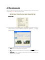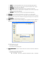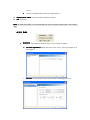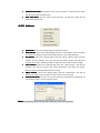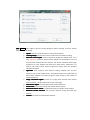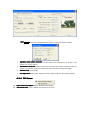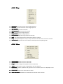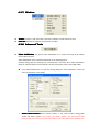
1
ACTS:
Automatic Camera Tracking
System
USER MANUAL 2.0
STATE KEY LAB OF CAD&CG,
ZHEJIANG UNIVERSITY
TABLE OF CONTENTS
1 Introduction....................................................................... 4
1.1
1.2
1.3
Product Specification............................................................................................ 4
Featured Functionalities.......................................................................................4
Technical Specifications....................................................................................... 4
1.3.1
Automatic Tracking............................................................................................ 4
1.3.2
Support for Camera Tracking Under Varying Focal Length................................5
1.3.3
User-friendly User Interface.............................................................................. 5
1.3.4
About Help.........................................................................................................5
1.3.5
Minimum System Requirements....................................................................... 5
2 Overview..............................................................................6
2.1
2.2
Image Sequence..................................................................................................... 6
Feature tracks.......................................................................................................... 6
2.2.1
Feature points................................................................................................... 6
2.2.2
Track lifetime..................................................................................................... 6
2.3 Camera tracking..................................................................................................... 6
2.3.1
The camera........................................................................................................ 6
2.3.2
Camera constraints............................................................................................7
2.3.3
Camera tracking.................................................................................................7
2.3.4
The 3D environment..........................................................................................7
3 A simple example............................................................ 8
3.1
3.2
3.3
3.4
3.5
Run ACTS.................................................................................................................. 8
Import image sequence....................................................................................... 8
Track camera......................................................................................................... 11
Save project...........................................................................................................14
Export result.......................................................................................................... 14
4 The User Interface........................................................ 16
4.1
4.2
Overview of the GUI........................................................................................... 16
The main menu bar............................................................................................ 17
4.2.1
File................................................................................................................... 17
4.2.2
Edit...................................................................................................................19
4.2.3
Actions.............................................................................................................20
4.2.4
3D Scene..........................................................................................................22
4.2.5
Play.................................................................................................................. 23
4.2.6
View.................................................................................................................23
4.2.7
Window........................................................................................................... 24
4.2.8
Advanced Tools................................................................................................24
4.2.9
Help................................................................................................................. 28
4.3
Toolbars................................................................................................................... 28
4.3.1
The main toolbar............................................................................................. 28
4.3.2
The 3D view toolbar........................................................................................ 29
4.3.3
The playback toolbar....................................................................................... 29
4.4 The project window.............................................................................................30
4.5 The main window................................................................................................. 31
4.6 The property window......................................................................................... 32
4.6.1
The project property page...............................................................................32
4.6.2
The sequence property page...........................................................................33
4.6.3
The track property page.................................................................................. 33
4.6.4
The camera property page.............................................................................. 34
4.6.5
The 3D object property page...........................................................................36
4.7 The timeline........................................................................................................... 36
4.8 The parameters graph....................................................................................... 37
4.9 List of hotkeys.......................................................................................................38
1 Introduction
1.1 Product Specification
ACTS: Automatic Camera Tracking system is an automatic camera tracking with dense depth
recovery software, which is able to effectively recover the camera parameters, and dense depth
maps from an input 2D image/video sequence. The recovered 3D data are useful for many
applications, such as video composition, 3D modeling and animation.
For examining the reconstruction quality, the user can insert a virtual 3D object into the scene,
and playback the compositing sequence to inspect whether there is a drift. 3D interactive tools
are also provided for conveniently manipulating the inserted 3D objects. Once tracking is
complete, the results can be exported for use.
1.2 Featured Functionalities
There are three main modules contained in the system, listed as follows:
� The feature tracking module
module: automatically extracts the feature points and track them.
� The camera estimation module
module: solves for the external and intrinsic camera parameters
based on the tracked feature tracks.
� The 3D object testing module
module: inserts 3D virtual objects and composite them with the video.
The compositing video can be used to examine the tracking quality.
1.3 Technical Specifications
�
�
�
Input
Input: a video sequence
Output
Output: the camera parameters, sparse 3D feature points and dense depth maps
Supported export formats
formats:
� Simple tracking format (.txt)
� 3D Studio Max (.ms)
� Maya (.ma)
1.3.1 Automatic Tracking
Our system supports to track two camera motion types, i.e. pure rotation and free-moving. The
whole process is very simple, only requiring several clicks on the buttons. Some interactive and
visualization tools are also provided, allowing the user to conveniently examine the tracking
quality.
1.3.2 Support for Camera Tracking Under Varying Focal
Length
ACTS can efficiently and robustly handle the long sequences with varying focal length, without
requiring any prior knowledge.
1.3.3 User-friendly User Interface
The graphical user interface is provided for easy use. The tracking results can be visualized in both
2D and 3D ways. In addition, 3D objects can be imported and manipulated to examine the
tracking quality.
1.3.4 About Help
To make this users’ guide more readable, the table below lists several notations that will occur in
later parts of this document.
button
menu�submenu
Keyboard
keyword Actio
n
1.3.5 Minimum System Requirements
�
�
�
�
�
�
Microsoft Windows 2000, XP or Server 2003
Intel Pentium III 600 MHz
Display resolution of 1024*768 pixels, 24-bit color
OpenGL compatibility
128Mb of memory. 512Mb or higher recommended.
100Mb of free disk space.
2 Overview
2.1 Image Sequence
The input should be an image or video sequence. The system does not directly support a video
format file. The user should decompress the video clips into image sequences beforehand. Most
image formats are supported, such as BMP, JPEG, PNG etc.
Notice
Notice: For not missing your results, please save the project whenever necessary.
2.2 Feature tracks
2.2.1 Feature points
Feature points refer to the interesting points in the image. The system can automatically detect
the feature points and match them among consecutive frames.
2.2.2 Track lifetime
The matched feature points constitute the feature tracks. It corresponds to a 3D point in the
scene. A key characteristic of feature tracks is the track lifetime—the number of frames over
which a point is visible. Long tracks are more useful than short tracks. ACTS allows the user to
specify the minimum track length, so that the feature tracks short than the specified threshold
will not be used for camera estimation.
2.3 Camera tracking
2.3.1 The camera
Each image frame has intrinsic and external camera parameters. The external camera parameters
contain camera rotation and translation. The intrinsic parameters include:
� Principal point
point: the center of the lens. Its default value is the center of the image.
Focal
length
�
length: the distance between the optical center and the focus plane.
� Pixel aspect
aspect: the ratio of (pixel height)/(pixel width). The formula can be further expanded
into (width of image resolution/width of film)/(height of image resolution/height of film).
For example, if the film is 32mm*24mm and the image taken has resolution 640*480, then
the ration is (640/32)/(480/24) = 1.0. For most cameras, the ratio is close to 1.0.
� Radial distortion
distortion: current version assumes there is no radial distortion.
It should be noted that the current version of ACTS assumes the principal point is at the image
center, the pixel aspect is 1.0 and there is no radial distortion. The focal length can be unknown
and varied.
2.3.2 Camera constraints
Besides internal parameters, users are allowed to select some prior constraints on camera
motion type, i.e. pure rotation, or free-moving. See 4.6.2.
2.3.3 Camera tracking
The camera tracking step solves for the camera motion as well as the 3D positions of the sparse
feature tracks.
2.3.4 The 3D environment
After camera estimation, the user can immediately review the tracking results. The provided 3D
view mode allows the user to inspect the recovered 3D trajectory and 3D positions of the tracked
feature points. The user can insert a 3D object into the 3D scene. The interactive 3D tool allows
the user to freely change the position, orientation and scale of the inserted object.
3 A simple example
3.1 Run ACTS
3.2 Import image sequence
�
click
,or press Ctrl+I to open the dialog to import image sequence, as in Figure 3-1.
Figure 3- 1 dialog for importing image sequence
�
click browse, and select the first image of the image sequence, as in Figure 3- 2.
Figure 3- 2 choose the first image of the sequence
�
click OK, import 140 frames of image sequence, as in Figure 3- 3.
Figure 3- 3 import image sequence
�
Figure 3- 4 shows the imported sequence.
Figure 3- 4 image sequence
�
Configure the camera (type: known/constant/variable focal length), as shown in Figure
3-5.
Figure 3- 5 camera configuration
3.3 Track camera
1)
Click actions�quick track,or press Ctrl+Q to open the tracking dialog, Figure 3-6.
2)
Click feature to open the feature tracking dialog, Figure 3-6.
Figure 3- 6 tracking dialog
3)
Set the minimum track length. In this example, set it to 15. Click OK, as shown in Figure 3- 7.
Figure 3- 7 feature tracking options
4)
Click process and wait, Figure 3-8. If you wanna stop the solving, Click stop.
Figure 3-8 start tracking
5)
After process completes, click exit, Figure 3-9.
Figure 3- 9 tracking completes
6)
Figure 3-10 shows the camera tracking result.
Figure 3- 10 tracking result
7)
Figure 3-11 shows the recovered 3D structure of the scene.
Figure 3- 11 3D structure of the scene
3.4 Save project
Click File� save project, or press Ctrl+S, choose file path, input file name, and click save, Figure
3-12.
Figure 3- 12 save project
3.5 Export result
Click File � Export, or press key Ctrl+E, choose the exporting path, file name and click save,
Figure 3-13.
Figure 3- 13: export 3D points and camera parameters
The format of Simple Camera Track File is defined as follows:
The number of frames
Intrinsic Matrix (3*3)
Rotational Matrix (3*3)
Translational Vector
…
The number of 3D Points
XYZ
….
4 The User Interface
4.1 Overview of the GUI
This is the overall GUI of ACTS.
Main menu bar
Project window
Main toolbar
3D view toolbar
Main window
Property window
Playback bar
Timeline
�
�
�
�
�
�
�
Status bar
Main menu bar
bar: the main menu includes all commands.
Project window
window: users can select project file, image sequence, feature points, camera, and
3D objects here. The related information is displayed in the property window.
Main window
window: allows users to view the scene in either 2D or 3D mode. It shows the image
frames, feature points, and 3D objects. Detailed description can be found in section 4.5.
Property window
window: specific information relating to the currently selected object would be
displayed here. For detailed description, please refer to section 4.6.
Timeline
Timeline: allows users to browse the image sequence.
Parameters graph
graph: visualizes how the camera’s parameters change over time.
Status bar
bar: status information of the application.
4.2 The main menu bar
Here is a quick look at the main menu bar. In the following sections, each menu and the
corresponding sub-menu will be introduced in details.
4.2.1 File
�
Import Sequence: imports an image sequence. The filenames of the images should be in a
numbered format, for example: img000.bmp, img001.bmp, img002.bmp, …, or img0.jpg,
img1.jpg, img2.jpg, ….
In the “Import Sequence” dialog, the user can set several parameters:
� Label: default name of the imported image sequence.
� File: the filename of the first image frame in the sequence. Click browse to select the
image.
� Motion type: the user can decide the motion type of the camera. It could be either
“Rotation Only” or “Free Move”.
�
�
�
�
�
�
�
�
�
�
Camera: the corresponding default camera name of the imported image sequence.
Interlace: specifies whether the image frames are interlaced. Default value is “None”.
Frame rate: the frame rate of the sequence.
Start Frame: the offset of the start frame, from the specified first image frame.
Step: specifies the step in which frames are imported. If this is set to N, then ACTS
imports 1 frame from every N frames.
End Frame: the offset of the last frame, from the specified first image frame.
Load Project
Project: loads a previously saved project, in the format of “.act” (ACTS Project).
Save Project
Project: saves the current project. If it is a new project, ACTS would let the user select a
location and input a project name; otherwise, the program will simply save to the previously
loaded project.
…: saves the project as another file.
Save Project As
As…
Export
Export: exports the results of camera tracking to files compatible with txt file, 3DSMax or
Maya format. User can also scale the 3D coordinates of all feature points while exporting.
The exported data may include:
� The camera’s parameters;
� 3D coordinates of all feature points.
�
Import Feature Tracks
Tracks: import the feature tracks from a text file. The format is defined as
follows:
� The first line is the number of track count;
� Then list the property for each track:
� Track length, 3D valid (“1” indicates the 3D position is valid), 3D position
�
�
�
(X, Y, Z),
Frame no, image position; frame no, image position; ….
Export Feature Tracks
Tracks: export the feature tracks to a text file.
Exit
Exit: exits ACTS.
Note
Note: To avoid losing data, it is recommended that users save their projects after each tracking
step.
4.2.2 Edit
�
Preference
Preference: the preference of ACTS. There are two options as follows:
�
3D Scale Adjustment: adjust the scale of the scene. Type the number, and
click “Adjust”.
�
3D View: set view frustum, point size, line with, and background color.
�
�
Estimate Track Color
Color: estimate the color of each 3D point. The 3D view will render
the 3D points with estimated color.
Clear Track Color
Color: clear the color of each 3D point. The 3D view render the 3D
points with default color.
4.2.3 Actions
�
�
�
�
�
�
Quick Track
Track: opens the tracking dialog and checks all steps.
Track Feature
Feature: opens the tracking dialog. Only the “Track Feature” will be checked.
This action will detect and link all the feature points in the image sequence.
Key Frames
Frames: opens the tracking dialog. Only the “Select Superior Tracks and Key
Frames” will be checked. This step will link the feature points and select the
superior tacks whose trajectory length is larger than the preset minimum length.
Solve Camera
Camera: opens the tracking dialog. Only the “Solve Camera” step will be
checked. This step can recover the camera parameters and sparse 3D points,
which must be performed after feature tracking.
Adjust Camera
Camera: opens the tracking dialog. Only the “Adjustment” step will be
checked. This step can be used if the solve camera is not very good.
Estimate 3D Points
Points: The user can use this function to estimate the 3D positions of
more feature tracks, not only superior tracks.
Notice
Notice: the operations above actually don’t differ very much from each other.
Click feature on the right to open the setting dialog for feature tracking. There are various
parameters in the dialog:
� Option: choose to track all frames or only selected frames.
� Tracking Range: specifies the start and end frames for feature tracking.
� Minimum Track Length: minimum trajectory length of a feature track. It is a
very important parameter which directly affects the computation time and
reconstruction quality! Because structure and motion estimation with longer
trajectories is more reliable and robust than with shorter trajectories, our
system only selects those feature trajectories longer than the specified
minimum threshold.
� Algorithm: ACTS supports three feature tracking methods. SIFT and KLT
method is just as the standard ones. The Hybrid method is a combination of
SIFT and KLT methods. The slider bar gives a quick tuning on the number of
extracted features.
� Image Presmooth Sigma: smooth the image with Gaussian filter before
feature tracking. This will reduce the noise in the image.
� Start Octave Sigma: the start sigma of SIFT feature detection.
� Enable Filter: control the density and number of SIFT feature.
� Maximum Feature Count: the extracted maximum number of SIFT feature.
� Minimum Feature Distance: the minimum distance among extracted SIFT
features.
� Preview: a preview of extracted SIFT features.
Click camera to open the setting dialog for camera tracking. Parameters include:
�
�
�
�
Optimize Initial Frames Selection: use the initial frame selected by our system or by
default (i.e. the first frame).
Smoothness Constraint: impose smoothness constraint for camera translation and focal
length. It is especially useful for tracking the sequences with varying focal length.
Manual Track: not available.
Full Adjustment: use bundle adjustment for the whole sequence. Not used by default.
4.2.4 3D Scene
�
�
Import Wavefront Object
Object: import Wavefront .obj models.
Add Virtual Cube
Cube: insert a default virtual cube to the scene.
4.2.5 Play
�
�
�
�
�
�
�
�
�
�
Goto Start
Start: go to the fist frame of the image sequence.
Goto End
End: go to the last frame of the image sequence.
Step Forward
Forward: go to the next frame.
Step Backward
Backward: go to the previous frame.
Stop
Stop: stop playing the image sequence.
Play Forward
Forward: play the image sequence.
Play Backward
Backward: play the image sequence reversely.
Once
Once: stop playing the sequence when the last frame is reached.
Loop
Loop: playing the sequence in loops. Jump to the first frame after the last frame is reached.
Auto-Reverse
Auto-Reverse: when the first or last frame is reached, reverse the playing order.
4.2.6 View
�
�
�
�
�
�
�
View 2D Mode
Mode: view the scene in 2D mode.
View 3D Mode
Mode: view the scene in 3D mode.
Image
Image: whether images are displayed in the main window.
Tracks
Tracks: whether feature tracks are displayed in the main window.
Predictions
Predictions: whether predictive 3D projections of the feature points are displayed in the
main window.
Frame Index
Index: whether the frame index is shown.
Scene Coordinate
Coordinate: whether the coordinate axis of the 3D scene is shown.
4.2.7 Window
�
�
Toolbars
Toolbars: contains a sub-menu that controls the visibility of each window in ACTS.
Status Bar
Bar: determines whether the status bar is visible.
4.2.8 Advanced Tools
�
Video Stabilization: the goal of video stabilization is to remove annoying shaky motion
from a video sequence.
Video Stabilization tool is implemented based on the following paper:
Guofeng Zhang, Wei Hua, Xueying Qin, Yuanlong Shao, and Hujun Bao. Video Stabilization
Based on a 3D Perspective Camera Model. The Visual Computer, 25(11): 997-1008, 2009.
�
Click “Video Stabilization” to open the setting dialog for video stabilization. There are
various parameters in the dialog:
�
Motion Model Selection: three motion models, i.e. 3D camera model, homography
model and affine model. If you select “3D camera model”, you should first track
features and solve camera. For other two models, you only need to track features first.
�
�
�
�
�
If you select 3D Camera model, you need to set the smoothness weight.
Motion Filtering: “Gaussian Filtering” is available for “Homography Model” and “Affine
Model”; “Linear Optimization” is available for “3D Camera Model”.
View Warping: only available for “3D Camera Model”.
Output: specify the file path of the stabilized sequence.
Steps: there are three steps. Just click “Run Steps 1-3”.
Video Depth Recovery (VDR):
The goal of VDR is to automatically recovery a set of dense depth maps from a video
sequence. This version can handle a high resolution image sequence. Given a video
sequence with very large resolution, the user can run VDR tool in a down-sampled sequence,
and then upsample the estimated depth maps for the original sequence, in addition, the
user also can equally divide the image to a set of blocks (neighboring blocks has overlapping)
and compute the depths for each block independently.
VDR is implemented based on the following two papers:
[1] Guofeng Zhang, Jiaya Jia, Tien-Tsin Wong, and Hujun Bao. Consistent Depth Maps
Recovery from a Video Sequence. IEEE Transactions on Pattern Analysis and Machine
Intelligence (TPAMI), 31(6):974-988, 2009.
[2] Guofeng Zhang, Zilong Dong, Jiaya Jia, Liang Wan, Tien-Tsin Wong, and Hujun Bao.
Refilming with Depth-Inferred Videos. IEEE Transactions on Visualization and Computer
Graphics (TVCG), 15(5):828-840, 2009.
There are three steps contained in VDR, listed as follows:
� Depth Initialization
Initialization: initialize the depth map for each frame independently.
� Bundle Optimization
Optimization: iteratively refine the depth maps associating multiple frames.
� Depth-Level Expansion
Expansion: further improve the depth precision by increasing the number
of depth levels.
� Click the above items or “Run All” to open the setting dialog for depth recovery. There
are various parameters in the following dialogs:
�
�
�
�
Start, End: specifying the range of the frames that are needed to compute the depth
maps.
Passes: the pass number of Bundle Optimization and Depth-level Expansion.
Output Tmp Data: output the intermediate data to TMP directory, for debugging or
visualization.
Estimate Dsp. Range Automatically: Automatically Estimate the disparity range
according to the recovered sparse 3D points.
Generally, most parameters can just use the default values. The parameters highlighted with red
rectangles may need to adjust for different sequences.
Resample
� Block|
Block|Resample
Resample:: This group of parameters indicates the strategy for large resolution
image. The first two parameters. “X” and “Y” represent the partition number of the
image width and height, respectively. “Overlap” means that two neighboring blocks
should have Overlap% overlapping. If the image resolution is large, you should set “X”
and “Y” larger or set “Resample” small (e.g. 0.5), especially for GPU acceleration. If
“Resample” < 1, the program will downsample the sequence for depth recovery, and
then upsample the estimated depth maps with further depth refinement.
�
Neighbor Frames Selection: For each frame, how to select its neighboring frames
for depth recovery is important, including the frame interval and the maximum number.
Generally, the default setting is ok. However, for a low-frame-rate sequence or sparse
wide-baseline images, the frame step and the maximum frame selection count should
be set smaller. The number of selected frames will directly affect the running time.
�
Meanshift Segmentation: the parameters of mean-shift. Generally, the default
parameters are ok.
� Disparity Configuration:
a) Level Num: the number of disparity levels used for first-pass Belief Propagation
optimization. It directly affects the running time and memory requirement.
b) Min. Dsp & Max. Dsp: the disparity range of the scene. If the disparity range is [0,0.01],
it means that the nearest depth is 100, and the farthest depth is infinite. VDR can
automatically estimate the disparity range with the estimated sparse 3D points. For
providing a more accurate bounding box, the user is allowed to manually specify the
disparity range.
Depth
Expansion
�
Expansion::
a) Sub-Levels
Sub-Levels:: the number of expanded disparity levels for each iteration during
hierarchical BP optimization. If the value is 10, each disparity is further quantized into
10 levels.
b)
�
�
Sub-Iter: the hierarchical iteration number of BP optimization. If the initial disparity
level number is 101, with two iterations, the disparity level number should be 10001.
Geometric Coherence Measure: measure the geometric coherence in image space or
disparity space.
System: set if use GPU and the number of working CPU threads. They could be set
simultaneously.
The estimated depth maps are stored in DATA directory. You can refer to the
following site for the introduction of depth data format:
http://www.cad.zju.edu.cn/home/gfzhang/projects/videodepth/data/
By click “Save Models”, you also can output the obj 3D models for each
estimated depth map, which are also saved in DATA directory and can be viewed
in 3D software, such as Meshlab, 3D MAX etc.
�
4.2.9 Help
�
About ACTS
ACTS: copyrights information about ACTS.
4.3 Toolbars
There are three toolbars in ACTS: the main toolbar, the 3D View toolbar, and the playback toolbar.
4.3.1 The main toolbar
The main toolbar contains buttons that correspond to the basic project management, and
playback mode. Associated commands for each button are illustrated as follows:
�
import image sequence
�
play once
�
load project
�
auto reverse
�
save project
�
loop
4.3.2 The 3D view toolbar
The 3D toolbar contains buttons that correspond to commands involving the 3D scene, such as
importing 3D models, translation, rotation, etc..
�
�
�
�
�
import .vof file
�
translate on the Z-axis
�
translate on the viewing plane
�
rotate
�
scale
save virtual objects into .vof file
import Wavefront .obj model
remove virtual object
select virtual object
�
free operations
Note
Note: after activating the free operations tool, holding specific hotkey and dragging the left
button will operate on the selected 3D object. In summary, hold Alt to scale, hold z to translate in
the Z direction, hold Ctrl to translate the object in the current viewing plane, hold Shift to rotate
the object,.
4.3.3 The playback toolbar
The playback toolbar corresponds to the “play” menu, which is described in section 4.2.5.
�
go to first frame
�
play forwards
�
step backwards (A)
�
step forward (D)
�
play backwards
�
go to last frame
�
stop
4.4 The project window
�
browse the sequence quickly
The overall information of the working project is shown in the project window in a tree structure.
The root node represents the project, with four major child nodes representing the image
sequence, all feature points, the camera, and the 3D objects, respectively. When the user
double-clicks one of the nodes, the corresponding property page in the property window will be
activated and show the related information. The nodes in the project tree are explained as
follows:
�
�
project file
file: the working project file name.
image sequence
sequence: the imported image sequence. Currently, ACTS only supports one
image sequence in one project.
�
auto tracks
tracks: sparse feature points recovered by ACTS.
�
feature point groups
groups: the feature points are grouped into groups of 10000.
�
invalid feature tracks
tracks: tracks with trajectory length less than the “minimum track
length” (see section 4.2.23). They are ignored in camera solving and don’t have valid 3D
structure.
�
valid feature tracks
tracks: tracks with trajectory length larger than the “minimum track
length”. They are included in camera solving, and their 3D structures are reconstructed after
tracking.
�
camera
camera: the camera of the image sequence. Currently, ACTS only supports one camera
in one project.
�
3D objects
objects: here shows the names of all inserted 3D objects in the scene.
Note
Note: the selected item will be displayed in bold letters; right-click on the items for menus.
4.5 The main window
In the main window, valid feature points are displayed in green, and their corresponding 3D
points’ projection in yellow. Invalid feature points are displayed in red.
Image
Valid
feature
point
(green)
Invalid
feature
point
(Red)
Current frame index
3D object
3D object
Camera of current frame
3D Feature points
Camera
Camera’’s trajectory
The main window can display the scene in both 2D mode and 3D mode. The 2D view mainly
displays the image sequence and feature points, while the 3D view presents the 3D
reconstruction result of the scene.
�
�
�
�
�
�
Image
mage: current image.
Valid feature points
points: displayed in green, with their 3D points’ projection marked in yellow.
Invalid feature points
points: displayed in red and have no 3D information.
The selected feature point
point: highlighted and labeled.
Current frame index
index: the frame number.
The 3D object
object: imported by the user, in the format of Wavefront object(.obj). The user can
access the tools in the 3D view toolbar to operate the object.
� Trajectory of the camera
camera: the trajectory of the camera in the image sequence.
� Camera of current frame
frame: illustration of the camera in current frame.
Note
Note: when no 3D tool is activated, users can scale and translate the 2D view with mouse. Hit
space to restore the position of the image in 2D view. Hit enter to restore the 3D transform in 3D
view.
4.6 The property window
4.6.1 The project property page
�
General
1) Label
Label: name of the project
File
2) File: path of the project file
�
State
1) Sequence
Sequence: indicates whether an image sequence has been imported.
2) Tracks
Tracks: indicates whether feature points tracking has been done.
3) Camera
Camera: indicates whether camera solving has been done.
Note
Note: The camera solving step can only be performed when feature tracking is completed, which
is in turn preceded by importing the image sequence.
4.6.2 The sequence property page
�
General
All the information here is actually specified when the image sequence is imported. Please
see section 4.2.1.
�
Advanced
1) Initial frame
frame: Solving the sequence from the beginning is usually not a good solution.
Our system can automatically select the optimal initial frame for structure and motion
initialization. In general, user does not need to manually set it.
2) Key frames
frames: Since solving all frames simultaneously is not efficient, our system first
estimates the structure and motion in key frames, and then solve other frames. The
“initial frame” is selected from the key frames.
3) All
All: All frames of the sequence.
4.6.3 The track property page
�
General
1) Label
Label: the name of the feature point
2) Frame
Frame: the frame index of current frame displayed in the main window.
Range
3) Range: specifies the frames on which the trajectory of the selected feature point exists.
�
Computation result
1) 2D coordinates
coordinates: 2D coordinates of the feature point in the image.
2) 3D coordinates
coordinates: 3D coordinates of the reconstructed feature point in the 3D space.
3) Error level
level: for valid feature tracks, this is set to “Bundle Adjust” or “Outlier”. Otherwise,
the error level is “uninitialized”.
4) Residual
Residual: the reprojection error of the selected feature point in current frame.
5) Average res
res: the average reprojection error of the selected feature track.
4.6.4 The camera property page
�
General
1) Label
Label: name of the camera.
2) Film width
width: width of the film
3) Film height
height: height of the film
4) Unit
Unit: the measurement unit for the film’s width and height.
5) Resolution
Resolution: resolution of the images in the sequence
6) Ratio
Ratio: ratio of width to height
7) Pixel aspect
aspect: defined in section 2.3.1
�
Advanced
1) Focal length constraint type
type: if this is set to be “user fixed”, then the next parameter,
“Initial”, would be used throughout the solving process as the camera’s focal length.
The other two options both consider “Initial” as the initial value for the camera solving
step, and “constant” means that the camera’s focal length in the whole sequence
remains constant, while “variable” allows for changing focal length.
2) Initial
Initial: initial value of the camera’s focal length.
3) Principal point
point: the camera’s optical center, described in section 2.3.1.
4) Radial distortion
distortion: also described in section 2.3.1.
�
Parameters
1) Focal length
length: focal length of the camera of current image frame.
2) Rotation
Rotation: rotation parameters of current frame’s camera.
3) Translation
Translation: translation parameters of current frame’s camera.
4) Radian
Radian: indicates whether radian or degree is used as the unit for rotation.
Note
Note: providing extra information about the camera would help the camera solving step for
better tracking results.
4.6.5 The 3D object property page
�
1)
General
Label
Label: default object name with index。
�
1)
2)
3)
4)
Transform
Radian
Radian: show the rotation parameters in degree or radian.
Rotation
Rotation: the rotation of the selected virtual objects, in degree of radian.
Translation
Translation: the translation of the selected virtual object.
Scale
Scale: the scale of the selected virtual object.
4.7 The timeline
Project window
Current frame
Timeline ticks
Range of trajectory
Selected trajectory
The timeline visualizes the temporal variation of the feature points.
� Range of trajectory of feature points
points: this is perhaps the most important property related to
feature points. From the figure, it is clear that some feature points can last across the whole
timeline, while some others may last only for several frames.
� Currently selected trajectory
trajectory: this will be highlighted.
4.8 The parameters graph
Selection window
Timeline scales
Current frame
Numerical scales
Parameter curve
The parameters graph visualizes the temporal variation of the camera’s parameters.
� To visualize parameters
parameters: use the mouse to selected parameters that you want to review.
Hold Ctrl for selecting multiple items. The curve corresponding to X axis will be drawn in red,
Y axis in green, and Z axis in yellow.
� Parameter curves
curves: Users can have an intuitive look at how the camera’s parameters change
over time.
Note
Note: by selecting multiple parameters, users can directly observe the relationships between
their variations.
4.9 List of hotkeys
Command
Hotkey
Import image sequence
Ctrl+I
Load project
Ctrl+L
Save project
Ctrl+S
Exit program
Ctrl+X
Configure preferences
Ctrl+P
Export to other formats
Ctrl+E
2D viewing mode
Ctrl+D
3D viewing mode
Ctrl+F
Hide/show main toolbar
Alt+4
Hide/show 3D view toolbar
Alt+5
Hide/show project window
Alt+6
Hide/show property window
Alt+7
Hide/show timeline
Alt+8
Hide/show parameters graph
Alt+9
Hide/show output window
Alt+0
12/12/
3
20
201
2/12/3