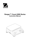
1
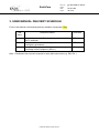
EarthCare Change Record Issue Date Sheet Description of Change 1 23.02.2009 all first issue © Astrium GmbH All rights reserved. Doc. No: Issue: Date: Page: EC.IRD.ASD.SY.00019 1 23.02.2009 2 of 30 EarthCare Doc. No: Issue: Date: Page: EC.IRD.ASD.SY.00019 1 23.02.2009 3 of 30 Table of Contents 1. INTRODUCTION ...........................................................................................................................................5 1.1 Scope of the Document ..........................................................................................................................5 1.2 References .............................................................................................................................................5 1.2.1 Applicable Documents....................................................................................................................5 1.2.2 Normative Documents....................................................................................................................5 1.2.3 Reference Documents....................................................................................................................5 1.3 Requirments Definitions .........................................................................................................................5 2. EARTHCARE USER MANUAL VOLUME CONTENT DEFINITION .............................................................7 1. INTRODUCTION ......................................................................................................................................9 1.1 SCOPE ...................................................................................................................................................9 1.2 DOCUMENTS ........................................................................................................................................9 1.3 TERMS AND DEFINITIONS ..................................................................................................................9 2. <EARTHCARE EQUIPMENT> FUNCTIONAL CHARACTERISTICS ..................................................10 2.1 FUNCTIONAL OBJECTIVES ...............................................................................................................10 2.2 PRINCIPLE OF OPERATION ..............................................................................................................10 3. <EARTHCARE EQUIPMENT> CONFIGURATION ...............................................................................10 3.1 PHYSICAL CONFIGURATION ............................................................................................................10 3.3 FUNCTIONAL CONFIGURATION .......................................................................................................12 3.4 REDUNDANCY ....................................................................................................................................12 4. <EARTHCARE EQUIPMENT> MODES ................................................................................................13 4.1 MODE DESCRIPTIONS.......................................................................................................................13 4.2 <EARTHCARE EQUIPMENT> MODE TRANSITIONS .......................................................................14 5. OPERATIONAL INTERFACES ..............................................................................................................15 5.1 CONTROL SIGNALS ...........................................................................................................................15 5.2 COMMAND MECHANISMS .................................................................................................................15 5.3 TELEMETRY MECHANISM ................................................................................................................15 6. OPERATIONS AND CONSTRAINTS ....................................................................................................16 6.1 ROUTINE OPERATIONS.....................................................................................................................16 6.2 LAUNCH, INITIAL SWITCH-ON AND IN-ORBIT CHECK OUT...........................................................16 6.3 OPERATIONS AND CONSTRAINTS FOR GROUND INITIATED RECONFIGURATIONS ...............16 6.4 GENERAL CONSTRAINTS AND LIMITATIONS .................................................................................16 7. COMMAND AND CONTROL .................................................................................................................19 8. OBSERVABILITY ...................................................................................................................................20 9. SOFTWARE ...........................................................................................................................................21 9.1 SOFTWARE FUNCTIONAL BREAKDOWN ........................................................................................21 9.2 IMPLEMENTATION OF THE PACKET UTILISATION STANDARD (EC-PUS) ..................................21 10 MICROPROCESSORS AND MEMORIES............................................................................................21 11. FAILURE DETECTION, ISOLATION AND RECOVERY (FDIR) .........................................................22 11.1. FAILURE DETECTION AND MONITORING ....................................................................................22 11.2.1 Internal Monitoring...........................................................................................................................22 11.2.2 External Monitoring..........................................................................................................................22 11.2 FAILURE ISOLATION AND RECOVERY ..........................................................................................22 12. NOMINAL PROCEDURES...................................................................................................................23 © Astrium GmbH All rights reserved. EarthCare Doc. No: Issue: Date: Page: EC.IRD.ASD.SY.00019 1 23.02.2009 4 of 30 13. CONTINGENCY RECOVERY PROCEDURES ...................................................................................25 14. <EARTHCARE EQUIPMENT> ON-GROUND OPERATION...............................................................26 15. BUDGETS ............................................................................................................................................27 16. LIST OF ABBREVIATIONS..................................................................................................................27 ANNEXES: .................................................................................................................................................28 3. USER MANUAL DELIVERY SCHEDULE ...................................................................................................30 © Astrium GmbH All rights reserved. Doc. No: Issue: Date: Page: EarthCare EC.IRD.ASD.SY.00019 1 23.02.2009 5 of 30 1. INTRODUCTION 1.1 Scope of the Document The scope of this document is to provide the requirements for the generation of the equipment user manual of the EarthCARE Space Segment. The equipment user manual will serve AIT as well as Flight Operation purposes. 1.2 References 1.2.1 Applicable Documents [AD-3] SRDB Population Requirements EC.IRD.ASD.SY.00003 [AD-5] Equipment Property Workbook Population Requirements EC.IRD.ASD.SY.00020 [AD-110] EarthCARE Packet Utilization Standard EC.STD.ASD.SY.00001 1.2.2 Normative Documents 1.2.3 Reference Documents 1.3 Requirments Definitions Requirements in this specification are identified as follows: EUM-nnn /<source>/ V : <Summary> where • "EUM" is the prefix for requirements, • "nnn" is a running number, assigned by the DOORS tool, not editable. • <source> reads either "created" when the requirement is generated by the prime, or it gives the reference requirement number from an upper level applicable document • “V” is the proposed verification method, which is either © Astrium GmbH All rights reserved. EarthCare • Doc. No: Issue: Date: Page: EC.IRD.ASD.SY.00019 1 23.02.2009 6 of 30 o "R" for Review of Design: in this document "R" means that the requirements is already covered by the proposed SIS Astrobus tool and the according documentation. In the next phase a compliance matrix will be provided which requirement is covered where in which document o "T" for Test o "I" for Inspection o "A" for Analysis <Summary> is a short heading for the requirement text The character style of the requirements text is in italic. © Astrium GmbH All rights reserved. EarthCare Doc. No: Issue: Date: Page: EC.IRD.ASD.SY.00019 1 23.02.2009 7 of 30 2. EARTHCARE USER MANUAL VOLUME CONTENT DEFINITION EUM-001 /<CREATED>/ V : <Equipment User Manual Contnt> The equipment user manual shall provide all technical information necessary to permit the customer to: Prepare and validate the EarthCARE space segment segment, including the satellite software simulator; Establish the operational databases (including TM/TC and Flight Dynamics) Operate and control the EarthCARE spacecraft in nominal and contingency cases for all phases of the mission." EUM-002 /<CREATED>/ V : <Equipment User Manual Consistency> The contents of the equipment user manual shall be internally consistent and consistent with the the equipment ICD and the related electronically readable equipment physical property work book acc. [AD-05] the equipment TM/TC ICD and the related electronically readable equipment TMTC database acc. [AD-03] EUM-003 /<CREATED>/ V : <ICD & TMTC DB version> The content of the equipment user manual shall uniquely indicate to which version of the equipment ICD and the TMTC data base it relates. EUM-004 /<CREATED>/ V : <Equipment User Manual Content > The content of the ESUM shall be consistent with the latest release of the on-board software and indicate to which versions (for equipment with software) it relates. EUM-005 /<CREATED>/ V : <Equipment Procedures> The equipment user manual shall contain all nominal and contingency operations procedures necessary for space segment operations, this also includes an initial version of any necessary Operations Timelines. The list of procedures and timelines to be generated shall be agreed between the Contractor and the customer and recorded in the User Manual. EUM-006 /<CREATED>/ V : <Procedure Validation> The procedures presented in the equipment user manual shall be validated at equipment level testing during AIV to the maximum extent. Another system, for example the SVF or EFM, can be used for specific procedures, after agreement with customer. EUM-007 /<CREATED>/ V : <Equipment User Manual Content> The equipment user manual shall be used by the contractor as a reference document during the © Astrium GmbH All rights reserved. EarthCare Doc. No: Issue: Date: Page: EC.IRD.ASD.SY.00019 1 23.02.2009 8 of 30 AIV programme. EUM-008 /<CREATED>/ V : <Operation Characteristics and Algorithms> The equipment user manual shall provide the definition of all operational characteristics associated with the control of the equipment in flight and on-ground, including any constraints or special operations. It shall also contain any algorithms or ground processing required to support operations during all phases of the mission. EUM-009 /<CREATED>/ V : <Equipment User Manual Detailed Content Definition > The equipment user manual shall be provided as defined by the content definition for the User Manuals for EarthCARE equipments. © Astrium GmbH All rights reserved. EarthCare Doc. No: Issue: Date: Page: EC.IRD.ASD.SY.00019 1 23.02.2009 9 of 30 1. INTRODUCTION 1.1 SCOPE Include the following text. “This User Manual contains all information necessary for proper operation of the integrated <EARTHCARE equipment>, to be flown on EARTHCARE. In particular, this manual describes in detail any procedure to follow and any constraint or limitation to be considered. This manual covers not only all relevant mission phases but also the on-ground operation. The current issue of this document deals with the <EARTHCARE equipment> <EM/FM>” 1.2 DOCUMENTS 1.2.1 Applicable Documents List all applicable documents for this USER MANUAL. [AD 1] [AD 2] 1.3.2 Reference Documents List all the source documents and the used issue for the information contained in this USER MANUAL. “The operational information in this document is derived form the following reference documents : [RD 1] [RD 2] “ 1.3 TERMS AND DEFINITIONS Any terms and conditions should be included here. Definition of reference frames and reference models should be included here. © Astrium GmbH All rights reserved. EarthCare Doc. No: Issue: Date: Page: EC.IRD.ASD.SY.00019 1 23.02.2009 10 of 30 2. <EARTHCARE EQUIPMENT> FUNCTIONAL CHARACTERISTICS 2.1 FUNCTIONAL OBJECTIVES Give a brief overview of the purpose of the equipment. 2.2 PRINCIPLE OF OPERATION Describe how the functionality described in the previous section is achieved and give a summary of the expected equipment performance (including relevant spec values). 3. <EARTHCARE EQUIPMENT> CONFIGURATION The objective of this chapter is to give a complete and accurate design description of the physical and functional implementation of the equipment. This should consist of 3 sections as follows • • • Physical configuration. Functional configuration Redundancy These sections are expanded below. 3.1 PHYSICAL CONFIGURATION This section should identify all physical assemblies and units in the subsystem and their physical location on the spacecraft. 3.1.1 Units and Assemblies A configuration block diagram of the equipment showing all its assemblies and units should be given in the format of . © Astrium GmbH All rights reserved. Doc. No: Issue: Date: Page: EarthCare EC.IRD.ASD.SY.00019 1 23.02.2009 11 of 30 EarthCARE Subsystem Assembly 2 Assembly 1 Unit 3 Assembly 3 Unit 11 Unit 21 Unit 31 Unit 12 Unit 22 Unit 32 Unit 13 Unit 23 Unit 33 A table listing the Configuration Item Number of each assembly / unit and whether it is the prime or redundant assembly / unit should be provided. This table should be in the following format. Name CI Description Reference R CI = Configuration Item Number R = Redundant assembly/unit <EARTHCARE Equipment> Hardware List Table 3-2-1-1: <EARTHCARE Equipment> Hardware List 3.2.2 <EARTHCARE Equipment> Assemblies & Units and their Accommodation on EARTHCARE This section should provide a physical description of the equipment assemblies and units and the accommodation of them on the EARTHCARE spacecraft. In particular the following should be covered; • description of structure and physical layout • description of thermal control hardware and its locations • description of fields of view and zones of impingement • description of mechanisms including those for deployments and releases. This description should be supported by detailed drawings contained in Annex 1 of the USER MANUAL. © Astrium GmbH All rights reserved. EarthCare Doc. No: Issue: Date: Page: EC.IRD.ASD.SY.00019 1 23.02.2009 12 of 30 3.3 FUNCTIONAL CONFIGURATION 3.3.1 Functional Block Diagram ´ Provide a functional block diagram identifying all assemblies and units, all internal interfaces and all external interfaces. Provide supporting descriptive text describing how the assemblies and units function together at equipment level and how they are interfaced to other external equipments. 3.3.2 Functional Description of <EARTHCARE Equipment> Units, Assemblies and Functions Provide a detailed functional description of each <EarthCARE Equipment> assembly, unit and functions. 3.4 REDUNDANCY Provide a detailed description of the equipment redundancy and cross-strapping. © Astrium GmbH All rights reserved. Doc. No: Issue: Date: Page: EarthCare EC.IRD.ASD.SY.00019 1 23.02.2009 13 of 30 4. <EARTHCARE EQUIPMENT> MODES 4.1 MODE DESCRIPTIONS List all the <EARTHCARE Equipment> modes. Provide a table mapping each assembly / unit status to each equipment mode using the format of Table 4.11 below. Provide a table summarising the mode characteristics using a format similar to Table 4.1-2 below. Provide a table summarising which equipment functions are active in each mode using a format similar to Table 4.1-3 below (note that HW functions description is given in section 3.3 whereas SW functions description is given in section 9.3). Modes Off XXX YYY ZZZ … Equipment Status Assembly 1 Unit 11 Unit 12 … Unit 1n Assembly 2 Unit 21 … Assembly m Unit m1 … Unit mn Table 4.1-1: < EARTHCARE Equipment> equipment status versus <EARTHCARE Equipment> modes Modes Off XXX e.g. 1553B protocol NO YES … NO … NO YYY ZZZ … Functions Table 4.1-2: Active Functions versus < EARTHCARE Equipment> Modes © Astrium GmbH All rights reserved. Doc. No: Issue: Date: Page: EarthCare EC.IRD.ASD.SY.00019 1 23.02.2009 14 of 30 4.1.x Detailed Mode Descriptions Provide a detailed description of each mode to a more detailed level of information than that contained in the tables in the previous section. If the equipment has different statuses or sub-modes within a mode then these should be described here. The circumstances that lead to these different sub-modes or statuses should also be documented here. A description of the purpose of each mode or sub-mode, why to enter and exit it and the duration spent in it should be given. 4.2 <EARTHCARE EQUIPMENT> MODE TRANSITIONS Provide a mode transition diagram showing all the equipment modes and allowed transitions between them. The trigger for each transition path should be identified (e.g. ground command, automatic nominal, internal corrective action, external corrective action, etc). Provide a table identifying the mode transition times using the format of Table 4 below. A mode transition is defined to start when the equipment leaves a defined mode and is terminated when the equipment has reached a new defined mode. In particular, for a mode transition triggered by a command, the mode transition starts when the command execution is started. 4.2.x Transition to mode x Provide a detailed description of the mode transition including the sequence of events executed (as a timeline if relevant). Where the sequence of events in the transition is dependent on the initiating trigger this should be clearly described. Likewise the effect of any other means to control the transition (such as control parameters in an initiating telecommand) should be described. Transition from Transition to Off XXX YYY ZZZ … … … Off XXX YYY ZZZ x sec y sec z sec Table 4.2-1: Mode Transition Times Transition not possible © Astrium GmbH All rights reserved. … EarthCare Doc. No: Issue: Date: Page: EC.IRD.ASD.SY.00019 1 23.02.2009 15 of 30 5. OPERATIONAL INTERFACES 5.1 CONTROL SIGNALS List all the control signal lines used by the EARTHCARE Equipment. Describe all actions and timings, both hardware and software, that take place after the activation of a control signal. Where appropriate, give references to nominal and / or contingency recovery procedures. Describe <EARTHCARE Equipment> on board time synchronisation. Describe how the <EARTHCARE Equipment>will be synchronised (e.g. describe the procedure), the resolution for maintaining the <EARTHCARE Equipment> on board time, when it shall take place (e.g. after <EARTHCARE Equipment> initialisation), the synchronisation accuracy, the recovery actions in the case of time discrepancies, setting and phase adjustments of counters / clocks, etc. State if specific synchronisation lines between the <EARTHCARE Equipment> and other EARTHCARE equipments are used. If such lines are used then describe their logical and physical characteristics. Describe how any <EARTHCARE Equipment> appendages, covers, locks, etc – if any - are commanded, i.e. the used signal lines, schedule, by which unit the process is initiated and controlled, etc. If deployment of appendages can be reversed, both processes together with their circumstances should be described. 5.2 COMMAND MECHANISMS Describe the used Command and Control interfaces logically (e.g. number of signal lines, signal characteristics (e.g. analog, digital), used protocol, interdiction times, etc) and physically (e.g. 1553B bus, discrete signal lines) in the subchapters of this chapter. Each C&C interface shall be described together with its function. 5.3 TELEMETRY MECHANISM Describe the used telemetry interfaces logically (e.g. number of signal lines, signal characteristics (e.g. analog, digital), used protocol, interdiction times, etc) and physically (e.g. 1553B bus, discrete signal lines) in the subchapters of this chapter. Note that detailed information about the down-linked packets formats should be contained in Chapter 8. © Astrium GmbH All rights reserved. EarthCare Doc. No: Issue: Date: Page: EC.IRD.ASD.SY.00019 1 23.02.2009 16 of 30 6. OPERATIONS AND CONSTRAINTS This chapter should describe the nominal <EARTHCARE Equipment> operation and list all operational constraints or limitations which apply, separated in the following sections. Any mode dependencies should be indicated unambiguously in each of the following sections. In each case the reason for the constraint or limitation and the consequence of violation should be described. Within the context of this chapter a constraint is anything which, if violated, can risk a permanent degradation of the <EARTHCARE Equipment> performance, function or reliability whereas a limitation is anything which, if violated, only risks a temporary loss or degradation of the planned operations or measurement data quality or availability. 6.1 ROUTINE OPERATIONS Describe the nominal operation of the <EARTHCARE Equipment> (routine commanding, routine maintenance, routine calibration). Give the operational timeline for the <EARTHCARE Subsystem> – if relevant. Describe the in-flight calibration process, e.g. how often, when, how and where it shall take place, the command and control procedure, the data flow, etc. If the <EARTHCARE Equipment> needs to change its modes and/or states during nominal operations then describe the foreseen activities (e.g. when and why to initiate the mode changes). If the <EARTHCARE Equipment> within one mode changes automatically between submodes then describe these processes. Provide timelines for all such automatic submode changes in the form of horizontal bar charts. 6.2 LAUNCH, INITIAL SWITCH-ON AND IN-ORBIT CHECK OUT List all operational constraints and limitations regarding the <EARTHCARE Equipment> launch, initial switchon and in-orbit check out (e.g. deployments, releases, switch-on, in-orbit calibration & verification, etc). In case deployments are foreseen, describe the deployment sequence here. 6.3 OPERATIONS AND CONSTRAINTS FOR GROUND INITIATED RECONFIGURATIONS Describe all operations and related operational constraints and limitations for ground initiated reconfigurations (i.e. main to redundant, redundant to main, use of cross strapping). 6.4 GENERAL CONSTRAINTS AND LIMITATIONS Identify and quantify all operational constraints and limitations regarding the <EARTHCARE Equipment> operation. For example, if a specific operation or mode depends on the deployment of an appendage, this should be stated here. Another aspect may be that specific operations are only allowed in specific modes. The constraints and limitations should be given for the following aspects. If no constraint or limitation exists for a particular aspect then this should be explicitly stated. Any other aspects that are not covered in section 6.3 should be included here. © Astrium GmbH All rights reserved. Doc. No: Issue: Date: Page: EarthCare EC.IRD.ASD.SY.00019 1 23.02.2009 17 of 30 6.4.1 Satellite attitude and altitude List all EARTHCARE Equipment operational constraints and limitations regarding the spacecraft attitude and altitude, e.g. equipment atomic oxygen exposure (if relevant). Additionally, if the EARTHCARE Equipment performance is a function of spacecraft attitude or altitude , the impact should be described here. 6.4.2 Shocks Using the following table list all the operational constraints and limitations regarding the <EARTHCARE Equipment> unit shock limits (g load and duration). All units, as identified in section 3.1 should be listed. If no limit applies then this should be stated. Unit Constraint Unit x x g/t ms Unit y Unit z Table 6.4.2-1: Shock limits 6.4.3 In Orbit Acceleration List all <EARTHCARE Equipment> operational constraints and limitations regarding the spacecraft accelerations and vibrations using the following table. Frequency range Nominal Operational Modes Non-Nominal Operational Modes Table 6.4.3-1: In-Orbit acceleration constraints 6.4.4 Thermal In tabular form, for each unit, provide the thermal limits which apply for an operational constraint or limitation. As a minimum this should include definition of the operational temperature range, the non-operational temperature range and the switch-on temperature range. 6.4.5 Sun Illumination List all operational constraints and limitations regarding sun illumination. For example if a unit shall not be illuminated by direct sunlight (quantify the extent and geometry) the impact should be described here. 6.4.6 Outgassing © Astrium GmbH All rights reserved. EarthCare Doc. No: Issue: Date: Page: EC.IRD.ASD.SY.00019 1 23.02.2009 18 of 30 List all operational constraints and limitations regarding the <EARTHCARE Equipment> out-gassing. For example, if a unit shall not be operated until its out-gassing is completed to a certain extent, because this could cause performance losses or is harmful in some way then this should be stated here. The out-gassing times shall be given. 6.4.7 Contamination List all operational constraints and limitations regarding the <EARTHCARE Equipment> contamination. If performance losses are expected under specific circumstances, this should be stated here. 6.4.8 Life Limited Items Using the following table list all the operational constraints and limitations regarding life limited items. All life limited items associated with their limits should be given. For each listed item a short and precise description of the limitations including the relevant unit (e.g. no. of cycles) and the mode(s), when the item will be used, shall be given. Life Limit Qual Limit TM parameter (detail) to be monitored x 36540 cycles 1000 cycles TMxx for TMyy for redundant Unit Unit Switching relays main Unit y chain selection relays … Table 6.4.8-1: Life-Limited Items of <EarthCARE Equipment> 6.4.x Other <EARTHCARE Equipment> Specific Constraints Any other constraints and limitations not already covered in section 6.3 or in this section should be detailed in additional subsections to section 6.4. © Astrium GmbH All rights reserved. EarthCare Doc. No: Issue: Date: Page: EC.IRD.ASD.SY.00019 1 23.02.2009 19 of 30 7. COMMAND AND CONTROL This chapter describes the means of controlling the EARTHCARE Equipment. Operational interfaces can be found in Chapter 5, Operations and Constraints in Chapter 6 and procedures are described in Chapters 12 and 13. A table listing all <EARTHCARE Equipment> commands available to the ground should be provided. For each command this table should include the command name, the command ID, a brief description of the command function, any mode dependency for the command, how to verify execution of the command and, if relevant, the execution time of the command. In addition to this table a description should be defined for each command giving: • • • • a pictorial representation of the command layout and structure showing each parameter as a separate field a detailed description for each parameter giving its meaning, its format and a definition of how to compute it a detailed description of the command function (including the sequence of actions performed on the subsystem) any constraints associated with the command. © Astrium GmbH All rights reserved. EarthCare Doc. No: Issue: Date: Page: EC.IRD.ASD.SY.00019 1 23.02.2009 20 of 30 8. OBSERVABILITY This chapter should give a comprehensive description of all the HK data, TM or TM packets produced by the EARTHCARE Equipment. This should include • • • the layout of each HK data, TM packet and identification of the parameters contained within each TM packet. the generation rate and trigger (cyclic or on specified event) for each packet datation information, e.g. the relative age of the data contained within the packet with respect to the time in the TM packet header. For each parameter a detailed description of its meaning and its behaviour should be given. Note : Science data produced by the equipment may be subject to the dedicated Annex 7. © Astrium GmbH All rights reserved. EarthCare Doc. No: Issue: Date: Page: EC.IRD.ASD.SY.00019 1 23.02.2009 21 of 30 9. SOFTWARE This section shall describe SW functions specific to the <EARTHCARE Equipment>. This should consist of sections as follows • • Software Functional Breakdown. Implementation of the Packet Utilisation Standard. These sections are expanded below. 9.1 SOFTWARE FUNCTIONAL BREAKDOWN This section shall give a high level overview of the <EARTHCARE Equipment> software and shall also provide a functional breakdown of the <EARTHCARE Equipment> software into its individual elements including interfaces to hardware. In particular, the following information shall be provided: • • A task description giving a mapping of SW tasks onto software modules and giving an overview of the SW implementation and scheduling, including the use of interrupts. In the case that any patches are identified to be up-linked from ground for either nominal or contingency operations, these shall be fully described including provision of the SW labels, offsets and associated word values. 9.2 IMPLEMENTATION OF THE PACKET UTILISATION STANDARD (ECPUS) This section shall describe the application and implementation of the EC-PUS into the <EARTHCARE Equipment> software including specific services, tables and other data structures as needed. Reference to SW User Maunal may be provided. 10 MICROPROCESSORS AND MEMORIES This section shall describe all microprocessors, their hardware/software interfaces and memories contained in <EARTHCARE Equipment>. The following information should be provided: • • • • • An overview of the processor memory map The method and constraints for dumping the memory to the ground (this should include allowed SW modes, limitations due to page boundaries, etc) The method and constraints for obtaining the checksum of specified areas of memory. The method and constraints for patching the memory (this should include allowed SW modes, limitations due to page boundaries, etc) Information about memory protection mechanisms (e.g. scrubbing routines, EDAC etc.) © Astrium GmbH All rights reserved. EarthCare Doc. No: Issue: Date: Page: EC.IRD.ASD.SY.00019 1 23.02.2009 22 of 30 11. FAILURE DETECTION, ISOLATION AND RECOVERY (FDIR) This chapter shall allow the ground to isolate the cause of onboard anomalies to the extent that recovery can be made using available onboard resources as e.g. redundancy. 11.1. FAILURE DETECTION AND MONITORING This section shall describe the failure detection and monitoring mechanisms applied for the <EARTHCARE Equipment> covering use of internal monitoring, external onboard monitoring and ground based monitoring. 11.2.1 Internal Monitoring List and describe the monitoring functions active within the equipment itself. Mode dependencies, monitoring frequencies, trigger thresholds and filtering values should be included. The identifier of the internal corrective action applied in the event of triggering should be identified (the detailed description of the corrective actions will be in the next section). In addition the justification for the monitoring should be given. 11.2.2 External Monitoring List and describe the monitoring functions to be performed external to the equipment (e.g. by the onboard software or Ground) . Mode dependencies, monitoring frequencies, trigger thresholds and filtering values should be included. The identifier of the external corrective action applied in the event of triggering should be identified (the detailed description of the corrective actions will be in the next section). In addition the justification for the monitoring should be given. 11.2 FAILURE ISOLATION AND RECOVERY The objective of this section is to define a logical flow of activities to allow the onboard failure to be isolated and corrected down to the level of available redundancy or equipment / unit re-boot. The activities shall be described for onboard as well for on-ground FDIR needs. The start point for this must always be the anomaly message contained in the TM (e.g. event message). The logic should be presented in the form of a flow diagram or a table with references to procedures in chapters 12 and 13 as appropriate. These failure localisations must be based on the FMECA and must either replicate information contained in the FMECA or make reference to the FMECA which must then be included as an Annex to the User Manual. © Astrium GmbH All rights reserved. EarthCare Doc. No: Issue: Date: Page: EC.IRD.ASD.SY.00019 1 23.02.2009 23 of 30 12. NOMINAL PROCEDURES All <EARTHCARE Equipment> nominal procedures shall be detailed in this chapter. Each procedure shall include a text header and a tabular body. The text header shall consist of the following: • Procedure Name consisting of a short meaningful description of the procedure and a unique identifier. The unique identifier shall be of the form FCP-xx-nnn, where - FCP denotes that the name is a nominal flight control procedure - xx is the equipment code - nnn is a counter to distinguish between different nominal flight control procedures in the equipment. • Procedure Objective consisting of a description of the principal aims of the procedure; • User Manual Reference referring to the relevant part of Chapter 6; • Initial Conditions specifying the context in which the procedure can be used, in particular the initial configuration of the equipment; • Final Configuration specifying the configuration of the equipment after the procedure has been run; • Constraints referring to any relevant constraints in chapter 6 and any constraints concerning the need for other procedures to be run either before or after this procedure. Example: Procedure Name FCP-xx-nnn: Switch GPS to Operational Mode Procedure Objective User Manual Reference Other Reference Initial Configuration This procedure switches the GPS into Operational Mode User Manual Volume 9, section x.x Final Configuration Constraints GOS in Operational Mode This procedure requires nominal platform operation GPS in Standby © Astrium GmbH All rights reserved. Doc. No: Issue: Date: Page: EarthCare EC.IRD.ASD.SY.00019 1 23.02.2009 24 of 30 The tabular body shall include • An incrementing step number • A description of the action to be performed • Identification of the TC to be sent and definition of the parameter values to be sent • Identification of the TM verification to be performed START OF PROCEDURE Step Activities TC 1 2 END OF PROCEDURE © Astrium GmbH All rights reserved. TM EarthCare Doc. No: Issue: Date: Page: EC.IRD.ASD.SY.00019 1 23.02.2009 25 of 30 13. CONTINGENCY RECOVERY PROCEDURES All <EARTHCARE Equipment> contingency recovery procedures (CRPs) shall be detailed in this chapter. Each procedure should use the same layout as used in Chapter 12. The contingency recovery procedure unique identifier shall be of the form CRP-xx-nnn where - CRP denotes that the name is a contingency recovery procedure; - xx is the equipment code; - nnn is a counter to distinguish between different contingency recovery procedures in the equipment. The structure of the procedures shall be identical to those in section 12. © Astrium GmbH All rights reserved. EarthCare Doc. No: Issue: Date: Page: EC.IRD.ASD.SY.00019 1 23.02.2009 26 of 30 14. <EARTHCARE EQUIPMENT> ON-GROUND OPERATION This chapter should describe all aspects of the subsystem operation specific to on ground operations. The following items shall be included at minimum: - Reference to Installation procedures Specific preparations for any operation of the equipment in specific test environment GSE to be used to operate the equipment Operations of the GSE On ground operations constraints (thermal …) On-ground handling constraints Special protections/provisions required for on-ground operation including safety/hazardous aspects Life limitation for on-ground operations all Specifics for individual models shall be considered, i.e. if an EM provides other characteristics or specific constraints as an FM. © Astrium GmbH All rights reserved. EarthCare Doc. No: Issue: Date: Page: EC.IRD.ASD.SY.00019 1 23.02.2009 27 of 30 15. BUDGETS This chapter should contain all operationally meaningful budgets that are relevant at equipment level. Budgets to be considered are • • • • • • • • • • • Mass Moment of inertia Mechanical Disturbance Telecommand Telemetry Measurement data rate Power Thermal dissipation Microprocessor Loads Microprocessor Memory Data Bus load. 16. LIST OF ABBREVIATIONS This chapter should contain all abbreviations as used in the main body of the User Manual. © Astrium GmbH All rights reserved. EarthCare Doc. No: Issue: Date: Page: EC.IRD.ASD.SY.00019 1 23.02.2009 28 of 30 ANNEXES: ANNEX 1 Detailed Configuration Drawings. All drawings as required by section 3.2.2. ANNEX 2 Internal Event Tables. This Annex should contain the internal command event tables, if relevant. These should detail all actions as a result of commands or autonomous actions on an event by event basis, even if they are not directly visible in the telemetry data. Relevant timing information should be included. ANNEX 3 Command and Control Diagrams. Command and control diagrams provide a diagrammatic representation of the relationship between bus level commands, acquisitions, control signals and controllable entities such as relays. They should contain representation of all controllable and observable switchable elements and give visibility of command and acquisition data interfaces. The diagrams shall include telemetry points (e.g. relay statuses) and SRDB/IRDB TM and TC names. ANNEX 4 Logic Diagrams and Truth Tables. All logic blocks involved in the command and control of equipments, if any, shall be represented in this annex as functional logic diagrams and supporting truth tables. This should include functions implemented in ASICs/FPGA’s. ANNEX 5 Source Code. This annex should include the source code for equipment processors that is delivered with Software. ANNEX 6 TM/TC ICD. This annex shall include the complete TM/TC ICD for the equipment. This shall include − A list of all unit HK telemetry parameters. For each parameter it shall include a function description with validity conditions, telecommand relationship and all technical information necessary for using it − A list of all unit commands. For each command it shall include a functional description with utilization conditions and execution verification in telemetry. For each command the execution runtime shall be outlined − This data may be included in the electronic TM/TC delivery towards the satellite reference data base ANNEX 7 Equipment Science Data Format and Processing Description This annex shall include the complete description of the science data stream of the equipment if provided. This shall include − Definition of the unit science output data, circumstance of generation, format, content and data rate, for each operational mode of the unit − Definition of the processing performed on the sensor data, the algorithms used, selection or rejection criteria (if under the responsibility of the contractor) − Definition of the required ground/SW processing of the science data ANNEX x Other Information Additional annexes should be provided for any other information that needs to be in the User Manual but whose bulk is such that it is not appropriate to include it within the main body of the User Manual. © Astrium GmbH All rights reserved. EarthCare Doc. No: Issue: Date: Page: EC.IRD.ASD.SY.00019 1 23.02.2009 29 of 30 In some cases it may also be appropriate to include a complete document within the User Manual. In this case the whole document can be attached as an annex to the User Manual.. © Astrium GmbH All rights reserved. EarthCare Doc. No: Issue: Date: Page: EC.IRD.ASD.SY.00019 1 23.02.2009 30 of 30 3. USER MANUAL DELIVERY SCHEDULE For the User Manual, the following delivery schedule is proposed (TBC). UM Issue Required Content 1 Initial Information / Functional description including TM/TC definition Complete document including all nominal and contingency procedures. Complete document, reflecting the latest state of knowledge of the Equipment. (Note 1) 2 3 Due Date PDR CDR DRB 1) Note 1: Dedicated User manuals required for each delivered model (e.g. EM, FM ..) . © Astrium GmbH All rights reserved. (Note