1
Q Corresponding MELSECNET/H
Remote I/O Module
Reference Manual
(MELSECNET/10 Mode)
-QJ72LP25-25
-QJ72LP25G
-QJ72LP25GE
-QJ72BR15
SAFETY PRECAUTIONS
(Read these precautions before using this product.)
Before using this product, please read this manual and the relevant manuals carefully and pay full attention
to safety to handle the product correctly.
The precautions given in this manual are concerned with this product only. For the safety precautions of the
programmable controller system, refer to the user's manual for the CPU module used.
In this manual, the safety precautions are classified into two levels: "
WARNING" and "
CAUTION".
WARNING
Indicates that incorrect handling may cause hazardous conditions,
resulting in death or severe injury.
CAUTION
Indicates that incorrect handling may cause hazardous conditions,
resulting in minor or moderate injury or property damage.
Under some circumstances, failure to observe the precautions given under "
CAUTION" may lead to
serious consequences. Observe the precautions of both levels because they are important for personal and
system safety.
Make sure that the end users read this manual and then keep the manual in a safe place for future
reference.
1
[Design Precautions]
WARNING
● In the case of a communication failure in the network, the status of the error station will be as follows:
Check the communication status information and configure an interlock circuit in the sequence
program to ensure that the entire system will operate safely. Failure to do so may result in an accident
due to an incorrect output or malfunction.
(1) The remote master station will hold the data before the communication error.
(2) The remote I/O station turns off all outputs. The output module of the remote I/O station can
clear/hold the output status at an error by using the remote I/O module parameters. As the
parameters are set to "clear" by default, the output module turns off the outputs at an error. If it is
required to hold the output to operate the system safely, set the parameters to "hold".
(3) When the output is set to "hold" with the Q4ARCPU (stand-alone system) and the A6RAF
(redundant system), the remote I/O station turns off all outputs. If it is required to hold the output to
operate the system safely, set the parameters of the remote I/O station to "hold".
● When connecting a peripheral with the CPU module or connecting an external device, such as a
personal computer, with an intelligent function module to modify data of a running programmable
controller, configure an interlock circuit in the sequence program to ensure that the entire system will
always operate safely. For other forms of control (such as program modification or operating status
change) of a running programmable controller, read the relevant manuals carefully and ensure that
the operation is safe before proceeding. Especially, when a remote programmable controller is
controlled by an external device, immediate action cannot be taken if a problem occurs in the
programmable controller due to a communication failure. To prevent this, configure an interlock circuit
in the sequence program, and determine corrective actions to be taken between the external device
and CPU module in case of a communication failure.
● If a communication cable is disconnected, the network may be unstable, resulting in a communication
failure of multiple stations. Configure an interlock circuit in the sequence program to ensure that the
entire system will always operate safely even if communications fail. Failure to do so may result in an
accident due to an incorrect output or malfunction.
[Design Precautions]
CAUTION
● Always reset the CPU module after changing the parameters for the CPU module or the remote I/O
module. Failure to do so, data before the change may cause malfunction.
● Do not install the control lines or communication cables together with the main circuit lines or power
cables. Keep a distance of 100mm or more between them. Failure to do so may result in malfunction
due to noise.
2
[Installation Precautions]
CAUTION
● Use the programmable controller in an environment that meets the general specifications in the user's
manual for the CPU module used. Failure to do so may result in electric shock, fire, malfunction, or
damage to or deterioration of the product.
● To mount the module, while pressing the module mounting lever located in the lower part of the
module, fully insert the module fixing projection(s) into the hole(s) in the base unit and press the
module until it snaps into place. Incorrect mounting may cause malfunction, failure or drop of the
module.
When using the programmable controller in an environment of frequent vibrations, fix the module with
a screw.
● Tighten the screws within the specified torque range. Undertightening can cause drop of the screw,
short circuit, or malfunction. Overtightening can damage the screw and/or module, resulting in drop,
short circuit, or malfunction.
● Shut off the external power supply (all phases) used in the system before mounting/removing a
module or connecting/disconnecting a connector. Failure to do so may result in damage to the
product.
For the remote I/O stations of function version D or later, online module change can be performed.
Note that there are restrictions on the modules that can be replaced online, and each module has its
predetermined replacement procedure.
For details, refer to the online module change in the Q Corresponding MELSECNET/H Network
System Reference Manual (Remote I/O network).
● Do not directly touch any conductive parts and electronic components of the module.
Doing so can cause malfunction or failure of the module.
3
[Wiring Precautions]
WARNING
● Shut off the external power supply (all phases) used in the system before installation and wiring.
Failure to do so may result in electric shock or damage to the product.
[Wiring Precautions]
CAUTION
● Individually ground the FG terminal of the programmable controller with a ground resistance of 100
or less. Failure to do so may result in electric shock or malfunction.
● Check the rated voltage and terminal layout before wiring to the module, and connect the cables
correctly.
Connecting a power supply with a different voltage rating or incorrect wiring may cause a fire or
failure.
● Connectors for external devices and coaxial cables must be crimped or pressed with the tool specified
by the manufacturer, or must be correctly soldered. Incomplete connections may cause short circuit,
fire, or malfunction.
● Place the cables in a duct or clamp them.
If not, dangling cable may swing or inadvertently be pulled, resulting in damage to the module or
cables or malfunction due to poor contact.
● Tighten the terminal screws within the specified torque range.
Undertightening can cause short circuit, fire, or malfunction.
Overtightening can damage the screw and/or module, resulting in drop, short circuit, or malfunction.
● When disconnecting the cable from the module, do not pull the cable by the cable part. For the cable
with connector, hold the connector part of the cable. For the cable connected to the terminal block,
loosen the terminal screw. Pulling the cable connected to the module may result in malfunction or
damage to the module or cable.
● Prevent foreign matter such as dust or wire chips from entering the module.
Such foreign matter can cause a fire, failure, or malfunction.
● A protective film is attached to the top of the module to prevent foreign matter, such as wire chips,
from entering the module during wiring.
Do not remove the film during wiring.
Remove it for heat dissipation before system operation.
● Mitsubishi programmable controllers must be installed in control panels.
Connect the main power supply to the power supply module in the control panel through a relay
terminal block.
Wiring and replacement of a power supply module must be performed by qualified maintenance
personnel with knowledge of protection against electric shock.
For wiring methods, refer to the QCPU User's Manual (Hardware Design, Maintenance and
Inspection).
4
[Startup and Maintenance Precautions]
WARNING
● Do not touch any terminal while power is on. Doing so will cause electric shock or malfunction.
● Shut off the external power supply (all phases) used in the system before cleaning the module or
retightening the terminal screws or module mounting screws. Failure to do so may result in electric
shock or cause the module to fail or malfunction.
[Startup and Maintenance Precautions]
CAUTION
● Before performing online operations (especially, program modification, forced output, and operating
status change) for the running CPU module on another station from GX Developer over the
MELSECNET/10 network, read relevant manuals carefully and ensure the safety.
Improper operation may damage machines or cause accidents.
● Do not disassemble or modify the modules.
Doing so may cause failure, malfunction, injury, or a fire.
● Use any radio communication device such as a cellular phone or PHS (Personal Handy-phone
System) more than 25cm (9.85 inches) away in all directions from the programmable controller.
Failure to do so may cause malfunction.
● Shut off the external power supply (all phases) used in the system before mounting/removing a
module or connecting/disconnecting a connector. Failure to do so may cause the module to fail or
malfunction.
For the remote I/O network systems of function version D or later, online module change can be
performed. Note that there are restrictions on the modules that can be replaced online, and each
module has its predetermined replacement procedure.
For details, refer to the online module change in the Q Corresponding MELSECNET/H Network
System Reference Manual (Remote I/O network).
● After the first use of the product, do not mount/remove the module to/from the base unit more than 50
times (IEC 61131-2 compliant).
Exceeding the limit of 50 times may cause malfunction.
● Before handling the module, touch a conducting object such as a grounded metal to discharge the
static electricity from the human body.
Failure to do so may cause the module to fail or malfunction.
[Disposal Precautions]
WARNING
● When disposing of this product, treat it as industrial waste.
5
CONDITIONS OF USE FOR THE PRODUCT
(1) Mitsubishi programmable controller ("the PRODUCT") shall be used in conditions;
i) where any problem, fault or failure occurring in the PRODUCT, if any, shall not lead to any major
or serious accident; and
ii) where the backup and fail-safe function are systematically or automatically provided outside of
the PRODUCT for the case of any problem, fault or failure occurring in the PRODUCT.
(2) The PRODUCT has been designed and manufactured for the purpose of being used in general
industries.
MITSUBISHI SHALL HAVE NO RESPONSIBILITY OR LIABILITY (INCLUDING, BUT NOT
LIMITED TO ANY AND ALL RESPONSIBILITY OR LIABILITY BASED ON CONTRACT,
WARRANTY, TORT, PRODUCT LIABILITY) FOR ANY INJURY OR DEATH TO PERSONS OR
LOSS OR DAMAGE TO PROPERTY CAUSED BY the PRODUCT THAT ARE OPERATED OR
USED IN APPLICATION NOT INTENDED OR EXCLUDED BY INSTRUCTIONS, PRECAUTIONS,
OR WARNING CONTAINED IN MITSUBISHI'S USER, INSTRUCTION AND/OR SAFETY
MANUALS, TECHNICAL BULLETINS AND GUIDELINES FOR the PRODUCT.
("Prohibited Application")
Prohibited Applications include, but not limited to, the use of the PRODUCT in;
• Nuclear Power Plants and any other power plants operated by Power companies, and/or any
other cases in which the public could be affected if any problem or fault occurs in the PRODUCT.
• Railway companies or Public service purposes, and/or any other cases in which establishment of
a special quality assurance system is required by the Purchaser or End User.
• Aircraft or Aerospace, Medical applications, Train equipment, transport equipment such as
Elevator and Escalator, Incineration and Fuel devices, Vehicles, Manned transportation,
Equipment for Recreation and Amusement, and Safety devices, handling of Nuclear or
Hazardous Materials or Chemicals, Mining and Drilling, and/or other applications where there is a
significant risk of injury to the public or property.
Notwithstanding the above, restrictions Mitsubishi may in its sole discretion, authorize use of the
PRODUCT in one or more of the Prohibited Applications, provided that the usage of the PRODUCT
is limited only for the specific applications agreed to by Mitsubishi and provided further that no
special quality assurance or fail-safe, redundant or other safety features which exceed the general
specifications of the PRODUCTs are required. For details, please contact the Mitsubishi
representative in your region.
6
INTRODUCTION
Thank you for purchasing the Mitsubishi MELSEC-Q series programmable controllers.
This manual describes the procedures, system configuration, parameter settings, functions, programming, troubleshooting of
the MELSECNET/10 mode for the MELSECNET/H remote I/O module.
Before using this product, please read this manual and the relevant manuals carefully and develop familiarity with the
functions and performance of the MELSEC-Q series programmable controller to handle the product correctly.
When applying the program examples introduced in this manual to an actual system, ensure the applicability and confirm that
it will not cause system control problems.
Please make sure that the end users read this manual.
COMPLIANCE WITH EMC AND LOW VOLTAGE
DIRECTIVES
(1) Method of ensuring compliance
To ensure that Mitsubishi programmable controllers maintain EMC and Low Voltage Directives when incorporated
into other machinery or equipment, certain measures may be necessary. Please refer to one of the following
manuals.
• QCPU User's Manual (Hardware Design, Maintenance and Inspection)
• Safety Guidelines
(This manual is included with the CPU module or base unit.)
The CE mark on the side of the programmable controller indicates compliance with EMC and Low Voltage
Directives.
(2) Additional measures
To ensure that this product maintains EMC and Low Voltage Directives, please refer to one of the manuals listed
under (1).
7
RELEVANT MANUALS
(1) CPU module user's manual
Manual name
Description
<Manual number (model code)>
QCPU User's Manual (Hardware Design, Maintenance
Specifications of the hardware (CPU modules, power supply modules, base
and Inspection)
units, extension cables, memory cards, SD memory cards, extended SRAM
cassettes, and batteries), system maintenance and inspection, troubleshooting,
<SH-080483ENG, 13JR73>
and error codes
(2) Reference manual
Manual name
Description
<Manual number (model code)>
Q Corresponding MELSECNET/H Network System
System configuration, performance specifications, procedures before operation,
Reference Manual (Remote I/O network)
parameter settings, functions, programming, and troubleshooting of the
MELSECNET/H network system (remote I/O network) with the MELSEC-Q series
<SH-080124, 13JF96>
MELSECNET/H remote I/O module
Type MELSECNET/10 Network System (Remote I/O
System configuration, performance specifications, procedures before operation,
network) Reference Manual
parameter settings, functions, programming, and troubleshooting of the
MELSECNET/10 network system (remote I/O network) with the MELSEC-A
<SH-3509, 13JE72>
series MELSECNET/10 remote I/O module
For QnA/Q4AR MELSECNET/10 Network System
System configuration, performance specifications, procedures before operation,
Reference Manual
parameter settings, functions, programming, and troubleshooting of the
MELSECNET/10 network system with the MELSEC-QnA series MELSECNET/10
<IB-66690, 13JF78>
remote I/O module
(3) Transition handbook
Handbook name
Description
<Number>
Transition from MELSEC-A/QnA (Large Type) Series to
Q Series Handbook (Fundamentals)
<L08043ENG>
Transition from MELSEC-A/QnA (Large Type) Series to
Q Series Handbook (Intelligent function modules)
<L08046ENG>
Alternative models of CPU modules or I/O modules after replacement for the
transition from MELSEC-A/QnA (large type) series to Q series
Alternative models of intelligent function modules for the transition from
MELSEC-A/QnA (large type) series to Q series
Transition from MELSEC-A/QnA (Large Type),
AnS/QnAS (Small Type) Series to Q Series Handbook
Alternative models of computer link modules for the transition from MELSEC-
(Communications)
A/QnA (large type) series or MELSEC-AnS/QnAS (small type) to Q series
<L08050ENG>
Transition from MELSEC-AnS/QnAS (Small Type)
Series to Q Series Handbook (Fundamentals)
<L08219ENG>
Alternative models of CPU modules or I/O modules after replacement for the
transition from MELSEC-AnS/QnAS (small type) series to Q series
Transition from MELSEC-AnS/QnAS (Small Type)
Series to Q Series Handbook (Intelligent Function
Alternative models of intelligent function modules for the transition from
Modules)
MELSEC-AnS/QnAS (small type) series to Q series
<L08220ENG>
8
Memo
9
CONTENTS
CONTENTS
SAFETY PRECAUTIONS . . . . . . . . . . . . . . . . . . . . . . . . . . . . . . . . . . . . . . . . . . . . . . . . . . . . . . . . . . . . . 1
CONDITIONS OF USE FOR THE PRODUCT . . . . . . . . . . . . . . . . . . . . . . . . . . . . . . . . . . . . . . . . . . . . . 6
INTRODUCTION . . . . . . . . . . . . . . . . . . . . . . . . . . . . . . . . . . . . . . . . . . . . . . . . . . . . . . . . . . . . . . . . . . . . 7
COMPLIANCE WITH EMC AND LOW VOLTAGE DIRECTIVES . . . . . . . . . . . . . . . . . . . . . . . . . . . . . . . 7
RELEVANT MANUALS . . . . . . . . . . . . . . . . . . . . . . . . . . . . . . . . . . . . . . . . . . . . . . . . . . . . . . . . . . . . . . . 8
MANUAL PAGE ORGANIZATION . . . . . . . . . . . . . . . . . . . . . . . . . . . . . . . . . . . . . . . . . . . . . . . . . . . . . . 12
TERMS . . . . . . . . . . . . . . . . . . . . . . . . . . . . . . . . . . . . . . . . . . . . . . . . . . . . . . . . . . . . . . . . . . . . . . . . . . 13
PACKING LIST . . . . . . . . . . . . . . . . . . . . . . . . . . . . . . . . . . . . . . . . . . . . . . . . . . . . . . . . . . . . . . . . . . . . 15
CHAPTER 1 OVERVIEW
1.1
Reference Manuals. . . . . . . . . . . . . . . . . . . . . . . . . . . . . . . . . . . . . . . . . . . . . . . . . . . . . . . . . . 16
1.2
Abbreviations Used in the Text, Tables, and Figures . . . . . . . . . . . . . . . . . . . . . . . . . . . . . . . . 18
CHAPTER 2 SYSTEM CONFIGURATION
19
2.1
Overall System Configuration . . . . . . . . . . . . . . . . . . . . . . . . . . . . . . . . . . . . . . . . . . . . . . . . . . 19
2.2
Applicable System . . . . . . . . . . . . . . . . . . . . . . . . . . . . . . . . . . . . . . . . . . . . . . . . . . . . . . . . . . 19
CHAPTER 3 SPECIFICATIONS
3.1
3.2
23
Performance Specifications . . . . . . . . . . . . . . . . . . . . . . . . . . . . . . . . . . . . . . . . . . . . . . . . . . . 23
Function List . . . . . . . . . . . . . . . . . . . . . . . . . . . . . . . . . . . . . . . . . . . . . . . . . . . . . . . . . . . . . . . 25
3.2.1
Function list of the MELSECNET/10 remote I/O network . . . . . . . . . . . . . . . . . . . . . . . . . . . 25
3.2.2
Function list of the MELSECNET/H remote I/O module. . . . . . . . . . . . . . . . . . . . . . . . . . . . . 31
3.2.3
Link data send/receive processing time . . . . . . . . . . . . . . . . . . . . . . . . . . . . . . . . . . . . . . . . . 32
CHAPTER 4 SETTING AND PROCEDURE BEFORE OPERATION
33
4.1
Procedure Before Operation. . . . . . . . . . . . . . . . . . . . . . . . . . . . . . . . . . . . . . . . . . . . . . . . . . . 33
4.2
Part Names and Settings . . . . . . . . . . . . . . . . . . . . . . . . . . . . . . . . . . . . . . . . . . . . . . . . . . . . . 35
4.3
4.4
Unit Tests of the MELSECNET/H Remote I/O Module (Offline Test) . . . . . . . . . . . . . . . . . . . . 39
4.3.1
Self-loopback test. . . . . . . . . . . . . . . . . . . . . . . . . . . . . . . . . . . . . . . . . . . . . . . . . . . . . . . . . . 40
4.3.2
Internal self-loopback test . . . . . . . . . . . . . . . . . . . . . . . . . . . . . . . . . . . . . . . . . . . . . . . . . . . 41
4.3.3
Hardware test. . . . . . . . . . . . . . . . . . . . . . . . . . . . . . . . . . . . . . . . . . . . . . . . . . . . . . . . . . . . . 42
Network Diagnostics (Online Test) . . . . . . . . . . . . . . . . . . . . . . . . . . . . . . . . . . . . . . . . . . . . . . 43
4.4.1
Loop test (optical loop system only). . . . . . . . . . . . . . . . . . . . . . . . . . . . . . . . . . . . . . . . . . . . 44
4.4.2
Setup confirmation test . . . . . . . . . . . . . . . . . . . . . . . . . . . . . . . . . . . . . . . . . . . . . . . . . . . . . 45
4.4.3
Station order check test (optical loop system only) . . . . . . . . . . . . . . . . . . . . . . . . . . . . . . . . 46
4.4.4
Communication test . . . . . . . . . . . . . . . . . . . . . . . . . . . . . . . . . . . . . . . . . . . . . . . . . . . . . . . . 47
CHAPTER 5 PARAMETER SETTING
5.1
6.1
6.2
49
Parameter Setting for Remote I/O Stations . . . . . . . . . . . . . . . . . . . . . . . . . . . . . . . . . . . . . . . 49
CHAPTER 6 PROGRAMMING
53
Precautions for System Replacement . . . . . . . . . . . . . . . . . . . . . . . . . . . . . . . . . . . . . . . . . . . 53
System Replacement Example. . . . . . . . . . . . . . . . . . . . . . . . . . . . . . . . . . . . . . . . . . . . . . . . . 54
6.2.1
10
16
System configuration . . . . . . . . . . . . . . . . . . . . . . . . . . . . . . . . . . . . . . . . . . . . . . . . . . . . . . . 54
6.2.2
Parameter setting. . . . . . . . . . . . . . . . . . . . . . . . . . . . . . . . . . . . . . . . . . . . . . . . . . . . . . . . . . 55
6.2.3
Program examples . . . . . . . . . . . . . . . . . . . . . . . . . . . . . . . . . . . . . . . . . . . . . . . . . . . . . . . . . 61
CHAPTER 7 TROUBLESHOOTING
7.1
7.2
7.3
Checking an error with LEDs . . . . . . . . . . . . . . . . . . . . . . . . . . . . . . . . . . . . . . . . . . . . . . . . . . 71
7.1.1
When the RUN LED is not on . . . . . . . . . . . . . . . . . . . . . . . . . . . . . . . . . . . . . . . . . . . . . . . . 72
7.1.2
When the REM. LED is off or flashing . . . . . . . . . . . . . . . . . . . . . . . . . . . . . . . . . . . . . . . . . . 72
7.1.3
When the ERR. LED is on or flashing . . . . . . . . . . . . . . . . . . . . . . . . . . . . . . . . . . . . . . . . . . 73
7.1.4
When the L ERR. LED is on. . . . . . . . . . . . . . . . . . . . . . . . . . . . . . . . . . . . . . . . . . . . . . . . . . 73
7.1.5
When the T.PASS LED is off or flashing. . . . . . . . . . . . . . . . . . . . . . . . . . . . . . . . . . . . . . . . . 74
7.1.6
When the D.LINK LED is off. . . . . . . . . . . . . . . . . . . . . . . . . . . . . . . . . . . . . . . . . . . . . . . . . . 74
Network Diagnostics . . . . . . . . . . . . . . . . . . . . . . . . . . . . . . . . . . . . . . . . . . . . . . . . . . . . . . . . . 75
7.2.1
Host information . . . . . . . . . . . . . . . . . . . . . . . . . . . . . . . . . . . . . . . . . . . . . . . . . . . . . . . . . . . 75
7.2.2
Other station information . . . . . . . . . . . . . . . . . . . . . . . . . . . . . . . . . . . . . . . . . . . . . . . . . . . . 77
7.2.3
Network monitor details . . . . . . . . . . . . . . . . . . . . . . . . . . . . . . . . . . . . . . . . . . . . . . . . . . . . . 78
7.2.4
Error history monitor. . . . . . . . . . . . . . . . . . . . . . . . . . . . . . . . . . . . . . . . . . . . . . . . . . . . . . . . 81
Troubleshooting by Symptom . . . . . . . . . . . . . . . . . . . . . . . . . . . . . . . . . . . . . . . . . . . . . . . . . . 84
7.3.1
7.4
70
Items checked first . . . . . . . . . . . . . . . . . . . . . . . . . . . . . . . . . . . . . . . . . . . . . . . . . . . . . . . . . 84
7.3.2
Items checked when data link cannot be performed throughout the system . . . . . . . . . . . . . 85
7.3.3
Items checked when data link is disabled by resetting or powering off a station . . . . . . . . . . 85
7.3.4
Items checked when data link cannot be performed on a certain station. . . . . . . . . . . . . . . . 86
7.3.5
Items checked when an communication data error is detected . . . . . . . . . . . . . . . . . . . . . . . 87
7.3.6
Items checked when a link dedicated instruction does not complete. . . . . . . . . . . . . . . . . . . 87
Error Codes . . . . . . . . . . . . . . . . . . . . . . . . . . . . . . . . . . . . . . . . . . . . . . . . . . . . . . . . . . . . . . . 88
7.4.1
Checking error codes . . . . . . . . . . . . . . . . . . . . . . . . . . . . . . . . . . . . . . . . . . . . . . . . . . . . . . . 88
7.4.2
Error code list of MELSECNET/10 . . . . . . . . . . . . . . . . . . . . . . . . . . . . . . . . . . . . . . . . . . . . . 91
7.4.3
Error code list of the errors that the remote I/O station detects as well as a CPU module does
. . . . . . . . . . . . . . . . . . . . . . . . . . . . . . . . . . . . . . . . . . . . . . . . . . . . . . . . . . . . . 93
APPENDICES
100
Appendix 1 Link Special Relay (SB). . . . . . . . . . . . . . . . . . . . . . . . . . . . . . . . . . . . . . . . . . . . . . . . . 100
Appendix 2 Link Special Register (SW) . . . . . . . . . . . . . . . . . . . . . . . . . . . . . . . . . . . . . . . . . . . . . . 101
Appendix 3 Special Relay (SM) for MELSECNET/H (MELSECNET/10 Mode) Remote I/O Station
. . . . . . . . . . . . . . . . . . . . . . . . . . . . . . . . . . . . . . . . . . . . . . . . . . . . . . . . . . . . . . . . . . . 102
Appendix 4 Special Register (SD) for MELSECNET/H (MELSECNET/10 Mode) Remote I/O Station
. . . . . . . . . . . . . . . . . . . . . . . . . . . . . . . . . . . . . . . . . . . . . . . . . . . . . . . . . . . . . . . . . . . 106
Appendix 5 Product Comparison . . . . . . . . . . . . . . . . . . . . . . . . . . . . . . . . . . . . . . . . . . . . . . . . . . 125
Appendix 6 Checking Serial Number and Function Version . . . . . . . . . . . . . . . . . . . . . . . . . . . . . . 127
Appendix 7 External Dimensions . . . . . . . . . . . . . . . . . . . . . . . . . . . . . . . . . . . . . . . . . . . . . . . . . . . 129
INDEX
132
REVISIONS . . . . . . . . . . . . . . . . . . . . . . . . . . . . . . . . . . . . . . . . . . . . . . . . . . . . . . . . . . . . . . . . . . . . . . 134
WARRANTY . . . . . . . . . . . . . . . . . . . . . . . . . . . . . . . . . . . . . . . . . . . . . . . . . . . . . . . . . . . . . . . . . . . . . 135
11
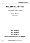
MANUAL PAGE ORGANIZATION
In this manual, pages are organized and the symbols are used as shown below.
The following illustration is for explanation purpose only, and should not be referred to as an actual documentation.
"" is used for
screen names and items.
The chapter of
the current page is shown.
shows operating
procedures.
shows mouse
operations.*1
[ ] is used for items
in the menu bar and
the project window.
The section of
the current page is shown.
Ex. shows setting or
operating examples.
shows reference
manuals.
shows notes that
requires attention.
shows
reference pages.
shows useful
information.
*1
The mouse operation example is provided below.
Menu bar
Ex.
[Online]
[Write to PLC...]
Select [Online] on the menu bar,
and then select [Write to PLC...].
A window selected in the view selection area is displayed.
Ex.
[Parameter]
Project window
[PLC Parameter]
Select [Project] from the view selection
area to open the Project window.
In the Project window, expand [Parameter] and
select [PLC Parameter].
View selection area
12
TERMS
Unless otherwise specified, this manual uses the following terms.
Term
MELSECNET/H remote I/O
module
MELSECNET/10 mode
MELSECNET/H
(MELSECNET/10 mode)
remote I/O station
MELSECNET/H remote I/O
station
Description
A generic term for the QJ72LP25-25, QJ72LP25G, QJ72LP25GE, and QJ72BR15
A mode to use the MELSECNET/H remote I/O module on the MELSECNET/10 remote I/O network
A remote I/O station when the MELSECNET/H remote I/O module has operated in the MELSECNET/10
mode
A remote I/O station with the MELSECNET/H remote I/O module
MELSECNET/10 remote I/O
A generic term for the AJ72LP25, AJ72LP25G, AJ72LR25, AJ72BR15, AJ72QLP25, AJ72QLP25G,
module
AJ72QLR25, AJ72QBR15, A1SJ72QLP25, A1SJ72QLR25, and A1SJ72QBR15
MELSECNET/10 remote I/O
station
Remote I/O module
A remote I/O station with the MELSECNET/10 remote I/O module
A generic term for the MELSECNET/H remote I/O module and MELSECNET/10 remote I/O module
A station which performs the cyclic transmission according to the range assigned at the remote master
Remote I/O station
station.
A generic term for the MELSECNET/H (MELSECNET/10 mode) remote I/O station and MELSECNET/10
remote I/O station
MELSECNET/10 remote
master module
Remote master station
Network module
A generic term for the AJ71LP21, AJ71LP21G, AJ71LR21, AJ71BR11, A1SJ71LP21, A1SJ71LR21,
A1SJ71BR11, AJ71QLP21, AJ71QLP21G, AJ71QLP21S, AJ71QLR21, AJ71QBR11, A1SJ71QLP21,
A1SJ71QLP21S, A1SJ71QLR21, and A1SJ71QBR11
A station where the network parameter for data link is set. A single master station is required on the
MELSECNET/10 remote I/O network.
A generic term for the MELSECNET/10 remote master module, MELSECNET/10 remote I/O module, and
MELSECNET/H remote I/O module
A station that relays the transient transmission to other networks.
Relay station
A station which transfers a link device of a network module to other network modules.
Multiple network modules are mounted on a base unit.
Reserved station
A station reserved for future use. This station is not actually connected, but counted as a connected
station.
GPPA
GPPQ
GX Developer
Product names of the software packages for the MELSEC programmable controllers.
GX Works2
Peripheral
RAS
A generic term for GPPA, GPPQ, and GX Developer used by connecting to the remote master station
An abbreviation for "Reliability", "Availability", and "Serviceability".
This term refers to usability of automated equipment.
A number that specifies the target stations for the transient transmission.
Group number
If the target stations for the transient transmission are specified as a group, data can be sent to the stations
in the same group.
Cyclic transmission
A function that periodically exchanges data between the remote master station and remote I/O stations
using the link device LB, LW, LX, or LY of a network module
Device
A device (X, Y, M, or D) in a CPU module or MELSECNET/H remote I/O module
Transient transmission
requested a link dedicated instruction or peripherals.
A function of communication with a programmable controller in other stations, which is used when
This function can communicate with a programmable controller on the same network and other networks.
Buffer memory
A memory in an intelligent function module and special function module to store data temporary.
The MELSECNET/10 remote master module does not have any buffer memory area that users can use.
13
Term
Baton pass
Link scan time
Link device
Description
A token used to send data to a network
Time required for all stations on a network to transmit data. The link scan time depends on data volume
and the number of transient transmission requests.
A device (LB, LW, LX, or LY) in a network module
In the remote master station, data transfer between a link device in the MELSECNET/10 remote master
Link refresh
module and a device in a CPU module.
Link refresh is performed in the END processing of the CPU module's sequence scan.
Link dedicated instruction
A dedicated instruction is used in the transient transmission.
Disconnection
A process of stopping data link if a data link error occurs
Automatic return
A function that a station disconnected from the data link automatically recovers in the data link when the
station returns normal
A maximum period taken for the following process:
1: The remote I/O station sends data.
2: The remote master station receives the data.
Transmission delay time
3: The data arrive at the operation segment in the CPU module.
In addition, a maximum period taken for the following process:
1: The result of the operation is sent from the CPU module.
2: The remote master station receives the result and sends the result to the remote I/O station.
3: The remote I/O station receives the result.
Return
ZNFR instruction, ZNTO
instruction
A process of restarting data link when a station recovers from an error
A generic term for the ZNFR instruction and ZNTO instruction for the MELSEC-A series remote master
station, and the JP/GP.ZNFR instruction and JP/GP.ZNTO instruction for the MELSEC-QnA series remote
master station
A generic term for the Q03UDVCPU, Q03UDECPU, Q04UDVCPU, Q04UDEHCPU, Q06UDVCPU,
Built-in Ethernet port QCPU
Q06UDEHCPU, Q10UDEHCPU, Q13UDVCPU, Q13UDEHCPU, Q20UDEHCPU, Q26UDVCPU,
Q26UDEHCPU, Q50UDEHCPU, and Q100UDEHCPU
Intelligent function module
High Performance model
QCPU
Process CPU
Basic model QCPU
A MELSEC-Q series module that has functions other than input and output, such as an A/D converter
module and D/A converter module
A generic term for the Q02CPU, Q02HCPU, Q06HCPU, Q12HCPU, and Q25HCPU
A generic term for the Q02PHCPU, Q06PHCPU, Q12PHCPU, and Q25PHCPU
A generic term for the Q00JCPU, Q00CPU, and Q01CPU
A generic term for the Q00UJCPU, Q00UCPU, Q01UCPU, Q02UCPU, Q03UDCPU, Q03UDVCPU,
Q03UDECPU, Q04UDHCPU, Q04UDVCPU, Q04UDEHCPU, Q06UDHCPU, Q06UDVCPU,
Universal model QCPU
Q06UDEHCPU, Q10UDHCPU, Q10UDEHCPU, Q13UDHCPU, Q13UDVCPU, Q13UDEHCPU,
Q20UDHCPU, Q20UDEHCPU, Q26UDHCPU, Q26UDVCPU, Q26UDEHCPU, Q50UDEHCPU, and
Q100UDEHCPU
Special function module
Redundant CPU
14
A MELSEC-A/QnA series module that has functions other than input and output, such as an A/D converter
module and D/A converter module
A generic term for the Q12PRHCPU and Q25PRHCPU
PACKING LIST
The following items are included in the package of this product. Before use, check that all the items are included.
(1) QJ72LP25-25
Product name
Quantity
QJ72LP25-25
1
Before Using the Product
1
(2) QJ72LP25G
Product name
Quantity
QJ72LP25G
1
Before Using the Product
1
(3) QJ72LP25GE
Product name
Quantity
QJ72LP25GE
1
Before Using the Product
1
(4) QJ72BR15
Product name
Quantity
QJ72BR15
1
F-type connector (A6RCON-F)
1
Before Using the Product
1
15
CHAPTER 1
OVERVIEW
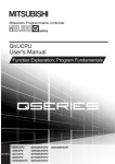
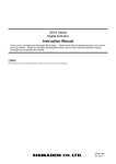
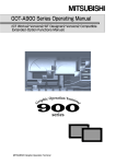
Use of a MELSECNET/H remote I/O module in MELSECNET/10 mode enables a replacement of a MELSECNET/10
remote I/O station with a MELSECNET/H (MELSECNET/10 mode) remote I/O station.
MELSECNET/H remote I/O module
MELSECNET/10
remote I/O network
A module can
be replaced!
1.1
Reference Manuals
For using a MELSECNET/H remote I/O module in MELSECNET/10 mode, refer to the following manuals according to
the purpose.
For details on each manual such as the manual numbers, refer to the following.
RELEVANT MANUALS
No.
1)
Manual name
This manual
2)
QCPU User's Manual (Hardware Design, Maintenance and Inspection)
3)
Q Corresponding MELSECNET/H Network System Reference Manual (Remote I/O network)
4)
Type MELSECNET/10 Network System (Remote I/O network) Reference Manual
5)
For QnA/Q4AR MELSECNET/10 Network System Reference Manual
Transition from MELSEC-A/QnA (Large Type) Series to Q Series Handbook (Fundamentals)
Transition from MELSEC-A/QnA (Large Type) Series to Q Series Handbook (Intelligent Function Modules)
6)
Transition from MELSEC-A/QnA (Large Type), AnS/QnAS (Small Type) Series to Q Series Handbook
(Communications)
Transition from MELSEC-AnS/QnAS (Small Type) Series to Q Series Handbook (Fundamentals)
Transition from MELSEC-AnS/QnAS (Small Type) Series to Q Series Handbook (Intelligent Function Modules)
16
CHAPTER 1 OVERVIEW
Purpose
Manual
1)
2)
3)
4)
5)
1
6)
■System configuration
Overall system configuration of MELSECNET/10
Applicable systems for the MELSECNET/H remote I/O module
Selecting models in the replacement
■Specifications and functions
Specifications
Availability of the functions of the MELSECNET/10 remote I/O network
Availability of the functions of the MELSECNET/H remote I/O module
Details on the functions of the MELSECNET/10 remote I/O network
Details on the functions of the MELSECNET/H remote I/O module
■Procedure before operation
Procedure before operation
Part names of the MELSECNET/H remote I/O module
Mounting and removing a module
Connecting cables
Unit tests of the MELSECNET/H remote I/O module
Offline test in a remote master station
■Parameter setting
Parameter setting for a remote master station
Parameter setting for the MELSECNET/H (MELSECNET/10 mode)
remote I/O station
■Programming
1.1 Reference Manuals
Replacing the existing remote I/O station
■Troubleshooting
Procedure for troubleshooting
Checking troubles on the remote master station
Checking troubles on the MELSECNET/10 remote I/O station
Checking troubles on the MELSECNET/H (MELSECNET/10 mode)
remote I/O station
■Error code
Error codes for the MELSECNET/10 remote I/O network
Error codes equivalent to those of a CPU module detected on the
MELSECNET/H (MELSECNET/10 mode) remote I/O station
■Others
Link special relay (SB), and link special register (SW)
Special relay (SM) for the MELSECNET/H (MELSECNET/10 mode)
remote I/O station, and special register (SD) for the MELSECNET/H
(MELSECNET/10 mode) remote I/O station
17
1.2
Abbreviations Used in the Text, Tables, and Figures
Remote master station
MELSECNET/10
remote I/O station
1)
2)
MELSECNET/10 remote I/O network
3)
MELSECNET/H
(MELSECNET/10 mode)
remote I/O station
No.
18
Name
1)
MELSECNET/10 remote master module
2)
MELSECNET/10 remote I/O module
3)
MELSECNET/H remote I/O module
1)+2)+3)
Network module
CHAPTER 2 SYSTEM CONFIGURATION
CHAPTER 2
2.1
SYSTEM CONFIGURATION
2
Overall System Configuration
This section describes a system configuration where the MELSECNET/H remote I/O module is used in
MELSECNET/10 mode.
In optical loop systems and coaxial bus systems (except parallel master systems), the MELSECNET/H remote I/O
module (MELSECNET/10 mode) can be used in the same system configuration for the MELSECNET/10 remote I/O
module.
No coaxial loop system or parallel master system can be configured when the MELSECNET/H remote I/O module is
used in MELSECNET/10 mode. Consider a different system configuration referring to the following table.
: Configurable ×: Not configurable
System
Configurability
Remarks
Optical loop system
Multiple master system
Parallel master system
×
The system needs to be separated.
Redundant system using the
Q4ARCPU
Coaxial bus system
Multiple master system
Parallel master system
×
The system needs to be separated.
Q4ARCPU
Coaxial loop system
2.2
2.1 Overall System Configuration
Redundant system using the
×
Consider replacing the system with a coaxial bus system.
Applicable System
This section describes the applicable system of the MELSECNET/H (MELSECNET/10 mode) remote I/O station.
(1) Compatible MELSECNET/H remote I/O module
The MELSECNET/H remote I/O module with a serial number (first five digits) of "15012" or later can be used in
MELSECNET/10 mode.
(2) Compatible software package
GX Developer or GX Works2 of the following version can be used for the MELSECNET/H remote I/O module.
Software package
Supported version
GX Developer
Version 6 or later
GX Works2
Version 1.40S or later
19
(3) Mountable main base unit, mountable power supply module, number of
mountable modules
Mount the MELSECNET/H remote I/O module on the CPU slot of a main base unit.
Main base unit
Q33B, Q35B, Q38B, Q312B
Q35BL, Q38BL
(Q series large type main base unit)
Q35BLS, Q35BLS-D, Q38BLS, Q38BLS-D
(Q series large type main base unit (AnS series size))
Q32SB, Q33SB, Q35SB
(Slim type main base unit)
Q35DB, Q38DB, Q312DB
(Multiple CPU high-speed main base unit)
Q38RB
(Main base unit for redundant power supply system)
Power
Number of mountable
supply
MELSECNET/H remote
module
I/O modules
Remarks
Q6P
Q6P
Q6P
Mountable only
1
Q61SP
on the CPU slot
Q6P
Q63RP, Q64RP
(4) Applicable extension base unit
The system including the MELSECNET/H remote I/O module can be extended using extension base units.
Extension cable*2
Extension base unit
Number of
(Overall cable distance:
extension
13.2m or less)
base units
Q63B, Q65B, Q68B, Q612B
(Extension base unit (type requiring a power supply module))
Q52B, Q55B
(Extension base unit (type requiring no power supply module))*1
Q65BL, Q68BL
(Q series large type extension base unit (type requiring a power
supply module))
Q55BL
(Q series large type extension base unit (type requiring no power
QC05B, QC06B, QC12B,
supply module))*1
QC30B, QC50B, QC100B
Max. 7
Q65BLS, Q65BLS-D, Q68BLS, Q68BLS-D
(Q series large type extension base unit (AnS series size) (type
requiring a power supply module))
Q55BLS, Q55BLS-D
(Q series large type extension base unit (AnS series size) (type
requiring no power supply module))*1
Q68RB
(Extension base unit for redundant power supply system)
*1
Calculate the operating voltage of the extension base unit used and check that the voltage is within the rating.
• For the calculation formula, refer to the QCPU User's Manual (Hardware Design, Maintenance and Inspection).
• For the current consumption of each module mounted on the extension base unit, refer to the manual for each
module used.
*2
When using extension cables, pay attention to the following.
• Do not install extension cables together with the main circuit lines (high voltage and large current).
• Connect a cable between the OUT connector of an extension base unit and the IN connector of the next-level
extension base unit.
20
CHAPTER 2 SYSTEM CONFIGURATION
(5) Applicable modules
The MELSEC-Q series modules can be used with the MELSECNET/H remote I/O module. Note that some
modules have restrictions.
2
(a) Functional restrictions
The use of interrupt pointers and dedicated instructions for intelligent function modules are not supported.
(b) Number of mountable modules
Model
Number of mountable modules
QJ71E71-B5, QJ71E71-B2, QJ71E71-100, QJ71E71
Max. 4
QJ61BT11N, QJ61BT11
Max. 4
Modules other than above
Max. 64
(c) Modules with restrictions
Model
Restrictions
• Only the function version B or later can
QJ71E71-B5, QJ71E71-B2, QJ71E71-100, QJ71E71
be used.
• The e-mail function is not supported.
(6) Units/modules not applicable
The following units/modules cannot be used on the MELSECNET/H (MELSECNET/10 mode) remote I/O station.
Module/Unit
Model
Q65WRB
A/AnS series extension base unit
QA1S65B, QA1S68B, QA65B, QA68B
CC-Link IE Controller Network module
QJ71GP21-SX, QJ71GP21S-SX
CC-Link IE Field Network master/local module
QJ71GF11-T2
MELSECNET/H network module
QJ71LP21, QJ71LP21GE, QJ71LP21-25, QJ71LP21S-25,
QJ71LP21G, QJ71BR11, QJ71NT11B
Web server module
QJ71WS96
MES interface module
QJ71MES96
AS-i master module
QJ71AS92
High speed data logger module
QD81DL96
Interrupt module
QI60, QX40H*1, QX70H*1, QX80H*1, QX90H*1
*1
2.2 Applicable System
Redundant type extension base unit
These modules cannot be used when switched to interrupt modules by turning off the function selecting switch (SW2).
(7) ERR. contact of power supply module
The operation of the ERR. contact of a power supply module differs depending on the combination with the base
unit used. For the operation of the ERR. contact, refer to the following.
QCPU User's Manual (Hardware Design, Maintenance and Inspection)
21
(8) Online module change
In the following cases, the online module change cannot be performed.
• When an extension base unit (type requiring no power supply module) (Q52B, Q55B, Q55BL, Q55BLS, or
Q55BLS-D) is used (No module mounted on any extension base unit can be changed online.)
• When a slim type power supply module (Q61SP) is used
(9) Precautions for mounting intelligent function modules
(a) Intelligent function module parameter
When the MELSECNET/H remote I/O module is used in MELSECNET/10 mode, there are some restrictions on
the intelligent function module parameter setting.
• Up to 512 initial setting parameters can be set. If the number of parameters set exceeds the limit, the
MELSECNET/H remote I/O module detects "SP.PARA ERROR" (error code: 3301).
• The auto refresh function is not supported. Access the buffer memory using the ZNFR and ZNTO
instructions.
(b) Network parameter
The CC-Link refresh parameter is not supported. Access the buffer memory using the ZNFR and ZNTO
instructions.
22
CHAPTER 3 SPECIFICATIONS
CHAPTER 3
SPECIFICATIONS
This chapter describes the performance specifications and functions of the network system.
For general specifications, refer to the user's manual for the CPU module used.
3
3.1
Performance Specifications
The following table lists the performance specifications of the MELSECNET/H remote I/O module when it is used in
MELSECNET/10 mode.
Optical loop system
Item
QJ72LP25-25
Coaxial bus system
QJ72LP25G
QJ72LP25GE
Maximum
LX/LY
8192 points
number of
LB
8192 points
LW
8192 points
link points
per network
Maximum number of
link points per station
Remote master station Remote I/O station ((LY + LB) 8 + (2 × LW)) 1600 bytes*1
Remote I/O station Remote master station ((LY + LB) 8 + (2 × LW)) 1600 bytes
Multiplexed remote master station ↔ Multiplexed remote sub-master station ((LY + LB) 8 + (2 × LW)) 2000 bytes
Maximum number of
I/O points per remote
I/O station
X + Y 4096 points
When the numbers of X and Y are overlapped, the number of either X or Y is used for the above formula.
M
8192 points
device points SM
2048 points
per remote
D
12288 points
I/O station
SD
2048 points
Communication speed
10Mbps (20Mbps equivalent in multiplex transmission)
Number of connected
65 stations
stations per network
10Mbps
33 stations
(Remote master station: 1, remote I/O station: 64)*2
(Remote master station: 1,
remote I/O station: 32)*3
3C-2V: 300m
5C-2V: 500m
5C-FB: 500m
Overall cable distance
30km
Can be extended by 2.5km
when the repeater module
(A6BR10 or A6BR10-DC) is
used.
SI optical cable: 500m
Station-tostation
distance
At
10Mbps
H-PCF optical cable: 1km
Broadband H-PCF optical
cable: 1km
GI-50/125
GI-62.5/125
optical cable: 2km
optical cable: 2km
3C-2V: 300m*4
5C-2V: 500m*4
5C-FB: 500m*4
QSI optical cable: 1km
Connection cable
Optical fiber cable (obtained by user)*5
Coaxial cable
(obtained by user)
Connector plug for 3C-2V
Applicable connector
Two-core optical connector plug (obtained by user)
Connector plug for 5C-2V
F06/F08 or equivalent (JIS C5975/5977 compliant)
Connector plug for 5C-FB
(obtained by user)
23
3.1 Performance Specifications
Number of
QJ72BR15
Optical loop system
Item
QJ72LP25-25
Coaxial bus system
QJ72LP25G
Max. number of
QJ72LP25GE
QJ72BR15
239
networks
Network topology
Duplex loop
Single layer bus
Token ring
Token bus
Communication
method
Synchronization
Frame synchronization method
method
Encoding method
NRZI (Non Return to Zero Inverted) code
Transmission format
Manchester code
HDCL standards (frame format)
Error control system
CRC
(X16
+ X12 + X5 + 1) and retry caused by timeout
• Loopback function to be executed upon error detection or cable disconnection (optical loop system only)
• Station cutoff function to be executed upon error detection or cable disconnection (coaxial bus system only)
• Diagnostic function that checks the link line of the host station
RAS function
• Error detection with the link special relay and link special register
• Redundant power supply for a remote I/O station
• Online module change on a remote I/O station
Application function
Remote password for a remote I/O station
Transient transmission
Internal current
consumption (5VDC)
External
dimensions
• ZNFR instruction, ZNTO instruction, JP/GP.ZNFR instruction, JP/GP.ZNTO instruction
0.89A
1.10A
H
98mm
W
27.4mm
D
90mm
Weight
0.15kg
*1
*2
*3
*4
0.16kg
The remote master station includes both the multiplexed remote master station and the multiplexed remote sub-master
station.
Use one of 64 remote I/O stations as a multiplexed remote sub-master station in the multiplexed remote I/O network.
Use one of 32 remote I/O stations as a multiplexed remote sub-master station in the multiplexed remote I/O network.
When the coaxial bus system is used, the cable length between stations is limited depending on the number of
connected stations.
(
*5
Reference manual for the MELSECNET/10 network system used)
SI optical fiber cables (former type: A-2P-) take different station-to-station distances according to the type (L or H
type).
(
24
• 1: 1 communication (such as monitoring and program upload or download)
Reference manual for the MELSECNET/10 network system used)
CHAPTER 3 SPECIFICATIONS
3.2
Function List
3.2.1
Function list of the MELSECNET/10 remote I/O network
The following table lists availability of each function of the MELSECNET/10 remote I/O network on the MELSECNET/H
(MELSECNET/10 mode) remote I/O station.
3
For details on the functions, refer to the following.
Reference manual for the MELSECNET/10 network system used
:
Supported on both the MELSECNET/H (MELSECNET/10 mode) remote I/O station and the MELSECNET/10 remote I/O
station
:
Supported on the MELSECNET/H (MELSECNET/10 mode) remote I/O station, although some specifications differ from
the MELSECNET/10 remote I/O station
×:
Not supported on the MELSECNET/H (MELSECNET/10 mode) remote I/O station
Function
Description
Communications with I/O
Enables communications with I/O modules using the LX/LY
modules
devices.
Communications with special
Enables communications with special function modules
function modules
using the LX/LY and LB/LW devices.
Availability
Stops or restarts cyclic transmission by performing a
network test using a peripheral.
<Difference in comparison with the MELSECNET/10 remote
Stopping/restarting cyclic
function
transmission
transmission
This function is performed using GX Developer on the
MELSECNET/H (MELSECNET/10 mode) remote I/O
3.2 Function List
3.2.1 Function list of the MELSECNET/10 remote I/O network
Basic
Cyclic
I/O station>
station.
function
For details, refer to the following.
Q Corresponding MELSECNET/H Network System
Reference Manual (Remote I/O network)
Reads/writes link devices directly from/to a sequence
Direct access to link devices
program regardless of the link refresh status of the CPU
module. Link devices not set in the link refresh range in
network refresh parameter can be also read/written.
Default of the network refresh
parameter
Reduces the number of network refresh parameters set
using a peripheral to a minimum by setting its default values
automatically in the CPU module.
25
Function
Description
Holds or resets the outputs of remote I/O stations when the
CPU module of the remote master station is down.
Output status setting on
remote I/O stations at system
failure due to a master station
error
<Difference in comparison with the MELSECNET/10 remote
I/O station>
The output status at error is set in PLC parameter for the
MELSECNET/H (MELSECNET/10 mode) remote I/O
station using GX Developer.
For details, refer to Page 49, Section 5.1.
Automatically reconnects a disconnected station in the data
Automatic return function
link after the error is cleared and the station is back to
normal.
Loopback function (optical
loop system)
Basic
function
Switches the transmission path when an error occurs in a
transmission path to cut off the error point, and continues
transmission between the normal stations.
Station cutoff function (coaxial
Continues communications between other normal stations
bus system)
even when a connected station is powered off.
Transient transmission
Enables the network modules to continue transient
enabled even at CPU module
transmission even if an error which stops the operation of
error
the CPU module while the system is in operation occurs.
Checks the internal components of a network module.
RAS function
<Difference in comparison with the MELSECNET/10 remote
I/O station>
Hardware test
The following points differ on the MELSECNET/H
(MELSECNET/10 mode) remote I/O station.
• The number set with the mode setting switch
• Error details check methods: using GX Developer or in
the link special register (SW00AC, SW00AD)
For details, refer to Page 42, Section 4.3.3.
Checks the internal circuits including the send/receive
Offline test
circuits of a network module together with the connected
cable.
<Difference in comparison with the MELSECNET/10 remote
Self-loopback
I/O station>
test
The following points differ on the MELSECNET/H
(MELSECNET/10 mode) remote I/O station.
• The number set with the mode setting switch
• Error details check methods: using GX Developer or in
the link special register (SW00AC, SW00AD)
For details, refer to Page 40, Section 4.3.1.
26
Availability
CHAPTER 3 SPECIFICATIONS
Function
Description
Availability
Checks the internal circuits including the send/receive
circuits of the transmission system of a network module.
<Difference in comparison with the MELSECNET/10 remote
Internal selfloopback test
I/O station>
The following points differ on the MELSECNET/H
(MELSECNET/10 mode) remote I/O station.
• The number set with the mode setting switch
3
• Error details check methods: using GX Developer or in
the link special register (SW00AC, SW00AD)
For details, refer to Page 41, Section 4.3.2.
Offline test
Checks the line status of two adjacent stations.
Station-tostation test
This function is not supported on the MELSECNET/H
(MELSECNET/10 mode) remote I/O station. Perform the
×
forward/reverse loop test from the remote master station or
the MELSECNET/10 remote I/O station instead of this test.
Checks the wiring status of the forward loop and reverse
loop after all stations are connected to the system.
Forward/reverse
This function is not supported on the MELSECNET/H
loop test
(MELSECNET/10 mode) remote I/O station. Perform the
×
test from the remote master station or the MELSECNET/10
remote I/O station.
Checks the line status (forward loop or reverse loop) after
all stations are connected to the optical loop system.
<Difference in comparison with the MELSECNET/10 remote
Loop test
Basic
This function is performed using GX Developer on the
RAS function
MELSECNET/H (MELSECNET/10 mode) remote I/O
station.
3.2 Function List
3.2.1 Function list of the MELSECNET/10 remote I/O network
function
I/O station>
For details, refer to Page 44, Section 4.4.1.
Checks the switch setting of a network module.
<Difference in comparison with the MELSECNET/10 remote
Setup
I/O station>
confirmation test
This function is performed using GX Developer on the
MELSECNET/H (MELSECNET/10 mode) remote I/O
station.
For details, refer to Page 45, Section 4.4.2.
Online
Checks the order of connected stations in the optical loop
diagnostics
system.
Station order
check test
<Difference in comparison with the MELSECNET/10 remote
I/O station>
This function is performed using GX Developer on the
MELSECNET/H (MELSECNET/10 mode) remote I/O
station.
For details, refer to Page 46, Section 4.4.3.
Checks whether transient transmission is normally
performed.
Communication
test
<Difference in comparison with the MELSECNET/10 remote
I/O station>
This function is performed using GX Developer on the
MELSECNET/H (MELSECNET/10 mode) remote I/O
station.
For details, refer to Page 47, Section 4.4.4.
27
Function
Description
Checks the information of an entire network and the status
of the host station.
<Difference in comparison with the MELSECNET/10 remote
Host information
I/O station>
This function is performed using GX Developer on the
MELSECNET/H (MELSECNET/10 mode) remote I/O
station.
For details, refer to Page 75, Section 7.2.1.
Checks the status of communications, data link,
parameters, CPU modules, and loops of other stations
(including reserved stations).
<Difference in comparison with the MELSECNET/10 remote
Other station
information
I/O station>
The following points differ on the MELSECNET/H
(MELSECNET/10 mode) remote I/O station.
• When monitoring from a peripheral, GX Developer shall
be used.
• The parameter status of each station cannot be
monitored. Monitor them from the remote master station.
Network
For details, refer to Page 77, Section 7.2.2.
monitor
Checks the status of the network line connected to a
peripheral, data link, CPU module, and parameters.
Basic
function
RAS function
Network monitor
details
<Difference in comparison with the MELSECNET/10 remote
I/O station>
This function is performed using GX Developer on the
MELSECNET/H (MELSECNET/10 mode) remote I/O
station.
For details, refer to Page 78, Section 7.2.3.
Checks the history of forward/reverse loop errors,
communication errors, and transient transmission errors.
The details of the error history can be displayed and the
error history can be cleared.
Error history
monitor
<Difference in comparison with the MELSECNET/10 remote
I/O station>
This function is performed using GX Developer on the
MELSECNET/H (MELSECNET/10 mode) remote I/O
station.
For details, refer to Page 81, Section 7.2.4.
Monitors the data link status using a peripheral.
<Difference in comparison with the MELSECNET/10 remote
Data link status detection
I/O station>
function
This function is performed using GX Developer on the
MELSECNET/H (MELSECNET/10 mode) remote I/O
station.
For details, refer to Page 77, Section 7.2.2.
28
Availability
CHAPTER 3 SPECIFICATIONS
Function
Description
Availability
Disables the detection of a fuse blown error or I/O module
verification error by the remote I/O station.
<Difference in comparison with the MELSECNET/10 remote
I/O station>
Basic
function
RAS function
Fuse blown error/I/O module
The disabled status can also be set in PLC parameter for
verify error check disable
the MELSECNET/H (MELSECNET/10 mode) remote I/O
function
station using GX Developer.
3
Note that, however, if the error clear (disabled) status is set
on the remote master station, the module operates with the
setting of the remote master station regardless of the setting
on the MELSECNET/H (MELSECNET/10 mode) remote I/O
station. For details, refer to Page 49, Section 5.1.
Routing function
Enables transient transmission to a station with another
network number in a multilevel system.
A dedicated instruction (ZNFR, ZNTO, JP/GP.ZNFR, and
Link dedicated instruction
JP/GP.ZNTO) to read/write data from/to the buffer memory
of special function modules mounted on the remote I/O
station from the remote master station
Enables communications with the network that is set in
Transient
Default network specification
transmission
parameter ("Valid module during other station access") by
specifying "254 (00FEH)" for the network number of the
access-target special function module.
function
Sets clock data (date and time) to stations in a network
using a peripheral.
Clock data shall be set to the CPU module on the remote
Clock setting of stations in a
master station.
network
(Only the QnA corresponding MELSECNET/10 network
module supports this function.)
3.2 Function List
3.2.1 Function list of the MELSECNET/10 remote I/O network
The clock data set in the CPU module is transferred to
remote I/O stations.
Application
function
Multiplex transmission function (optical loop
system)
Number of return stations setting
Enables high-speed communications using a duplex
transmission path (forward loop and reverse loop) of the
optical loop system.
Sets the number of communication error stations that can
go back to the data link within one link scan.
Treats a station that will be connected in the future as a
Reserved station function
reserved station, not as a communication error station. (The
station is included in the total number of connected stations,
but actually not connected.)
Assigns I/O points to I/O modules and special function
modules mounted on the remote I/O station.
<Difference in comparison with the MELSECNET/10 remote
I/O station>
I/O points can also be set in PLC parameter for the
I/O assignment
MELSECNET/H (MELSECNET/10 mode) remote I/O
station using GX Developer.
Note that, however, if I/O points are assigned to the remote
master station, the module operates with the assignment
set to the remote master station regardless of the setting on
the MELSECNET/H (MELSECNET/10 mode) remote I/O
station. For details, refer to Page 49, Section 5.1.
29
Function
Multiple
master
system
Description
Simplex network
The multiplexed remote master function for simplex network
Duplex network
The multiplexed remote master function for duplex network
Availability
A system that allows the parallel remote master station and
parallel remote sub-master station to control each remote
I/O station separately. (Only the QnA corresponding
Application
Parallel master system
MELSECNET/10 network module supports this function.)
Since this system is not supported on the MELSECNET/H
function
(MELSECNET/10 mode) remote I/O station, the system
needs to be separated.
Prevents the change of the link scan time caused by the
Constant link scan
transient transmission function or noise, and keeps the link
scan time constant.
30
Number of ZNFR/ZNTO accesses setting
Sets the number of modules to which a remote I/O station
function
can execute instructions in one scan.
×
CHAPTER 3 SPECIFICATIONS
3.2.2
Function list of the MELSECNET/H remote I/O module
The following table lists availability of each function of the MELSECNET/H remote I/O module when it is used in
MELSECNET/10 mode.
For details on the functions, refer to the following.
Q Corresponding MELSECNET/H Network System Reference Manual (Remote I/O network)
: Supported in MELSECNET/10 mode
3
×: Not supported in MELSECNET/10 mode
Function
Cyclic
transmission
function
(periodic
communication)
Basic
function
RAS function
Application
function
Communications with I/O modules
Enables communications with I/O modules using the LX/LY devices.
Communications with intelligent
function modules
Refreshes the data in intelligent function modules into the devices of
the MELSECNET/H remote I/O module.
Output reset function for
communication error
Turns off all outputs of the MELSECNET/H remote I/O station when
a data link error occurs.
Hardware error time CPU
operation mode setting
Determines whether the operation of the MELSECNET/H remote I/O
station stops or continues when a hardware error occurs in an
intelligent function module mounted on the MELSECNET/H remote
I/O station.
Diagnostic function
Checks the status of network lines and module settings.
Redundant power supply on a
remote I/O station
Configures a redundant power supply system by mounting two
power supply modules on a redundant power supply base unit.
Online module change on a
remote I/O station
Changes the MELSEC-Q series modules mounted on the main base
unit or extension base units of the MELSECNET/H remote I/O
station during online.
Intelligent function module buffer
memory read/write
(REMFR/REMTO)
Dedicated instructions to read/write data from/to the buffer memory
of intelligent function modules mounted on the MELSECNET/H
remote I/O station.
Use the ZNFR and ZNTO instructions to access intelligent function
modules on the MELSECNET/H (MELSECNET/10 mode) remote
I/O station as well as the MELSECNET/10 remote I/O network.
*1
×
(
Reference manual for the MELSECNET/10 network system
used)
Remote I/O station system monitor
Performs a system monitor on intelligent function modules mounted
on the MELSECNET/H remote I/O station using GX Developer.
Device test for a remote I/O station
Tests I/O devices in a sequence program without stopping the online
system using GX Developer connected with the MELSECNET/H
remote I/O station.
I/O assignment
Assigns I/O points to I/O modules and intelligent function modules
mounted on the MELSECNET/H remote I/O station.
Remote password
Prevents unauthorized access to the MELSECNET/H remote I/O
module and the CPU module by remote users.
*1
Availability
3.2 Function List
3.2.2 Function list of the MELSECNET/H remote I/O module
Transient
transmission
function (nonperiodic
communication)
Description
*2
The following functions are not supported.
• Auto refresh function of intelligent function modules
• CC-Link refresh parameter
• Data transfer between devices
*2
The modules cannot be monitored via the remote master station.
31
3.2.3
Link data send/receive processing time
This section describes the link data send/receive processing time of the MELSECNET/H remote I/O module when it is
used in MELSECNET/10 mode.
(1) Remote master station ↔ Remote I/O station
(a) Cyclic transmission (X/Y communication)
The same performance as that of the MELSECNET/10 remote I/O station is provided.
For details on the transmission delay time of the cyclic transmission (X/Y communication), refer to the
following.
Reference manual for the MELSECNET/10 network system used
(b) ZNFR instruction, ZNTO instruction
The same performance as that of the MELSECNET/10 remote I/O station is provided.
For the transmission delay time of ZNFR instruction and ZNTO instruction, refer to the following.
Reference manual for the MELSECNET/10 network system used
(2) Refresh time between the MELSECNET/H remote I/O module and I/O modules
The same performance as that of the MELSECNET/H remote I/O station is provided.
For the refresh time between the MELSECNET/H remote I/O module and I/O modules, refer to the following.
Q Corresponding MELSECNET/H Network System Reference Manual (Remote I/O network)
(3) Link scan time
The same performance as that of the MELSECNET/10 remote I/O station is provided.
For the link scan time, refer to the following.
Reference manual for the MELSECNET/10 network system used
32
CHAPTER 4 SETTING AND PROCEDURE BEFORE OPERATION
CHAPTER 4
SETTING AND PROCEDURE
BEFORE OPERATION
This chapter describes the setting and procedure before operation.
4.1
Procedure Before Operation
4
The following is the procedure for replacing a MELSECNET/10 remote I/O station with a MELSECNET/H
(MELSECNET/10 mode) remote I/O station.
Checking the system configuration
Check the configuration of the MELSECNET/10 remote I/O network.
If a coaxial loop system or parallel master system is configured, the system cannot be replaced.
Consider a different system configuration.
(
Page 19, Section 2.1)
Checking the target station for the replacement
Check the system configuration of the MELSECNET/10 remote I/O station targeted for the replacement.
Considering an installation location
Consider an installation location paying attention to the following points.
• Length of communication cables
• Length of power distribution lines
• Length of external wires
4.1 Procedure Before Operation
Selecting modules used after the replacement
Handbook for transition
Select modules to be mounted on the MELSECNET/H (MELSECNET/10 mode) remote I/O station after the
replacement.
Checking the program
Modification of the sequence program may be required after the replacement.
Check the parts in the sequence program where modification is required.
(
Page 53, Section 6.1)
(
Page 37, Section 4.2 (3))
Stopping the system
Stop the MELSECNET/10 remote I/O network and all relayed network systems including all external devices
safely.
Setting the station number of the MELSECNET/H remote I/O module
Set the station number with the station number setting switches on the MELSECNET/H remote I/O module.
Replacing the remote I/O station
Replace the MELSECNET/10 remote I/O station with the MELSECNET/H (MELSECNET/10 mode) remote I/O
station.
Preparation before power-on
Move the RUN/STOP switch of the CPU module on the remote master station to the STOP position.
Check the wiring of the voltage input from power supply.
33
Powering on
Power on the MELSECNET/H (MELSECNET/10 mode) remote I/O station.
Check that the POWER LED of the power supply module and the RUN LED of the MELSECNET/H remote I/O
module are on.
Performing unit tests
Perform the following unit tests on the MELSECNET/H remote I/O module.
• Self-loopback test
• Internal self-loopback test
• Hardware test
(
Page 40, Section 4.3.1)
(
Page 41, Section 4.3.2)
(
Page 42, Section 4.3.3)
(
Page 37, Section 4.2 (4))
(
Page 49, Section 5.1)
Setting the mode setting switch
Set the mode setting switch of the MELSECNET/H remote I/O module to “8”.
Setting parameters of the MELSECNET/H (MELSECNET/10 mode) remote I/O station
Set parameters of the MELSECNET/H (MELSECNET/10 mode) remote I/O station as needed.
After setting parameters, write the parameters to the MELSECNET/H remote I/O module.
• PLC parameter
• Network parameter
• Intelligent function module parameter
Powering off
Power off the MELSECNET/H (MELSECNET/10 mode) remote I/O station.
Connecting cables
Connect cables to the MELSECNET/H (MELSECNET/10 mode) remote I/O station.
Reference manual of the
MELSECNET/10 network system used
Powering on the network
Power on the remote I/O station first and then the remote master station.
Diagnosing the network
Connect a peripheral to the remote master station and perform the following network diagnostics.
• Loop test (optical loop system only)
• Setup confirmation test
• Station order check test (optical loop system only)
• Communication test
(
Page 44, Section 4.4.1)
(
Page 45, Section 4.4.2)
(
Page 46, Section 4.4.3)
(
Page 47, Section 4.4.4)
(
Page 53, Section 6.1)
Checking and modifying the program
Check the sequence program of the CPU module on the remote master station. Modify the program if necessary.
34
CHAPTER 4 SETTING AND PROCEDURE BEFORE OPERATION
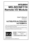
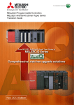
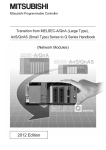
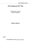
4.2
Part Names and Settings
QJ72LP25-25
RUN
T. PASS
SD
ERR.
REM.
D. LINK
RD
L ERR.
QJ72BR15
QJ72LP25G
RUN
T.PASS
SD
ERR.
(1)
REM.
D.LINK
RD
L ERR.
RUN
T.PASS
SD
ERR.
(1)
RS-232
RS-232
REM.
D.LINK
RD
L ERR.
(1)
RS-232
(2)
(2)
(2)
STATION
NO.
x 10
(3)
R-SD
(5)
IN
x1
(5)
IN
RESET
F-RD
(4)
RESET
(4)
(3)
(Left side surface)
MODE
(6)
OUT
(5)
STATION NO.
(4)
(3)
(Left side surface)
x 10
F-SD
(5)
OUT
x1
(5)
(6)
STATION NO.
QJ72LP25-25
(6)
MODE
RESET
MODE
R-RD
x 10
x1
4
QJ72BR15
QJ72LP25G
(7)
(7)
(7)
(1) LED indications
Name
REM.*1
On (green)
Normal operation
Off
Watchdog timer error (hardware failure)
On (green)
Normal operation
Flashing (green)
Off
On (green)
T.PASS
D.LINK
SD
RD
Description
Flashing (green)
Parameters being written to the flash ROM or forced input/output being registered
Being initialized remotely or error (watchdog timer error, fuse blown error, I/O module verify
error, or other errors)
In the baton pass status (The module is connected to the network.)
Being tested (When the LED flashes 20 times or more (approx. 10 seconds), it means the end
of the test.)
Off
Not in the baton pass status (The host station has been disconnected from the network.)
On (green)
Data link being performed (Cyclic transmission is being performed.)
Off
Data link not being performed (Parameters have not been received, an error has occurred in
the CPU module of host station, a data link stop instruction has been issued, or others.)
On (green)
Data being sent
Off
Data not being sent
On (green)
Data being received
Off
Data not being received
35
4.2 Part Names and Settings
RUN
LED status
Name
LED status
Description
• Station number setting error (other than 1 to 64), mode setting error (set to disabled), or
operating condition setting error (in parameter)
On (red)
• A station with the same station number exists in the network.
• Parameter data received from the remote master station has an error.
ERR.
• Watchdog timer error (The RUN LED is off.)
*1
• An error is detected at the test operation of the MELSECNET/H remote I/O module.
Flashing
• The setting of the mode setting switch or station number setting switches has been changed
during the operation.
Off
Normal operation
Watchdog timer error (The RUN LED is off.)
Communication error (One of the following errors has been occurred.)
• CRC
This error occurs due to a fault in the cable or noise.
• OVER
This error occurs when the received data is erased before it is written to the internal memory
because the next data is received. The possible error cause is a hardware failure at the
receiver part of the MELSECNET/H remote I/O module.
• AB.IF
This error occurs when the number of the bits indicating "1" in the received data within a
frame exceeds the limit or the received data length is shorter than that defined in the
specifications.
• TIME
On (red)
L ERR.
This error occurs when the baton pass is not handed to the host station within the monitoring
time.
• DATA
This error occurs when the data with abnormal code is received.
• UNDER
This error occurs when the internal processing of send data is not performed at a fixed
interval.
• LOOP
This error occurs when the forward loop or reverse loop line is faulty. The power of the
adjacent station in the direction to the host station is off or the hardware failure exists on the
send station.
<Action>
Check the connector for disconnection, looseness, and IN/OUT misconnection; and the cable
for disconnection, crack, and routing.
• For details, refer to the network diagnostics. (
Off
*1
Page 75, Section 7.2)
No communication error
When the MELSECNET/H remote I/O module is used in a redundant power supply system, the cause of failure in the
power supply module can be diagnosed with the status of the REM. LED and ERR. LED.
Power supply
module
Cause of failure
Input power supply OFF, fuse blown
Failure of one module
Internal failure
Input power supply OFF, fuse blown
Failure of both modules
Internal failure
REM. LED
ERR. LED
Off
On
Off
On
On
Off
Off
Off
Off
Off
Off
On
On
Off
The faulty power supply module can be identified in the corresponding error code. (
Page 93, Section 7.4.3)
Check the failure status of the power supply module with the LEDs of the module. When the power supply module is
mounted on an extension base unit, the failure status can also be checked with the ERR. contact of the module.
(
36
QCPU User's Manual (Hardware Design, Maintenance and Inspection))
CHAPTER 4 SETTING AND PROCEDURE BEFORE OPERATION
(2) RS-232 connector
A connector is connected with RS-232.
This connector can be connected with the RS-232 connection cable (QC30R2).
(3) Station number setting switches
Set a station number of the MELSECNET/H remote I/O module in a network. (Factory default: 1)
4
10 10s unit
1
Setting
0
1s unit
Description
Setting error
LED indication
The ERR.LED turns on (red).
Effective setting range
1 to 64
(When the QJ72BR15 is used, the numbers from
33 to 64 cause a setting error.)
65 to 99
Setting error
The ERR.LED turns on (red).
● Station numbers within a network must be unique.
● Station numbers do not need to be in order. When not setting a station number, set the station as a reserved station.
4.2 Part Names and Settings
(4) Mode setting switch
Set the operation mode of the MELSECNET/H remote I/O module. (Factory default: 0)
• QJ72LP25-25
Setting
Description
0
Online
1
Self-loopback test
2
Internal self-loopback test
3
Hardware test
4
Online
5
Self-loopback test
6
Internal self-loopback test
7
Hardware test
8
Online (MELSECNET/10 mode)
9 to F
Communication speed: 10Mbps
Communication speed: 25Mbps
Use prohibited
37
• QJ72LP25G, QJ72LP25GE, QJ72BR15
Setting
Description
0
Online
1
Self-loopback test
2
Internal self-loopback test
3
Hardware test
4 to 7
Use prohibited
8
Online (MELSECNET/10 mode)
9 to F
Use prohibited
(5) Connectors
• QJ72LP25-25, QJ72LP25G, QJ72LP25GE: IN connector, OUT connector
Connect an optical fiber cable connector.
QJ72LP25-25
QJ72LP25G,
QJ72LP25GE
1)
1)
1) IN: Reverse loop sending
2)
2)
2) IN: Forward loop receiving
3) OUT: Forward loop sending
4) OUT: Reverse loop receiving
3)
3)
4)
4)
• QJ72BR15: Coaxial connector
Connect an F-type connector for coaxial cables.
(6) RESET switch
Reset the MELSECNET/H (MELSECNET/10 mode) remote I/O station. Press the switch for one second or longer
to reset. If not, the modules on the station cannot be reset normally. If the modules have not been reset normally,
perform the reset operation again.
(7) Serial number display
The serial number on the rating plate is displayed.
38
CHAPTER 4 SETTING AND PROCEDURE BEFORE OPERATION
4.3
Unit Tests of the MELSECNET/H Remote I/O Module
(Offline Test)
The MELSECNET/H remote I/O module and the connected cable shall be tested before performing the data link.
Select the test item with the mode setting switch on the front of the MELSECNET/H remote I/O module. The following
three items are provided for the offline test.
(1) Self-loopback test (Mode setting switch: 1)
This test checks the internal circuits including the send/receive circuits of the MELSECNET/H remote I/O module
together with the connected cable.
4
(2) Internal self-loopback test (Mode setting switch: 2)
This test checks the internal circuits including the send/receive circuits of the MELSECNET/H remote I/O module.
(3) Hardware test (Mode setting switch: 3)
This test checks the internal components of the MELSECNET/H remote I/O module.
● If the test completes with an error, the possible cause is a hardware failure of the MELSECNET/H remote I/O module.
Please consult your local Mitsubishi representative.
● The station-to-station test is not supported on the MELSECNET/H (MELSECNET/10 mode) remote I/O station. Perform
the forward/reverse loop test from the remote master station or the MELSECNET/10 remote I/O station.
If even one station is set to the test mode (offline, mode setting switch 1 to 3) during the data link (online), the normal data
link cannot be maintained.
39
4.3 Unit Tests of the MELSECNET/H Remote I/O Module (Offline Test)
Remark
4.3.1
Self-loopback test
This test checks the internal circuits including the send/receive circuits of the MELSECNET/H remote I/O module
together with the connected cable.
Always connect a cable or terminating resistors when performing the self-loopback test. In addition, do not connect or
disconnect the cable or terminating resistors during the test. (The test completes with an error.)
For QJ72LP25-25,
QJ72LP25G, QJ72LP25GE
(optical loop system)
1.
For the QJ72LP25-25, QJ72LP25G, and
QJ72LP25GE, connect the IN
For QJ72BR15
(coaxial bus system)
connector and OUT connector by an
optical fiber cable.
For the QJ72BR15, connect
terminating resistors to both
Connect the
IN and OUT
connectors.
connectors of the F-type connector.
Connect
terminating
resistors.
2.
Set the mode setting switch on the
MELSECNET/H remote I/O module to
"1".
3.
Power on the target module. The selfloopback test starts and the T.PASS
Flashing
LED flashes.
4.
The test is completed normally when
the T.PASS LED flashes 20 or more
times (approx. 10 seconds) and the
ERR. LED does not flash. When the
test completes with an error, the ERR.
LED flashes.
If an error occurs, perform the following.
• For the QJ72LP25-25, QJ72LP25G, QJ72LP25GE replace the cable and perform the test again.
• For the QJ72BR15, replace the terminating resistors and perform the test again.
When the test completes with an error again, the possible cause is a hardware failure of the MELSECNET/H remote
I/O module. Please consult your local Mitsubishi representative.
Remark
Check the test condition and error details with the following link special register areas.
• Baton pass status (host) (SW0047) 1FH: Offline test
• Cause of baton pass interruption (SW0048) 2H: Offline test
• Offline test execution item/faulty station (requesting side) (SW00AC) 7H: Self-loopback test
• Offline test result (requesting side) (SW00AD) 0: Normal, 1 and later: Error code
40
CHAPTER 4 SETTING AND PROCEDURE BEFORE OPERATION
4.3.2
Internal self-loopback test
This test checks the internal circuits including the send/receive circuits of the MELSECNET/H remote I/O module
For QJ72LP25-25,
QJ72LP25G, QJ72LP25GE
(optical loop system)
1.
Do not connect an optical fiber cable for the
QJ72LP25-25, QJ72LP25G. and QJ72LP25GE
For QJ72BR15
(coaxial bus system)
Prevent ambient light from entering the
connector.
Avoid ambient
light.
Do not connect a cable or terminating resistor to
Do not connect
anything.
4
the QJ72BR15.
2.
Set the mode setting switch on the
MELSECNET/H remote I/O module to "2".
3.
Power on the target module.
The internal self-loopback test starts and the
T.PASS LED flashes.
Flashing
4.
The test is completed normally when the T.PASS
LED flashes 20 or more times (approx. 10
seconds) and the ERR. LED does not flash.
When the test completes with an error, the ERR.
LED flashes.
Remark
Check the test condition and error details with the following link special register areas.
• Baton pass status (host) (SW0047) 1FH: Offline test
• Cause of baton pass interruption (SW0048) 2H: Offline test
• Offline test execution item/faulty station (requesting side) (SW00AC) 8H: Internal self-loopback test
• Offline test result (requesting side) (SW00AD) 0: Normal, 1 and later: Error code
41
4.3 Unit Tests of the MELSECNET/H Remote I/O Module (Offline Test)
4.3.2 Internal self-loopback test
When the test completes with an error, the possible cause is a hardware failure of the MELSECNET/H remote I/O
module. Please consult your local Mitsubishi representative.
4.3.3
Hardware test
This test checks the internal components of the MELSECNET/H remote I/O module.
For QJ72LP25-25,
QJ72LP25G, QJ72LP25GE
(optical loop system)
1.
For the QJ72LP25-25, QJ72LP25G, and
QJ72LP25GE connect the IN connector and OUT
For QJ72BR15
(coaxial bus system)
connector by an optical fiber cable.
Do not connect a cable or terminating resistor to
Connect the
IN and OUT
connectors.
the QJ72BR15.
Do not connect
anything.
2.
Set the mode setting switch on the
MELSECNET/H remote I/O module to "3".
MODE
3
3.
Power on the target module.
The hardware test starts and the T.PASS LED
flashes.
Flashing
4.
The test is completed normally when the T.PASS
LED flashes 20 or more times (approx. 10
seconds) and the ERR. LED does not flash.
When the test completes with an error, the ERR.
LED flashes.
When the test completes with an error, the possible cause is a hardware failure of the MELSECNET/H remote I/O
module. Please consult your local Mitsubishi representative.
Remark
Check the test condition and error details with the following link special register areas.
• Baton pass status (host) (SW0047) 1FH: Offline test
• Cause of baton pass interruption (SW0048) 2H: Offline test
• Offline test execution item/faulty station (requesting side) (SW00AC) 9H: Hardware test
• Offline test result (requesting side) (SW00AD) 0: Normal, 1 and later: Error code
42
CHAPTER 4 SETTING AND PROCEDURE BEFORE OPERATION
4.4
Network Diagnostics (Online Test)
The network diagnostic function enables easy check and diagnostics of the line status. To execute this function, the
network parameters must be set to the remote master station.
To execute the network diagnostic function from the MELSECNET/H (MELSECNET/10 mode) remote I/O station, use
GX Developer or GX Works2. (GPPA and GPPQ cannot be used.)
The following table lists the tests that can be executed in each system.
: Executable ×: Not executable
Data link status
Test item
Optical loop system
Coaxial bus system
4
(cyclic transmission and transient
transmission)
Loop test
×
Setup confirmation test
Station order check test
Communication test
Interrupted temporarily
Interrupted temporarily
×
Interrupted temporarily
Continued
● Perform the network diagnostics that requires a temporarily interruption of the data link at system start-up.
When performing the diagnostics during the system operation, check that the following conditions are met.
• No problem occurs even when the data link stops due to the diagnostics.
• Reset of any station or operating status change (RUN/STOP) or any CPU module is not required. (The change
may cause an error completion of the diagnostics.)
● Perform the setup confirmation test, station order check test, and communication test after checking that the line status is
normal by the loop test.
4.4 Network Diagnostics (Online Test)
43
4.4.1
Loop test (optical loop system only)
This test checks the line status (forward loop or reverse loop) after all stations are connected to the optical loop
system.
Peripheral
Station No.4
Reserved station
Station No.0
Remote master station
IN
OUT
OUT
IN
Station No.1
Loopback
OUT
IN
Station No.3
Faulty station
IN
OUT
IN
OUT
Station No.2
Loopback
When the loop test is performed using a peripheral connected to the remote master station in the system above, where
IN connector and OUT connector of the station number 3 are connected inversely, the following window appears. The
station number 3 is detected as a receive direction faulty station.
● In the loop test, the wiring status is checked after the data link has been stopped.
To check the wiring status without stopping the data link, use SW009C to SW009F of the MELSECNET/H
(MELSECNET/10 mode) remote I/O station.
(
Q Corresponding MELSECNET/H Network System Reference Manual (Remote I/O network))
● During the loopback, stations where the loopback is being performed can be checked in the "Loop status of each station"
window opened from the "Other station information" window. (
44
Page 77, Section 7.2.2)
CHAPTER 4 SETTING AND PROCEDURE BEFORE OPERATION
4.4.2
Setup confirmation test
This test checks the switch setting of a network module.
The station number overlap status can be checked.
Peripheral
Station No.0
Remote master station
Station No.4
Reserved station
4
Station No.1
Station No.
duplication error
Station No.1
Station No.2
Station No.
duplication error
When the setup confirmation test is performed using a peripheral connected to the remote master station in the system
above, the following window appears. The result shows that the station number 1 has a station No. duplication error.
4.4 Network Diagnostics (Online Test)
4.4.2 Setup confirmation test
45
4.4.3
Station order check test (optical loop system only)
This test checks the order of connected stations in the optical loop system.
The following table lists the correspondence between the loop status and the order of stations that can be checked in
the test.
Loop status
Forward/reverse loop
Forward loop
Display contents
The station numbers connected in the forward loop direction from the host station and the station numbers
connected in the reverse loop direction from the host station
Only the station numbers connected in the forward loop direction from the host station
Reverse loop
Only the station numbers connected in the reverse loop direction from the host station
Loopback
Only the station numbers connected in the forward loop direction from the host station
Forward loop direction
Reverse loop direction
Peripheral
Station No.4
Reserved station
Station No.0
Remote master station
IN
OUT
OUT
IN
Station No.1
Loopback
IN
OUT
IN
Station No.3
Faulty station
OUT
OUT
IN
Station No.2
Loopback
When the station order check test is performed using a peripheral connected to the remote master station in the
system above, the following window appears. The result shows that the loopback is performed in the stations, the
station number 2 and 1, connected in the forward loop direction.
The station No.4 is
not displayed
because it is a
reserved station.
46
CHAPTER 4 SETTING AND PROCEDURE BEFORE OPERATION
4.4.4
Communication test
This test checks whether communications is normally performed between a test-executing station and a
communication-target station (specified with the network number and station number).
If the communication-target station is in another network, the relay network number and station number are displayed
and the routing parameter settings can be checked.
Host Station
station No.1
Network No.1
(PLC to PLC
network)
Station Station
No.2
No.1
Network No.2
(PLC to PLC
network)
Station Station
No.2
No.0
Network No.3
(remote I/O
network)
Station Communication-target
station
No.1
4
When the communication test is performed from a peripheral connected to the station number 1 in network number 1
to the station number 1 in network number 3 in the system above, the following window appears. The result shows that
communications between two stations is normal.
4.4 Network Diagnostics (Online Test)
4.4.4 Communication test
47
The following table lists the availability of the communication test for each station. The communication test cannot be
performed between MELSECNET/H (MELSECNET/10 mode) remote I/O stations.
(1) In the same network
: Supported ×: Not supported
Host station
Destination station
MELSECNET/H (MELSECNET/10 mode)
Remote master station
remote I/O station
MELSECNET/H (MELSECNET/10 mode)
remote I/O station
Remote master station
GPPA
*1
×
GPPQ
*2
×
GX Developer
GX Works2
*3
×
*1
*2
*3
Supported only on the remote master station where the AnUCPU or AnUSCPU is mounted.
Supported only on the remote master station where the QnACPU or QnASCPU is mounted.
Supported only when the communication-target network module is compatible with the QnA series.
(2) In another network
: Supported ×: Not supported
Host station
Destination station
Remote master
Control station/
MELSECNET/H (MELSECNET/10 mode)
station
normal station
remote I/O station
MELSECNET/H (MELSECNET/10 mode)
Remote master
Control station/
remote I/O station
station
normal station
GPPA
*1
*1
×
×
GPPQ
*2
*2
×
×
GX Developer
GX Works2
×
*1
*2
*3
48
×
*3
*3
Supported only on the remote master station, control station, or normal station where the AnUCPU or AnUSCPU is
mounted.
Supported only on the remote master station, control station, or normal station where the QnACPU or QnASCPU is
mounted.
Supported only when the communication-target network module is compatible with the MELSECNET/10 QnA series.
CHAPTER 5 PARAMETER SETTING
CHAPTER 5
PARAMETER SETTING
To operate MELSECNET/10 remote I/O network, network parameters must be set to the CPU module on the remote
master station using a peripheral.
For the parameter setting for the MELSECNET/10 remote master module, refer to the following.
Reference manual for the MELSECNET/10 network system used
5.1
Parameter Setting for Remote I/O Stations
This section describes parameters set to the MELSECNET/H (MELSECNET/10 mode) remote I/O station.
5
To use the MELSEC-Q series functions on the MELSECNET/H (MELSECNET/10 mode) remote I/O station, set
parameters to the MELSECNET/H remote I/O module.
To use the MELSECNET/H (MELSECNET/10 mode) remote I/O station as a remote I/O station equivalent to that for
the MELSEC-A/QnA series, set only intelligent function module switch parameters.
The set parameters are enabled when one of the following is performed.
• Reset the MELSECNET/H remote I/O module.
• Power off and on the MELSECNET/H remote I/O module.
• When the parameters of the remote I/O station are corrected and the remote I/O station has not been reset: Reset
the CPU module on the remote master station, switch the status of the CPU module from STOP to RUN, or power
off and on the programmable controller.
• When a stop error exists on the remote I/O station: Reset the CPU module on the remote master station, switch
the status of the CPU module from STOP to RUN, or power off and on the programmable controller.
The PLC parameter can be set to the MELSECNET/H remote I/O module as well as being set to the CPU
module. The following table lists the setting availability on the MELSECNET/H (MELSECNET/10 mode) remote
I/O station.
For details on the "PLC system", "PLC RAS", and "I/O assignment" parameter settings, refer to the following.
GX Developer Version 8 Operating Manual
Category
PLC system
PLC RAS
(
Item
5.1 (1) (a))
Availability
Synchronize intelligent function module's pulse up
Selected
Available
Points occupied by empty slot
Points occupied by empty slot
16 points
Available
Carry out fuse blown check
Selected
Available*1
Verify module
Selected
Available*1
Available
Error check
Page
50, Section
Default
Module synchronization
Fuse blown
Stop
is an error
Module verify error
Stop
Remote I/O switch setting
Remote I/O switch setting (For future expansion)
Operating mode when there
Assignment method
Operational
Points/Start
Start/End
Start/End
Forwarding parameter
Points
between devices
Start
End
N/A
N/A*2
N/A*2
N/A*3
Device name
settings
Available
Blank
N/A*3
N/A*3
N/A*3
49
5.1 Parameter Setting for Remote I/O Stations
(1) PLC parameter
Category
Item
Default
Type
Available
Model name
I/O
Available
Switch setting
Detailed setting
Page
50, Section
5.1 (1) (b))
Available
StartXY
assignment
(
Available
Blank
Points
I/O assignment
Switches 1 to 5
Blank
Available
Error time output mode
Clear
Available
H/W error time PLC operation mode
Stop
Available
I/O response time
10ms or 0.2ms
Available
Base model name
Available
Power model name
Basic setting
Available
Blank
Extension cable
Available
Slots
Available
Base mode
*1
*2
*3
Availability
Auto
Available
When SB000D (Fuse blown error check/clear) in the MELSECNET/10 remote master station is turned on, an existing
fuse blown error is cleared. When SB000E (I/O verify error check/clear) is turned on, an existing I/O module verify error
is cleared.
This item do not need to be selected since the forwarding parameter between devices cannot be set in MELSECNET/10
mode.
Do not set the forwarding parameter between devices in MELSECNET/10 mode. If set, SP. PARA ERROR (error code:
3301) occurs.
If the CPU module on the remote master station is the Q4ARCPU, the error time output mode setting shall be as follows.
Error time output mode
Output setting for the Q4ARCPU
Hold
Reset
Hold
Holds output data
Clears output data
Clear
Clears output data
Clears output data
(a) PLC RAS setting
If an error (fuse blown or I/O module verify error) occurs on the remote master station (CPU module) or remote
I/O station, the data link and output status of the remote I/O station is determined depending on the
combination of parameters set to both stations.
The error check parameter for these two errors can be set on the MELSECNET/H (MELSECNET/10 mode)
remote I/O station side.
However, if the error check status is disabled in parameter set to the CPU module on the MELSECNET/10
remote master station, the setting on the MELSECNET/10 remote master station is given priority.
(b) I/O assignment setting
I/O points can be assigned on the MELSECNET/H (MELSECNET/10 mode) remote I/O station side.
However, if I/O points are also assigned in parameter set to the CPU module on the MELSECNET/10 remote
master station, the setting on the MELSECNET/10 remote master station is given priority.
To set the H/W error time PLC operation mode, use GX Developer of version 8.62Q or later.
50
CHAPTER 5 PARAMETER SETTING
(2) Network parameter
Network parameters same as those for the CPU module can be set to the MELSECNET/H (MELSECNET/10
mode) remote I/O station.
Item
Description
Set the network parameters of the Ethernet module mounted on the MELSECNET/H
(MELSECNET/10 mode) remote I/O station.
Ethernet
(
Q Corresponding Ethernet Interface Module User's Manual (Basic))
Set the network parameters of the CC-Link module mounted on the MELSECNET/H
(MELSECNET/10 mode) remote I/O station.
CC-Link
(
MELSEC-Q CC-Link System Master/Local Module User's Manual)
5
(3) Remote password
A remote password is set to the modules mounted on the MELSECNET/H (MELSECNET/10 mode) remote I/O
station.
Item
Password settings
Password active module
settings
Description
Enter a password.
Set a password-target module (Ethernet module and/or serial communication module).
For details, refer to the following.
Q Corresponding MELSECNET/H Network System Reference Manual (Remote I/O network)
5.1 Parameter Setting for Remote I/O Stations
51
(4) Intelligent function module parameter
Parameters for intelligent function modules mounted on the MELSECNET/H (MELSECNET/10 mode) remote I/O
station can be set.
However, the auto refresh parameter cannot be set.
If set, SP. PARA ERROR (error code: 3301) occurs.
Read/write data from/to the buffer memory using the ZNFR/ZNTO instructions.
Item
Description
Set the parameter for the intelligent function module.
Up to 512 initial setting items can be set.
The number of setting items differs depending on the intelligent function module used.
Ex. For the Q64AD (GX Configurator-AD)
Initial setting
The number of initial setting items for
the Q64AD is two. Add this number to
the number of setting items for other
intelligent function modules.
Remark
● The availability and the number of initial setting items differ depending on the intelligent function module used.
(
User's manual for the intelligent function module used)
● If the items are set exceeding the limit, the MELSECNET/H remote I/O module detects SP.PARA ERROR (error code:
3301).
52
CHAPTER 6 PROGRAMMING
CHAPTER 6
6.1
PROGRAMMING
Precautions for System Replacement
Check restrictions and precautions when replacing the MELSECNET/10 remote I/O station with the MELSECNET/H
(MELSECNET/10 mode) remote I/O station.
For the restrictions and precautions, refer to the following.
Transition handbook
(1) I/O assignment
If modules occupy a greater number of I/O points or the number of slots used changes after the replacement, I/O
points need different assignment.
(If modules occupy a smaller number of I/O points, using the I/O assignment in the previous system as is can
avoid the mismatch of the start I/O numbers between the systems before and after the replacement. If the
6
number of points assigned in parameter is greater than the number of I/O points actually occupied, no error
occurs.)
(2) Program modification
If any intelligent function module is mounted on the MELSECNET/H (MELSECNET/10 mode) remote I/O station,
the following items need to be modified in the sequence program.
• I/O signals
• Buffer memory addresses
If any intelligent function module is mounted on the MELSECNET/H (MELSECNET/10 mode) remote I/O station,
the following parameters need to be set additionally.
• Intelligent function module switch setting
• Initial setting
53
6.1 Precautions for System Replacement
(3) Setting additional parameters to the MELSECNET/H (MELSECNET/10 mode)
remote I/O station
6.2
System Replacement Example
This section describes a system configuration and program examples for replacing the MELSECNET/10 remote I/O
station with the MELSECNET/H (MELSECNET/10 mode) remote I/O station.
6.2.1
System configuration
Before the replacement
I/O number
After the replacement
I/O number
■Remote master station
Power supply module (A1S61PN)
CPU module (A2USCPU)
MELSECNET/10 remote master module
(A1SJ71LP21)
X/Y00 to X/Y1F
Input module (AX42)
X/Y20 to X/Y5F
Output module (AY40)
X/Y60 to X/Y6F
■MELSECNET/10 remote I/O station
Power supply module (A62P)
MELSECNET/10 remote I/O module (AJ72LP25)
Special function module (A62DA)
The configuration on the remote master station is the same.
■MELSECNET/H (MELSECNET/10 mode) remote I/O station
Power supply module (Q62P)
MELSECNET/10 remote I/O module
(QJ72LP25-25)
X/Y1000 to X/Y101F
Intelligent function module (Q62DAN)
X/Y1000 to X/Y100F
MELSECNET/H
(MELSECNET/10 mode)
remote I/O station (station No.1)
Remote master station
MELSECNET/10
remote I/O station (station No.1)
A module can
be replaced!
Network No.1
54
CHAPTER 6 PROGRAMMING
6.2.2
Parameter setting
(1) Remote master station
Since the start I/O number is not changed in the system configuration shown on Page 54, Section 6.2.1, the
network parameters set to the remote master station can be used as is even after the replacement.
(a) Network parameter
6
6.2 System Replacement Example
6.2.2 Parameter setting
55
(b) Network range assignment
56
CHAPTER 6 PROGRAMMING
(c) I/O assignment
6
(d) Refresh parameter
6.2 System Replacement Example
6.2.2 Parameter setting
57
(2) MELSECNET/H (MELSECNET/10 mode) remote I/O station
Create a project for the MELSECNET/H (MELSECNET/10 mode) remote I/O station.
If GX Configurator is not used, proceed from step 1 to 3 and skip to step 6, the PLC write operation.
1.
Create a project of GX Developer.
Select "QCPU (Q mode)" for "PLC series" and "Remote I/O" for "PLC Type".
[Project]
2.
Add the Q62DAN to the project.
[Parameter]
58
[New project]
[PLC parameter]
[I/O assignment]
CHAPTER 6 PROGRAMMING
3.
Display the Switch setting window and set the intelligent function module switches as shown
below.
[Parameter]
[PLC parameter]
[I/O assignment]
button
6
4.
Start GX Configurator-DA and set the parameters as shown below.
[Tools]
[Intelligent function module utility]
[Start]
6.2 System Replacement Example
6.2.2 Parameter setting
59
5.
Display the Initial setting window and set the parameters as shown below.
[Tools]
6.
[Start]
Write the set parameters to the MELSECNET/H remote I/O module.
[Online]
7.
[Intelligent function module utility]
[Write to PLC]
Reset the MELSECNET/H remote I/O module.
RESET
MODE
60
Press the switch
for a while.
button
CHAPTER 6 PROGRAMMING
6.2.3
Program examples
(1) Addition/change
The following table lists the changes in the program between before and after the replacement.
No.
1)
Addition/change
Addition or
change
Initial setting program*1
Description
The initial setting program needs to be added or changed for the intelligent
function module (Q62DAN).
The buffer memory addresses for CH1 Digital value and CH2 Digital value
2)
Change
Buffer memory addresses that store
digital values
need changing.
• 0H 1H
• 1H 2H
3)
Change
I/O signals that enable or disable
the output of digital output values
Buffer memory addresses that read
4)
Change
out the check codes for digital
values
5)
Change
*1
Error clear request program
The I/O signal numbers of CH1 Output enable/disable flag and CH2 Output
enable/disable flag need changing.
• Y101B Y1001, Y1002
The buffer memory addresses for CH1 Set value check code and CH2 Set
6
value check code need changing.
• 2 H BH
• 3H CH
The error clearing method used in the program needs changing. The I/O signal
Y100F is used instead of the ZNTO instruction.
The initial setting program needs to be added if GX Configurator is not used to configure initial settings of the Q62DAN.
6.2 System Replacement Example
6.2.3 Program examples
61
(2) Program example before the replacement
This program converts digital values received from the remote master station into analog values, and outputs as
a voltage from the A62DA on the MELSECNET/10 remote I/O station.
1)
2)
62
CHAPTER 6 PROGRAMMING
3)
4)
6
5)
6.2 System Replacement Example
6.2.3 Program examples
63
64
CHAPTER 6 PROGRAMMING
(3) Program example after the replacement
(a) When GX Configurator is used
1)
6
2)
6.2 System Replacement Example
6.2.3 Program examples
3)
65
4)
5)
66
CHAPTER 6 PROGRAMMING
(b) When GX Configurator is not used
1)
6
6.2 System Replacement Example
6.2.3 Program examples
67
2)
3)
4)
68
CHAPTER 6 PROGRAMMING
5)
6
6.2 System Replacement Example
6.2.3 Program examples
69
CHAPTER 7
TROUBLESHOOTING
The following is the procedure for identifying and eliminating the cause of an error.
Reference
Checking the CPU module status on the remote master station
Check an error of the CPU module on the remote master station.
Checking the LED status of the MELSECNET/10 remote master module
Check an error of the MELSECNET/10 remote master module with its LED status.
User's manual for the CPU
module used
Reference manual for the
MELSECNET/10 network system used
Network diagnostics on the remote master station
Check an error by performing the network diagnostics on the remote master station.
Page 75, Section 7.2
Available tool
• GPPA
• GPPQ
• GX Developer
• GPPA
• GPPQ
• GX Developer
Checking data link status
Check the data link status of the MELSECNET/10 remote I/O network.
Checking the LED status of the MELSECNET/10 remote I/O module
Check an error of the MELSECNET/10 remote I/O module with its LED status.
Checking the LED status of the MELSECNET/H remote I/O module
Check an error of the MELSECNET/H remote I/O module with its LED status.
Checking an error on the MELSECNET/10 remote I/O station
Check an error on the MELSECNET/10 remote I/O network.
Page 43, Section 4.4
Reference manual for the
MELSECNET/10 network system used
Page 72, Section 7.1.1 to Page
74, Section 7.1.6
Reference manual for the
MELSECNET/10 network system used
Checking an error on the System monitor window for the MELSECNET/H
(MELSECNET/10 mode) remote I/O station
Check an error on the System monitor window for the MELSECNET/H (MELSECNET/10
mode) remote I/O station.
Page 89, Section 7.4.1 (2)
• GX Developer
• GX Works2
Page 75, Section 7.2
• GX Developer
• GX Works2
Network diagnostics on the MELSECNET/H (MELSECNET/10 mode) remote I/O
station
Check an error by performing the network diagnostics on the MELSECNET/H
(MELSECNET/10 mode) remote I/O station.
Monitoring the link special relay (SB) and link special register (SW)
Check an error by referring to the data in the link special relay (SB) and link special register
(SW) of the MELSECNET/H (MELSECNET/10 mode) remote I/O station.
Unit test (offline test)
Check an error on by performing the unit test (offline test) for the MELSECNET/H remote
I/O module.
• Self-loopback test
• Internal self-loopback test
• Hardware test
70
Page 39, Section 4.3
CHAPTER 7 TROUBLESHOOTING
7.1
Checking an error with LEDs
This section describes the procedure for checking an error with the LEDs of the MELSECNET/H remote I/O module
and the troubleshooting. Check the status of each LED in the following order.
For the module status corresponding to each LED indication, refer to
1.
Page 35, Section 4.2.
Check the RUN LED.
When the RUN LED is not on, perform the following troubleshooting.
Page 72, Section 7.1.1
2.
Check the REM. LED.
When the REM. LED is off or flashing, perform the following troubleshooting.
Page 72, Section 7.1.2
3.
Check the ERR. LED.
When the ERR. LED is on or flashing, perform the following troubleshooting.
Page 73, Section 7.1.3
4.
Check the L ERR. LED.
When the L ERR. LED is on, perform the following troubleshooting.
7
Page 73, Section 7.1.4
5.
Check the T.PASS LED.
When the T.PASS LED is off or flashing, perform the following troubleshooting.
Page 74, Section 7.1.5
6.
Check the D.LINK LED.
When the D.LINK LED is off, perform the following troubleshooting.
7.1 Checking an error with LEDs
Page 74, Section 7.1.6
71
7.1.1
When the RUN LED is not on
Check the following items.
Check item
Power is not supplied to the power supply module.
Corrective action
Supply power to the power supply module.
• The power supply module has failed. Replace the power
supply module.
The POWER LED of the power supply module is not on.
• The overcurrent protection circuit is in its operation. Check
the current consumption of the modules mounted on the
base unit.
The MELSECNET/H remote I/O module has not been
properly mounted.
Mount the module to the base unit properly.
If the above corrective actions do not solve the problem, perform the unit test (offline test) to check if the module has a
fault. (
Page 39, Section 4.3)
7.1.2
When the REM. LED is off or flashing
Check either of the following items that matches the current REM. LED status.
(1) When the REM. LED is off
When the REM. LED is off, check the status of the ERR. LED.
When the ERR. LED is off, the module is being initialized. When the initialization processing ends, the REM. LED
turns on.
When the ERR. LED is on, an error exists. Connect GX Developer and perform system monitoring. (
89, Section 7.4.1 (2))
(2) When the REM. LED is flashing
Check either of the following items that matches the current interval of flashing.
(a) Interval of 1s
Parameters are being written to the module. When the write processing ends, the REM. LED turns on.
(b) Interval of 100ms
Forced input/output are being registered. Connect GX Developer and cancel the forced input/output
registration.
72
Page
CHAPTER 7 TROUBLESHOOTING
7.1.3
When the ERR. LED is on or flashing
Check either of the following items that matches the current ERR. LED status.
(1) When the ERR. LED is on
An error exists. Connect GX Developer and perform system monitoring.
(
Page 89, Section 7.4.1 (2))
(2) When the ERR. LED is flashing
Check the following items.
Check item
Corrective action
The unit test (offline test) has been completed with an error.
The possible cause is a hardware failure of the MELSECNET/H
Offline test is being performed.
remote I/O module.
Please consult your local Mitsubishi representative.*1
The setting of the mode setting switch or station
number setting switch has been changed during the
Reset the MELSECNET/H remote I/O module.
7
operation.
*1
If the self-loopback test completes with an error, replace the cable and perform the test again.
When the test completes with an error again, the possible cause is a hardware failure of the MELSECNET/H remote I/O
module.
Please consult your local Mitsubishi representative.
7.1.4
When the L ERR. LED is on
(1) When the L ERR. LED is on
Connect GX Developer to the MELSECNET/H remote I/O module and perform the following network diagnostics.
• Host information (
Page 75, Section 7.2.1)
• Network monitor details (
• Error history monitor (
Page 78, Section 7.2.3)
Page 81, Section 7.2.4)
(2) When the status of L ERR. LED is unstable
The line status may be unstable. Check the following.
• The status of connectors and cables
• Whether the cables that meet the specifications are used
• Whether the overall cable distance and station-to-station distance are within the specifications range
(
Page 23, Section 3.1)
73
7.1 Checking an error with LEDs
7.1.3 When the ERR. LED is on or flashing
Check either of the following items that matches the current L ERR. LED status.
7.1.5
When the T.PASS LED is off or flashing
Check one of the following items that matches the current T.PASS LED status.
(1) When the T.PASS LED is off
Check that the mode setting switch is set to "8".
If not, set the switch to "8" and reset the MELSECNET/H remote I/O module.
(2) When the T.PASS LED is flashing
If an offline test is being performed, wait until the test ends. Set the mode setting switch to "8" and reset the
MELSECNET/H remote I/O module.
(3) When the status of T.PASS LED is unstable
The line status may be unstable. Check the following.
• The status of connectors and cables
• Whether the cables that meet the specifications are used
• Whether the overall cable distance and station-to-station distance are within the specifications range
(
7.1.6
Page 23, Section 3.1)
When the D.LINK LED is off
Connect GX Developer to the MELSECNET/H remote I/O module and perform the following network diagnostics.
• Other station information (
• Network monitor details (
74
Page 77, Section 7.2.2)
Page 78, Section 7.2.3)
CHAPTER 7 TROUBLESHOOTING
7.2
Network Diagnostics
The status of the MELSECNET/10 remote I/O network can be checked by performing network diagnostics using GX
Developer.
When an error occurs, an error station can be identified with network diagnostics (host information, other station
information, network monitor details, and error history monitor). (
Page 75, Section 7.2.1 to Page 81, Section
7.2.4)
Network diagnostics can be performed to the remote master station and MELSECNET/H (MELSECNET/10 mode)
remote I/O station*1.
*1
To perform network diagnostics from the MELSECNET/H (MELSECNET/10 mode) remote I/O station, use GX
Developer of version 6.01B or later.
● The network diagnostic target is the network of the host station specified in transfer setup.
● When another station is specified in transfer setup, only the host information and other station information can be
checked by the network diagnostics.
● During the offline test, the network diagnostic information is not displayed correctly.
● To access the programmable controller on another station using the link dedicated instruction during the network
diagnostics, the execution of the instruction may be delayed.
Using the COM instruction, change the program so that the network diagnostics processing and the link dedicated
instruction are performed at the same time.
7
Remark
7.2.1
Host information
The overall network information and host information can be checked.
1)
2)
3)
4)
8)
5)
6)
7)
9)
75
7.2 Network Diagnostics
7.2.1 Host information
SB and SW areas listed in each table indicate the link special relay (SB) and link special register (SW) used for monitoring
items.
No.
Item
Network
1)
Network info.
Type
SB/SW
SB0040
SB0044
SW0046
Description
The network used and the type of the host station are displayed.
• NET/10[Loop], Remote I/O master station
• NET/10[Bus], Remote I/O master station
When GX Developer is connected to the MELSECNET/H (MELSECNET/10 mode) remote I/O
station, "MELSECNET/H" is displayed.
2)
Network No.
SW0040
The network number of the host station is displayed.
3)
Group No.
SW0041
"---" is displayed.
4)
Station No.
SW0042
The station number of the host station is displayed.
5)
Mode
SW0043
The operation mode of the host station is displayed.
• Online
• Offline
• Forward loop test
• Reverse loop test
• Station-to-station test (Station that executes tests)
• Station-to-station test (Station to be tested)
6)
F loop status,
Loopback station
SB0091
SB0099
SW0099
The status on the forward loop side is displayed.
• F loop status: Normal/Abnormal
• Loopback station: Unused/"Station number where loopback is executed"
"---" is displayed for the bus type.
7)
R loop status,
Loopback station
SB0095
SB009A
SW009A
The status on the reverse loop side is displayed.
• R loop status: Normal/Abnormal
• Loopback station: Unused/"Station number where loopback is executed"
"---" is displayed for the bus type.
Link
information
The maximum/minimum/current values of the link scan time of the host station are displayed. (Unit
[ms])
8)
Link scan time
SW006B
SW006C
SW006D
Constant link
scan
Not set
Set
9)
Communication
information
Communication
status
SB0047
Station type
Remote master station
MELSECNET/H (MELSECNET/10 mode)
remote I/O station
Actual measurement value (The actual maximum/minimum/current values are
displayed.)
Actual measurement value
(The actual
maximum/minimum/current
values are displayed.)
Constant link scan ±2ms
The communication status of the host station is displayed.
• Data link being performed (SB0047: Off)
• Data link being stopped (SB0047: On)
The link information and communication information of the multiplexed remote sub-master station are not displayed.
76
CHAPTER 7 TROUBLESHOOTING
7.2.2
Other station information
The status of communications, data link, parameters, CPU modules, and loops of other stations (including reserved
stations) can be checked.
1)
2)
3)
4)
5)
6)
7)
8)
7
Clicking each item button displays each station status corresponding to the item.
The number of stations displayed on the right side of the window is the total number of link stations set in network
No.
Item
Network info.
SB/SW
Description
The information same as "Host information" is displayed. (
Page 75, Section 7.2.1)
When the following situations are detected, the three-letter marks are displayed on the left of each item
button.
Status
1)
Error info.
ERR
When a reserved station exists
RSV
When the power is supplied to the external power supply built in the MELSECNET/10 remote
master module
PWR
2)
Communication status
of each station
SW0070
to
SW0073
The baton pass status (transient transmission status) is displayed.
• Light blue.....Communication normal station, reserved station
• Red.....Communication error station (disconnected)
3)
Data-Link status of
each station
SW0074
to
SW0077
The cyclic transmission status is displayed.
• Light blue.....Normal station, reserved station
• Red.....Error station (data link not being performed)
4)
Parameter status of
each station
SW0078
to
SW007B,
SW007C
to
SW007F
Display
When a faulty station or STOP station is detected
The parameter status of each station is displayed.
This item is disabled when GX Developer is connected to the MELSECNET/H (MELSECNET/10 mode)
remote I/O station. Connect GX Developer to the remote master station.
Parameter status of each station
• Light blue.....Parameters not being transferred, reserved station, unconnected station
• Red.....Parameters being transferred
Parameter error status of each station
• Light blue.....Parameters correctly set, reserved station, unconnected station
• Red.....Parameter error
77
7.2 Network Diagnostics
7.2.2 Other station information
parameter for the remote master station.
No.
5)
Item
SB/SW
CPU operation status
of each station
SW0080
to
SW0083,
SW0088
to
SW008B
Description
The operating status of the MELSECNET/H (MELSECNET/10 mode) remote I/O station is displayed.
This item is enabled only when GX Developer is connected to the MELSECNET/H (MELSECNET/10 mode)
remote I/O station.
The status is displayed for stations whose communication status is normal.
• Light blue.....Normal operation, reserved station, unconnected station
• Yellow.....Error
Minor:
Minor error
• Red.....Error
Major:
Moderate (including a watchdog timer error)
Major (including a hardware error)
6)
Loop status of each
station
SW0091
to
SW0098
For the optical loop system, the forward/reverse loop status is displayed.
• Light blue.....Normal loop operation, reserved station, unconnected station
• Red.....Error
7)
Reserved station
designation of each
station
SW0064
to
SW0067
The reserved station setting is displayed.
• Light blue.....Connected station
• Red.....Reserved station
8)
PSU operation status
of each station
extension
SW008C
to
SW008F
The status of the 24VDC external power supply built in the MELSECNET/10 remote master module is
displayed.
The status is displayed for stations whose communication status is normal.
• Green.....Power being supplied
• White.....Power not being supplied
7.2.3
Network monitor details
The remote master station information, data link information, and parameter status of the host station can be checked.
Displayed as shown below when a diagnosis
is executed from the MELSECNET/H
(MELSECNET/10 mode) remote I/O station.
12)
1)
3)
2)
4)
5)
6)
7)
8)
9)
10)
11)
78
13)
14)
15)
16)
CHAPTER 7 TROUBLESHOOTING
No.
Item
SB/SW
Network info.
Description
The information same as "Host information" is displayed. (
Page 75, Section 7.2.1)
1)
Assign Remote
Master Station
SW0057
The station number (0) of the remote master station is displayed.
2)
Present
Remote Master
Station
SW0056
The station number of the station which actually controls the remote I/O station is displayed.
SB0056
The type of the station which controls the remote I/O station is displayed.
The displayed type is changed to the remote sub-master station automatically when the remote
master station is down.
• Remote Master Station
• Remote Sub-Master Station Communication
SB0058
The cyclic transmission status (communication by the remote sub-master station) when the remote
master station is down is displayed.
• Yes
• None
3)
Remote Master
Station
Information
Transmission
Information
4)
Remote SubMaster Station
Communication
5)
LX/LY
Allocations
The I/O assignment status is displayed.
The status is displayed only when GX Developer is connected to the remote master station.
• Yes
• None
6)
Total Number
of Linked
Stations
The number of stations (the total number of link stations set in network parameter for the remote
master station + 1 (remote master station)) is displayed.
7)
Station of
Maximum
Normal
Transmission
8)
Station of
Maximum Data
Link
SW005B
The greatest station number of the station where the data link (cyclic transmission and transient
transmission) is normally performed is displayed.
On the station where the data link is normally performed, the D.LINK LED of the network module is
on.
9)
Transmission
Status
SW0047
The transmission status of the host station is displayed. (
10)
Reason for
Transmission
Interruption
SW0048
11)
Reason for
Transmission
Stop
SW0049
Data Link
Information
Page 80, Section 7.2.3 (1))
The cause of the communication (transient transmission) failure of the host station is displayed.
(
Page 80, Section 7.2 (2))
For the corrective action, refer to the error codes. (
Page 88, Section 7.4)
The cause of the data link (cyclic transmission) failure of the host station is displayed.
(
Page 81, Section 7.2.3 (3))
12)
InteliParameter
Setting
SW0054
The status of the intelligent function module parameters written to the MELSECNET/H
(MELSECNET/10 mode) remote I/O station is displayed.
This item is displayed only when GX Developer is connected to the MELSECNET/H
(MELSECNET/10 mode) remote I/O station.
• Available
• None
13)
Reserved
Station Setting
SB0064
The specification status of the reserved station is displayed.
• Exists
• Does not exist
Transmission
Mode
SB0068
The status of the link scan is displayed.
• Normal
• Constant link scan
SB0069
The specification status of the multiplex transmission is displayed.
• None
• Multiplex transmission
"----" is displayed for the bus type system.
SB006A
The status of the multiplex transmission is displayed.
• Normal
• Multiplex transmission
"----" is displayed for the bus type system.
14)
Status of Self
Station
15)
Duplex
Transmission
Setting
16)
Duplex
Transmission
Status
79
7
7.2 Network Diagnostics
7.2.3 Network monitor details
SW005A
The greatest station number of the station where the baton pass (transient transmission) is normally
performed is displayed.
On the station where the baton pass is normally performed, the T.PASS LED of the network module
is on.
(1) Transmission status
Item
Description
In Data Link
The data link is being performed.
Suspend Data link (Other)
Another station stops the cyclic transmission.
Suspend Data link (Host)
The host station stops the cyclic transmission.
Baton Pass (No area)
The B/W transmission range of the host station is not assigned.
Baton Pass (Parameter Halt)
The parameter of the host station is faulty.
Baton Pass (No Receive)
The common parameters have not been received.
Disconnecting (No Baton)
The station numbers are overlapped or the cable is not connected.
Disconnecting (Link Error)
The cable is not connected.
In Test
The online test or offline test is being performed.
Resetting
A hardware failure may have occurred.
(2) Reason for transmission interruption
Item
Description
Normal
Data communications are being performed normally.
Offline
The module is in the offline status.
Offline Test
The offline test is being performed.
Initial state
Shift Control Station
Online testing
Baton disappearance
Baton repetition
Same Station Present
Control station repetition
Reception retry error
Transmission retry error
Timeout error
Network Disorder
Disconnecting...
No baton to local station
Error code:****
The module is in the initial state (error code: F101, F102, F105).
(
An error (error code: F104, F106) has occurred.
(
Page 88, Section 7.4)
The online test is being performed (error code: F103, F109, F10A).
(
Page 88, Section 7.4)
An error (error code: F107) has occurred.
(
Page 88, Section 7.4)
An error (error code: F108) has occurred.
(
Page 88, Section 7.4)
An error (error code: F10B) has occurred.
(
Page 88, Section 7.4)
An error (error code: F10C) has occurred.
(
Page 88, Section 7.4)
An error (error code: F10E) has occurred.
(
Page 88, Section 7.4)
An error (error code: F10F) has occurred.
(
Page 88, Section 7.4)
An error (error code: F110) has occurred.
(
Page 88, Section 7.4)
An error (error code: F112) has occurred.
(
Page 88, Section 7.4)
An error (error code: F11B) has occurred.
(
Page 88, Section 7.4)
An error (error code: F11F) has occurred.
(
Page 88, Section 7.4)
An error has occurred.
When an error code is displayed, refer to the error code list and take the corrective action.
(
80
Page 88, Section 7.4)
Page 88, Section 7.4)
CHAPTER 7 TROUBLESHOOTING
(3) Reason for transmission stop
Item
Description
Normal
Data communications are being performed normally.
There is a stop instruction (All)
The cyclic transmission of all the stations has been stopped by the host station or other stations.
There is a stop instruction (Host)
The cyclic transmission of the host station has been stopped.
Stop instruction present ()
The cyclic transmission of the host station has been stopped by other stations (station number ).
No Parameter
The parameters have not been received.
Illegal Parameter
The set common parameters are faulty.
Host PLC Error
A moderate error or major error has occurred in the CPU module of the host station.
Suspend Communication
A data link error has occurred in the host station.
7.2.4
Error history monitor
(1) Error history monitor
The history of forward/reverse loop errors, communication errors, and transient transmission errors can be
7
checked. The details of the error history can be displayed and the error history can be cleared.
1)
2)
7.2 Network Diagnostics
7.2.4 Error history monitor
3)
4)
5)
6)
7)
8)
9)
10)
11)
12)
No.
1)
2)
Item
Network info.
Loop switching
Transient transmission
SB/SW
Description
The information same as "Host information" is displayed. (
Page 75, Section 7.2.1)
SW00CE
The number of loop switchings is displayed.
<Cause> Such as power-on/off of a station, a cable error, and noise
<Action> Refer to Point in the next page.
SW00EE
The number of the transient transmission errors is displayed.
<Cause> Such as power-off of the target station, down of the CPU module of the target station, a
cable error, and noise
<Action> Check the error code for the transient transmission error on the Error history detail
monitoring window, and take the corrective action referring to Page 88, Section 7.4.
81
No.
Item
SB/SW
3)
Retry
SW00C8
SW00C9
The number of retries (communication retries in communication error) is displayed.
<Cause> Such as power-on/off of a station, a cable error, and noise
<Action> Refer to Point.
4)
Line trouble
SW00CC
SW00CD
The number of line errors is displayed.
<Cause> Such as power-off of the adjacent station, a cable error, and noise
<Action> Refer to Point.
5)
UNDER
SW00B8
SW00C0
The number of UNDER errors is displayed.
<Cause> Such as power-on/off of the adjacent station and a cable error
<Action> Refer to Point.
6)
CRC
SW00B9
SW00C1
The number of CRC errors is displayed.
<Cause> Such as disconnection of the station which sends data to the corresponding station, a
cable error, hardware failure, and noise
<Action> Refer to Point.
7)
OVER
SW00BA
SW00C2
The number of OVER errors is displayed.
<Cause> Such as an cable error, hardware failure, and noise
<Action> Refer to Point.
SHORTFRAME
SW00BB
SW00C3
The number of short frame errors (the message is too short) is displayed.
<Cause> Such as an cable error, hardware failure, and noise
<Action> Refer to Point.
9)
ABORT
SW00BC
SW00C4
The number of AB.IF errors is displayed.
<Cause> Such as disconnection of the station which sends data to the corresponding station, a
cable error, hardware failure, and noise
<Action> Refer to Point.
10)
TIMEOUT
SW00BD
SW00C5
The number of timeout errors is displayed.
<Cause> Such as monitoring time shortage, a cable error, and noise
<Action> Refer to Point.
11)
Exceeding 2Kb
SW00BE
SW00C6
The number of receive errors (the data received is more than 2000 bytes) is displayed.
<Cause> Such as an cable error, hardware failure, and noise
<Action> Refer to Point.
12)
DPLL ERROR
SW00BF
SW00C7
The number of DPLL errors is displayed.
<Cause> Such as an cable error, hardware failure, and noise
<Action> Refer to Point.
F. Loop
R. loop
8)
Description
The number of errors is not actually a problem as long as the number does not increase frequently during the operation.
If the number of errors, however, increases frequently, take the following action.
• Check the power-on/off status of the host station and other stations.
• Check the connector for disconnection and looseness; and the cable for disconnection and length.
Reference manual for the network module used
User's manual for the CPU module used
• Perform the forward/reverse loop test from the remote master station (in the optical loop system).
82
CHAPTER 7 TROUBLESHOOTING
(2) Error history detail monitoring
The cause of loop switching and history of the transient transmission error are displayed.
1)
2)
3)
4)
7
No.
Item
Loop switching
3)
4)
Transient
transmission
errors
Description
The information same as "Host information" is displayed. (
Page 75, Section 7.2.1)
Station No.
SW00E0
to
SW00E7
The station number which requested loop switching or loopback is displayed.
(The station is not always the adjacent one.)
Factor
SW00D0
to
SW00DF
The factor for the loop switching or loopback is displayed.
Switched to
SW00D0
to
SW00DF
The data link status after loop switching is displayed.
Err. code,
Error type
SW00F0
to
SW00FF
The error code is displayed. (
7.2 Network Diagnostics
7.2.4 Error history monitor
2)
Network info.
1)
SB/SW
Page 88, Section 7.4)
(3) Clear of error history
To clear error history, check the checkbox of the clear-target error history on the Clear of error history window.
(Multiple items can be selected.)
83
7.3
Troubleshooting by Symptom
7.3.1
Items checked first
Check item
Check procedure
Has the error reset processing been performed
using SM50 or SD50 after the online module
change was executed on the MELSECNET/H
Perform the error reset processing after online module change.
(MELSECNET/10 mode) remote I/O station?
If the ERR. contact of the power supply module on the MELSECNET/H
(MELSECNET/10 mode) remote I/O station is off, check the status of the power
supply connected to the power supply module on the MELSECNET/H
Is the ERR. contact of the power supply module on
the MELSECNET/H (MELSECNET/10 mode)
remote I/O station on?
(MELSECNET/10 mode) remote I/O station. Or, check if a stop error exists in the
MELSECNET/H remote I/O module using GX Developer.
Note that the ERR. contact temporary turns off while the remote I/O module receives
parameters from the remote master station after parameters set for the
MELSECNET/H (MELSECNET/10 mode) remote I/O station were changed. (The
ERR. contact turns on when the module has received all the required parameters and
is ready for starting communications.)
Check the communication status of each station by
performing network diagnostics using a peripheral.
Is the POWER LED of the power supply module on
the communication error station on?
Check the CPU module status, network module status, and loop status on the
communication error station, and identify the error location.
(
Page 75, Section 7.2)
If the POWER LED is off, check if any of the following problems occurs: insufficient
supply voltage to the power supply module, insufficient power capacity, overvoltage,
or failure of the power supply module.
If the RUN LED is off or flashing, read the error code using a peripheral and take
Is the RUN LED of the CPU module on the remote
corrective action for the error.
master station on?
(For errors and corrective actions, refer to the user's manual for the CPU module
used.)
Check the LED status of each station and take corrective action for the error.
If the status of T.PASS LED is unstable, the line status may be unstable. Check the
following.
Is the LED status of the network module correct?
• The status of connectors and cables
• Whether the cables that meet the specifications are used
• Whether the overall cable distance and station-to-station distance are within the
specifications range (
84
Page 23, Section 3.1)
CHAPTER 7 TROUBLESHOOTING
7.3.2
Items checked when data link cannot be performed
throughout the system
Check item
Check procedure
• If an optical loop system is configured, check the line status with the loop test.
(
Check the communication status of each station by
performing network diagnostics using a peripheral.
Page 44, Section 4.4.1)
• Check the status of the CPU module and network module on the communication
error station.
• Check the status of the network module and cables with the self-loopback test and
station-to-station test. (
Page 40, Section 4.3.1)
• Check if the data link stop status is set to all stations.
Are network parameters set to the remote master
Read the network parameters from the CPU module on the remote master station,
station?
and check if they are set correctly.
Are the switch settings of the network module
Set switches such as the network number setting switches, station number setting
correct?
switches, mode setting switch, and condition setting switch.
Is the “Monitoring time” setting correct?
Has the remote master station been down?
Set the maximum value to the “Monitoring time” parameter, and check if data link is
performed properly.
Check the LED status of the MELSECNET/10 remote master module.
7
7.3.3
Items checked when data link is disabled by resetting or
powering off a station
Are the cables wired properly?
Are the cables connected properly?
Check procedure
Check the wiring status with the loop test. (
Page 44, Section 4.4.1)
Check the status of each station, and identify the error location (whether the entire
system is faulty or a cirtain station is faulty).
• Check if the station number setting switches, mode setting switch, and condition
setting switch of the MELSECNET/10 remote I/O module are set within the range.
Are the switch settings of the network module
correct?
If the settings are out of the range, correct them.
• Check if the station number setting switches of the MELSECNET/H remote I/O
module is set within the range. If the setting is out of the range, correct it. Also,
check if the mode setting switch is set to "8".
Set the maximum value to the “Monitoring time” parameter, and check if data link is
Is the “Monitoring time” setting correct?
performed properly. Check if the following LED on the remote I/O station is on.
• MELSECNET/10 remote I/O station: TIME LED
• MELSECNET/H (MELSECNET/10 mode) remote I/O station: L ERR. LED
85
7.3 Troubleshooting by Symptom
7.3.2 Items checked when data link cannot be performed throughout the system
Check item
7.3.4
Items checked when data link cannot be performed on a
certain station
Check item
Check procedure
Check the loop status and presence of any communication error station by
performing network diagnostics. (
Check the communication status of each station.
Page 75, Section 7.2)
Also, Check if the data link stop status is set to the station. If an optical loop system is
configured, check the line status and communication status of each station with the
loop test. (
Page 44, Section 4.4.1)
Does the network module on the communication
Check if an error or failure exists in the CPU module or network module on the
error station operate properly?
communication error station.
Check if the network module operates normally with the self-loopback test.
Check the cause of the loop failure.
(
Page 40, Section 4.3.1)
Check if the cables operate normally with the station-to-station test.
Are the parameters of the remote master station
correct?
Are the parameters of the error station correctly
set?
Check if the total number of link stations set in network parameter is greater than the
greatest station number set to the connected stations.
Check if the station actually connected is not set as a reserved station in parameter.
Read the network parameters from the CPU module on the communication error
station, and check if the number of modules and the refresh parameter are set
correctly.
• Check if the station number setting switches, mode setting switch, and condition
setting switch of the MELSECNET/10 remote I/O module are set within the range.
Are the switch settings of the network module
If the settings are out of the range, correct them.
correct?
• Check if the station number setting switches of the MELSECNET/H remote I/O
module is set within the range. If the setting is out of the range, correct it. Also,
check if the mode setting switch is set to "8".
Check the line status by performing network diagnostics.
Is the link cable connected properly?
(
(
86
Page 75, Section 7.2)
If an optical loop system is configured, check the line status with the loop test.
Page 44, Section 4.4.1)
CHAPTER 7 TROUBLESHOOTING
7.3.5
Items checked when an communication data error is detected
(1) Cyclic transmission
Check item
Check procedure
Change the operating status of the CPU module on the remote master station to
STOP, and forcibly turn on the link devices to be sent to the remote I/O stations with
Is the sequence program correct?
the device test of the peripheral.
If the remote I/O stations receive correct data, modify the sequence program.
If the remote I/O stations do not receive correct data, change the network parameter
and refresh parameter settings.
Check the link device range and I/O assignment of the remote master station. Also,
Are the parameters of the remote master station
correct?
check the refresh parameter setting to see if the devices used in the sequence
program are consistent with the LX/LY range set to the remote master station. If they
are inconsistent, correct the refresh parameter setting or modify the sequence
program.
(2) Transient transmission
Check item
7
Check procedure
Has any error occurred at transient transmission
Check the error code at the transient transmission execution and take corrective
execution?
action. (
Is the targeted station number within the range?
Check if the targeted station number is within the range.
Has a redundant system been configured on the
Add a program to change the routing parameter upon switching of the system to the
relay station?
sequence program for the redundant system.
Has a stop error occurred in the CPU module on
Identify the station where the stop error has occurred with the communication test,
the target station or relay station?
and take corrective action. (
network between the master station and the target
station?
Are the routing parameter settings correct?
7.3.6
Page 47, Section 4.4.4)
Check the network route between the master station and the target station with the
communication test, and identify the faulty station. (
Page 47, Section 4.4.4)
Identify the station where the routing parameter setting is incorrect with the
communication test. (
Page 47, Section 4.4.4)
Items checked when a link dedicated instruction does not
complete
Check item
Check procedure
Set the mode of the remote master station to online and execute the link dedicated
Is the mode of the remote master station set to
instruction again.
offline?
Add SB0043 (Online switch (host)) as an interlock for execution of the link dedicated
instruction so that the instruction is not executed offline.
Are the certain LB/LW areas used only for the link
Check and correct the sequence program or refresh parameter settings so that the
dedicated instruction?
certain LB/LW areas are used only for the link dedicated instruction.
87
7.3 Troubleshooting by Symptom
7.3.5 Items checked when an communication data error is detected
Is a unique network number assigned to each
Page 91, Section 7.4.2)
7.4
Error Codes
When an error such as a data link failure occurs, the cause can be identified by error codes.
7.4.1
Checking error codes
GX Developer or GX Works2 is used to check error codes.
In addition, error codes can be checked in the link special register (SW) or with the completion status of the dedicated
instructions.
(1) Checking an error on the remote master station
An error can be checked in the "PLC diagnostics" window of GX Developer.
[Diagnostics]
88
[PLC diagnostics]
CHAPTER 7 TROUBLESHOOTING
(2) Checking an error on the MELSECNET/H (MELSECNET/10 mode) remote I/O
station
Open the “System monitor” window to identify the module where the error has occurred.
(a) When an error has occurred in the MELSECNET/H remote I/O module
Check the error in the "PLC diagnostics" window.
[Diagnostics]
[PLC diagnostics]
7
clock data from the remote master station, the corresponding error time is displayed as January 1, 2000, 0:0:0.
If the communications are interrupted due to cable disconnection or any possible cause, the clock data will no
longer be updated.
The error time stored starts from "January 1, 2000 at 00:00:00".
For example, "January 1, 2000 at 12:00:00" indicates that the error occurred 12 hours after the power-on.
89
7.4 Error Codes
7.4.1 Checking error codes
If an error has occurred before the MELSECNET/H (MELSECNET/10 mode) remote I/O station receives the
(b) When an error occurs in a module other than the MELSECNET/H remote I/O module
Open the "Module's Detailed Information" window to check the error.
[Diagnostics]
[System monitor]
[Module's Detailed Information]
(3) Checking the corresponding error code in a device
Error causes can be checked in the link special register (SW).
Link special register
SW0020
Description
Module status
SW0048
Cause of baton pass interruption
SW0049
Cause of data link stop
SW004B
Host CPU status
SW004D
Data linking start status (host)
SW004F
Data linking stop status (host)
SW0051
Data linking start status (entire system)
SW0053
Data linking stop status (entire system)
SW0055
Parameter setting status
SW00EE
Transient transmission error
SW00EF
Transient transmission error pointer
SW00F0 to SW00FF
Transient transmission error history
SW01C4
Remote sub-master station switching result
(4) Storage areas for the error codes of dedicated instructions
The error codes of the errors that occur at the execution of the dedicated instructions are stored in the completion
status (S1)+1 of the control data or the link special register (SW) of the remote master station as well as the
MELSECNET/10 remote I/O network. (
90
Reference manual for the MELSECNET/10 network system used)
CHAPTER 7 TROUBLESHOOTING
7.4.2
Error code list of MELSECNET/10
The following table lists the error codes that are specific to the MELSECNET/H (MELSECNET/10 mode) remote I/O
station and that are not for the MELSECNET/10 remote I/O network.
For the other error codes, refer to the following.
Reference manual for the MELSECNET/10 network system used
Error code
Description
F224
Receive data size error
F226
Channel number error
F228
SEND instruction target station error
F7E1
Control data error
F7E2
System error
F7E3
System error
F7E5
Post-transmission event wait timer time-out
Corrective action
The cause is a failure of a module on the transient transmission source
station. Please consult your local Mitsubishi representative.
Check the target-station storage channel (logic channel number) in the
control data on the station executing the SEND instruction.
Check the target-station network number or the target station number in the
control data on the station executing the SEND instruction.
Check the set values (such as mode) in the control data of the dedicated
instruction.
The cause is a failure of the network module. Please consult your local
Mitsubishi representative.
The cause is a failure of the network module. Please consult your local
7
Mitsubishi representative.
Wait for a while and execute the REMFR/REMTO instruction again. Check
the operating status and network status of the target station, and the relay
station status (when sending the data to another network).
Buffer memory address error
F7E8
Network type error
F7E9
Instruction not executable error
F82B
Check if the buffer memory address specified in the REMFR/REMTO
instruction is greater than 8000H.
Check if the network number specified in the REMFR/REMTO instruction is
not a PLC to PLC network.
Check if the data link of the host station is performed normally when the
REMFR/REMTO instruction is executed.
Network type mismatch error (control
Change the network type of the normal station to the one set for the control
station detected)
station.
F82C
Parameter receive error
FD23
Data comparison error
Change the system configuration because the parallel master system is
unavailable.
Check if a faulty cable, hardware failure, miswiring, terminating resistor
problem (in a coaxial bus system), station number overlapping, or the
control station overlapping exists.
Check if a faulty cable, hardware failure, miswiring, terminating resistor
FD24
Retry over
problem (in a coaxial bus system), station number overlapping, or the
control station overlapping exists.
FD26
Light quantity error on the forward loop
FD27
Light quantity error on the reverse loop
FD28
RAM check error
FD29
ROM check error
FD2A
Timer function check error
FD2B
WDT function check error
The cause is a faulty cable. Connect a proper cable and perform the online
test.
The cause is a faulty cable. Connect a proper cable and perform the online
test.
The cause is a failure of the network module. Please consult your local
Mitsubishi representative.
The cause is a failure of the network module. Please consult your local
Mitsubishi representative.
The cause is a failure of the network module. Please consult your local
Mitsubishi representative.
The cause is a failure of the network module. Please consult your local
Mitsubishi representative.
91
7.4 Error Codes
7.4.2 Error code list of MELSECNET/10
F7E7
Error code
Description
FD37
Another online test in execution
FE27
System error
FE28
Response frame error
Corrective action
Wait for a while and retry transmission. Check the corresponding station
and line status.
The cause is a failure of the CPU module or network module. Please
consult your local Mitsubishi representative.
The cause is a failure of the network module on the host station or the
transient transmission target station. Please consult your local Mitsubishi
representative.
92
FE30
System error
FE31
System error
FE32
System error
FE34
System error
FE36
System error
FE37
System error
FE38
System error
FE39
System error
FE3B
System error
FE3C
System error
FE3D
System error
FE3E
System error
FE3F
System error
The cause is a failure of the network module. Please consult your local
Mitsubishi representative.
The cause is a failure of the network module. Please consult your local
Mitsubishi representative.
The cause is a failure of the network module. Please consult your local
Mitsubishi representative.
The cause is a failure of the network module. Please consult your local
Mitsubishi representative.
The cause is a failure of the network module. Please consult your local
Mitsubishi representative.
The cause is a failure of the network module. Please consult your local
Mitsubishi representative.
The cause is a failure of the network module. Please consult your local
Mitsubishi representative.
The cause is a failure of the network module. Please consult your local
Mitsubishi representative.
The cause is a failure of the network module. Please consult your local
Mitsubishi representative.
The cause is a failure of the network module. Please consult your local
Mitsubishi representative.
The cause is a failure of the network module. Please consult your local
Mitsubishi representative.
The cause is a failure of the network module. Please consult your local
Mitsubishi representative.
The cause is a failure of the network module. Please consult your local
Mitsubishi representative.
CHAPTER 7 TROUBLESHOOTING
7.4.3
Error code list of the errors that the remote I/O station detects
as well as a CPU module does
The MELSECNET/H (MELSECNET/10 mode) remote I/O station performs some operations that are the same as
those of a CPU module. Therefore, the same error codes*1 are detected in the MELSECNET/H (MELSECNET/10
mode) remote I/O station and a CPU module.
When an error occurs, the corresponding error code*2 can be read using GX Developer.
For detailed operation of GX Developer, refer to the operating manual for GX Developer used.
*1
The error codes of a CPU module are classified into three levels.
• Minor error:
Errors that allow a CPU module to continue its operation, such as a battery error
(Error code: 1300 to 10000)
• Moderate error: Errors that may cause a CPU module to stop its operation, such as a WDT error
(Error code: 1300 to 10000)
• Major error:
Errors that may cause a CPU module to stop its operation, such as a RAM error
(Error code: 1000 to 1299)
*2
Whether the CPU module continues or stops its operation can be checked in the Remote I/O operation status column of
the Error code list.
If an error that is not on the error code list is detected, please consult your local Mitsubishi representative.
7
7.4 Error Codes
7.4.3 Error code list of the errors that the remote I/O station detects as well as a CPU module does
93
The following table lists the error codes.
Error
code
LED status,
Error contents and cause
Corrective action
Remote I/O operation
(SD0)
1000
1005
1009
1109
1300
1401
status
[MAIN CPU DOWN]
Runaway or failure of the remote I/O module
• Malfunction due to noise or other causes
• Hardware failure
■Collateral information
• Common Information (SD5 to SD15): • Individual Information (SD16 to SD26): ■Diagnostic Timing
• Always
• Take noise reduction measures.
• Reset the remote I/O module.
If the same error code is displayed again, the cause
is a hardware failure of the remote I/O module.
(Please consult your local Mitsubishi representative.)
[MAIN CPU DOWN]
• The voltage waveform that is outside the specification is
applied to the power supply module, and an error is
detected.
• A failure was detected on the power supply module,
remote I/O module, main base unit, or extension cable.
• When using the redundant base unit, the redundant power
supply module failure in both systems is detected.
■Collateral information
• Common Information (SD5 to SD15): • Individual Information (SD16 to SD26): ■Diagnostic Timing
• Always
• Correct the voltage waveform applied to the power
supply module.
• Reset the remote I/O module.
If the same error code is displayed again, the cause
is a hardware failure of the remote I/O module.
(Please consult your local Mitsubishi representative.)
[RAM ERROR]
The work area RAM in the remote I/O module is faulty.
■Collateral information
• Common Information (SD5 to SD15): • Individual Information (SD16 to SD26): ■Diagnostic Timing
• Always
The cause is a hardware failure of the remote I/O
module. (Please consult your local Mitsubishi
representative.)
[FUSE BREAK OFF]
There is an output module with a blown fuse.
■Collateral information
• Common Information (SD5 to SD15): Network No./Station
No.
• Individual Information (SD16 to SD26): ■Diagnostic Timing
• Always
Check the FUSE. LED of the output modules and
replace the module whose LED is on. (A blown fuse
can be identified using GX Works2 or GX Developer.
Check the special register, SD1300 to SD1331, to see
if the bit corresponding to the module with a blown fuse
is set to "1".)
[SP.UNIT DOWN]
• There was no response from the intelligent function
module in the initial processing.
• The size of the buffer memory of the intelligent function
module is invalid.
• The unsupported module is mounted.
■Collateral information
• Common Information (SD5 to SD15): Module No.
• Individual Information (SD16 to SD26): ■Diagnostic Timing
• At power-on/At reset*2/When intelligent function module is
accessed
94
If an unsupported module is mounted, remove it. When
only supported modules are mounted, the cause is a
hardware failure of the intelligent function module,
remote I/O module, or base unit. (Please consult your
local Mitsubishi representative.)
REM: Off
ERR: On
Remote I/O status: Stop
REM: Off
ERR: On
Remote I/O status: Stop
REM: Off
ERR: On
Remote I/O status: Stop
REM: Off
ERR: On
Remote I/O status: Stop
REM: Off
ERR: On
Remote I/O status:
Stop/Continue*1
REM: Off
ERR: On
Remote I/O status:
Stop/Continue*1
CHAPTER 7 TROUBLESHOOTING
Error
code
LED status,
Error contents and cause
Corrective action
Remote I/O operation
(SD0)
1403
1413
1414
1415
1520
1610
[SP.UNIT DOWN]
• There was no response from the intelligent function
module.
• An error is detected at the intelligent function module.
• The I/O module (intelligent function module) is nearly
removed, completely removed, or mounted during running.
■Collateral information
• Common Information (SD5 to SD15): Module No.
• Individual Information (SD16 to SD26): ■Diagnostic Timing
• Always
The cause is a failure of the remote I/O module, base
unit, or intelligent function module in the access
destination. (Please consult your local Mitsubishi
representative.)
[CONTROL-BUS.ERR.]
An error is detected on the system bus.
• Self-diagnostic error in the system bus
• Self-diagnostic error in the remote I/O module
■Collateral information
• Common Information (SD5 to SD15): • Individual Information (SD16 to SD26): ■Diagnostic Timing
• Always
Reset the remote I/O module. If the same error code is
displayed again, the cause is a failure of the intelligent
function module, remote I/O module, or base unit.
(Please consult your local Mitsubishi representative.)
REM: Off
ERR: On
[CONTROL-BUS.ERR.]
An error is detected on the system bus.
■Collateral information
• Common Information (SD5 to SD15): Module No.
• Individual Information (SD16 to SD26): ■Diagnostic Timing
• Always
Reset the remote I/O module. If the same error code is
displayed again, the cause is a failure of the intelligent
function module, remote I/O module, or base unit.
(Please consult your local Mitsubishi representative.)
REM: Off
ERR: On
[CONTROL-BUS.ERR.]
Fault of the main or extension base unit was detected.
■Collateral information
• Common Information (SD5 to SD15): Base No.
• Individual Information (SD16 to SD26): ■Diagnostic Timing
• Always
Reset the remote I/O module. If the same error code is
displayed again, the cause is a failure of the intelligent
function module, remote I/O module, or base unit.
(Please consult your local Mitsubishi representative.)
REM: Off
ERR: On
[SINGLE PS. DOWN]
The power supply voltage of either of redundant power
supply modules on the redundant base unit dropped.
■Collateral information
• Common Information (SD5 to SD15): Base No./Power
supply No.
• Individual Information (SD16 to SD26): ■Diagnostic Timing
• Always
Check the power supplied to the redundant power
supply modules mounted on the redundant base unit.
[SINGLE PS. ERROR]
On the redundant base unit, the one damaged redundant
power supply module was detected.
■Collateral information
• Common Information (SD5 to SD15): Base No./Power
supply No.
• Individual Information (SD16 to SD26): ■Diagnostic Timing
• Always
The cause is a hardware failure of the redundant power
supply module. (Please consult your local Mitsubishi
representative.)
[FLSH ROM ERROR]
The number of writing to flash ROM (error history) exceeds
100,000 times. (Number of writings > 100,000 times)
■Collateral information
• Common Information (SD5 to SD15): • Individual Information (SD16 to SD26): ■Diagnostic Timing
• When writing to ROM
REM: Off
ERR: On
Remote I/O status:
Stop/Continue*1
Remote I/O status: Stop
Remote I/O status: Stop
7
Remote I/O status: Stop
7.4 Error Codes
7.4.3 Error code list of the errors that the remote I/O station detects as well as a CPU module does
1510
status
REM: Off
ERR: On
Remote I/O status:
Continue
REM: Off
ERR: On
Remote I/O status:
Continue
REM: Off
ERR: On
Change the remote I/O module.
Remote I/O status:
Continue
95
Error
code
LED status,
Error contents and cause
Corrective action
Remote I/O operation
(SD0)
2000
2011
status
[UNIT VERIFY ERR.]
• The I/O module status is different from the I/O module
information at power ON.
• The I/O module (or intelligent function module) is nearly
removed, completely removed, or mounted during running.
■Collateral information
• Common Information (SD5 to SD15): Network No./Station
No.
• Individual Information (SD16 to SD26): ■Diagnostic Timing
• Always
[BASE LAY ERROR]
The QA1S6B or QA6B was used as the base unit.
■Collateral information
• Common Information (SD5 to SD15): Base No.
• Individual Information (SD16 to SD26): ■Diagnostic Timing
• At power-on/At reset
Do not use the QA1S6B or QA6B as the base unit.
REM: Off
ERR: On
Remote I/O status:
Stop/Continue*1
REM: Off
ERR: On
Remote I/O status: Stop
*2
[SP. UNIT LAY ERR.]
• In the I/O Assignment tab of the PLC parameter dialog
box, "Intelligent" (intelligent function module) is set for the
slot where an I/O module is mounted, and vice versa.
• In the I/O assignment setting of the PLC parameter, switch
setting was made to the module that has no switch setting.
• In the I/O assignment setting of the PLC parameter dialog
box, the number of points assigned to the intelligent
function module is less than the number of points of the
mounted module.
2100
• Read common information of the error using GX
Works2 or GX Developer to identify the numeric
value (module No.). Check the module
corresponding to the value and replace it as
necessary.
• Monitor the special register SD1400 to SD1431 using
GX Works2 or GX Developer to identify the module
whose data bit is "1". Then check the module and
replace it as necessary.
[NET/10 mode]
• In the I/O Assignment tab of the PLC parameter dialog box
or the I/O assignment setting of the network parameter,
"Intelligent" (intelligent function module or special function
module) is set for the slot where an I/O module is mounted,
and vice versa.
• In the I/O assignment setting of the PLC parameter, switch
setting was made to the module that has no switch setting.
• In the I/O assignment setting of the PLC parameter dialog
box or the I/O assignment setting of the network
parameter, the number of points assigned to the intelligent
function module (special function module) is less than the
number of points of the mounted module.
■Collateral information
• Common Information (SD5 to SD15): Module No.
• Individual Information (SD16 to SD26): ■Diagnostic Timing
• Set the I/O assignment again so that the setting
matches with the mounting status of the intelligent
function module or the remote I/O module.
• Delete the switch setting in the I/O assignment
setting of the PLC parameter.
[NET/10 mode]
• Set the I/O assignment of the PLC parameter or the
I/O assignment of the network parameter again so
that the setting matches with the mounting status of
the intelligent function module (special function
module) or the remote I/O module.
• Delete the switch setting in the I/O assignment
setting of the PLC parameter.
REM: Off
ERR: On
Remote I/O status: Stop
• At power-on/At reset*2
2103
[SP.UNIT LAY ERR.]
The QI60 is mounted.
■Collateral information
• Common Information (SD5 to SD15): Module No.
• Individual Information (SD16 to SD26): ■Diagnostic Timing
Remove the QI60.
REM: Off
ERR: On
Remote I/O status: Stop
• At power-on/At reset*2
2106
[SP.UNIT LAY ERR.]
• Five or more Q series Ethernet modules are mounted.
• 65 or more Q series CC-Link modules are mounted.
■Collateral information
• Common Information (SD5 to SD15): Module No.
• Individual Information (SD16 to SD26): ■Diagnostic Timing
• At power-on/At reset*2
96
• Reduce the number of the Q series Ethernet
modules to four or less.
• Reduce the number of the Q series CC-Link modules
to 64 or less.
REM: Off
ERR: On
Remote I/O status: Stop
CHAPTER 7 TROUBLESHOOTING
Error
code
LED status,
Error contents and cause
Corrective action
Remote I/O operation
(SD0)
2107
status
[SP.UNIT LAY ERR.]
The start X/Y set in the PLC parameter's I/O assignment
settings is overlapped with the one for another module.
■Collateral information
• Common Information (SD5 to SD15): Module No.
• Individual Information (SD16 to SD26): ■Diagnostic Timing
Configure the I/O assignment setting of the PLC
parameter again so that it is consistent with the actual
status of the intelligent function modules and I/O
modules.
REM: Off
ERR: On
Remote I/O status: Stop
• At power-on/At reset*2
2121
[SP.UNIT LAY ERR.]
The CPU module is mounted on the base unit.
■Collateral information
• Common Information (SD5 to SD15): Module No.
• Individual Information (SD16 to SD26): ■Diagnostic Timing
• At power-on/At
2122
2124
REM: Off
ERR: On
Remote I/O status: Stop
reset*2
[SP.UNIT LAY ERR.]
The QA1S6B or QA6B is used as the main base unit.
■Collateral information
• Common Information (SD5 to SD15): • Individual Information (SD16 to SD26): ■Diagnostic Timing
• At power-on/At
Do not install the remote I/O module and CPU module
in the same system.
Replace the main base unit with a usable one.
REM: Off
ERR: On
Remote I/O status: Stop
reset*2
7
• Remove the module mounted on the 65th slot or later
slot.
• Remove the module mounted on the slot whose
number is greater than the number of slots specified
at [Slots] in [Standard setting] of the base setting.
• Remove the module mounted on the slot whose
number of I/O points exceeds 4096 points.
• Replace the module with the one whose number of
occupied points does not exceed 4096 points.
REM: Off
ERR: On
Remote I/O status: Stop
• At power-on/At reset*2
2125
[SP.UNIT LAY ERR.]
• A module which the QCPU cannot recognize has been
mounted.
• There was no response from the intelligent function
module.
■Collateral information
• Common Information (SD5 to SD15): Module No.
• Individual Information (SD16 to SD26): ■Diagnostic Timing
• Mount an applicable module.
• The cause is a failure of the intelligent function
module. (Please consult your local Mitsubishi
representative.)
REM: Off
ERR: On
Remote I/O status: Stop
• At power-on/At reset*2
3000
[PARAMETER ERROR]
• The PLC parameter setting for “Points occupied by empty
slot” is outside the range for the remote I/O module.
• The parameter setting in the individual information of the
error (the special register SD16) is invalid.
■Collateral information
• Common Information (SD5 to SD15): File name
• Individual Information (SD16 to SD26): Parameter number
■Diagnostic Timing
• At power-on/At reset*2
• Read the individual information of the error using GX
Works2 or GX Developer to identify the numeric
value (parameter number). Check the parameters
corresponding to the value, and correct them as
necessary.
• Rewrite corrected parameters to the remote I/O
module, reload the power supply of the remote I/O
module and/or reset the module.
• If the same error occurs, the cause is a hardware
failure. (Please consult your local Mitsubishi
representative.)
REM: Off
ERR: On
Remote I/O status: Stop
97
7.4 Error Codes
7.4.3 Error code list of the errors that the remote I/O station detects as well as a CPU module does
[SP.UNIT LAY ERR.]
• A module is mounted on the 65th slot or later slot.
• A module is mounted on the slot whose number is greater
than the number of slots specified at [Slots] in [Standard
setting] of the base setting.
• A module is mounted on the slot whose number of I/O
points exceeds 4096 points.
• A module is mounted on the slot whose number of I/O
points strides 4096 points.
■Collateral information
• Common Information (SD5 to SD15): • Individual Information (SD16 to SD26): ■Diagnostic Timing
Error
code
LED status,
Error contents and cause
Corrective action
Remote I/O operation
(SD0)
3001
status
[PARAMETER ERROR]
The parameter settings are corrupted.
■Collateral information
• Common Information (SD5 to SD15): File name
• Individual Information (SD16 to SD26): Parameter number
■Diagnostic Timing
• At power-on/At reset*2
3103
[LINK PARA. ERROR]
• Although one or more Ethernet modules were configured
in the Network Parameter dialog box, no Ethernet module
is mounted in the system.
• The start I/O number of the Ethernet network parameter
differs from that of the actually mounted module.
■Collateral information
• Common Information (SD5 to SD15): File name
• Individual Information (SD16 to SD26): Parameter number
■Diagnostic Timing
• Read the individual information of the error using GX
Works2 or GX Developer to identify the numeric
value (parameter number). Check the parameters
corresponding to the value, and correct them as
necessary.
• Rewrite corrected parameters to the remote I/O
module, reload the power supply of the remote I/O
module and/or reset the module.
If the same error occurs, the cause is a hardware
failure. (Please consult your local Mitsubishi
representative.)
REM: Off
ERR: On
Remote I/O status: Stop
• Correct and write the network parameters.
• If an error occurs again even after it is corrected, the
cause is a hardware failure. (Please consult your
local Mitsubishi representative.)
REM: Off
ERR: On
• Correct and write the network parameters.
• If an error occurs again even after it is corrected, the
cause is a hardware failure. (Please consult your
local Mitsubishi representative.)
REM: Off
ERR: On
• Correct and write the network parameters.
• If an error occurs again even after it is corrected, the
cause is a hardware failure. (Please consult your
local Mitsubishi representative.)
REM: Off
ERR: On
Remote I/O status: Stop
• At power-on/At reset*2
3104
[LINK PARA. ERROR]
• The network number, station number or group number set
in the network parameter is out of range.
• The specified I/O number is outside the range of the used
remote I/O module.
• The Ethernet-specific parameter settings are incorrect.
■Collateral information
• Common Information (SD5 to SD15): File name
• Individual Information (SD16 to SD26): Parameter number
■Diagnostic Timing
Remote I/O status: Stop
• At power-on/At reset*2
3105
[LINK PARA. ERROR]
• Although one or more CC-Link modules were configured in
the Network Parameter dialog box, no CC-Link module is
mounted in the system.
• The start I/O number in the common parameter differs from
that of the actually mounted module.
• The station type of the CC-Link module network parameter
differs from that of the actually mounted station.
■Collateral information
• Common Information (SD5 to SD15): File name
• Individual Information (SD16 to SD26): Parameter number
■Diagnostic Timing
Remote I/O status: Stop
• At power-on/At reset*2
3106
[LINK PARA. ERROR]
The network refresh parameter for CC-Link is out of range.
■Collateral information
• Common Information (SD5 to SD15): File name
• Individual Information (SD16 to SD26): Parameter number
■Diagnostic Timing
• At power-on/At reset
3107
Remote I/O status: Stop
*2
[LINK PARA. ERROR]
• The CC-Link parameter setting is incorrect.
• The set mode is not allowed for the version of the mounted
CC-Link module.
■Collateral information
• Common Information (SD5 to SD15): File name
• Individual Information (SD16 to SD26): Parameter number
■Diagnostic Timing
• At power-on/At reset*2
98
Check the parameter setting.
REM: Off
ERR: On
Check the parameter setting.
REM: Off
ERR: On
Remote I/O status: Stop
CHAPTER 7 TROUBLESHOOTING
Error
LED status,
Error contents and cause
code
Corrective action
Remote I/O operation
(SD0)
3300
status
[SP. PARA. ERROR]
The start I/O number in the intelligent function module
parameter set on GX Works2 or GX Configurator differs from
the actual I/O number.
■Collateral information
• Common Information (SD5 to SD15):File name
• Individual Information (SD16 to SD26):Parameter number
■Diagnostic Timing
Check the parameter setting.
REM: Off
ERR: On
Remote I/O status: Stop
• At power-on/At reset*2
3301
[SP. PARA. ERROR]
The intelligent function module's refresh parameter setting is
outside the available range.
■Collateral information
• Common Information (SD5 to SD15): File name
• Individual Information (SD16 to SD26): Parameter number
■Diagnostic Timing
Check the parameter setting.
REM: Off
ERR: On
Remote I/O status: Stop
• At power-on/At reset*2
[REMOTE PASS. ERR.]
The start I/O number of the remote password target module
is set to other than 0H to 0FF0H.
3400
■Collateral information
• Common Information (SD5 to SD15): • Individual Information (SD16 to SD26): ■Diagnostic Timing
Change the start I/O number of the target module to be
within the 0H to 0FF0H range.
REM: Off
ERR: On
Remote I/O status: Stop
• At power-on/At reset*2
3401
Mount a serial communication module or Ethernet
module whose function version B or later in the
specified slot.
REM: Off
ERR: On
Remote I/O status: Stop
• At power-on/At reset*2
*1
*2
The operation status of the remote I/O station at error occurrence can be set in a parameter.
The remote I/O station can be reset by the following operation.
• Reset the MELSECNET/H remote I/O module.
• Power on the MELSECNET/H remote I/O module.
• Reset, switch from STOP to RUN, or power on the CPU module in the remote master station if the parameters of the
remote I/O station are not corrected and the remote I/O station is not reset.
• Reset, switch from STOP to RUN, or power on the CPU module in the remote master station if a stop error exists in
the remote I/O station.
99
7.4 Error Codes
7.4.3 Error code list of the errors that the remote I/O station detects as well as a CPU module does
[REMOTE PASS. ERR.]
Any of the following modules is not mounted on the slot
specified by the start I/O number of the remote password
target module.
• Serial communication module whose function version B or
later
• Ethernet module whose function version B or later
■Collateral information
• Common Information (SD5 to SD15): • Individual Information (SD16 to SD26): ■Diagnostic Timing
7
APPENDICES
Appendix 1
Link Special Relay (SB)
This section describes the link special relay areas added to the MELSECNET/H (MELSECNET/10 mode) remote I/O
station. The list provides only the link special relay areas added.
For other link special relay areas, refer to the following.
Reference manual for the MELSECNET/10 network system used
Availability
No.
Name
Remote master
Description
station
MELSECNET/10
remote I/O
station
Data link
operation
specification
Upon turning on of this relay, the data link status changes
from the online (normal data link) operation to the online
(debug) operation, or from the online (debug) operation to
the online (normal data link) operation.
SB0011
SB0046
100
Data link
operation
specification
result (host)
Debug
operation
Online
operation
Coaxial
Optical
Coaxial
×
×
×
×
×
×
×
×
Debug
operation
This relay indicates the switch setting information
(including the parameter setting) of the network module on
the host station.
• OFF: Normal data link being performed
• ON: Being operated in debug mode
mode) remote
I/O station
Optical
This relay instructs the data link operation.
• OFF: No switching instruction
• ON: Switching instructed (enabled at the rising edge)
SB0011
MELSECNET/H
(MELSECNET/10
Optical
Coaxial
APPENDICES
Appendix 2
Link Special Register (SW)
This section describes the link special register areas added to or changed for the MELSECNET/H (MELSECNET/10
mode) remote I/O station. The list provides only the link special relay areas added or changed.
For other link special register areas, refer to the following.
Reference manual for the MELSECNET/10 network system used
Availability
No.
SW0045*1
Name
Switch setting
status
Remote master
Description
station
MELSECNET/10
remote I/O
station
MELSECNET/H
(MELSECNET/10
mode) remote
I/O station
Optical
Coaxial
Optical
Coaxial
×
×
×
×
Optical
Coaxial
This register stores the switch setting status.
• 0: Normal
• 1 and later: Error (error code)
This register stores the parameter setting status (when
SB0054 and SB0055 are off).
b15
SW0054
Parameter
information
b3
0
b2
b1
b0
0
Parameters of an
intelligent function
module
0: Not set
1: Set
*1
A
This is the link special register (SW) added to the MELSEC-QnA series MELSECNET/10 remote I/O network.
Appendix 2 Link Special Register (SW)
101
Appendix 3
Special Relay (SM) for MELSECNET/H
(MELSECNET/10 Mode) Remote I/O Station
The special relay (SM) is an internal relay whose specification is fixed in the programmable controller. For this reason,
the special relay cannot be used in the same way as other internal relays used in sequence programs. However, the bit
of the special relay can be turned on or off as needed to control the CPU module or the MELSECNET/H remote I/O
module. To monitor and turn on or off the bit of the special relay of the MELSECNET/H remote I/O module, use GX
Developer. Connect GX Developer to the remote master station or the MELSECNET/H (MELSECNET/10 mode)
remote I/O station to perform monitoring and device tests.
The list in this section provides only the special relay areas related to the MELSECNET/H remote I/O module. The
following table shows how to read the special relay list.
Item
Description
No.
Special relay number
Name
Special relay name
Meaning
Description of special relay
Explanation
Detailed description of special relay
Set side and set timing of special relay
<Set by>
• S: Set by system
• U: Set by user (using a sequence program or test operation by a peripheral)
• S/U: Set by both system and user
<When Set>
The following shows the set timing when the special register is set by system.
Set by
• Every END processing: Set during every END processing
(When Set)
• Initial: Set during initial processing (after power-on or status change from STOP to RUN)
• Status change: Set when the operating status is changed
• Error: Set if an error occurs
• Instruction execution: Set when an instruction is executed
• Request: Set when requested by a user (using the special relay)
• When system is switched: Set when the system is switched (between the control system and the standby
system)
Corresponding ACPU
M9
• Special relay (M9) supported by the ACPU ("M9 format change" indicates the one whose
application has been changed. Incompatible with the Basic model QCPU and Redundant CPU.)
• "New" indicates the one added for the QCPU or QnACPU.
CPU module supporting the special relay
•
: All the QnACPU and QCPU
• QCPU: All the Q series CPU modules
• Q00J/Q00/Q01: Basic model QCPU
• Qn(H): High Performance model QCPU
Corresponding CPU
• QnPH: Process CPU
• QnPRH: Redundant CPU
• QnU: Universal model QCPU
• QnA: QnA and Q2AS series CPU modules
• Rem: MELSECNET/H remote I/O module
• CPU module model: Only the specified model (Example: Q4ARCPU, Q3ACPU)
For details on the following items, refer to the following.
• For CPU related items:
User's manual for the CPU module used
• For network related items:
• For SFC programs:
102
Manuals for each network module
MELSEC-Q/L/QnA Programming Manual (SFC)
APPENDICES
Do not change the values of special relay set by system using a program or by test operation. Doing so may result in system
down or communication failure.
(1) Diagnostic information
No.
SM0
SM1
Name
Diagnostic
errors
Selfdiagnostic
error
Meaning
OFF: No error
ON: Error
OFF: No error
ON: Error
Explanation
QnA
Qn(H)
QnPH
QnPRH
Rem
SM50
Error reset
OFFON:
Error reset
Conducts error reset operation.
M9008
S
(Error)
Q00J/
Q00/Q01
QnU
New
OFF: Normal
ON: Module with
blown fuse
• This relay turns on if there is at least one
output module whose fuse has blown.
• This relay remains on even after the system
returns to normal. Output modules on
remote I/O stations are also checked.
OFF: Normal
ON: Error
• This relay turns on if the status of the I/O
module differs from that registered at poweron.
• This relay remains on even after the system
returns to normal.
• I/O modules on remote I/O stations are also
checked.
U
Rem
M9000
S
(Error)
M9002
103
A
Appendix 3 Special Relay (SM) for MELSECNET/H (MELSECNET/10 Mode) Remote I/O Station
• This relay turns on if an error is detected by
self-diagnostics. (Remains off if an error is
detected by an annunciator.)
• This relay remains on even after the system
returns to normal.
This relay turns on if error individual
information data exists when SM0 turns on.
I/O module
verify error
New
CPU
QnA
Qn(H)
QnPH
QnPRH
Rem
SM16
SM61
M9
Corresponding
• This relay turns on if an error is detected by
self-diagnostics. (Remains off if an error is
detected by an annunciator or the CHK
instruction.)
• This relay remains on even after the system
returns to normal.
OFF: No error
individual
information
ON: Error
individual
information
Blown fuse
detection
ACPU
Q00J/
Q00/Q01
QnU
Error
individual
information
SM60
Corresponding
• This relay turns on if an error is detected by
diagnostics. (Also turns on if an error is
detected by an annunciator.)
• This relay remains on even after the system
returns to normal.
This relay turns on if error common information
data exists when SM0 turns on.
Error common
information
(When Set)
• This relay turns on if an error is detected by
diagnostics. (Also turns on if an error is
detected by an annunciator or the CHK
instruction.)
• This relay remains on even after the system
returns to normal.
OFF: No error
common
information
ON: Error common
information
SM5
Set by
(2) System information
No.
SM206
SM213
SM250
SM280
Name
Meaning
Explanation
PAUSE
enable coil
OFF: PAUSE
disabled
ON: PAUSE
enabled
The status changes to PAUSE if this relay is on
when the PAUSE contact turns on.
Device test
request
acceptance
status
OFF: Test not
executed
ON: Test executed
This relay turns on when inputs/outputs are
forcibly registered by GX Developer.
Clock data
read request
OFF: Ignored
ON: Read request
This relay is turned on to read clock data and
store them as BCD values into SD210 to
SD213.
OFF: Ignored
ON: Read
When this relay turns on, the largest I/O
number among those of the mounted modules
is read into SD250.
Max. loaded
I/O read
CC-Link error
OFF: Normal
ON: Error
Set by
(When Set)
Corresponding
ACPU
M9
U
M9040
S
(Request)
New
M9028
S
(Status
change)
Turns on if a CC-Link error is detected in any of
the CC-Link modules mounted. Remains on
even after the condition returns to normal.
S
(Error)
CPU
Rem
Rem
QnA
Qn(H)
QnPH
QnPRH
Rem
U
Turns on if a CC-Link error is detected in any of
the CC-Link modules mounted. Turns off when
the condition returns to normal.
Corresponding
New
Qn(H)
QnPH
QnPRH
Rem
QnA
(3) Scan information
No.
SM551
104
Name
Reads module
service
interval
Meaning
OFF: Ignored
ON: Read
Explanation
When this relay is turned on, the service
interval of the module specified by SD550 is
read to SD551 and SD552.
Set by
(When Set)
U
Corresponding
ACPU
M9
New
Corresponding
CPU
QnA
Qn(H)
QnPH
QnPRH
Rem
APPENDICES
(4) Redundant power supply module information
No.
SM1780
SM1781
SM1782
Name
Meaning
• Turns on when one or more redundant
power supply modules with input power off
are detected.
• Turns on if any of SD1780 bits is on.
• Turns off if all bits of SD1780 are off.
• This relay turns off when the main base unit
is not a redundant main base unit (Q3RB).
• When the multiple CPU system is
configured, the flags are stored only to the
CPU No.1.
Power supply
failure
detection flag
OFF: No faulty
redundant
power supply
module
detected
ON: Faulty
redundant
power supply
module
detected
• Turns on when one or more faulty redundant
power supply modules are detected.
• Turns on if any of SD1781 bits is on.
• Turns off if all bits of SD1781 are off.
• This relay turns off when the main base unit
is not a redundant main base unit (Q3RB).
• When the multiple CPU system is
configured, the flags are stored only to the
CPU No.1.
OFF: No
momentary
power failure
detected
ON: Momentary
power failure
detected
• Turns on when a momentary power failure of
the input power supply to the power supply 1
or 2 is detected one or more times. After
turning on, this relay remains on even if the
power supply recovers from the momentary
power failure.
• Turns off the flags (SM1782 and SM1783) of
the power supply 1 and 2 when the CPU
module starts.
• When the input power to one of the
redundant power supply modules turns off,
the corresponding flag turns off.
• This relay turns off when the main base unit
is not a redundant main base unit (Q3RB).
• When the multiple CPU system is
configured, the flags are stored only to the
CPU No.1.
Momentary
power failure
detection flag
for power
Momentary
power failure
detection flag
for power
supply 2*1
*1
*2
Set by
(When Set)
S
(Every END
processing)
Corresponding
ACPU
M9
Corresponding
CPU
Qn(H)*2
New
QnPH*2
QnPRH
Rem
A
The "power supply 1" indicates the redundant power supply module mounted on the POWER 1 slot of the redundant
base unit (Q3RB/Q6RB/Q6WRB).
The "power supply 2" indicates the redundant power supply module mounted on the POWER 2 slot of the redundant
base unit (Q3RB/Q6RB/Q6WRB).
This applies to modules with a serial number (first five digits) of "07032" or later. In multiple CPU systems, all CPU
modules used in a system must be the ones with a serial number (first five digits) of "07032" or later.
105
Appendix 3 Special Relay (SM) for MELSECNET/H (MELSECNET/10 Mode) Remote I/O Station
Power supply
off detection
flag
OFF: No redundant
power supply
module with
input power
OFF detected
ON: Redundant
power supply
module with
input power
OFF detected
supply 1*1
SM1783
Explanation
Appendix 4
Special Register (SD) for MELSECNET/H
(MELSECNET/10 Mode) Remote I/O Station
The special register (SD) is an internal register whose application is fixed in the programmable controller. For this
reason, the special register cannot be used in the same way as other internal registers used in sequence programs.
However, data can be written to the special register to control the CPU module or the MELSECNET/H remote I/O
module as needed. Data is stored in binary format if not specified. To monitor and write data to the special register of
the MELSECNET/H remote I/O module, use GX Developer. Connect GX Developer to the remote master station or the
MELSECNET/H (MELSECNET/10 mode) remote I/O station to perform monitoring and device tests.
The list in this section provides only the special register areas related to the MELSECNET/H remote I/O module. The
following table shows how to read the special register list.
Item
Description
No.
Special register number
Name
Special register name
Meaning
Description of special register
Explanation
Detailed description of special register
Set side and set timing of special register
<Set by>
• S: Set by system
• U: Set by user (using a sequence program or test operation by a peripheral)
• S/U: Set by both system and user
<When Set>
The following shows the set timing when the special register is set by system.
Set by
• Every END processing: Set during every END processing
(When Set)
• Initial: Set during initial processing (after power-on or status change from STOP to RUN)
• Status change: Set when the operating status is changed
• Error: Set if an error occurs
• Instruction execution: Set when an instruction is executed
• Request: Set when requested by a user (using the special relay)
• When system is switched: Set when the system is switched (between the control system and the standby
system)
Corresponding ACPU
D9
• Special register (D9) supported by the ACPU ("D9 format change" indicates the one whose
application has been changed. Incompatible with the Basic model QCPU and Redundant CPU.)
• "New" indicates the one added for the QCPU or QnACPU.
CPU module supporting the special register
•
: All the QnACPU and QCPU
• QCPU: All the Q series CPU modules
• Q00J/Q00/Q01: Basic model QCPU
• Qn(H): High Performance model QCPU
Corresponding CPU
• QnPH: Process CPU
• QnPRH: Redundant CPU
• QnU: Universal model QCPU
• QnA: QnA and Q2AS series CPU modules
• Rem: MELSECNET/H remote I/O module
• CPU module model: Only the specified model (Example: Q4ARCPU, Q3ACPU)
For details on the following items, refer to the following.
• For CPU related items:
User's manual for the CPU module used
• For network related items:
• For SFC programs:
106
Manuals for each network module
MELSEC-Q/L/QnA Programming Manual (SFC)
APPENDICES
Do not change the values of special register set by system using a program or by test operation. Doing so may result in
system down or communication failure.
(1) Diagnostic information
CorresNo.
Name
Meaning
Set by
Explanation
(When Set)
ponding
ACPU
D9
SD0
Diagnostic
errors
Diagnostic
error code
• This register stores the error code of an error detected by
diagnostics.
• Contents identical to latest error history information.
Corresponding
CPU
D9008
format
change
This register stores the year (last two digits) and the month when the
SD0 data is updated in 2-digit BCD.
SD1
B15
to
B8 B7
Year (0 to 99)
SD2
Clock time for
diagnosis
error
occurrence
Clock time for
diagnosis error
occurrence
to
B0
Month (1 to 12)
(Example)
: October, 1995
H9510
This register stores the day and the hour when the SD0 data is
updated in 2-digit BCD.
S
(Error)
Rem
New
B15
to
B8 B7
Day (1 to 31)
to
B0
Hour (0 to 23)
(Example)
: 10 a.m. 25th
H2510
A
This register stores the minute and the second when the SD0 data is
updated in 2-digit BCD.
SD3
B15
to
B8 B7
to
B0
(Example)
: 35 min. 48 sec.
H3548
Appendix 4 Special Register (SD) for MELSECNET/H (MELSECNET/10 Mode) Remote I/O Station
Minutes (0 to 59) Seconds (0 to 59)
107
CorresNo.
Name
Meaning
Explanation
Set by
(When Set)
ponding
ACPU
D9
Corresponding
CPU
• Error information is stored in Error common information (SD5 to
SD15) and Error individual information (SD16 to SD26).
• This register stores a category code indicating an error information
type.
B15
to
B8 B7
to
B0
Individual information category Common information category
code
code
• The common information category codes store the following codes:
0: No error
SD4
Error
information
categories
Error
information
category code
1: Module No. (Slot No./CPU No./Base No.)*1
2: File name/drive name
3: Time (value set)
4: Program error location
5: Reason(s) for system switching (for the Q4AR and Redundant
CPU)
6: Reason(s) for tracking size excess error (for the Redundant CPU)
7: Base No./power supply No. (Universal model QCPU: This applies
to modules with a serial number (first five digits) of "10042" or later.)
8: Tracking transmission data classification (for the Redundant
CPU)
*1
For the multiple CPU system using the Basic model QCPU, High
Performance model QCPU, Process CPU, and Universal model
QCPU, the module No. or CPU No. is stored according to an
error.
(For details, refer to each error code.)
CPU No. 1: 1, CPU No. 2: 2, CPU No. 3: 3, CPU No. 4: 4
• The individual information category codes store the following codes:
0: No error
1: (Empty)
2: File name/drive name
3: Time (value actually measured)
4: Program error location
5: Parameter number
6: Annunciator (F) No.
7: CHK instruction failure No. (Except for the Basic model QCPU
and Universal model QCPU)
8: Reason(s) for system switching failure (for the Redundant CPU)
12: File diagnostic information (for the Universal model QCPU)
13: Parameter No./CPU No. (for the Universal model QCPU)
108
S
(Error)
New
Rem
APPENDICES
CorresNo.
Name
Meaning
Explanation
Set by
(When Set)
ponding
ACPU
D9
Corresponding
CPU
• This register stores common information corresponding to the error
code stored in SD0.
• The following five types of information are stored here.
• The error common information type can be determined by "common
information category code" stored in SD4. (Values stored in
"common information category code" correspond to the following 1)
to 5).)
1) Module No.
SD5
SD6
SD7
SD8
No.
Description
SD5
Slot No./CPU No./Base No.*1, *2, *3, *4
SD6
I/O No.*5
SD7
SD8
SD9
SD9
SD10
SD10
Error common
information
Error common
information
SD11
(Empty)
SD12
S
(Error)
New
Rem
SD13
SD11
SD14
SD15
SD12
*1
SD13
SD14
*3
SD15
Appendix 4 Special Register (SD) for MELSECNET/H (MELSECNET/10 Mode) Remote I/O Station
*2
A
For the multiple CPU system using the Basic model QCPU, High
Performance model QCPU, Process CPU, and Universal model
QCPU, the slot No. or CPU No. is stored according to an error.
(For details, refer to each error code.)
CPU No. 1: 1, CPU No. 2: 2, CPU No. 3: 3, CPU No. 4: 4
If a fuse has been blown or an I/O module verify error occurs in a
module on the MELSECNET/H remote I/O station, the network
No. is stored in the upper 8 bits and the station No. is stored in
the lower 8 bits. To determine a fuse-blown module or a module
where an I/O module verify error occurs, check the I/O No.
If an instruction is executed from the Basic model QCPU to a
module mounted on the slot where no module should be
mounted, "255" is stored in SD5.
109
CorresNo.
Name
Meaning
Set by
Explanation
(When Set)
ponding
ACPU
D9
*4
SD5
Base No.
Definition
0
Indicates the main base unit where a CPU module
is mounted.
1 to 7
Indicates the extension base unit. The stage
number setting made by the stage number setting
connector on the extension base unit is the base
No.
• When stage number setting is extension 1: Base
No. = 1
• When stage number setting is extension 7: Base
No. = 7
SD7
SD9
*5
SD10
Error common
information
Error common
information
[Slot No.]
This number is used to identify the slot of each base unit and a
module mounted on the slot.
The "0" I/O slot (slot on the right of the CPU slot) on the main
base unit is defined as "Slot No. = 0".
The slot Nos. are assigned in sequence numbers in order of the
main base unit and then the first extension base unit to 7th
extension base unit.
When the number of slots on base units has been set in the I/O
assignment tab of the PLC Parameter dialog box, the slot Nos.
are assigned by the number of set slots.
If FFFFH is stored in SD6 (I/O No.), this indicates that the I/O No.
cannot be identified due to an error such as overlap of an I/O No.
in the I/O assignment tab of the PLC Parameter dialog box. In
this case, identify the error location using SD5.
2) File name/drive name
Number
Description
Drive
SD5
SD6
SD7
File name
(ASCII code: 8 characters)
SD8
SD9
SD10 Extension*6
2EH(.)
SD11 (ASCII code: 3 characters)
SD12
SD13
(Empty)
SD14
SD15
SD11
SD12
(Example)
File name =
ABCDEFGH.IJK
B15 to B8 B7 to B0
42H(B)
44H(D)
46H(F)
48H(H)
49H(I)
4BH(K)
41H(A)
43H(C)
45H(E)
47H(G)
2EH(.)
4AH(J)
3) Time (value set)
SD13
No.
Description
SD5
Time: 1µs units (0 to 999µs)
SD6
Time: 1ms units (0 to 65535ms)
SD7
SD8
SD14
SD9
SD10
SD11
SD12
SD13
SD15
SD14
SD15
110
CPU
Definitions of the base No. and slot No.
[Base No.]
This number indicates a base unit on which the CPU module is
mounted.
SD6
SD8
Corresponding
(Empty)
S
(Error)
New
Rem
APPENDICES
CorresNo.
Name
Meaning
Set by
Explanation
(When Set)
ponding
ACPU
D9
Corresponding
CPU
4) Program error location
SD5
No.
Description
SD5
SD6
File name
(ASCII code: 8 characters)
SD7
SD8
SD6
Extension*1
SD9
SD7
SD10
(ASCII code: 3 characters)
SD11
Pattern*2
SD12
Block No.
SD13
Step No./transition No.
SD14
Sequence step No. (L)
Sequence step No. (H)
SD15
SD8
*1
*2
For extension names, refer to *6.
The description of the bit pattern is as follows:
15 14
0 0
to
to
SFC block specified (1)/
not specified (0)
SFC step specified (1)
/not specified (0)
SFC transition specified (1)/
not specified (0)
Error common
information
5) Reason(s) for system switching
SD11
No.
Description
SD5
System switching cause (0: Auto system switching/
1: Manual system switching)
SD6
System switching direction
(0: Stanby system control system/
1: Control system stanby system)
SD7
Tracking flag*3
A
S
(Error)
New
Rem
SD8
SD9
SD12
SD10
SD11
(Empty)
SD12
SD13
SD13
SD14
SD15
*3
Stored value of the tracking flag
Whether the tracking data is enabled or disabled can be set.
SD14
15 14
0 0
to
to
4 3 2 1 0
0 0
(Not used)
SD15
(Bit number)
Invalid work data
invalid (0)/valid (1)
System data
(SFC active step information)
invalid (0)/valid (1)
System switching cause invalid (0)/valid (1)
111
Appendix 4 Special Register (SD) for MELSECNET/H (MELSECNET/10 Mode) Remote I/O Station
Error common
information
(Bit number)
4 3 2 1 0
0 0
(Not used)
SD9
SD10
2EH(.)
*6
The extension names are shown below.
SDn
112
SDn+1
Extension
File type
Higher 8 bits
Lower 8 bits
Higher 8 bits
51H
50H
41H
QPA
51H
50H
47H
QPG
51H
43H
44H
QCD
Device comment
51H
44H
49H
QDI
Initial device value
51H
44H
52H
QDR
File register
51H
44H
53H
QDS
Simulation data (for the QnACPU)
51H
44H
4CH
QDL
Parameters
• Sequence program
• SFC program
Local device
(except the Basic model QCPU)
Sampling trace data
51H
54H
44H
QTD
51H
54H
4CH
QTL
Status latch data (for the QnACPU)
51H
54H
50H
QTP
Program trace data (for the QnACPU)
51H
54H
52H
QTR
SFC trace file (for QnA)
51H
46H
44H
QFD
51H
53H
54H
QST
(except the Basic model QCPU)
Error history data (except the Basic model
QCPU and Universal model QCPU)
SP.DEVST/S.DEVLD instruction file
(for the Universal model QCPU only)
APPENDICES
CorresNo.
Name
Meaning
Set by
Explanation
(When Set)
ponding
ACPU
D9
Corresponding
CPU
• This register stores individual information corresponding to the error
code stored in SD0.
• The following six types of information are stored here.
• The error individual information type can be determined by
"individual information category code" stored in SD4. (Values stored
in "individual information category code" correspond to the following
1) to 7).)
1) (Empty)
2) File name/drive name
SD16
SD17
Description
Drive
Number
SD16
SD17
SD18
File name
(ASCII code: 8 characters)
SD19
SD20
SD21 Extension*1
2EH(.)
SD22 (ASCII code: 3 characters)
SD23
SD24
(Empty)
SD25
SD26
SD18
SD19
(Example)
File name =
ABCDEFGH.IJK
B15 to B8 B7 to B0
42H(B)
44H(D)
46H(F)
48H(H)
49H(I)
4BH(K)
41H(A)
43H(C)
45H(E)
47H(G)
2EH(.)
4AH(J)
3) Time (value actually measured)
No.
Description
SD16
Time: 1µs units (0 to 999µs)
SD17
Time: 1ms units (0 to 65535ms)
A
SD18
SD20
SD19
SD20
SD21
SD22
Error individual
information
(Empty)
S
(Error)
SD23
SD24
New
Rem
SD25
SD26
SD22
4) Program error location
No.
Description
SD16
SD17
File name
(ASCII code: 8 characters)
SD18
SD23
SD19
SD24
(ASCII code: 3 characters)
SD22
Pattern*2
SD23
Block No.
SD24
Step No./transition No.
SD25
Sequence step No. (L)
Sequence step No. (H)
SD26
SD25
*1
*2
For extension names, refer to *6.
The description of the bit pattern is as follows:
15 14
0 0
to
to
4 3 2 1 0
0 0
(Not used)
SD26
2EH(.)
Extension*1
SD20
SD21
(Bit number)
SFC block specified (1)/
not specified (0)
SFC step specified (1)
/not specified (0)
SFC transition specified (1)/
not specified (0)
113
Appendix 4 Special Register (SD) for MELSECNET/H (MELSECNET/10 Mode) Remote I/O Station
SD21
Error
individual
information
CorresNo.
Name
Meaning
Explanation
Set by
(When Set)
ponding
ACPU
D9
Corresponding
CPU
5) Parameter No.
SD16
SD17
No.
Description
SD16
Parameter No.*3
SD17
SD18
SD19
SD18
SD20
SD21
SD22
SD19
(Empty)
SD23
SD24
SD25
SD20
SD21
SD26
Error
individual
information
Error individual
information
6) Annunciator number
7) CHK instruction malfunction number
SD22
No.
Description
SD16
No.
S
(Error)
New
SD17
SD18
SD19
SD23
SD20
SD21
SD22
SD24
Rem
(Empty)
SD23
SD24
SD25
SD25
SD26
*3
SD26
For details of the parameter No., refer to the User's Manual
(Function Explanation, Program Fundamentals) for the CPU
module used.
SD50
Error reset
Error code
where the error
reset is
performed
SD53
AC/DC
DOWN
detection
Number of
times for
AC/DC DOWN
detection
SD60
Number of
module with
blown fuse
Number of
module with
blown fuse
This register stores the lowest I/O number of the module with a blown
fuse.
SD61
I/O module
verify error
number
I/O module
verify error
module
number
This register stores the lowest I/O number of the module where the I/O
module verify error has occurred.
114
This register stores the error code where the error reset is performed.
• A value stored in this register is incremented by 1 whenever the
input voltage falls to or below 85% (AC power)/65% (DC power) of
the rating during operation of the CPU module. The value is stored
in BIN.
• The counter repeats increment and decrement of the value;
032767-327680.
U
D9005
S
(Error)
D9000
D9002
APPENDICES
CorresNo.
Name
Meaning
Set by
Explanation
(When Set)
ponding
ACPU
D9
SD105
CH1
transmission
speed setting
(RS-232)
*1
Stores a
transmission
speed set in
GX Developer.
96: 9600bps, 192: 19.2kbps,
384: 38.4kbps, 576: 57.6kbps,
1152: 115.2kbps
The data of the RS-232 connection is used for any other connection.
(When an external device is not connected, the default is 1152).
S
New
Corresponding
CPU
Qn(H)
QnPH
QnPRH
QnU*1
Rem
This applies to Universal model QCPUs except for the Built-in Ethernet port QCPU.
(2) System information
CorresNo.
Name
Meaning
Set by
Explanation
(When Set)
ponding
ACPU
D9
Corresponding
CPU
This register stores the status of the remote I/O module switch in the
following bit pattern.
B15
B4 B3
S
(Always)
Rem
1)
Empty
1)
B0
Remote I/O module switch status
Always 1: STOP
This register stores the status of the CPU module switches in the
following bit pattern.
B15
B12B11
1)
2)
3)
SD200
Status of
switch
Status of CPU
switch
B4 B3
Empty 2)
B0
1)
CPU switch status
0: RUN
1: STOP
2: L.CLR
Memory card switch: Always OFF
DIP switch
B8 through B12 correspond to SW1 through SW5 of system
setting switch 1. 0: OFF, 1: ON. BD through BF are empty.
Qn(H)
QnPH
QnPRH
S
(Every END
processing)
New
This register stores the status of the CPU module switches in the
following bit pattern.
B15
B6 B5 B4 B3
Empty
1)
2)
2)
B0
Q00J/
Q00/Q01
1)
CPU switch status
0: RUN
1: STOP
Memory card switch: Always OFF
This register stores the status of the CPU module switches in the
following bit pattern.
B15
B6 B5 B4 B3
Empty
1)
2)
CPU switch status
0: RUN
1: STOP
Memory card switch: Always OFF
2)
B0
1)
S
(when RUN/
STOP/
RESET
switch
changed)
QnU
115
Appendix 4 Special Register (SD) for MELSECNET/H (MELSECNET/10 Mode) Remote I/O Station
3)
B8 B7
A
CorresNo.
Name
Meaning
Set by
Explanation
(When Set)
ponding
ACPU
D9
Corresponding
CPU
This register stores the status of the CPU module switches in the
following bit pattern.
B15
B12B11
3)
1)
SD200
Status of
switch
Status of CPU
switch
2)
3)
B8 B7
B4 B3
Empty 2)
B0
1)
CPU switch status
0: RUN
1: STOP
2: L.CLR
Memory card switch
B4: card A, B5: card B,
0: OFF, 1: ON.
DIP switch
B8 through B12 correspond to SW1 through SW5 of system
setting switch 1. B14 and B15 correspond to SW1 and SW2 of
system setting switch 2.
0: OFF, 1: ON.
S
(Every END
processing)
QnA
New
This register stores the operating status of the remote I/O module in
the following bit pattern.
B15
B4 B3
B0
S
(Always)
Rem
1)
1)
Operating status of remote I/O module
Always 2: STOP
This register stores the operating status of the CPU module in the
following bit pattern.
B15
SD203
Operating
status of CPU
Operating
status of CPU
2)
1:
SD206
Device test
execution
type
2:
3:
116
No test
being
executed
During X
device
test
During Y
device
test
During
X/Y
device
test
B8 B7
B4 B3
2)
1)
0:
B12B11
B0
1)
Operating status of CPU
0: RUN
1: STEP-RUN (QnACPU only)
2: STOP
3: PAUSE
STOP/PAUSE cause
0: RUN/STOP switch ("RUN/STOP/RESET switch" for the Basic
model QCPU and Universal model QCPU)
1: Remote contact
2: Remote operation from GX Developer or serial communication
modules
3: Internal program instruction
4: Error
A value is stored in this register when inputs/outputs are forcibly
registered by GX Developer.
S
(Every END
processing)
D9015
format
change
S
(Request)
New
Rem
APPENDICES
CorresNo.
Name
Meaning
Set by
Explanation
(When Set)
ponding
ACPU
D9
Corresponding
CPU
This register stores the year (last two digits) and month in BCD as
shown below.
Clock data
(year, month)
SD210
B15 to B12 B11 to
B8 B7 to
Year
B4 B3 to
D9025
B0 Example :
July 1993
9307H
Month
This register stores the day and hour in BCD as shown below.
Clock data
(day, hour)
SD211
B15 to B12 B11 to
B8 B7 to
Day
B4 B3 to
B0 Example :
10 a.m. 31st
3110H
D9026
Rem
Hour
This register stores the minute and the second in BCD as shown
below.
SD212
Clock data
Clock data
(minute,
second)
B15 to B12 B11 to
B8 B7 to
Minute
B4 B3 to
B0 Example :
35 min. 48 sec.
3548H
S
(Request)
/U
D9027
Second
This register stores the year (first two digits) and day of week in BCD
as shown below.
B15 to B12 B11 to
Clock data
(higher digits of
year, day of
week)
SD213
SD240
Base mode
1:
Automatic
mode
Detail
mode
B0 Example :
Friday 1993
1905H
A
D9028
Day of week
Sunday
0
Monday
1
2
Tuesday
3 Wednesday
4 Thursday
5
Friday
6 Saturday
QCPU
Rem
This register stores the base mode.
0:
SD241
Extension
stage number
Main
base only
1 to 7:
Number
of
extension
base
units
First two digits of year
(19 or 20)
B4 B3 to
S
(Initial)
New
This register stores the number of extension base units installed.
117
Appendix 4 Special Register (SD) for MELSECNET/H (MELSECNET/10 Mode) Remote I/O Station
0:
B8 B7 to
CorresNo.
Name
Meaning
Set by
Explanation
(When Set)
ponding
ACPU
D9
A/Q base
differentiation
SD242
Installed Q
base
presence/
absence
Base type
differentiation
0:
QA**B is
installed
(A mode)
1:
Q**B is
installed
(Q mode)
Base type
differentiation
0:
Base not
installed
1:
Q**B is
installed
B7
Fixed to 0
Base type
differentiation
0:
Base not
installed
1:
Q**B is
installed
CPU
B2 B1 B0
to
Qn(H)
QnPH
QnPRH
Rem
Main base unit
1st extension base unit
2nd extension base unit Fixed to 0 when an
extension base unit
is not mounted.
to
7th extension base unit
B4
Fixed to 0
B2 B1 B0
to
Q00J/
Q00/Q01
Main base unit
1st extension base unit
2nd extension base unit
S
(Initial)
to
4th extension base unit
Installed Q
base
presence/
absence
Corresponding
B7
Fixed to 0
B2 B1 B0
New
to
Main base unit
QnU
1st extension base unit
2nd extension base unit Fixed to 0 when an
extension base unit
is not mounted.
to
7th extension base unit
SD243
B15
No. of base
slots
No. of base
slots
SD244
SD250
118
B12 B11
B8 B7
B4 B3
SD243 Extension 3 Extension 2 Extension 1
Qn(H)
QnPH
QnPRH
QnU
Rem
B0
Main
SD244 Extension 7 Extension 6 Extension 5 Extension 4
The number of slots used is stored in the area corresponding to each
base unit as shown above.
Loaded
maximum I/O
Loaded
maximum I/O
No.
When SM250 is turned on, the first two digits of the number, which are
the last I/O number of the mounted modules plus 1, are stored in
binary format.
S
(Request
END)
Qn(H)
QnPH
QnPRH
Rem
The first two digits of the number, which are the last I/O number of the
mounted modules plus 1, are stored in binary format.
S
(Initial)
Q00J/
Q00/Q01
QnU
Rem
APPENDICES
CorresNo.
Name
Meaning
Set by
Explanation
(When Set)
ponding
ACPU
D9
1)
2)
3)
CPU
When Xn0 of a mounted CC-Link module turns on, the
corresponding bit is set to 1 (on).
When either Xn1 or XnF of a mounted CC-Link module turns off,
the corresponding bit is set to 1 (on).
When a mounted CC-Link module is not able to communicate
with the CPU module, the corresponding bit is set to 1 (on).
Information
of 3)
B15
Corresponding
Information
of 2)
B8 B7
B12 B11
Information
of 1)
B4 B3
Qn(H)
QnPH
QnPRH
Rem
B0
Empty
1st module
2nd module
3rd module
SD280
CC-Link error
Error detection
status
4th module
The above modules are numbered in order of the start I/O numbers.
(However, the one where no start I/O number is set in parameter is not
counted.)
1)
2)
3)
When Xn0 of a mounted CC-Link module turns on, the
corresponding bit is set to 1 (on).
When either Xn1 or XnF of a mounted CC-Link module turns off,
the corresponding bit is set to 1 (on).
When a mounted CC-Link module is not able to communicate
with the CPU module, the corresponding bit is set to 1 (on).
B15
8th
module
to
B9 B8
1st
8th
module module
Information of 2)
to
S
(Error)
New
QnA
A
B0
1st
module
Information of 1)
Appendix 4 Special Register (SD) for MELSECNET/H (MELSECNET/10 Mode) Remote I/O Station
119
CorresNo.
Name
Meaning
Explanation
Set by
(When Set)
ponding
ACPU
D9
SD290
Number of
points
assigned for X
Stores the number of points currently set for X devices.
SD291
Number of
points
assigned for Y
Stores the number of points currently set for Y devices.
SD292
Number of
points
assigned for M
Stores the number of points currently set for M devices.
SD294
Number of
points
assigned for B
Stores the number of points currently set for B devices.
Device
assignment
(same as
parameter
contents)
Number of
points
assigned for
SB
Stores the number of points currently set for SB devices.
SD302
Number of
points
assigned for D
Stores the number of points currently set for D devices.
SD303
Number of
points
assigned for W
Stores the number of points currently set for W devices.
SD304
Number of
points
assigned for
SW
Stores the number of points currently set for SW devices.
SD296
SD315
Time reserved
for
communication
processing
Time reserved
for
communication
processing
• This register specifies the amount of processing time for
communication with GX Developer or other devices.
• The greater the value specified is, the shorter the response time for
communication with another device (such as GX Developer or serial
communication module) is. However, scan time will increase by the
specified time.
• Setting range: 1 to 100ms
• A setting outside the above range is regarded as no setting.
SD340
No. of modules
mounted
Indicates the number of mounted Ethernet module.
SD341
I/O No.
(Information of
1st module)
Indicates I/O No. of mounted Ethernet module.
Network No.
(Information of
1st module)
Indicates network No. of mounted Ethernet module.
SD343
Group No.
(Information of
1st module)
Indicates group No. of the mounted Ethernet module.
SD344
Station No.
(Information of
1st module)
Indicates station No. of mounted Ethernet module.
SD342
120
Ethernet
information
S
(Initial)
Corresponding
CPU
Rem
New
U
Q00J/
Q00/Q01
Qn(H)
QnPH
QnPRH
Rem
S
(Initial)
QCPU
Rem
APPENDICES
CorresNo.
Name
Meaning
Explanation
Set by
(When Set)
ponding
ACPU
D9
SD345,
SD346
Empty
(Information of
1st module)
Empty (For the QCPU, the IP address of the 1st Ethernet module is
stored in the buffer memory.)
SD347
Empty
(Information of
1st module)
Empty (For the QCPU, an error code of the 1st Ethernet module is
read with the ERRRD instruction.)
SD348
to
SD354
Information
from 2nd
module
Ethernet
information
SD355
to
SD361
Information
from 3rd
module
SD362
to
SD368
Information
from 4th
module
*1
Corresponding
CPU
Qn(H)
QnPH
QnPRH
QnU
Rem
S
(Initial)
New
Qn(H)
QnPH
QnPRH
Data configuration is the same as that of the 1st module.
QnU*1
Rem
This applies to Universal model QCPUs except for the Q02UCPU.
(3) Scan information
CorresNo.
Name
Meaning
Explanation
Set by
(When Set)
ponding
ACPU
D9
SD550
Service
interval
measurement
module
Service
interval time
SD552
Module service
interval
(ms value)
Module service
interval
(µs value)
Sets I/O number for module that measures service interval.
This register stores the service interval of a module specified by
SD550 when SM551 is turned on. (The time is measured in
increments of 100µs.)
• SD551: Stores a ms value (storage range: 0 to 65535)
• SD552: Stores a µs value (storage range: 0 to 900)
CPU
A
U
New
S
(Request)
QnA
Qn(H)
QnPH
QnPRH
Rem
121
Appendix 4 Special Register (SD) for MELSECNET/H (MELSECNET/10 Mode) Remote I/O Station
SD551
Module No.
Corresponding
(4) Fuse blown module
CorresNo.
Name
Meaning
Set by
Explanation
(When Set)
ponding
ACPU
D9
SD1300
• The number of an output module whose fuse has blown is stored in the
following bit pattern (in units of 16 points). (If the module numbers are set
by parameter, the parameter-set numbers are stored.)
• The status of the blown fuse of an output module on a remote station is
also detected.
SD1301
SD1302
SD1303
SD1304
SD1305
SD1306
SD1307
SD1308
SD1309
to
SD1330
SD1331
122
Fuse
blown
module
Bit pattern in
units of 16
points,
indicating
the modules
whose fuses
have blown
0:
No
blown
fuse
1:
Blown
fuse
B15 14 13 12 11 10 9
SD1300 0
0
1
0
1
(YC0)
0
SD1301 (Y1F0) 0
0
0
0
SD1331 0
0
0
(Y1F
B0)
0
8
1
7
6
5
4
3
2
1
0
0
(Y80)
0
0
0
0
0
0
0
0
(Y1A)
0
0
0
0
0
0
0
0
0
0
0
0
0
0
0
0
0
(Y1F
30)
0
0
0
1
D9100
D9102
D9103
D9104
D9105
D9106
D9107
Indicates a blown fuse.
S
(Error)
• For a module whose number of output points exceeds 16 points, all bits
corresponding to output module numbers within the number of output
points occupied by the module (in units of 16 points) turn on.
Ex. When a 64-point module is mounted on the slot 0, b0 to b3 turn on
when the fuse has blown.
• Not cleared even if the blown fuse is replaced with a new one.
The numbers are cleared by clearing the error.
• The module No. is not cleared even when the output module goes back to
normal.
The number is cleared by clearing the error.
CPU
D9101
1
1
0
Corresponding
New
QnA
Qn(H)
QnPH
QnPRH
QnU
Rem
APPENDICES
(5) I/O module verification
CorresNo.
Name
Meaning
Set by
Explanation
(When Set)
ponding
ACPU
D9
• If the status of the I/O module changes from that obtained at power-on,
the module No. is stored in the following bit pattern (in units of 16 points).
(If the I/O numbers are set by parameter, the parameter-set numbers are
stored.)
• I/O module information is also detected.
SD1400
SD1401
SD1402
SD1403
SD1404
SD1405
SD1406
SD1407
I/O
module
verify
error
SD1408
Bit pattern,
in units of 16
points,
indicating
the module
with an I/O
module
verify error
0:
No
error
1:
Error
SD1409
to
SD1430
B15 14 13 12 11 10
9
8
7
6
5
4
3
2
1
0
SD1400 0
0
0
0
0
0
0
0
0
0
0
0
0
0 (
SD1401 0
0
0
0
0
1
0 (X Y ) 0
190
0
0
0
0
0
0
0
0
1
SD1431 0 ( X Y ) 0
1FE0
0
0
0
0
0
0
0
0
0
0
0
0
0
D9117
D9118
D9119
D9120
)
D9121
S
(Error)
Indicates an I/O module verification error.
D9122
D9123
• For a module whose number of I/O points exceeds 16 points, all bits
corresponding to I/O module numbers within the number of I/O points
occupied by the module (in units of 16 points) turn on.
Ex. When a 64-point module is mounted on the slot 0, b0 to b3 turn on
QnA
Qn(H)
QnPH
QnPRH
QnU
Rem
New
when an error is detected.
• The module No. is not cleared even when the I/O module goes back to
normal.
The number is cleared by clearing the error.
SD1431
CPU
D9116
0
1
XY
0
Corresponding
A
(6) Redundant power supply module information
The special register (SD1780 to SD1789) is valid only for redundant power supply systems. All bits are set to "0"
CorresNo.
Name
Meaning
Explanation
Set by
(When Set)
ponding
ACPU
D9
Corresponding
CPU
• This register stores status of a redundant power supply module (Q6RP)
with input power off, in the following bit pattern.
• When the main base unit is not a redundant power main base unit
(Q3RB), “0” is stored.
SD1780
Power
supply off
detection
status
Power
supply off
detection
status
Input power supply
OFF detection status
of the power supply
module 2*1
b15
SD1780
to
to
Input power supply
OFF detection status
of the power supply One of the following values is
module 1*1
stored in each bit.
0: Input power supply ON status/
b9 b8 b7
b1 b0
to
No redundant power supply module
to
1: Input power supply OFF status
Main base unit
1st extension base unit
Qn(H)*2
S
(Every END
processing)
New
QnPH*2
QnPRH
Rem
QnU*3
7th extension base unit
Main base unit
1st extension base unit
7th extension base unit
• In a multiple CPU system, the status is stored only to CPU module No.1.
123
Appendix 4 Special Register (SD) for MELSECNET/H (MELSECNET/10 Mode) Remote I/O Station
for single power supply systems.
CorresNo.
Name
Meaning
Explanation
Set by
(When Set)
ponding
ACPU
D9
Corresponding
CPU
• This register stores failure detection status of a redundant power supply
module (Q6RP) in the following bit pattern. (After a failure is detected on
a redundant power supply module, the bit corresponding to the failed
module turns to “0” upon turning off the module.)
• When the main base unit is not a redundant power main base unit
(Q3RB), “0” is stored.
SD1781
Power
supply
failure
detection
Power
supply
failure
detection
status
Failure detection
Failure detection
One of the following values
status of the power status of the power is stored in each bit.
*1
*1
supply module 2
supply module 1
0: Redundant power supply module
failure not detected/
b15
b9 b8 b7
b1 b0
to
to
No redundant power supply module
to
to
SD1781
1: Redundant power supply module
failure detected
(detected only in a redundant
power supply module)
Main base unit
1st extension base unit
7th extension base unit
Main base unit
1st extension base unit
7th extension base unit
• In a multiple CPU system, the status is stored only to CPU module No.1.
SD1782
Momentary
power
failure
detection
counter for
power
supply 1*1
SD1783
Momentary
power
failure
detection
counter for
power
supply 2*1
*1
*2
*3
124
Momentary
power
failure
detection
count for
power
supply 1
Momentary
power
failure
detection
count for
power
supply 2
• This register counts the number of times of momentary power failure of
the power supply 1/2.
• This register monitors the status of the power supply 1/2 mounted on a
redundant power main base unit (Q3RB) and counts the number of
momentary power failures.
The status of power supply 1/2 mounted on the extension base unit for
redundant power supply system and the redundant type extension base
unit is not monitored.
• When the CPU module starts, the counter of the power supply 1/2 is
cleared to “0”.
• If the input power to one of the redundant power supply modules is turned
off, the corresponding counter is cleared to “0”.
• The counter is incremented by one upon momentary power failure on the
power supply 1 or 2.
• When the main base unit is not a redundant power main base unit
(Q3RB), “0” is stored.
• In a multiple CPU system, the status is stored only to CPU module No.1.
• The counter repeats increment and decrement of the value; 032767327680. (The value is displayed within the range of 0 to 65535 on the
device monitor window of GX Developer.)
Qn(H)*2
S
(Every END
processing)
New
QnPH*2
QnPRH
Rem
QnU*3
The "power supply 1" indicates the redundant power supply module mounted on the POWER 1 slot of the redundant
base unit (Q3RB/Q6RB/Q6WRB).
The "power supply 2" indicates the redundant power supply module mounted on the POWER 2 slot of the redundant
base unit (Q3RB/Q6RB/Q6WRB).
This applies to modules with a serial number (first five digits) of "07032" or later. However, for the multiple CPU system
configuration, this applies to all CPU modules with a serial number (first five digits) of "07032" or later.
This applies to modules with a serial number (first five digits) of "10042" or later.
APPENDICES
Appendix 5
Product Comparison
This section compares the MELSECNET/10 remote I/O module with the MELSECNET/H remote I/O module.
(1) Cable comparison
The same cable as the one for the MELSECNET/10 remote I/O network can be used for the MELSECNET/H
remote I/O module.
For the MELSECNET/H remote I/O module, however, cables need to be connected to the front of the module.
Therefore, required cable length differs from that for the MELSECNET/10 remote I/O module.
(2) Functional comparison
For the functional comparison of the MELSECNET/10 remote I/O module and MELSECNET/H remote I/O
module, refer to Page 25, Section 3.2.1.
(3) LED comparison
The following table lists the differences of LEDs between the MELSECNET/10 remote I/O module and
MELSECNET/H remote I/O module.
MELSECNET/10 remote
MELSECNET/H remote
I/O module
I/O module
RUN
T.PASS
T.PASS
D.LINK
D.LINK
SD
SD
RD
RD
SW.E.
A
LEDs are the same between the two modules.
Integrated to the ERR. LED for the MELSECNET/H remote I/O module.
Error details can be checked in the "PLC diagnostics" window of GX
PRM.E.
ERR.
ST.E.
Developer.
Integrated to the ERR. LED for the MELSECNET/H remote I/O module.
Error details can be checked with the network diagnostics of GX
Developer.
CRC
OVER
Integrated to the L ERR. LED for the MELSECNET/H remote I/O
AB.IF
TIME
DATA
L ERR.
module.
Error details can be checked with the network diagnostics of GX
Developer.
UNDER
LOOP
125
Appendix 5 Product Comparison
RUN
Description
MELSECNET/10 remote
MELSECNET/H remote
I/O module
I/O module
Description
The name is changed to REM LED for the MELSECNET/H remote I/O
module.
Meaning of the REM LED has been changed as follows:
• MELSECNET/10 remote I/O module
An I/O module verify error or fuse blown error has occurred.
• MELSECNET/H remote I/O module
A watchdog timer error, I/O module verify error, or fuse blown error
RMT.E.
has occurred during initialization of the remote station.
REM.
The on/off specifications have also been changed as follows:
• RMT.E LED of the MELSECNET/10 remote I/O module
On: Error
Off: Normal operation
• REM. LED of the MELSECNET/H remote I/O module
On: Normal operation
Off: Error
The MELSECNET/H remote I/O module does not have any
corresponding LED.
Check the status of the multiplex transmission using either of the
DUAL
following methods.
• "Network monitor details" of GX Developer
• Link special relay (SB0069), link special register (SW00B0 to
SW00B7)
The MELSECNET/H remote I/O module does not have any
POWER(PW)
corresponding LED.
Check the power supply status with the RUN LED.
The MELSECNET/H remote I/O module does not have any
corresponding LED.
To hold outputs of the MELSECNET/H (MELSECNET/10 mode) remote
I/O station when the Q4ARCPU (single system) or A6RAF (redundant
HOLD
system) is used, set the corresponding parameter in "Detailed setting" of
the PLC parameter to the station.
If not set, all outputs are turned off (cleared) even when the hold status
is set to the Q4ARCPU or A6RAF.
WAIT
The MELSECNET/H remote I/O module does not have any
F.E.
corresponding LED.
R.E.
(4) Program comparison
For differences on programs of both modules, refer to Page 53, Section 6.1.
126
APPENDICES
Appendix 6
Checking Serial Number and Function
Version
The function version and serial number of a network module can be checked on the rating plate, on the front of the
module, and on the System monitor window in GX Developer.
(1) Checking on the rating plate
The rating plate is located on the side of the network module.
Serial No. (first five digits)
15012
Function version
Relevant regulation standards
(2) Checking on the front of the module
The serial number and function version on the rating plate are printed on the front (at the bottom) of the module.
Appendix 6 Checking Serial Number and Function Version
QJ72LP25-25
150120000000000-D
A
Function version
Serial No.
127
(3) Checking with GX Developer
The serial number and function version of the module can also be checked on the Product Information List
window.
[Diagnostics]
[System Monitor]
"Product Information List"
(a) Display of the product number
Since the network module does not support the product number display, "-" is displayed on the window.
The serial number displayed on the Product Information List window of GX Developer may differ from that on the rating plate
or on the front of the module.
• The serial number on the rating plate or on the front of the module indicates the management information of the
product.
• The serial number displayed on the Product Information List window indicates the functional information of the
product. The functional information of the product will be updated when a function is added.
128
APPENDICES
Appendix 7
External Dimensions
98
(1) QJ72LP25-25
4
A
90
*1
23
27.4
*1
For details, please contact Mitsubishi Electric System & Service Co., Ltd.
129
Appendix 7 External Dimensions
Unit: mm
4
(0.16)
98 (3.86)
(2) QJ72LP25G, QJ72LP25GE
23 (0.91)
90 (3.54)
*1
27.4 (1.08)
Unit: mm
*1
130
For details, please contact Mitsubishi Electric System & Service Co., Ltd.
APPENDICES
4
98
(3) QJ72BR15
23
A
90
55
27.4
Unit: mm
Appendix 7 External Dimensions
131
INDEX
A
H
A link dedicated instruction will not be completed. . . 87
A/AnS series extension base unit . . . . . . . . . . . . . . 21
AS-i master module . . . . . . . . . . . . . . . . . . . . . . . 21
C
Hardware test . . . . . . . . . . . . . . . . . . . . . . . . . . . 42
High speed data logger module . . . . . . . . . . . . . . . 21
Host information . . . . . . . . . . . . . . . . . . . . . . . . . 75
I
CC-Link IE Controller Network module . . . . . . . . . . 21
CC-Link IE Field Network master/local module . . . . 21
Checking on the front of the module . . . . . . . . . . . 127
Checking on the rating plate . . . . . . . . . . . . . . . . 127
Checking the LED . . . . . . . . . . . . . . . . . . . . . . . . 71
Checking with GX Developer . . . . . . . . . . . . . . . . 128
Clear of error history . . . . . . . . . . . . . . . . . . . . . . . 83
Communication information . . . . . . . . . . . . . . . . . . 76
Communication status of each station . . . . . . . . . . 77
Communication test . . . . . . . . . . . . . . . . . . . . . . . 47
Compatible software package . . . . . . . . . . . . . . . . 19
Connector . . . . . . . . . . . . . . . . . . . . . . . . . . . . . . 38
CPU operation status of each station . . . . . . . . . . . 78
Cyclic transmission failure . . . . . . . . . . . . . . . . . . . 87
Cyclic transmission function . . . . . . . . . . . . . . . . . 25
Cyclic transmission function
(periodic communication) . . . . . . . . . . . . . . . . . . . 31
I/O assignment function . . . . . . . . . . . . . . . . . . . .
I/O assignment setting . . . . . . . . . . . . . . . . . . . . .
Initial checks . . . . . . . . . . . . . . . . . . . . . . . . . . . .
Intelligent function module . . . . . . . . . . . . . . . . . .
Intelligent function module parameter. . . . . . . . . . .
Internal self-loopback test . . . . . . . . . . . . . . . . . . .
Interrupt module . . . . . . . . . . . . . . . . . . . . . . . . .
29
50
84
14
52
41
21
L
L ERR. . . . . . . . . . . . . . . . . . . . . . . . . . . . . . . .
LED comparison . . . . . . . . . . . . . . . . . . . . . . . .
Link information . . . . . . . . . . . . . . . . . . . . . . . . .
List of link special register (SW) . . . . . . . . . . . . .
List of link special relay (SB) . . . . . . . . . . . . . . . .
List of special register for MELSECNET/H
(MELSECNET/10 mode) remote I/O station (SD)
. 36
125
. 76
101
100
. . . . . . . . . . . . . . . . . . . . . . . . . . . . . . . . . . . . 106
List of special relay for MELSECNET/H
(MELSECNET/10 mode) remote I/O station (SM)
D
D.LINK . . . . . . . . . . . . . . . . . . . . . . . . . . . . . . . . 35
Data link information . . . . . . . . . . . . . . . . . . . . . . . 79
Data linking cannot be performed at a station . . . . . 86
Data linking cannot be performed throughout the entire
system . . . . . . . . . . . . . . . . . . . . . . . . . . . . . . . . 85
Data linking stops at reset or power off of each station
. . . . . . . . . . . . . . . . . . . . . . . . . . . . . . . . . . . . . 85
Data-Link status of each station . . . . . . . . . . . . . . . 77
. . . . . . . . . . . . . . . . . . . . . . . . . . . . . . . . . . . . 102
Loop status of each station . . . . . . . . . . . . . . . . . . 78
Loop switching . . . . . . . . . . . . . . . . . . . . . . . . 81,83
Loop test (only for optical loop system) . . . . . . . . . 44
M
Main base unit . . . . . . . . . . . . . . . . . . . . . . . . . . . 20
Main base unit for redundant power supply system . 20
MELSECNET/10 mode . . . . . . . . . . . . . . . . . . . . 13
MELSECNET/10 remote I/O module . . . . . . . . . . . 13
MELSECNET/10 remote I/O station . . . . . . . . . . . . 13
MELSECNET/10 remote master module . . . . . . . . 13
MELSECNET/H (MELSECNET/10 mode) remote I/O
station . . . . . . . . . . . . . . . . . . . . . . . . . . . . . . . . 13
MELSECNET/H network module . . . . . . . . . . . . . . 21
MELSECNET/H remote I/O module . . . . . . . . . . . . 13
MES interface module . . . . . . . . . . . . . . . . . . . . . 21
Mode setting switch . . . . . . . . . . . . . . . . . . . . . . . 37
Multiple master system . . . . . . . . . . . . . . . . . . . . . 30
Multiplex transmission function
(optical loop system) . . . . . . . . . . . . . . . . . . . . . . 29
E
ERR. . . . . . . . . . . . . . . . . . . . . . . . . . . . . . . . . . 36
Error history detail monitoring . . . . . . . . . . . . . . . . 83
Error history monitor . . . . . . . . . . . . . . . . . . . . . . . 81
Error info. . . . . . . . . . . . . . . . . . . . . . . . . . . . . . . 77
Example of replacing a system . . . . . . . . . . . . . . . 54
Extension base unit
(type requiring a power supply module) . . . . . . . . . 20
Extension base unit
(type requiring no power supply module) . . . . . . . . 20
Extension base unit for redundant power supply system
. . . . . . . . . . . . . . . . . . . . . . . . . . . . . . . . . . . . . 20
External dimensions . . . . . . . . . . . . . . . . . . . . . . 129
N
F
Failure of send/receive data . . . . . . . . . . . . . . . . . 87
Function list . . . . . . . . . . . . . . . . . . . . . . . . . . . . . 25
Functional comparison . . . . . . . . . . . . . . . . . . . . 125
132
Network diagnostics . . . . . . . . . . . . . . . . . . . . . .
Network diagnostics (online test) . . . . . . . . . . . . .
Network info. . . . . . . . . . . . . . . . . . . . . . . . . . . .
Network module . . . . . . . . . . . . . . . . . . . . . . . .
Network monitor details . . . . . . . . . . . . . . . . . . .
Network parameter . . . . . . . . . . . . . . . . . . . . . .
.
.
.
.
.
.
75
43
76
13
78
51
Number of online return stations setting function . . . 30
Software package . . . . . . . . . . . . . . . .
Special function module . . . . . . . . . . .
Station number setting switches . . . . . .
Station order check test
(only for optical loop system) . . . . . . . .
Status of self station . . . . . . . . . . . . . .
Supported version . . . . . . . . . . . . . . .
System monitor for remote I/O stations .
O
Online module change . . . . . . . . . . . . . . . . . . . . . . 22
Other station information . . . . . . . . . . . . . . . . . . . . 77
P
Parallel master system . . . . . . . . . . . . . . . . . . . . . 30
Parameter setting . . . . . . . . . . . . . . . . . . . . . . . . . 55
Parameter status of each station. . . . . . . . . . . . . . . 77
Peripheral . . . . . . . . . . . . . . . . . . . . . . . . . . . . . . 13
PLC parameter . . . . . . . . . . . . . . . . . . . . . . . . . . . 49
PLC RAS setting . . . . . . . . . . . . . . . . . . . . . . . . . . 50
Power supply module . . . . . . . . . . . . . . . . . . . . . . 20
Precautions for mounting intelligent function modules
. . . . . . . . . . . . . . . . . . . . . . . . . . . . . . . . . . . . . . 22
. . . . 53
. . . . 33
. . . . 61
. . . . 78
Precautions for replacing systems. . . . . . . . . .
Procedure before operation . . . . . . . . . . . . . .
Program example . . . . . . . . . . . . . . . . . . . . .
PSU operation status of each station extension
Q
Q series large type extension base unit (AnS series size)
(type requiring a power supply module) . . . . . . . . . . 20
Q series large type extension base unit (AnS series size)
(type requiring no power supply module) . . . . . . . . . 20
Q series large type extension base unit
(type requiring a power supply module) . . . . . . . . . . 20
Q series large type extension base unit
(type requiring no power supply module) . . . . . . . . . 20
Q series large type main base unit . . . . . . . . . . . . . 20
Q series large type main base unit
(AnS series size) . . . . . . . . . . . . . . . . . . . . . . . . . . 20
. . . . . . . . . 19
. . . . . . . . . 14
. . . . . . . . . 37
. . . . . . . . . 46
. . . . . . . . . 79
. . . . . . . . . 19
. . . . . . . . . 31
2
4
T
T.PASS . . . . . . . . . . . . . . . . . . . . . . . . . . . . . . . . 35
Transient transmission . . . . . . . . . . . . . . . . . . . . . 81
Transient transmission errors . . . . . . . . . . . . . . . . . 83
Transient transmission failure . . . . . . . . . . . . . . . . 87
Transient transmission function . . . . . . . . . . . . . . . 29
Transient transmission function
(irregular communications) . . . . . . . . . . . . . . . . . . 31
Troubleshooting . . . . . . . . . . . . . . . . . . . . . . . . . . 70
Troubleshooting for each phenomenon . . . . . . . . . . 84
4
W
Web server module . . . . . . . . . . . . . . .
When the D.LINK LED is off . . . . . . . . .
When the ERR. LED is on or flashing . .
When the L ERR. LED is on . . . . . . . . .
When the REM. LED is off or flashing . .
When the RUN LED does not turn on . .
When the T.PASS LED is off or flashing
. . . . . . . . . 21
. . . . . . . . . 74
. . . . . . . . . 73
. . . . . . . . . 73
. . . . . . . . . 72
. . . . . . . . . 72
. . . . . . . . . 74
R
RAS function . . . . . . . . . . . . . . . . . . . . . . . . . 26,31
RD . . . . . . . . . . . . . . . . . . . . . . . . . . . . . . . . . . . 35
Redundant type extension base unit . . . . . . . . . . . . 21
Reference manuals . . . . . . . . . . . . . . . . . . . . . . . . 16
Relay station . . . . . . . . . . . . . . . . . . . . . . . . . . . . 13
REM. . . . . . . . . . . . . . . . . . . . . . . . . . . . . . . . . . . 35
Remote I/O module . . . . . . . . . . . . . . . . . . . . . . . . 13
Remote I/O station . . . . . . . . . . . . . . . . . . . . . . . . 13
Remote master station. . . . . . . . . . . . . . . . . . . . . . 13
Remote master station information . . . . . . . . . . . . . 79
Remote password . . . . . . . . . . . . . . . . . . . . . . 31,51
Reserved station . . . . . . . . . . . . . . . . . . . . . . . . . . 13
Reserved station designation of each station . . . . . . 78
Reserved station function. . . . . . . . . . . . . . . . . . . . 29
RESET switch . . . . . . . . . . . . . . . . . . . . . . . . . . . 38
RUN . . . . . . . . . . . . . . . . . . . . . . . . . . . . . . . . . . 35
S
SD. . . . . . . . . . . . . . . .
Self-loopback test . . . . .
Serial number display . .
Setup confirmation test .
Slim type main base unit
I
. . . . . . . . . . . . . . . . . . . . 35
. . . . . . . . . . . . . . . . . . . . 40
. . . . . . . . . . . . . . . . . . . . 38
. . . . . . . . . . . . . . . . . . . . 45
. . . . . . . . . . . . . . . . . . . . 20
133
7
8
REVISIONS
*The manual number is given on the bottom left of the back cover.
Print date
*Manual number
March 2013
SH(NA)-081164ENG-A
Revision
First edition
Japanese manual version SH-081165-A
This manual confers no industrial property rights or any rights of any other kind, nor does it confer any patent licenses. Mitsubishi Electric
Corporation cannot be held responsible for any problems involving industrial property rights which may occur as a result of using the
contents noted in this manual.
© 2013 MITSUBISHI ELECTRIC CORPORATION
134
WARRANTY
Please confirm the following product warranty details before using this product.
1. Gratis Warranty Term and Gratis Warranty Range
If any faults or defects (hereinafter "Failure") found to be the responsibility of Mitsubishi occurs during use of the
product within the gratis warranty term, the product shall be repaired at no cost via the sales representative or
Mitsubishi Service Company.
However, if repairs are required onsite at domestic or overseas location, expenses to send an engineer will be
solely at the customer's discretion. Mitsubishi shall not be held responsible for any re-commissioning,
maintenance, or testing on-site that involves replacement of the failed module.
[Gratis Warranty Term]
The gratis warranty term of the product shall be for one year after the date of purchase or delivery to a designated
place.
Note that after manufacture and shipment from Mitsubishi, the maximum distribution period shall be six (6) months,
and the longest gratis warranty term after manufacturing shall be eighteen (18) months. The gratis warranty term of
repair parts shall not exceed the gratis warranty term before repairs.
[Gratis Warranty Range]
(1) The range shall be limited to normal use within the usage state, usage methods and usage environment, etc.,
which follow the conditions and precautions, etc., given in the instruction manual, user's manual and caution
labels on the product.
(2) Even within the gratis warranty term, repairs shall be charged for in the following cases.
1. Failure occurring from inappropriate storage or handling, carelessness or negligence by the user. Failure
caused by the user's hardware or software design.
2. Failure caused by unapproved modifications, etc., to the product by the user.
3. When the Mitsubishi product is assembled into a user's device, Failure that could have been avoided if
functions or structures, judged as necessary in the legal safety measures the user's device is subject to or
as necessary by industry standards, had been provided.
4. Failure that could have been avoided if consumable parts (battery, backlight, fuse, etc.) designated in the
instruction manual had been correctly serviced or replaced.
5. Failure caused by external irresistible forces such as fires or abnormal voltages, and Failure caused by
force majeure such as earthquakes, lightning, wind and water damage.
6. Failure caused by reasons unpredictable by scientific technology standards at time of shipment from
Mitsubishi.
7. Any other failure found not to be the responsibility of Mitsubishi or that admitted not to be so by the user.
2. Onerous repair term after discontinuation of production
(1) Mitsubishi shall accept onerous product repairs for seven (7) years after production of the product is
discontinued.
Discontinuation of production shall be notified with Mitsubishi Technical Bulletins, etc.
(2) Product supply (including repair parts) is not available after production is discontinued.
3. Overseas service
Overseas, repairs shall be accepted by Mitsubishi's local overseas FA Center. Note that the repair conditions at
each FA Center may differ.
4. Exclusion of loss in opportunity and secondary loss from warranty liability
Regardless of the gratis warranty term, Mitsubishi shall not be liable for compensation of damages caused by any
cause found not to be the responsibility of Mitsubishi, loss in opportunity, lost profits incurred to the user by Failures
of Mitsubishi products, special damages and secondary damages whether foreseeable or not, compensation for
accidents, and compensation for damages to products other than Mitsubishi products, replacement by the user,
maintenance of on-site equipment, start-up test run and other tasks.
5. Changes in product specifications
The specifications given in the catalogs, manuals or technical documents are subject to change without prior notice.
135
Microsoft, Windows, Windows NT, and Windows Vista are registered trademarks of Microsoft Corporation in the United
States and other countries.
Pentium is a trademark of Intel Corporation in the United States and other countries.
Ethernet is a trademark of Xerox Corporation.
All other company names and product names used in this manual are trademarks or registered trademarks of their
respective companies.
136
SH(NA)-081164ENG-A
SH(NA)-081164ENG-A(1303)MEE
MODEL:
QJ72LP25-R-NET10-E
MODEL CODE: 13JV30
HEAD OFFICE : TOKYO BUILDING, 2-7-3 MARUNOUCHI, CHIYODA-KU, TOKYO 100-8310, JAPAN
NAGOYA WORKS : 1-14 , YADA-MINAMI 5-CHOME , HIGASHI-KU, NAGOYA , JAPAN
When exported from Japan, this manual does not require application to the
Ministry of Economy, Trade and Industry for service transaction permission.
Specifications subject to change without notice.