1
Comprehensive Identification
from
FrEquency Responses
An interactive facility for
system identification and verification
CIFER® WINTEL
Software User’
s Manual
(Version 4.2.00 or later)
CasalCorp gratefully acknowledges the extraordinary contribution s of Dr. Mark Tischler and Mr. Dexter
Hermstad in the continuing success and growing capabilities found in the CIFER® software system.
©September, 2005 CasalCorp, USA
CASALCORP SOFTWARE LICENSING AGREEMENT
Comprehensive Identification from FrEquency Responses (CIFER®)
RECITAL: CasalCorp HAS ACQUIRED FOR DISTRIBUTION, SUPPORT, AND REUSE UNIQUE ANALYSIS
SOFTWARE FOR MODELING COMPLEX SYSTEM BEHAVIOR BASED UPON LIVE OR RECORDED DATA USING
ATECHNI
QUECALLEDSYSTEM I
DENTI
FI
CATI
ON(
“
SOFTWARE”
)
.
IMPORTANT –READ CAREFULLY: This End-Us
e
rLi
c
e
ns
eAg
r
e
e
me
nt(
“
EULA”
)i
sal
e
g
a
la
g
r
e
e
me
ntbe
t
we
e
ny
ou
(either an individual or a single entity) and CasalCorp for the above identified software and associated documentation
(
“
Sof
t
wa
r
e
”
)
.Byi
ns
t
a
l
l
i
ng
,c
op
y
i
ng
,orot
he
r
wi
s
eus
i
ngSof
t
wa
r
e
,y
oua
g
r
e
et
obeboun
dbyt
het
e
r
msoft
hi
sEULA.I
fy
ou
do not agree to the terms of this EULA, do not install or us
eSof
t
wa
r
e
. Ca
s
a
l
Cor
p.(
“
LI
CENSOR”
)I
SWI
LLI
NG TO
LI
CENSE SOFTWARE TO YOU (
“
LI
CENSEE”
)ONLY I
FYOU ACCEPTALLOFTHE TERMSI
N THE LI
CENSE
AGREEMENT. IF YOU DO NOT AGREE TO THESE TERMS, LICENSOR WILL NOT LICENSE THIS SOFTWARE TO
YOU, AND IN THAT CASE YOU SHOULD RETURN THIS PRODUCT PROMPTLY TO THE PLACE OF PURCHASE
FOR A FULL REFUND.
OWNERSHIP OF THE SOFTWARE: The Licensor software program identified above and the accompanying
documentation are owned by Licensor and are protected by United States copyright laws, by laws of other nations, and by
international treaties. Licensor owns rights to all copyright, trade secret, patent, and other proprietary rights in the Software.
This License gives you no rights to such content. In addition, under no circumstances is reverse engineering of the software
program, algorithms, or features/functions in whole or in part allowed.
LICENSE: The Licensee is hereby granted a non-exclusive license to use the Software for up to and including the number of
seats specified in the accompanying ordering agreement.
Licensee may not: (a) permit other individuals to use the Software except under the terms listed herein; (b) use or permit others
to use the Software for any commercial purpose; (c) modify, translate, reverse engineer, decompile, disassemble (except to the
extent applicable laws specifically prohibit such restriction), or create derivative work based on the Software; (d) copy the
Software (except) for back-up purposes); (e) rent, lease, transfer or otherwise transfer rights to the Software; or (f) remove any
copyright, trademark or other proprietary notices or labels on the Software.
DISCLAIMER OF WARRANTY: Thes
of
t
wa
r
ei
sl
i
c
e
ns
e
dona
n“
ASI
S”ba
s
i
s
,wi
t
houtwa
r
r
a
nt
yofa
nyk
i
nd,i
nc
l
udi
ng
without limitation the warranties of merchantability, fitness for a particular purpose and non-infringement. The entire risk as
to the quality and performance of the Software is borne by Licensee. Should the Software prove defective, Licensee and not
CasalCorp assumes the entire cost of any service and repair. In addition, the security mechanism implemented by the Software
ha
si
n
he
r
e
ntl
i
mi
t
a
t
i
ons
,a
ndLi
c
e
ns
e
emus
tde
t
e
r
mi
net
ha
tt
heSof
t
wa
r
es
uf
f
i
c
i
e
nt
l
yme
e
t
sLi
c
e
ns
e
e
’
sr
e
qui
r
e
me
nt
s
. Thi
s
disclaimer of warranty constitutes an essential part of the agreement. SOME STATES DO NOT ALLOW EXCLUSIONS OF
AN IMPLIED WARRANTY, SO THIS DISCLAIMER MAY NOT APPLY TO LICENSEE. YOU MAY HAVE OTHER
LEGAL RIGHTS THAT VARY FROM STATE TO STATE OR BY JURISDICTION.
LIMITATION OF LIABILITY: UNDER NO CIRCUMSTANCES AND UNDER NO LEGAL THEORY, TORT,
CONTRACT, OR OTHERWISE, SHALL CASALCORP OR ITS SUPPLIERS BE LIABLE TO LICENSEE OR ANY
OTHER PERSON FOR ANY INDIRECT, SPECIAL, INCIDENTAL, OR CONSEQUENTIAL DAMAGES OF ANY
CHARACTER INCLUDING, WITHOUT LIMITATION, DAMAGES FOR LOSS OF GOODWILL, WORK STOPPAGE,
COMPUTER FAILURE OR MALFUNCTION OR ANY AND ALL OTHER COMMERICAL DAMAGES OR LOSSES. IN
NO EVENT WILL CASALCORP BE LIABLE FOR ANY DAMAGES, EVEN IF CASALCORP SHALL HAVE BEEN
INFORMED OF THE POSSIBILITY OF SUCH DAMAGES, OR FOR ANY CLAIM BY ANY OTHER PARTY. THE
LIMITATION OF LIABILITY SHALL NOT APPLY FOR DEATH OR PERSONAL INJURY TO THE EXTENT
APPLICABLE LAW PROHIBITS SUCH LIMITATION. FURTHERMORE, SOME STATES DO NOT ALLOW THE
EXCLUSION OR LIMITATION OF INCIDENTAL OR CONSEQUENTIAL DAMAGES, SO THIS LIMITATION AND
EXCLUSION MAY NOT APPLY TO LICENSEE.
TERMINATION: This License will terminate automatically if Licensee fails to comply with the limitations described above.
On termination, Licensee must return all copies of the Software.
EXPORT CONTROLS: None of the Software or underlying information or technology may be shipped, transferred, or
exported into any country prohibited by the United States Export Administration Act or used for any purpose prohibited by the
Act.
U.S. GOVERNMENT RESTRICTED RIGHTS: Use, duplication or disclosure by the Government is subject to restrictions
set forth in subparagraphs (a) through (d) of the Commercial Computer-Restricted Rights clause at FAR 52.227-19 when
applicable, or in subparagraph (c)(1)(ii) of the Rights in Technical Data and Computer Software clause at DFARS 252.2277013.
MISCELLANEOUS: This Agreement represents the complete agreement concerning this license between the parties and
supersedes all prior agreements and representations between them. It may be amended only by a writing executed by both
parties. If any provision of this Agreement is held to be unenforceable for any reason, such provision shall be reformed only to
the extent necessary to make it enforceable.
Authors: Paul W. Salchak (CasalCorp) with contributions and revisions by Dexter L. Hermstad (UC/Santa Cruz) and review by Dr.
Mark Tischler (Army AFDD; NASA ARC). Some original sections by Gary Villere.with revisions by Lawrence E. Pierce (Raytheon).
ii
This Page Is Blank
Authors: Paul W. Salchak (CasalCorp) with contributions and revisions by Dexter L. Hermstad (UC/Santa Cruz) and review by Dr.
Mark Tischler (Army AFDD; NASA ARC). Some original sections by Gary Villere.with revisions by Lawrence E. Pierce (Raytheon).
iii
CI
FER®Sof
t
wa
r
eUs
e
r
’
sMa
n
u
a
l
CIFER / WINTEL Sof
t
war
eUs
e
r
s
’Manual
Document Terms and Conditions
This material is restricted to your Company or Agency use only under the terms of
purchase, and is for use only at your site. It may be installed for execution on one system
at a time for individual or group presentation. Discs and supporting documents may be
copied only upon prior approval. This restriction includes prohibition from use by
contractors or outside agents unless their sole use will be at your site.
1. Introduction
CIFER® i
st
hewor
l
d’
spr
e
mi
e
rSy
s
t
e
mI
de
nt
i
f
i
c
a
t
i
ons
o
l
u
t
i
o
n.TheCI
FER® s
y
s
t
e
m,s
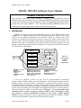
hown
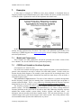
in Figure 1-1, is a high-performance interactive and complete software facility used for a wide
range of systems synthesis, optimization, and validation. While the software suite can be
executed as a stand-alone tool, interface provisions are made for common external data sets on
input (e.g., Data Acquisition standards, MATLAB) and plotting/reporting tools on output. The
capability also exists for individual users to integrate to their custom or proprietary data sets
through a published intermediate format and template. This supports ASCII, telemetry-encoded,
or even binary level data samples.
Frequency Response Identification
(FRESPID)
Frequency Response Fitting
(NAVFIT)
Multi-Input Conditioning
(MISOSA)
Frequency Response
Window Combination
(COMPOSITE)
Time History Data
Plot and Report Utilities
Derivative Identification
(DERIVID)
State Space Verification
(VERIFY)
Figure1-1:
The Top-Level
CIFER®
Product
Organization
Model Matrices
Comprehensive Identification from FrEquency Responses (CIFER)
•
•
•
FRESPID - Frequency Response
Identification
MISOSA - Multi-Input
Conditioning
COMPOSITE - Multi-Window
Averaging
•
•
•
DERIVID- Generalized Stability Derivative
Identification (from frequency responses)
VERIFY-State Space Model Verification
NAVFIT - Calculates Low-Order Transfer
Function (from hi-order transfer function or
frequency response data)
•
•
•
Screen Subsystem - User Interface
Utilities Suite - Special functions, plotting,
conditioning, etc.
DB Subsystem - Raw, Intermediate,
Processed data and indexing
I
nt
he pa
s
t
, CI
FER®’
s primary use has been for high-performance aerodynamic
systems/controls modeling, analysis, test, and optimization. It has also been uniquely proven for
handling qualities and related analyses; particularly for frequency-domain intensive ADS-33
referenced specification and testing. Vibration analysis; flutter analysis; wind tunnel and flight
test characterizations; and simulator development, validation, and optimization are just a few of
its other past and continuing uses. Other high value CIFER® adaptations are not based on how it
has been used, though. Rather it is based on what CIFER® does. For any measurable system
excitation/response set (time or frequency domain), CIFER® assesses the frequency content
a
nd pr
oduc
e
s an ac
c
ur
a
t
e ma
t
he
mat
i
c
a
ld
e
s
c
r
i
p
t
i
on oft
hats
y
s
t
e
m’
sc
o
mpl
e
xd
y
na
mi
c
behaviors. With its strong basis in proven signal processing and analysis techniques, CIFER®
uses extend well beyond the flight/vehicle development and test regime.
CasalCorp ©September 2005
Page 1
CI
FER®Sof
t
wa
r
eUs
e
r
’
sMa
n
u
a
l
Figure 1-2 depicts the overall CIFER® process. This is an empirically based technique,
operating on measured excitation data (continuous or pulse) and system responses. For our
purposes the system/subsystem/component can be of any size or domain, so long as it can be
instrumented to collect the needed signal data.
Frequency
Inputs
(Stimulus/Events)
Raw Response
Collection
Data Compatibility
& State Estimation
Multi-variable
Spectral Analysis
Conditioned
Frequency-Responses
&
Partial Coherences
Transfer-Function
Modeling
The CIFER®
Frequency-domain
system identification
process
Identification
Algorithm
Freq.-Response
Identification
Criterion
+
-
Mathematical Model
Dynamic Behavior Derivatives
and Time Delays
Initial
Values
Dissimilar Reference
Data not used in
Identification
Verification
Sensitivity Analysis
&
Model Structure
Determination
ANALYSIS APPLICATION (interactive, semi-automated, automated)
Figure 1-2:“CI
FER® i
sbas
e
dnotonl
yons
ounds
c
i
e
nc
e
,butons
ounde
ngi
ne
e
r
i
ng”
Other important aspects of our use of CIFER®’
spr
oc
e
s
s
i
ngf
eatures in our approach include:
Tools and results exercised and proven over 14 years of use; recognized as world bestin-class for applications addressing real-world problems in real-world conditions
Significant relevant data and experience can be supplemented with minimal additional effort
and cost to any future program(s)
Non-real-time and real-time analysis directly supported
Directly relevant identification algorithms are highly exercised and tuned
Flexible and interactive definition of identification model structures
Non-Parametric Modeling directly supported –no a priori assumptions are needed
a
boutt
he“s
y
s
t
e
m”or
de
r
,
s
t
r
uc
t
ur
e
,orc
ompos
i
t
i
on
Fully automated weighting function selection based on frequency-response accuracy
Built-in and reliable parameter accuracy metrics provides added confidence in results over
spectral region of interest and importance
Integrated procedure for identification and model structure determination
Time-domain verification of models, including identification of offsets and biases
1.1 ‘
CaseMet
hodol
ogy’
As discussed in t
h
i
sUs
e
r
’
sMa
nua
l
,t
het
e
r
m‘
c
a
s
e
’r
e
f
e
r
st
oa
l
lo
ft
heu
s
e
ri
n
put
sr
e
qu
i
r
e
df
o
r
a single execution of any program (FRESPID, MISOSA, and so on). A complete set of inputs is
saved and can later be retrieved via a user-defined case name. This mechanism is implemented
for all the major computational programs in the CIFER® software system, except NAVFIT.
CasalCorp ©September 2005
Page 2
CI
FER®Sof
t
wa
r
eUs
e
r
’
sMa
n
u
a
l
Case information is contained in various commons and is read from or written as records on
the database. The parameters for DERIVID and VERIFY were divided into several subcategories; e.g. MODel parameters, SENsor coefficients, F-matrix values, etc. Each subcategory
is stored in a separate file used by both DERIVID and VERIFY. Specialized utility programs also
use these data records as needed.
Case names may be up to 8 characters, although DERIVID allows 12 characters. Since
case names are used as the prefix of various file names, DO NOT use names with any character
which will cause a file naming error when an extension is added. Also, DO NOT use underscores
in case names since underscores are added by the software to create frequency response names.
When all variables are set to the user's satisfaction, the program submits a job to the batch
queue to do the computations. The name of the batch job is the case name preceded by a 3character code specifying the parent program. For example, a FRESPID job computing
frequency responses for the XVLATSWP case will be called FRE XVLATSWP. The user will
be notified when the job completes, and a log file will be created. Files of the form
progr_case.COM.next# and progr_case.OUT.next# will be produced and saved in the batch
directory identified by the active SIFDEF file (see Section 5).
For example,
FRE_XVLATSWP.COM.01 and FRE_XVLATSWP.OUT.01.
1.2 Time History Data (THD) Files and CIFER® Databases
It is essential to recognize the distinction between THD files upon which CIFER® operates
and frequency response databases produced by those operations. The frameworks for each are
produced with installation. Pointers to the databases (*.dat and*.idx) and to type-dependent time
history files (such as *ct or *.mat) for a given analysis or session are formed via the SIFDEF
construction discussed later in this manual (sections 1.3 and 5).
The usual first step in using CIFER® is the analysis of time history data with the FRESPID
utility. CIFER® implements four built-in mechanisms for accessing time history data files. The
user selects between these methods via his response to the “Time history source:”
query on FRESPID screen three. These time histories can come from a variety of sources and
schemes, but the most common are:
CIFER Binary - individual files containing one channel of data, associated with one
parameter
CIFERTEXT or CTDIF –comma or space-delimited text file with header and a
matrix of parameters and their data
Site-specific data formats and exchange mechanisms (linked via READMIS)
A third-party application (EXCEL and MATLAB directly supported)
We discuss each of these next. There remain several NASA-specific time history schemes,
including TRENDS and FLYTE, but these are no longer widely used so are not discussed further.
Please note that CIFER® does NOT rewrite time histories back to the originating source.
A time history is uniquely identified by the aircraft, flight, event, and channel name. Start
and stop time within the time history record may also be specified. Depending on the format this
may be in the file itself, or via a CIFER® Program screen. Given these items and a code
indicating which database scheme to use, the time history interfaces can go read the correct
file(s)/records(s) and return an array of data.
CasalCorp ©September 2005
Page 3
CI
FER®Sof
t
wa
r
eUs
e
r
’
sMa
n
u
a
l
1.2.1
CIFER Binary (Type 1)
File — Th
i
sc
or
r
e
s
pond
st
oas
i
mp
l
e“
b
i
na
r
y
”da
t
af
i
l
ef
or
ma
to
ft
het
y
peus
e
di
nt
h
e
sample time history files distributed with the CIFER® package. These files consist of a single
vector of floating point data, structured in such a way that they can be read by the following
simple FORTRAN code segment1:
DO i=1, npts
READ( lun ) data(i)
END DO
Because Type 1 time history files contain only the data points themselves, the user must enter
the time step between samples2 (in seconds) in the corresponding field of FRESPID screen three.
Finally, CIFER® requires that Type 1 time history files must be stored in a specialized directory
t
r
e
es
t
r
uc
t
ur
e
,ba
s
e
dupon“
f
l
i
g
htnumbe
r
”a
nd“
e
v
e
nt
”
.Thi
st
r
e
ei
sr
oo
t
e
da
tt
h
el
oc
a
t
i
onpo
i
nt
e
d
to by the CIFER® environment variable THLOC. Figure 1-3 illustrates a typical directory tree
containing Type 1 files.
Note the manner in which the flight and event numbers are encoded into the subdirectory
names and file names. In addition to the flight and event number parameters, the file name itself
encodes a third parameter, the data channel name, as follows:
<channel>E<event no>.<flight no>
THLOC
Figure 1-3:
Typical Type 1 Time
History Directory Tree
F = Flight Number
Faaa
Fbbb
Errr
Esss
Fccc
Exxx
E = Event Number
mmmmErrr.bbb
nnnnErrr.bbb
ppppErrr.bbb
The CIFER® software system comes with a variety of utilities to assist the user in this file
organization. One of those is mvhistories, which aids in creating this tree of CIFER® time
histories. If all files are correctly named and reside in a single directory, then invoking this utility
will create subdirectories and move the files into their proper places.
1
Note that, as far as the record structure of the data file is concerned, this is most definitely not
e
qu
i
v
a
l
e
n
tt
ot
h
e“
i
mpl
i
e
dl
oop”f
or
m READ(lun) (data(i), i=1, npts).
2
CIFER always assumes that data are equally spaced in time.
CasalCorp ©September 2005
Page 4
CI
FER®Sof
t
wa
r
eUs
e
r
’
sMa
n
u
a
l
1.2.2
CIFERTEXT (Type 5) or CTDIF (Type 8)
CIFER® WINTEL now supports a more compact and exchangeable ASCII input format that
combines all channels needed for an analysis. These formats are similar, with the only effective
difference being the header information.
CIFERTEXT Format
CIFERTEXT files follow this simple effective format:
Record 1 :
Record 2 :
Record 3 :
A floating point number representing the sampling period (delta time)
A list of channel names separated by spaces and/or tabs
Floating point values, separated by spaces and/or tabs. Each line should
contain as many values as there were channel names defined in Record 2.
Figure 1-4 shows a sample of a CIFERTEXT file.
Figure 1-4: CIFERTEXT file sample
CTDIF Format
CTDIF varies from the CIFERTEXT format only in the details of the header:
Record 1 :
Record 2 :
Record 3 :
Record 4 :
Record 5 :
User defined (e.g., flight/event references)
User defined (e.g., analysis-specific keywords)
User defined (e.g., a text description of the file)
A list of channel names separated by spaces and/or tabs
Floating point values, separated by spaces and/or tabs. Each line should
contain as many values as there were channel names defined in Record 4.
I
nCTDI
F,“
t
i
me
”i
sof
t
e
no
neoft
hec
ha
nn
e
l
s(
f
i
r
s
tc
ol
umnsuggested) for the DT reference.
Figure 1-5: CTDIF file sample
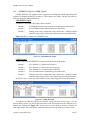
To complete the THD files link for your analysis session, when you select Types 5 or 8 for
the time history source, you will be presented with screen 3B (not shown in the CIFER® Us
e
r
’
s
Manual, but illustrated as Figure 1-6). On this screen you are asked to provide a filename for
each flight number and event number combination that you have specified on previous screens.
CasalCorp ©September 2005
Page 5
CI
FER®Sof
t
wa
r
eUs
e
r
’
sMa
n
u
a
l
1.2.3
READMIS (Type 4)
The formats of this type time history files are completely user defined. In order to access
these files, CIFER® will call a user-supplied routine named READMIS (an acronym for READ
MIScellaneous data formats). In the WINTEL version of CIFER®, the READMIS routine must
be structured as a Dynamic Link Library (DLL). This library may be compiled independently of
the CIFER® code, and need only be placed in the CIFER® “
b
i
n”di
r
e
c
t
or
yi
no
r
de
rt
obe
c
ome
available to CIFER® at runtime.
Because a user who works with several types of time history files could easily forget exactly
which READMIS DLL was currently in use, the READMIS library must also implement a
“
READMI
S_I
DENT”f
unc
t
i
onwhi
c
h,whe
nque
r
i
e
dbyCI
FER®, will provide a user-defined
identification string. This string will be displayed on CIFER® s
c
r
e
e
nt
h
r
e
ene
x
tt
oop
t
i
on“
4”
,i
n
p
l
a
c
eoft
hewo
r
d“
READMI
S”
.
Beyond these requirements, CIFER® places no restrictions on the structure of the READMIS
library or the manner in which the time history data itself is accessed or stored. In particular,
there is no requirement that the data be stored in files which are named and arranged in a
directory hierarchy such as was one shown in Figure 1-3.
The call arguments for the READMIS routine are well documented in the header block for
t
he‘
READMI
Ss
t
ub
’(
as
a
mpl
eREADMI
Sc
odepr
ov
i
de
d wi
t
ht
h
i
sp
a
c
k
a
g
e
,s
e
ebe
l
ow)
,
however, a few further comments about time history data organization are in order here. As
noted in the case of Type 1 time history data files described above, CIFER® regards time history
d
a
t
aa
sor
g
a
n
i
z
e
da
r
oundt
hepa
r
a
me
t
e
r
s‘
f
l
i
g
htnumbe
r
’
,‘
e
v
e
ntn
umbe
r
’a
nd‘
c
ha
nne
lna
me
’
.
And indeed, the READMIS arguments flightNo, eventNo, and channel convey exactly this
information into the READMIS module.
Once again, when you select option 4 for the time history source, you will be presented with
screen 3B (not shown in the CIFER® Us
e
r
’
sMa
nua
l
,b
uti
l
l
u
s
t
r
a
t
e
dhe
r
e
;s
e
eFigure 1-6). On
this screen you are asked to provide a filename for each flight number and event number
combination that you have specified on previous screens. This filename information will be
made available to READMIS via the filename argument.
Of course, your READMIS data may not reside in individual files at all — it may be located
in a database or grouped in some other fashion in container objects. Thus, it is important to
realize that, for Type 4 time history data, CIFER® makes no use of these various pieces of
information, other than to pass them to your READMIS routine. You may encode any type of
information into these parameters that will help you locate your data. For example, it may be
more appropriate for your purposes to associate a directory path wi
t
he
a
c
h“
f
l
i
g
htnumbe
r
”a
nd
“
e
v
e
ntnumbe
r
”pa
i
r
,r
a
t
h
e
rt
h
a
naf
i
l
ena
me
.(
Or
,y
ouma
yc
hoos
et
oe
nt
e
rnot
h
i
n
ga
ta
l
l— it is
n
otne
c
e
s
s
a
r
yt
oe
nt
e
r“
f
i
l
ena
me
s
”i
fy
ouha
v
enon
e
e
dfor an additional qualifier.)
Case: XVLATSWP
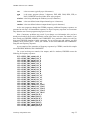
FRESPID:3B
Comments: Lateral frequency sweep for XV-15 in hover
Evnt/Flt
File Name
--------
-----------------------------------------------
883 150
mydata.fu
884 150
mydata.bar
0
0
0
0
0
0
0
0
0
0
0
0
0
0
0
0
Figure 1-6: FRESPID Screen 3B
CasalCorp ©September 2005
Page 6
CI
FER®Sof
t
wa
r
eUs
e
r
’
sMa
n
u
a
l
The READMIS DLL Projects
In order to generate a READMIS DLL for use with the CIFER® package, the user will need
to have access to an integrated development environment (IDE) capable of building standard
Win32 DLL modules. Although any IDE with this capability may be used, the CIFER® package
is distributed with sample projects for two common WINTEL I
DE’
s
:Vi
s
u
a
lC/
C++a
ndDi
g
i
t
a
l
Equi
pme
ntCo
r
por
a
t
i
on’
sVi
s
ua
lFo
r
t
r
a
n90.I
fy
ouha
v
ee
i
t
he
ro
ft
he
s
eI
DE’
s
,y
oune
e
don
l
y
open the appropriate project, insert code specific to your data access requirements into the
READMI
St
e
mpl
a
t
eor“
s
t
ub”
,a
nds
e
l
e
c
t‘
Re
b
u
i
l
dAl
l
’f
r
om t
he‘
Bu
i
l
d
’me
nu.I
fy
o
uwi
s
ht
o
use an IDE other than one of these, you may still be able to use the template modules as a starting
point for your development efforts.
In addition to the template modules, each project contains an actual working sample
READMIS program, which may be substituted for the READMIS stub code when building the
project. This fully functional READMIS program will generate a DLL that duplicates the
operation of the Type 1 option. That is, it will read Type 1 time history files from the directory
tree rooted at THLOC in exactly the same manner as would be the case if option one were
s
e
l
e
c
t
e
di
nr
e
s
pon
s
et
ot
h
e“
Ti
mehi
s
t
o
r
ys
our
c
e
?
”que
r
yons
c
r
e
e
nt
hr
e
e
.
All of these modules, both the templates and the code for the Type 1 READMIS samples, are
meticulously documented. Each is a self-contained tutorial covering everything you will need to
know in order to implement your own READMIS code. However, as you approach the task of
constructing your READMIS module, please realize that it is precisely because of the depth of
this documentation that these programs may seem somewhat formidable; appearances
notwithstanding though, there is actually very little coding required to produce a usable routine.
Organization of the Project Directories
The READMIS projects are located in the directory $cifroot/source/readmis, in the
folders readmis_f90 and readmis_c. The directory structure of each is identical; the
structure of the readmis_c directory tree for the MATLAB Binary READMIS library is shown
in Figure 1-7 3.
Figure 1-7: READMIS Directory Tree
In the case of the C-language project, the files readmis.c.STUB and
readmis.c.TYP1, located in the $cifroot/readmis/readmis_c directory, contain
respectively the code for the template READMIS routine and the sample Type 1 emulation
READMIS routine.
3
Some files may appear with different icons on other machines.
CasalCorp ©September 2005
Page 7
CI
FER®Sof
t
wa
r
eUs
e
r
’
sMa
n
u
a
l
To build either of these modules using the predefined project, simply copy the desired file
into the $cifroot/readmis/readmis_c /libreadmis directory and rename it to
readmis.c. (The procedure is analogous for the Fortran project. The corresponding files are
readmis.for.STUB and readmis.for.TYP1.)
The IDE may be launched by double-clicking on the file libreadmis.dsw, located in the
$cifroot/readmis/readmis_c/libreadmis di
r
e
c
t
or
y
. Se
l
e
c
t
i
ng‘
Re
bu
i
l
da
l
l
’f
r
om
t
he‘
Bui
l
d’me
nuwi
l
lc
ompi
l
e
,l
i
nka
ndi
ns
t
a
l
lt
her
e
s
ul
t
i
ngDLLi
n
t
ot
heCIFER bin directory.
(Should it become necessary to perform the installation manually, the DLL may be found in the
$cifroot/readmis/readmis_c/libreadmis/ Release directory, once the build
operation has been successfully completed.)
Implementing a READMIS Routine
As noted above, the sample and template READMIS files are completely documented and
should provide all the information that you will need to implement a site-specific version. This
section provides only a brief overview of the issues which must be addressed during that process;
they are as follows:
You will be required to provide a 14-char
a
c
t
e
r“
i
d
e
nts
t
r
i
ng
”whi
c
hwi
l
lbeus
e
dt
oi
de
n
t
i
f
y
the READMIS DLL on FRESPID screen three. This string may contain any information you
wish. Its purpose is to serve as a mnemonic aid to help you determine, at runtime, which DLL
you are using.
TheREADMI
Sr
out
i
newi
l
lbec
a
l
l
e
di
nt
wodi
f
f
e
r
e
nt“
mode
s
”a
sCI
FER e
xe
c
ut
e
s
. The
mode is indicated by the value of the mode argument to the READMIS call. If mode=1,
CIFER expects READMIS to return, in the DELTAT argument, the time step between data
elements. (It is important that no actual time history data be returned when mode=1.)
When
READMIS is entered with mode=2, CIFER will expect it to return the actual time
history data in the ARRAY argument. The number of data points provided must be returned
in the NPTS argument, and this number must be less than or equal to the maximum array size
as given by the arraysiz argument. (This dimension is nominally 100,000 points, although
implementation may vary from platform to platform.)
The areas of the template file which must be modified to meet these requirements are clearly
marked. To see an actual example of a functioning READMIS routine, examine the
readmis.TYP1 file for the language of your choice.
1.2.4
Third Party Software Interfaces
CIFER® may be connected to data generated from 3rd party software such as EXCEL,
MATLAB, LabView, OriginLab, and the like. This is best done by exporting the data sets from
the external application into one of the ASCII formats just described (CIFERTEXT or CTDIF).
Most modern analysis and simulation software is capable of this directly or using simple utilities.
Alternatively, a READMIS DLL may be constructed specific to the as-formatted data (discussed
next). Finally, if the data is already in binary channels as described in section 1.2.1 then these can
be organized into the needed directory structure, and linked by pointing to the directory through
Setup Utilities.
Installing the MATLAB DLL
Recognizing the widespread use of MATLAB in the engineering and science enterprises that
CIFER® supports, a pre-constructed MATLAB READMIS DLL is delivered with the standard
installation. Only one READMIS DLL may be attached at a time.
CasalCorp ©September 2005
Page 8
CI
FER®Sof
t
wa
r
eUs
e
r
’
sMa
n
u
a
l
Please note that standard MATLAB (not binary) data may be exchanged via simple
e
xt
r
a
c
t
i
on
si
nt
oCI
FER®’
sASCII formats: CIFERTEXT or CTDIF.
The purpose of this DLL is to provide the means to read MATLAB Binary data.
The
MATLAB binary file must contain a "time" (lower case) array and arrays of the same size as
"time" for all channels to be read. The DT (delta-time) is the average of the time steps, but each
time step should be as near DT as possible. Differences of up to two percent from DT are
allowed. This MATLAB binary file can be created via the MATLAB command:
save file.mat time chan1 chan2 chan3 ... chann
where "..." is not the MATLAB continuation indicator but signifies channels 4 through n1 by whatever name.
These files are portable between platforms.
The following instructions replace the default READMIS DLL with the MATLAB DLL.
The basic requirements to begin are:
The MATLAB DLL: libreadmis.dll.matlab
MATLAB libraries need to be known at run time if the MATLAB binary reader
READMIS DLL is the active READMIS library.
If MATLAB libraries are not available, the MATLAB binary reader READMIS DLL
MUST not be the active READMIS library.
First, save the current DLL:
Using the MKS Unix shell (accessible directly or by launching CIFER, then exiting –
leaving the Unix window open and active)
cd $cifbin
mv libreadmis.dll libreadmis.dll.fstub
Please Note: If another libreadmis is already installed, then save it to an appropriate
name instead of libreadmis.dll.fstub, e.g., libreadmis.dll.ctdif. Remember that the ID is
displayed on screen FRESPID:3.
Next, obtain the new MATLAB binary reader READMIS DLL, and install (again using the
MKS Unix shell)
cd $cifbin
mv <where you put the file>/libreadmis.dll.matlab libreadmis.dll
If you deposited the file directly into $cifbin:
mv libreadmis.dll.matlab libreadmis.dll
Add MATLAB DLLs to the runtime environment (again using the MKS Unix shell):
export PATH="${PATH};<your MATLAB directory>\bin"
Example:
export PATH="${PATH};C:\MATLABR11\bin"
Note: It may be desirable to change the PATH environment variable as shown in the
Installation Guide and Release Notes so the MATLAB DLLs are available every time a CIFER
shell is started.
CasalCorp ©September 2005
Page 9
CI
FER®Sof
t
wa
r
eUs
e
r
’
sMa
n
u
a
l
1.2.5
Byte Swapping (Big-Endian-Little-Endian Conversions)
Some CIFER® users must migrate their databases and analyses between Unix and WINTEL
platforms. To facilitate such exchanges, the needed databases now are portable among Unix and
WINTEL CIFER® version 4.1.00 and above. Before these versions, the generally big-endian
architecture of most Unix systems and the little-endian architecture of PCs running either
Windows or Linux meant that data created on one could not be read by CIFER® on the other.
Byte-swapping software has been added to overcome this problem. No matter where or when
the database was created or last modified, it is portable between platforms as long as the installed
version of CIFER® used to read the database meets the version 4.1.00 requirements.
Swapping is done transparently when records are read from the database; records are always
written without swapping. As a database is copied between the two types of machine, and
records are updated, it is likely and acceptable that records of both *-endian will exist.
Remember that a database comprises a data file (*.dat) and an index file (*.idx). If ftp is used
to transfer a database, use binary mode. This should go without saying for the binary data file,
but it is also important to use this mode for the index file. Otherwise, when an index file is
copied to a Windows machine in ASCII mode, a DOS end-of-record character is added to every
line, breaking the database software.
1.3 Frequency Response Database & Naming Conventions
The core of the CIFER® analysis technique is the generation, conditioning, fitting, and
combining of frequency responses from control and output time histories. Frequency responses,
such as those produced by FRESPID, are generated either as stand-alone ASCII files or are
written to the CIFER® frequency response database. The latter provides a more compact storage
method and stores information about how the frequency response was generated. However,
because of the file format, the data is not directly human-readable and can be accessed only via
the CIFER® software. (Note that the 'print frequency response utility' allows generation of an
ASCII file containing frequency response values from the database.) The format of these files is:
Record 1:
Descriptive information about the frequency response
Record 2-n:
Frequency, magnitude, phase, coherence, gxx, gyy, gxy, real part of
response, imaginary part, error (one record per frequency value)
Related CIFER® matrix sizes are defined as follows:
[M] = ns x ns
where, ns = number of states (max of 40)
[F] = ns x ns
no = number of outputs (max of 20)
[G] = ns x nc
nc = number of controls (max of 10)
[Tau] = no x nc
[H] = no x ns
[Xi] = no x nc
A frequency response, then, consists of a set of arrays and descriptive information The arrays
contain the frequency values, frequency response magnitude, phase, coherence etc. The attributes
summarize how and when the response was created. In order to keep track of frequency
responses the following naming system is used.:
case_pgm_windows_inchan_outchan
where,
CasalCorp ©September 2005
Page 10
CI
FER®Sof
t
wa
r
eUs
e
r
’
sMa
n
u
a
l
case
is the case name (typically up to 8 characters)
pgm
is the source program (always 3 characters: FRE, MIS, COM, DER, VER, or
NAV); DERIVID can also produce DTA as the program.
windows is the string indicating the window(s) used (5 characters)
inchan
is the user-defined control/input channel (up to 4 characters)
outchan is the user-defined observer/output channel (up to 4 characters)
As the user progresses through the CIFER® programs, additional frequency responses are
generated at each step. All intermediate responses are kept. Frequency responses are overwritten
only when the user reruns a program using a previous case.
Note: Consistency problems may result if you change case information after you have
already used results from an earlier (different) version of the same case name. For instance, if you
have already run FRESPID, MISOSA, and COMPOSITE for a particular window size and you
then rerun FRESPID changing window parameters for an existing case and window, you will
probably cause yourself grief .... unless you continue on and rerun MISOSA and COMPOSITE
using the new frequency responses.
As an example of the generation of frequency responses by CIFER®, consider this sample
run of FRESPID, MISOSA, and COMPOSITE.
For a case involving two controls, four outputs, and five windows, FRESPID creates the
following 40 frequency responses:
XVLATSWP_FRE_A0000_AIL_P
XVLATSWP_FRE_0B000_AIL_P
XVLATSWP_FRE_00C00_AIL_P
XVLATSWP_FRE_000D0_AIL_P
XVLATSWP_FRE_0000E_AIL_P
XVLATSWP_FRE_A0000_AII._R
XVLATSWP_FRE_0B000_AII._R
XVLATSWP_FRE_00C00_AIL_R
XVLATSWP_FRE_000D0_AIL_R
XVLATSWP_FRE_0000E_AIL_R
XVLATSWP_FRE_A0000_AIL_AY
XVLATSWP_FRE_0B000_AII._AY
XVLATSWP_FRE_00C00_AIL_AY
XVLATSWP_FRE_000D0_AIL_AY
XVLATSWP_FRE_0000E_AIL_AY
XVLATSWP_FRE_A0000_AII._VDOT
XVLATSWP_FRE_0B000_AIL_VDOT
XVLATSWP_FRE_00C00_AIL_VDOT
XVLATSWP_FRE_000D0_AIL_VDOT
XVLATSWP_FRE_0000E_AIL_VDOT
XVLATSWP_FRE_A0000_RUD_P
XVLATSWP_FRE_0B000_RUD_P
XVLATSWP_FRE_00C00_RUD_P
XVLATSWP_FRE_000D0_RUD_P
XVLATSWP_FRE_0000E_RUD_P
XVLATSWP_FRE_A0000_RUD_R
XVLATSWP_FRE_0B000_RUD_R
CasalCorp ©September 2005
Page 11
CI
FER®Sof
t
wa
r
eUs
e
r
’
sMa
n
u
a
l
XVLATSWP_FRE_00C00_RUD_R
XVLATSWP_FRE_000D0_RUD_R
XVLATSWP_FRE_0000E_RUD_R
XVLATSWP_FRE_A0000_RUD_AY
XVLATSWP_FRE_0B000_RUD_AY
XVLATSWP_FRE_00C00_RUD_AY
XVLATSWP_FRE_000D0_RUD_AY
XVLATSWP_FRE_0000E_RUD_AY
XVLATSWP_FRE_A0000_RUD_VDOT
XVLATSWP_FRE_0B000_RUD_VDOT
XVLATSWP_FRE_00C00_RUD_VDOT
XVLATSWP_FRE_000D0_RUD_VDOT
XVLATSWP_FRE_0000E_RUD_VDOT
In addition, if cross-correlation of inputs is requested, then the following responses are also
computed (you must generate these if you are going to run MISOSA):
XVLATSWP_FRE_A0000_AIL_RUD
XVLATSWP_FRE_0B000_AIL_RUD
XVLATSWP_FRE_00C00_AIL_RUD
XVLATSWP_FRE_000D0_AIL_RUD
XVLATSWP_FRE_0000E_AIL_RUD
Running MISOSA to condition the AIL responses for RUD (20 responses, one for each
output and window) generates:
XVLATSWP_MIS_A0000_AIL_P
XVLATSWP_MIS_0B000_AIL_P
(uses AIL_P, AIL_RUD)
etc.
XVLATSWP_MIS_A0000_AIL_R etc.
XVLATSWP_MIS_A0000_AIL_AY etc.
XVLATSWP_MIS_A0000_AIL_VDOT etc.
If you want to condition the responses for other inputs, you must rerun MISOSA with a
different primary input. COMPOSITE will then combine frequency responses for the five
windows:
XVLATSWP_COM_ABCDE_AIL_P
XVLATSWP_COM_ABCDE_AIL_R
XVLATSWP_COM_ABCDE_AIL_AY
XVLATSWP_COM_ABCDE_AIL_VDOT
CasalCorp ©September 2005
Page 12
CI
FER®Sof
t
wa
r
eUs
e
r
’
sMa
n
u
a
l
2. System Requirements
2.1 Operating System
This version of CIFER® and its supporting components should run on any NT4, W2K, or XP
WINTEL workstation or server system. CIFER® is also available with equivalent functionality
for Unix Operating Systems (Solaris, IRIX), Linux, and MAC OS9 (requires 3rd party software).
No attempt has been made to test CIFER® on Windows 95, 98, or ME and no representation
is made as to CIFER®’
ss
u
i
t
a
b
i
l
i
t
yf
orus
eons
uc
hs
y
s
t
e
ms
.
2.2 Program Versions
You may see some differences between actual program/utility screens shown in this manual
and the actual displays. Some of the Program User descriptions provided in this manual are for
earlier versions of the CIFER® software version. The purpose and functionality of each
program/utility screen is generally unchanged.
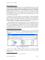
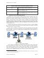
2.3 Single and Multiple User CIFER® Systems
A single user CIFER® installation is one in which only one person of the (perhaps) many
people with accounts on the system, actually uses CIFER®. On such a system, it is
recommended but unnecessary to create separate user configurations and directory structures in
order to segregate the operational environments of multiple users. If the standard setup is
retained you will create databases and customized data input routines directly within the primary
CIFER® directory tree without fear of impacting others. However, you must then ensure that this
data is saved and restored properly when applying any future CIFER® version updates.
However, on systems which support multiple CIFER® users, it is
necessary to duplicate, on a per user basis, certain portions of the primary
CIFER® directory structure in order to provide segregated areas for the
storage of user data. In these installations, the cifroot environment
variable will point to the primary CIFER® directory (as created during
installation), while the cifhome environment variable will point to the
r
ootofe
a
c
hi
ndi
v
i
du
a
lu
s
e
r
’
sCI
FER® di
r
e
c
t
or
yt
r
e
e
.The
s
e“
p
e
rus
e
r
”
directory trees are not subtrees of the primary CIFER® directory, but
rather, are usually l
oc
a
t
e
di
nt
heus
e
r
’
sowndi
r
e
c
t
or
y
.(
Foramor
e
complete explanation, including specific instructions on creating these
user directories, see the CIFER® Installation Guide and Release Notes –
Version 4.1.00 or later.)
Figure 2-1
Environment Tab of the (WINTEL) System Applet
CasalCorp ©September 2005
Page 13
CI
FER®Sof
t
wa
r
eUs
e
r
’
sMa
n
u
a
l
3. Summary of CIFER® Programs
CIFER® for the WINTEL platform is distributed as a set of (executable) Programs, scripts,
and data. As already introduced the main Programs consist of FRESPID, MISOSA,
COMPOSITE, DERIVID, NAVFIT, VERIFY, and a range of specialized utilities (administrative,
analytical). This section provides a brief overview of each. Each of these programs and utilities
is completely described later in this document.
FRESPID
Frequency Response
IDentification
MISOSA
Multi-Input Conditioning
COMPOSITE
Multi-window Averaging
DERIVID
Generalized Stability
Derivative Identification
from Frequency Responses
Page 1 –Select Case and Aircraft (session indexes)
Page 2 –Enter Controls (up to 10 inputs) and Observers (up to 20 outputs)
Page 3 –Enter flights and events to be analysed (start/stop times optional)
Page 4 –Define composite control (input) channels and units
Page 5 –Define composite observers (output) channels and units
Page 6 –Set desired combinations of input/output to compute (incl. ALL)
Page 7 –Condition input time histories
Page 8 –Set up window parameters (manual or automatic)
Page 9 –Set plotting options
Page 10 –Launch frequency responses calculations
Page 1 –Select Case and Aircraft (session indexes)
Page 2 –Check/Change session setup, incl. controls, outputs, and windows
Page 3 –Set desired combinations of input/output to compute (incl. ALL)
Page 4 –Set up plots
Page 1 –Select Case and Aircraft (session indexes)
Page 2 –Check/Change session setup, incl. controls, outputs, and windows
Page 3 –Set desired combinations of input/output to compute (incl. ALL)
Page 4 –Set up plots
Page 1 –Select Case and Aircraft (session indexes)
Page 2 –Set up links to matrix names [ M, F, G, Tau, H(s) ]
Page 3 –Present model parameters: state names, observers, controls
Page 4 –Set desired combinations of input/output to compute (incl. ALL)
Page 5 –Edit sensor coefficients (alternate method)
Page 6 –Name the responses used in the identification (semi-automatic)
Page 7 –Name the responses used in the identification (manual)
Page 8 –Specify the terms of the M Matrix
Page 9 –Specify the terms of the F Matrix
Page 10 –Specify the terms of the G Matrix
Page 11 –Specify the terms of the T Matrix
Page 12 –Establish named derivatives in M Matrix
Page 13 –Establish named derivatives in F Matrix
Page 14 –Establish named derivatives in G Matrix
Page 15 –Establish named derivatives in T Matrix
Page 16 –Fix the H matrix, and launch analysis
Others
CasalCorp ©September 2005
Page 14
CI
FER®Sof
t
wa
r
eUs
e
r
’
sMa
n
u
a
l
Page 1 –Select Case and Aircraft; choose DERIVID or VERIFY
Page 2 –Set up links to matrix names [ M, F, G, Tau, H(s) ]
Page 3 –Present model parameters (subset of DERIVID model parameters)
Page 4 –Display sensor coefficients for all observer/control combinations
Page 5 –Display M Matrix elements
Page 6 –Display F Matrix elements
Page 7 –Display G Matrix elements
Page 8 –Display H(s) Matrices (output structure for VERIFY)
Page 9 –Display H Matrix elements
Page 10 –Display j Matrix elements
Page 11 –Display T Matrix elements
Page 12 –Set up source of control channels (time history data)
Page 13 –Set up source of observer channels (time history data)
Page 14 –Modi
f
yc
on
t
r
olc
h
a
n
n
e
lf
or“
t
h
i
s
”mode
lr
e
c
or
d
Page 15 –Est
i
ma
t
ebi
a
sf
or“
t
h
i
s
”e
l
e
me
n
toft
h
es
t
a
t
ee
qu
a
t
i
on
Page 16 –Mode
lo
bs
e
r
v
e
rc
h
a
n
n
e
lf
or“
t
h
i
s
”mode
lr
e
c
or
d
Page 17 –Select part or all of the time history sample
Page 18 –Condition time histories
VERIFY
State Space Model
Verification
Interactive calculation of low order transfer function calculation from high
order transfer function or frequency response data.
NAVFIT
response
7 –RMS Utility
8 –Handling Qualities and Stability Margins
9 –Frequency Response Arithmetic
Program Parameter utilities
14 –Read ASCII Matrix File(s)
15 –Read ASCII Response into the Database
19 –QPLOT: Plot Frequency Responses
20 –Print Frequency Response Values
Database
Utilities
11 –Change CIFER Defaults
12 –Case Directory
13 –Case or Response Delete Utility
16 –Select Aircraft/Analysis (SIFDEF file)
17 –Create Aircraft (Create new db or create SIFDEF for existing db)
18 –Search Frequency Response db
27 –Database Case Copy
28 –Database Share (not available on WINTEL)
29 –Database Compress
Frequency
analysis utilities
and
Setup
Results Utilities
CasalCorp ©September 2005
31 –Plot DERIVID Results
32 –Plot VERIFY Results
33 –Tabular DERIVID Reports
34 –Tabular VERIFY Reports
35 –Print DERIVID or VERIFY Results
36 –Case Plotting Utility
37 –DERIVID or VERIFY Matrix Reports
38 –Eigenvalue Utility
39 –DERIVID Parameter Dump
Page 15
CI
FER®Sof
t
wa
r
eUs
e
r
’
sMa
n
u
a
l
4. Running CIFER@
Once you have completed the installation of the CIFER® package, made any necessary
manual adjustments to the XVision transport protocols (see Section 3 of the CIFER® Installation
Guide and Release Notes; IGRN), and rebooted your machine, you should be able to invoke
CIFER® either by double-clicking the shortcut that the installer placed on your desktop4, or by
selecting the START>Programs> Cifer>CIFER Shell menu item (Figure 4-1). Note that two
different methods for starting CIFER® may give you slightly different CIFER® windows with
different properties (e.g., a CIFER® window started via the desktop shortcut may be physically
shorter than a CIFER® window started from the Start menu).
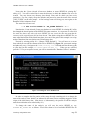
Figure 4-1: Starting the CIFER® Shell
When you launch CIFER®, you are actually starting an MKS Korn shell which then
ultimately executes the main CIFER® script, after first running several intermediate scripts to set
up CIFER®’
se
nv
i
r
o
nme
nt
.Thi
ss
t
a
r
t
u
ppr
oc
e
s
sis discussed at some length in Section 5.5 of the
IGRN, in connection with CIFER®’
s environment variables. Here, it is sufficient to note that
you will see a screen similar to the one shown in Figure 4-2 — t
h
eCI
FER “
s
pl
a
s
h”s
c
r
e
e
n
.
De
pr
e
s
s
i
ngc
a
r
r
i
a
g
er
e
t
ur
nwi
l
lt
he
nt
a
k
ey
out
oCI
FER’
sma
in menu screen (Figure 4-3), from
which you may selectively execute individual CIFER utilities5.
Figure 4-2: CIFER® Splash Screen
Figure 4-3: CIFER® Main Menu
Whe
ny
ouha
v
ef
i
ni
s
h
e
dy
ourCI
FER® s
e
s
s
i
on,y
ouwi
l
lf
i
ndy
ourc
u
r
s
ora
tt
he“
i
npu
t
p
r
ompt
”of the CIFER® main menu screen. To exit CIFER®, simply enter a carriage return and
you will be returned to the Korn shell from which CIFER® was initiated. This is a useful
4
5
If you do not wish to have the CIFER® shortcut on your desktop, it may be safely deleted.
I
ti
sn
ott
h
epu
r
pos
eoft
h
i
sdoc
ume
n
tt
o di
s
c
u
s
si
n de
t
a
i
lt
h
eope
r
a
t
i
on ofCI
FER®’
sv
a
r
i
ous
components. For an introduction to these programs please see volumes 1 and 2 of the CIFER® Class
Notes.
CasalCorp ©September 2005
Page 16
CI
FER®Sof
t
wa
r
eUs
e
r
’
sMa
n
u
a
l
environment from which to manipulate CIFER® output files, re-launch CIFER®, or perform any
other tasks for which you find a Unix-like command line interface well suited. You will find that
mos
tUni
xt
oo
l
sa
nde
di
t
o
r
sa
r
ea
v
a
i
l
a
bl
e
,a
ndt
ha
tf
e
a
t
ur
e
ss
uc
ha
s“
p
i
pe
s
”a
ndba
c
k
g
r
ound
processing work as you would expect. Furthermore, all CIFER® environment variables are
defined and available for use, making manipulations of CIFER® directories and files quite
straightforward. To restart CIFER® from within the shell, type ‘cifer’(lower case) at the
command prompt. To exit the shell entirely, type any one of ‘exit’, ‘logout’, or ‘bye’.
4.1
Customizing the CIFER® Shell Window
As they are installed, the CIFER® shortcuts present a somewhat vanilla interface in which
i
mpor
t
a
ntf
e
a
t
u
r
e
ss
uc
ha
s“
c
uta
ndpa
s
t
e
”a
n
ds
c
r
ol
l
i
nga
r
edi
s
a
bl
e
d.Youwi
l
l almost certainly
find your CIFER® user experience more productive if you take a few moments to enable some of
these features. Note, however, that the operations described in this section will require
administrative privilege, since you will be enabling these features for all users of these systemwide shortcuts.
Begin by launching an instance of the CIFER® shell from either the desktop or START menu
s
hor
t
c
u
t
s
. Ri
g
htc
l
i
c
kont
het
i
t
l
eb
a
ro
ft
heme
nua
nds
e
l
e
c
t“
Pr
ope
r
t
i
e
s
”
. Ne
xts
e
l
e
c
tt
h
e
“
Opt
i
o
n
s
”tab (Figure 4-4)
.Th
e
n,c
h
e
c
kt
heb
oxl
a
be
l
e
d“
Qu
i
c
kEdi
tMode
”
.
Figure 4-4:Enabl
i
ng“Qui
c
kEdi
tMode
”
With this mode enabled you will be able to capture screen text into the paste buffer by
depressing the left mouse button and dragging across the desired text to highlight it, and then
releasing the left mouse button to select the highlighted text. Next you can capture the selected
text by right-clicking. Captured text may be subsequently inserted at the cursor position by rightclicking a second time. This maneuver is very useful for duplicating complicated CIFER®
frequency response names!
Toe
na
bl
es
c
r
o
l
l
i
ng
,s
e
l
e
c
tt
he“
La
y
out
”t
a
boft
h
ePr
ope
r
t
i
e
spa
n
e
l(
Figure 4-5). In the
“
Sc
r
e
e
nBuf
f
e
rSi
z
e
”pa
n
e
,e
nt
e
ras
u
i
t
a
bl
yl
a
r
g
ev
a
l
ue(
e
.
g
.
,100
0l
i
ne
s
)f
ort
he“
He
i
g
ht
”
;
h
owe
v
e
r
,l
e
a
v
et
he“
Wi
d
t
h
”s
e
tt
o80c
ol
u
mns
.Ne
xt
,i
nt
h
e“
Wi
nd
owSi
z
e
”pa
n
e
,e
nt
e
ranumbe
r
of lines sufficient to give the shell window the screen coverage you would like; again, do not alter
the width of the window.
CasalCorp ©September 2005
Page 17
CI
FER®Sof
t
wa
r
eUs
e
r
’
sMa
n
u
a
l
There is one remaining customization which you may wish to consider when setting up your
CIFER® shortcuts. As it is installed, the CIFER® shell will always launch with white (actually
grayish) lettering displayed on a black background. This arrangement can be modified to any
desired combination (e.g., black lettering on a white background) by making suitable adjustments
i
nt
h
e“
Co
l
or
s
”t
a
bo
ft
h
ep
r
ope
r
t
ypa
ne
l(
Figure 4-6).
Figure 4-5: Enabling Scrolling in the CIFER® Shell
Figure 4-6: Setting CIFE®R Shell Background and
Foreground Colors
Fi
na
l
l
y
,c
l
i
c
k“
OK”t
oc
l
o
s
et
hepr
op
e
r
t
ypa
ne
l
.Wh
e
ny
oudos
o,adi
a
l
ogwi
l
la
ppe
a
ra
s
k
i
ng
if you wish to apply the changes only to the current window, or to the shortcut that launched the
window. You should select the latter in order to have the changes take effect for all subsequent
launches of CIFER® from that shortcut. (You should then launch CIFER® from the other of the
two shortcuts installed by the setup, and repeat these steps to establish the proper defaults for it as
well.)
4.2 The CIFER® Keyboard Interface
Many CIFER® utilities interact with the user via a series of data entry screens that make use
of cursor addressing. Each screen contains a number of data input fields interspersed with
descriptive text. The user can navigate from field to field within a screen using combinations of
the arrow, tab and return k
e
y
s
.Onc
et
heda
t
ac
on
t
e
ntofas
c
r
e
e
n
’
sf
i
e
l
d
si
ss
a
t
i
s
f
a
c
t
or
y, the
user can proceed to the next screen by depressing the F1 key. CIFER® does not make use of the
c
omput
e
r
’
spoi
nt
i
n
gde
v
i
c
e(
“
mous
e
”
)
.
CasalCorp ©September 2005
Page 18
CI
FER®Sof
t
wa
r
eUs
e
r
’
sMa
n
u
a
l
Table 4a summarizes the functions6 (on a typical keyboard) of the various navigational keys
used by CIFER®;
Data Entry. Once the user has navigated to a field, the procedure for data entry is
straightforward. In general, all printable characters will appear in the field as they are typed. It is
important to remember that casenames, control names, and the like [i.e. names of things] must
match exactly from use to use (including case). In addition please recognize that in this version
some CIFER® command and option selections remain case sensitive. However the authors are
removing this restriction and this should be a minimal encounter for the current user. Finally
along with the standard numeric keys, on most keyboards the numerical keypad can also be used
f
ord
a
t
ae
n
t
r
ypr
ov
i
de
dt
he“
NumLoc
k
”ha
sbe
e
ns
e
t
.
The double-wi
dt
h“
Ba
c
k
s
pa
c
e
”k
e
yl
oc
a
t
e
da
bov
et
her
e
t
u
r
n key (see Figure 6-7) is the
character rubout key; it will delete the character immediately to the left of the cursor. The small
“
De
l
e
t
e
”k
e
y
,l
oc
a
t
e
di
nt
h
es
i
x-key cluster above the arrow keys, can be used to delete the entire
contents of a field.
NOTE: A very important change was implemented for CIFER® Version NT12. Except in
the extended editing features described immediately below, the first keystroke in a field will wipe
out that field. This is the behavior of the Unix version, and some users who were familiar with it
requested that it be implemented in the Windows version also.
Extended Editing Features. One CIFER® ut
i
l
i
t
y
,t
he“
QPLOT”pr
og
r
a
m(
ut
i
l
i
t
y19)
,ha
sa
n
optional data entry protocol which is designed to provide additional editing features in order to
facilitate the entry of long frequency response names. These features are only available in screen
one of QPLOT. In this situation, all of the descriptions given in Table 4a remain valid, but the
additional capabilities described in Table 4b also apply.
Table 4a: CIFER® Keyboard Navigation and Data Entry
6
tab, right arrow
Move data entry focus right by one field. If currently in right-most field
of a screen row, then wrap to left-most field in the next screen row.
left arrow
Move data entry focus left by one field. If currently in left-most field of a
screen row, then wrap to right-most field in the previous screen row.
return, enter,
down arrow
Move data entry focus down to the most closely (vertically) aligned field
in the next row. When issued from the last line of the screen, the focus
will wrap to the top of the screen.
up arrow
Move data entry focus up to the most closely (vertically) aligned field in
the previous row. When issued from the top line of the screen, the focus
will wrap to the bottom of the screen.
any printing
character
Appears in the data field as typed (case sensitive).
backspace
Deletes the character to the left of the cursor.
del
Deletes the entire content of the current data entry field.
Users familiar with the Unix version of CIFER® will recall that keyboard mappings could be adjusted
in order to compensate for the vagaries of the many keyboard types encountered on those platforms.
This type of customization is not required on Windows platforms, since the mappings provided by
NuTCRACKER are consistent across all systems.
CasalCorp ©September 2005
Page 19
CI
FER®Sof
t
wa
r
eUs
e
r
’
sMa
n
u
a
l
F1
Accepts the data on the current screen as entered and proceeds to the next
screen.
F2
Presents a secondary navigation menu on the last line of the terminal
s
c
r
e
e
n.Th
eme
nu’
sop
t
i
o
n
sa
r
e
Continue
Backup
Main
Exit
Update
Selection of items on this menu may be made via the right or left arrow
keys, or by typing the first letter of the desired entry. Once an entry has
be
e
ns
e
l
e
c
t
e
d,de
p
r
e
s
sF1t
oa
c
c
e
pt
.“
Upda
t
e
”i
sa
ne
xc
e
pt
i
on.Ty
pe“
T”
or“
F”t
oe
na
b
l
eo
rd
i
s
a
bl
eada
t
a
b
a
s
eupda
t
e
,r
e
s
pe
c
t
i
v
e
l
y
,t
obed
on
e
after selection of an entry. It is not possible to select this item via the
a
r
r
owk
e
y
s
,nord
o
e
st
y
pi
ng“
U”ha
v
ea
nye
f
f
e
c
t
.
F3
This key is only used in specialized situations; see for example,
Class Notes Vol 2, DERIVID operations, screen 4.
F4
Presents a secondary navigation menu of the form:
Go to:
to which the user may respond with a screen number followed by
the F1 key or the RETURN key. Screen numbers entered at this
prompt may be outside of the range of actual screen numbers for
t
hepr
og
r
a
m;e
.
g
.
,“
99”wi
l
lt
a
key
out
ot
hee
ndoft
heda
t
ae
nt
r
y
segment for most of the CIFER utilities.
Table 4b: QPLOT Augmented Data Entry Features
CTRL-A
Moves cursor to the left end of the current field.
CTRL-D
Moves cursor to the right end of the current field.
CTRL-G
Moves cursor left by one character.
CTRL-L
Moves cursor right by one character.
CTRL-O
Enters character insert mode. Any printable character typed will be
inserted directly above the cursor.
<ESC>
Exits character insert mode.
any printing
character
In normal mode, overwrites the character directly above the cursor. In
character insert mode, the character is inserted directly above the cursor,
moving the right portion of the line one character to the right.
backspace
Deletes the character immediately to the left of the cursor, and drags the
right portion of the line one character to the left.
del
Deletes the entire line, even if the cursor is positioned in the interior of
the line.
CasalCorp ©September 2005
Page 20
CI
FER®Sof
t
wa
r
eUs
e
r
’
sMa
n
u
a
l
5.
Getting Started - Setting Up Databases and SIFDEF files
This section will provide an overview of CIFER® databases and the procedures for creating
them. SIFDEF files will be described, and the relationship between databases and SIFDEF files
will discussed. Finally, a detailed example of the creation of a user database and its associated
SIFDEF file will be given.
5.1 Organization and Content of CIFER® Databases.
The CIFER® package consists of a large number of independent utilities which interact by
accessing information stored in a common database. An individual CIFER® user may have
many such databases, each dedicated to a particular project or even a particular engineering
analysis within a project. Each database is given a unique aircraft ID 7 at the time that it is
created. An aircraft ID is a string of up to eight characters. Valid characters include alphanumeric characters, dashes, and underscores; blanks are not allowed.
Physically, a database consists of a data file (binary) and an index file (ASCII). These files
are named <ARCRFT>.dat and <ARCRFT>.idx respectively. Here the symbol <ARCRFT>
represents the aircraft ID. (For a detailed discussion of CIFER®’
sf
i
l
e
sa
nd a
s
s
oc
i
a
t
e
d
environment variables, see section four of this document.)
CIFER® databases can contain many types of data records. The following list, while not
exhaustive, describes some of the primary data types and the nomenclature associated with them:
Frequency Responses. Frequency responses (FR) are probably the single most common
type of record in the database. These records result from the analysis of time history data by
CIFER® utilities such as FRESPID, COMPOSITE, and MISOSA. Utilities that deal with
frequency responses (as either input or output data elements) rely on a specific naming
convention to identify them in the database. The basic format of an FR name is
<casename>_<program>_<windows>_<input>_<output>
where
<casename>
<program>
<windows>
<input>
<output>
7
is a user defined alpha-numeric string of up to eight
characters.
is a three character designator for the utility that
created the data (e.g., FRE
FRESPID).
is a five character string that indicates which windows
were active when the response was computed. Each of
the five positions corresponds to a specific window, in
order, A — E. If a window is inactive (not used) in
the computation, a zero appears in its slot. Thus the
s
t
r
i
ng‘
AB000
’wou
l
di
nd
i
c
a
t
et
h
a
tonl
ywi
ndowsA
and B were used to compute the response.
is a user defined string that identifies the input control
(four character maximum).
is a user defined string that identifies the output
control (four character maximum).
Of course CIFER is not restricted to the analysis of aircraft data. CIFER originated as an engineering
facility for the design of aircraft control and stability augmentation systems. As a result, much of the
nomenclature used in the CIFER interface is based on aircraft engineering terminology.
CasalCorp ©September 2005
Page 21
CI
FER®Sof
t
wa
r
eUs
e
r
’
sMa
n
u
a
l
Case Data. When performing an analysis with a CIFER® utility, the user will assign a
casename8 t
ot
hea
na
l
y
s
i
s
.The
na
shee
n
t
e
r
sd
a
t
aont
heu
t
i
l
i
t
y
’
sv
a
r
i
ou
si
npu
ts
c
r
e
e
n
s
,i
twi
l
l
be sa
v
e
dt
ot
hed
a
t
a
ba
s
eu
nde
rt
h
a
tna
me
. Thi
s“
c
a
s
eda
t
a
”a
l
l
owsCI
FER® programs to
r
e
c
a
l
lt
heus
e
r
’
si
npu
tpa
r
a
me
t
e
r
s
,t
he
r
e
bymi
n
i
mi
z
i
ngt
hea
mountofr
e
-keying required to
modify and rerun a case.
Model Matrices. The database contains the various matrices (M, F, G, H, and Tau) used to
describe DERIVID models.
DERIVID and VERIFY Results.
It is probably worth mentioning at this point that raw time history data is not stored in the
CIFER® database. CIFER® provides a set of built-i
n“
hook
s
”f
ori
npu
t
t
i
ngtime history data
directly into FRESPID and VERIFY –the only two CIFER® programs which deal directly with
time domain data. Information on the time history data formats was provided earlier in this
document (Section 1.2) and is not repeated here.
5.2 The Purpose of the SIFDEF file.
The SIFDEF file is a Korn shell script file which is executed during the CIFER® startup
process (see section 5.5). It provides definitions for several environment variables (Table 3b)
which inform CIFER® component utilities of the locations of the database, time history data
files, batch and plot output directories, and the units in which on-screen results should be
displayed.
Fr
om t
heus
e
r
’
spo
i
n
to
fv
i
e
w,t
heSI
FDEFf
i
l
ep
r
ov
i
de
same
c
ha
ni
s
mf
org
r
oup
i
ngt
og
e
t
he
r
the files associated with a particular project. This is because, in addition to the items described
above, the SIFDEF file defines the ‘
ARCRFT’environment variable, which contains the aircraft
ID mentioned in section 7.1, and an associated ‘
ANALYSI
S’environment variable, which
contains a user supplied string. (This string is limited by the same rules that govern the aircraft
ID; see above.) These two quantities uniquely identify the SIFDEF file and therefore become a
“
s
hor
t
h
a
ndl
a
be
l
”f
ori
t
sc
o
nt
e
n
t
s
.
A CIFER® user may have several SIFDEF files, each of which can be used to set up the
CIFER® environment for work with a particular aircraft/analysis combination. To distinguish
among these files, CIFER® names each file according to the scheme:
SIFDEF.<ARCRFT>.<ANALYSIS>
where <ARCRFT> is a file name extension string which is equivalent to the aircraft ID declared
in the SIFDEF file. Similarly, <ANALYSIS> is an extension string formed from the definition of
the ANALYSIS environment variable contained in the file.
Of course there can be only one active SIFDEF file at any given time during a CIFER®
session. This file is uniquely named “SIFDEF”, without any extensions. This active SIFDEF
file is a copy of one of the available “par
e
nt
”files, i.e., one of the SIFDEF files that is named
according to the convention described above.
CIFER® i
si
ns
t
a
l
l
e
dwi
t
has
pe
c
i
a
ls
e
to
f“
v
a
ni
l
l
a
”a
c
t
i
v
ea
ndpa
r
e
ntSI
FDEFf
i
l
e
sc
a
l
l
e
dt
he
“default.default”SI
FDEFf
i
l
e
s
.Th
e
s
ef
i
l
e
ss
e
tt
hea
i
r
c
r
a
f
tI
Ds
t
r
i
ngt
o“
d
e
f
a
u
l
t
”a
ndt
he
analysiss
t
r
i
ng t
o“
d
e
f
a
u
l
t
”
. One oft
he f
i
r
s
tt
a
s
k
sa ne
w us
e
rmus
ta
c
c
ompl
i
s
hi
st
h
e
customization of these files for his own use. To this end, CIFER® provides the utilities under
“
Da
t
a
b
a
s
eUt
i
l
i
t
i
e
s
.
.
.
”(
ma
i
nme
nui
t
e
m #10,s
e
eFi
g
ur
e10be
l
ow)
,whi
c
hc
a
nbeused to modify
the contents of SIFDEF files.
8
FRESPID, COMPOSITE and MISOSA casenames may be up to eight alpha-numeric characters;
DERIVID and VERIFY casenames may be up to 12 characters in length.
CasalCorp ©September 2005
Page 22
CI
FER®Sof
t
wa
r
eUs
e
r
’
sMa
n
u
a
l
It is important to understand that these utilities never make changes directly to the parent
SIFDEF files; only the active SIFDEF file is modified. Then, once the changes are complete, the
modified active SIFDEF file is saved back into the parent file. Furthermore, this arrangement
means that the only way to create a new aircraft/analysis pair (i.e., a new SIFDEF parent file) is
to edit the currently active SIFDEF file and then save it as a new file. This process will be
illustrated in the next section.
5.3 EXAMPLE: Creating A Database and Associated SIFDEF Files
I
nt
hi
ss
e
c
t
i
onwewi
l
lc
r
e
a
t
ead
a
t
a
ba
s
ef
o
rt
hee
xa
mpl
ea
i
r
c
r
a
f
t“
MY_FLYER”
.Wewi
l
l
assume that two separate time history data sets for this aircraft are to be analyzed. Assuming
further that each of these data sets resides in its own separate directory tree, we will create two
SIFDEF files, one for each data set. Finally, we will discuss the modifications which would be
required in this scheme if the results of each analysis were to be stored in a separate database.
The Procedure. After starting CIFER®, select utility 10 from the main CIFER® menu
screen. You will then see a screen similar to the one shown in Figure 5-1 (active SIFDEF may
vary depending upon your normal settings).
Thef
i
r
s
ts
t
e
pwi
l
lbet
oc
r
e
a
t
et
heda
t
a
ba
s
ef
orMY_FLYER. Si
nc
et
he“
Cr
e
a
t
eAi
r
c
r
a
f
t
(
Cr
e
a
t
ene
wd
a
t
a
ba
s
eo
rc
r
e
a
t
eSI
FDEFf
ore
x
i
s
t
i
ngd
b)
”u
t
i
l
i
t
y(
#17
)wi
l
ls
t
o
r
ei
nf
or
ma
t
i
o
ni
nt
o
the SIFDEF file pertaining to the new database, we will use the currently active SIFDEF file as a
template for this new SIFDEF file. Remember, this is only a copy of the parent SIFDEF file, and
hence it can be modified without concern for loss of existing data. If you would like to use
a
not
h
e
rSI
FDEFf
i
l
ea
st
het
e
mpl
a
t
e
,y
ouf
i
r
s
tmus
ts
e
l
e
c
ti
t
.Whe
ny
ous
e
l
e
c
tu
t
i
l
i
t
y#16(
“
Se
l
e
c
t
Ai
r
c
r
a
f
t
/
An
a
l
y
s
i
s(
Se
l
e
c
tSI
FDEFf
i
l
e
)
”
)y
ouwi
l
lbes
hownal
i
s
tofa
v
a
i
l
a
bl
eSI
FDEFf
i
l
e
s
;
depress carriage return to dismiss the list and then choose the default selection by depressing
c
a
r
r
i
a
g
er
e
t
u
r
na
g
a
i
n.Whe
ny
our
e
t
ur
nt
ot
hes
u
bme
nus
c
r
e
e
n,t
he“
s
t
a
t
usl
i
n
e
”(
ma
ybe shown in
reverse video) would indicate that another SIFDEF file is active if you had specified a different
SIFDEF file.
Figure 5-1: CIFER Utility 10 — Database Utilities Submenu
CasalCorp ©September 2005
Page 23
CI
FER®Sof
t
wa
r
eUs
e
r
’
sMa
n
u
a
l
Next selectt
he“
Cr
e
a
t
eAi
r
c
r
a
f
t(
Cr
e
a
t
ene
w da
t
a
ba
s
eorc
r
e
a
t
eSI
FDEFf
ore
x
i
s
t
i
ngdb)
”
utility (#17). You will be asked first to enter the directory in which the database files are to be
created. You may choose any directory that already exists and for which you have write
permission. For now, simply accept the defaults and proceed to enter the name of the aircraft
(
“
MY_FLYER”
)a
tt
h
ene
xtpr
ompt
.A f
i
na
lc
a
r
r
i
a
g
er
e
t
ur
nwi
l
lb
r
i
ngy
ou,onc
ea
g
a
i
n,t
ot
h
e
Database Utilities submenu screen.
The status line will now read
---> The active SIFDEF is 'MY_FLYER.default' <--Not
et
ha
tt
h
e“
Cr
e
a
t
eAi
r
c
r
a
f
t(
Cr
e
a
t
ene
wd
a
t
a
ba
s
eor create SIFDEF for existing db)
”ut
i
l
i
t
y
has changed the aircraft portion of the SIFDEF file name extension. It is important to realize that
the status line shows only where the active SIFDEF file was saved; this does not mean that the
extension of the original parent file has been altered. But, before using the new SIFDEF file, we
must adjust the location of the time history data, since one of the goals of this example is to set up
analyses that draw from two distinct sets of time history data.
Pr
oc
e
e
dbys
e
l
e
c
t
i
ngu
t
i
l
i
t
y#11(
“
Cha
ng
eCI
FER De
f
a
u
l
t
s
”
)
. Youwi
l
lne
xts
e
eas
c
r
e
e
n
from which you can edit the contents of the active SIFDEF file (Figure 5-2; your actual settings
and paths may vary). Navigate to t
he“
Time history loc”f
i
e
l
da
nde
n
t
e
rt
h
edi
r
e
c
t
or
ypa
t
h
to your data (in this example, E:\cifer\data\th\Set_1).
When you are satisfied,
p
r
e
s
st
h
e‘
F1
’k
e
yt
oa
c
c
e
ptt
hes
c
r
e
e
n
;y
ouwi
l
lber
e
t
u
r
ne
dt
ot
he“
Da
t
a
b
a
s
eUt
i
l
i
t
i
e
s
”s
ubme
nu.
Figure 5-2: Editing the Active SIFDEF File
In order to complete the first portion of the setup, the only remaining task is to change the
n
a
meoft
hea
na
l
y
s
i
sf
r
om‘
de
f
a
u
l
t
’(
a
si
nd
i
c
a
t
e
dbyt
h
es
t
a
t
usl
i
ne
)t
os
ome
t
hi
ngs
ugg
e
s
t
i
v
eoft
h
e
origin of the time history data. (Note that it is, unfortunately, not possible to edit the analysis
name from within the screen editor utility #11.)
To change the name of the analysis, we will save the active SIFDEF as, say,
SIFDEF.MY_FLYER.TH1 as follows: You will be shown a list of available SIFDEF files for
CasalCorp ©September 2005
Page 24
CI
FER®Sof
t
wa
r
eUs
e
r
’
sMa
n
u
a
l
aircraft MY_FLYER; depress carriage return to dismiss the list and then type TH1 and effect the
selection by depressing carriage return again. Upon the completion of this operation, we are
returned to the submenu screen, but the status line now reads
---> The active SIFDEF is 'MY_FLYER.TH1' <--which is the desired result.
If this were the extent of the task that we had set for ourselves in this example, we could end
here by depressing a carriage return to take us back to the main CIFER® menu screen and we
could begin our analysis of the data.
However, we originally set out in this example to construct a single database and two
SIFDEF files: one for each of two sets of time history data. In order to complete that example we
must now create a second SIFDEF file. Work done while this second SIFDEF file is active will
use the same aircraft database, MY_FLYER, but will take its time history data from a second set
of files located in, say, E:\cifer\data\th\Set_2. In this case we will use the
“
a
i
r
c
r
a
f
t
.
a
na
l
y
s
i
s
”c
ombi
na
t
i
on“
MY_FLYER.TH2”a
st
heSI
FDEFna
me
.
So, instead of depressing the carriage return to return to the main menu, we immediately
s
e
l
e
c
tut
i
l
i
t
y#11,“
Ch
a
ng
eCI
FERDe
f
a
ul
t
s
”
,a
nda
g
a
i
ne
di
tt
h
e“
Time history loc”f
i
e
l
d
.
Only this time we insert the path to the second set of time history data. (Note that the
“
Aircraft.Analysis”f
i
e
l
dwi
l
ls
t
i
l
ls
how “
MY_FLYER.TH1”a
tt
h
i
spo
i
nt
.Thi
si
sofno
concern, since we will change the analysis name when we save the edited SIFDEF file.
Remember too, we are only editing the active copy of MY_FLYER.TH1; the original has not been
modified.)
Af
t
e
ra
c
c
e
p
t
i
ngt
h
ee
d
i
t
e
ds
c
r
e
e
nb
yde
p
r
e
s
s
i
ng‘
F1
’
,di
s
mi
s
st
h
el
i
s
to
fSI
FDEFf
i
l
e
s
,a
n
d
save the modified file with an analysis name of TH2. The status line should then read
---> The active SIFDEF is 'MY_FLYER.TH2' <--From this point forward, you may designate one or the other of these files as the active
SI
FDEFf
i
l
eu
s
i
ngut
i
l
i
t
y#
16,
“
Se
l
e
c
tAi
r
c
r
a
f
t
/
Ana
l
y
s
i
s(
SI
FDEFf
i
l
e
)
”
.
Advanced Topic. The preceding discussion illustrated a relatively straightforward application
o
f“
a
n
a
l
y
s
i
st
a
g
s
”t
odi
s
t
i
n
g
ui
s
hbe
t
we
e
nt
woSI
FDEFf
i
l
e
swhi
c
he
a
c
ht
a
r
g
e
tt
h
es
a
meda
t
a
ba
s
e
.
The next logical extension of this scenario would be to the case where the user wished to store the
results of his CIFER® analyses for the two time history data sets in separate databases.
Since both data sets pertain to the same aircraft, logic requires that we not use different
aircraft IDs , but, on the other hand, the aircraft ID is the sole determinant of the database file
name; the analysis tag does not enter into the database name. Thus, the only reasonable way to
modify the above scenario to incorporate independent database files for each set of time history
data would be to store the databases in separate directories.
This can be easily accomplished at the point when the databases are created, i.e., when you
r
unut
i
l
i
t
y#17(
“
Cr
e
a
t
eAi
r
c
r
a
f
t(
Cr
e
a
t
ene
wda
t
a
ba
s
eorc
r
e
a
t
eSI
FDEFf
ore
xi
s
t
i
ngdb)
”
)
.When
you are asked to enter the directory in which to create the database, simply choose a directory
structure that reflects the analysis tag that will be associated with the SIFDEF file under
construction. For example when creating the database for the first SIFDEF above, you might
choose the directory E:\cifer\data\db\MY_FLYER\TH1\ instead of accepting the
default. (Remember, though: database directories must already exist or creation will fail.)
Finally, it may also be worth noting that utility 17 will automatically update the database location
field in the active SIFDEF whenever you enter something other than the default directory while
creating a new database file.
CasalCorp ©September 2005
Page 25
CI
FER®Sof
t
wa
r
eUs
e
r
’
sMa
n
u
a
l
6. Working with CIFER© Graphics Output
6.1 Hints and Tips for On-Screen Graphics
As has already been mentioned in this guide, WINTEL CIFER®’
son-screen graphics are
g
e
ne
r
a
t
e
dv
i
aa
nXWi
ndo
wdi
s
pl
a
ys
e
r
v
e
r
.Ak
e
yc
onc
e
pti
nt
heXWi
ndowpa
r
a
di
g
mi
s“
f
oc
us
”
,
that is, which screen object (usually a window) will receive any user generated input (e.g.,
keystrokes, mouse clicks, etc.). The default focusing method for the SCO X server distributed
with CIFER® i
st
e
r
me
d“
i
mpl
i
c
i
tf
oc
u
s
”
,whi
c
hme
a
nst
ha
tt
h
ec
u
r
s
o
rne
e
donl
ybel
oc
a
t
e
dwi
t
hi
n
t
heboun
da
r
yoft
h
eXwi
n
dowi
nor
d
e
rf
o
ri
tt
o“
h
a
v
et
hef
o
c
us
”
,o
r
,conversely, the cursor need
only wander away from the window for it to lose focus. (This stands in contrast to regular
WINTEL wi
ndows
,whi
c
hope
r
a
t
eby“
e
x
pl
i
c
i
tf
o
c
us
”
,
whe
r
e
i
nt
heus
e
ri
sr
e
qu
i
r
e
dt
oc
l
i
c
kwi
t
hi
n
the window in order to activate it.)
The concept of focus is important in WINTEL CIFER® graphics operations because it is
necessary (in two of the three WINTEL CIFER® graphics configurations) for the graphics
window to have the focus before it can be dismissed. CIFER® graphics windows (in
configurations 1 and 2) are dismissed (returning focus to the CIFER® input screen) by typing a
carriage return while the graphics window has focus. This means that if your mouse wanders
away from the window boundary, nothing will happen when you depress carriage return! Also, if
t
het
i
t
l
eba
ro
ft
hep
l
otwi
ndow r
e
a
ds“
Hi
tRETURN t
oc
l
o
s
e& c
on
t
i
nue
”
,do not dismiss the
g
r
a
phi
c
swi
nd
ow byc
l
i
c
k
i
ngt
hewi
ndow’
s“
c
l
os
ebox”
,b
e
c
a
u
s
et
h
i
swi
l
lc
a
us
et
hepa
r
e
n
t
CIFER® utility to immediately exit.
Users familiar with Unix versions of CIFER® will know that those systems support several
operational modes which allow multiple plot windows and persistent plot windows. Due to
limitations inherent in the NuTCRACKER/WINTEL interface, these modes were only recently
implemented in the WINTEL version. The default WINTEL CIFER® mode is to support a single
plot window that must be dismissed (by hitting the RETURN key) before interacting with
CIFER® again. You can select your preferred mode via utility 91 (available in CIFER® main
menu).
Please note that on some systems, plots do not automatically pop to the top when generated
(
i
.
e
.
,t
h
e
yc
a
nb
eobs
c
ur
e
dbyo
t
he
rwi
ndows
)
.Che
c
kt
heWi
ndowss
t
a
t
u
sba
ri
fy
oudon
’
ts
e
e
your plot (the icon corresponding to the plot should appear in the status bar; if so, you can click
on it to bring the plot forward).
Working with plot windows. Although it may not be apparent at first glance, CIFER® plot
windows are resizable. Simply move the cursor to the border of the window and it will change
into a bi-directional arrow, indicating that resizing is available. (Once you finish the resizing, be
sure to return the cursor to the interior of the window in order to retain focus!)
After you have resized a plot window, there are several keyboard commands which are
available for manipulating the aspect ratio (remember, the plot window must have focus). These
controls are defined in Table 6a.
If you are using an WINTEL CIFER® graphics configuration that allows multiple plots to
appear on the screen (configurations 2 and 3 allow this) then plots can accumulate quickly. If you
wish to close all of your plot windows quickly you can type the following (at the Unix command
prompt):
$PERL $cifscripts/close_all_xplots
CasalCorp ©September 2005
Page 26
CI
FER®Sof
t
wa
r
eUs
e
r
’
sMa
n
u
a
l
Table 6a: Graphics Window Aspect Ratio Adjustment Controls
6.2
R
Restores the graphics window to default size.
-
Makes one dimension of the window smaller in order to
restore the default aspect ratio.
+
Makes one dimension of the window larger in order to
restore the default aspect ratio.
Hints and Tips for PostScript Graphics
In addition to the on-screen graphics CIFER® generates using the X Window system, most
CIFER® utilities produce graphical output in PostScript form as well. These files can be quite
large and can consume significant amounts of time and printer resources if they are printed
directly. For that reason, you may wish to develop a capability for previewing them and
extracting the frames of interest for printing. You may even wish to move beyond this simple
capa
b
i
l
i
t
y
,a
ndde
v
e
l
opt
e
c
hni
que
sf
or“
e
di
t
i
ng
”i
nd
i
v
i
dua
lpl
otf
r
a
me
si
nor
d
e
rt
or
e
nde
rt
h
e
m
suitable for publication. This section will offer some suggestions for utilities that may be of use
in addressing these issues.
A diagram of the idealized post-CIFER®-execution graphics workflow is depicted in Figure
6-1. Of course the degree to which the real-world workflow matches this schematic will depend
s
i
g
ni
f
i
c
a
n
t
l
yuponone
’
sc
h
oi
c
eofs
of
t
wa
r
e
.
Possible software candidates for performing the first of the operations (previewing plots)
depicted in Figure 6-1 are Ghostscript and GSview, freely downloadable packages maintained by
GNU and Aladdin. (Ghostview is included with the CIFER® software system installation for
versions 4.0.05a or later).
Multi-frame
PostScript
plot file
Single Frame
previewing and
extraction software
Save selected
frames or
frame groups
Data Store
Software to edit
individual frames
and save them in
document ready formats
Print selected frames
Figure 6-1: Idealized Graphics Workflow
A more complete and integrated set of utilities can be used; such as higher end document
processing applications like Adobe Acrobat9 (which includes Distiller) and Adobe Illustrator.
These commercial products provide a seamless path from CIFER®’
smul
t
i
-frame PostScript
output files through plot preview, frame extraction, printing, editing, and encapsulation for
document insertion. Figure 6-2 illustrates the workflow as realized with these products.
9
Adobe Acrobat should not be confused with Adobe Acrobat Reader, which is a free utility for viewing
portable document format (PDF) files.
CasalCorp ©September 2005
Page 27
CI
FER®Sof
t
wa
r
eUs
e
r
’
sMa
n
u
a
l
The first step in this process utilizes the Acrobat Distiller utility to convert the raw PostScript
g
r
a
phi
c
sou
t
pu
tf
i
l
ei
n
t
oa“
por
t
a
bl
edo
c
ume
ntf
or
ma
t
”(
PDF)f
i
l
e
.Th
i
si
saf
a
s
to
pe
r
a
t
i
o
n,t
a
k
i
ng
generally only a few seconds even for relatively large files (e.g., ~150 plots). As illustrated in
Figure H-2, the resulting PDF file becomes the primary input source for either of two possible
post-processing scenarios: a previewing, extraction and/or printing workflow, or an
editing/document preparation workflow. In addition, once the raw graphics files have been
converted to PDF format, they can be easily shared with colleagues, regardless of platform type,
since the free Acrobat Reader utility is available for every major platform and OS. (As an added
advantage, the PDF files are usually 50% –70% smaller than the original PostScript plot files,
making them easier to transmit electronically.)
In general, the easiest way to prepare a CIFER® plot for insertion into desktop or web
publishing documents (e.g., documents prepared with Microsoft Word, PowerPoint, or other page
layout/presentation software), is to convert it to an encapsulated PostScript (EPS) document. An
EPS format file is a special type of PostScript file that can contain only a single “
pa
g
ei
ma
g
e
”
whi
c
hi
ss
p
e
c
i
a
l
l
y“
e
nc
a
ps
ul
a
t
e
d”t
oa
l
l
owi
tt
ob
ep
l
a
c
e
da
n
dr
e
n
de
r
e
dwithin another PostScript
page. This file format is the format preferred by most page layout programs for use when
importing figures and illustrations into PostScript documents.
Adobe Illustrator will allow you to read any frame of interest from a multi-frame PDF plot
file and save it as an encapsulated PostScript file. Of course, in addition to this simple format
conversion, you can make various editing changes as might be required to meet your publication
c
ons
t
r
a
i
nt
s
. Us
i
n
gI
l
l
us
t
r
a
t
or
’
se
d
i
t
i
ngf
e
a
t
u
r
e
s
,y
ouc
a
n,f
ore
xa
mpl
e
,s
c
a
l
ea
nd/
orr
ot
a
t
et
h
e
plot10, change any or all label fonts, and add or delete labels and annotations.
Adobe Illustrator can be
used to read individual
frames from a multiframe PDF file and
create
single
page
encapsulated PostScript
(EPS) artwork files.
Multi-frame
PostScript
plot file
Acrobat
Distiller
EPS files containing
single plot frames can
be imported inot MS
Word, PowerPoint, or
other page layout or
presentation software.
Multi-frame
PDF plot file
Adobe Acrobat can be used for
previewing and extraction.
Save selected frames
or frame groups to
PDF format files
Print selected frames
Figure 6-2: CIFER Graphics Workflow Using Adobe Distiller, Acrobat, and Illustrator
10
Although plots can be rotated easily in both Adobe Illustrator and Acrobat, you may wish to consider
s
e
l
e
c
t
i
n
g“
Por
t
r
a
i
t
”modeonCI
FER®’
spl
ots
e
t
u
ps
c
r
e
e
ns(
“
La
n
ds
c
a
pe
”modei
st
h
ede
f
a
u
l
t
)wh
e
n
generating large numbers of plots for publication.
CasalCorp ©September 2005
Page 28
CI
FER®Sof
t
wa
r
eUs
e
r
’
sMa
n
u
a
l
7.
Examples
A wide range of examples of CIFER® use have been published. A benchmark book on
Frequency Domain System Identification by Dr. Mark Tischler will also be available from AIAA
in 2006; the reader is promoted to watch for this important and valuable tool!
In this section we provide examples to assist both the new user gain familiarity with CIFER®
features, and the experienced user to refresh. The reader is also promoted to periodically revisit
Ca
s
a
l
Co
r
p’
sCI
FER® Suppor
tAr
e
a(
www.casalcorp.com) for new examples, document updates,
and related publications.
7.1
Models and Components
These examples are under construction, and will be provided with a future version of this
Us
e
r
’
sMa
nua
l
.Se
ea
l
s
o the CIFER® Primer (publication pending).
7.2
CIFER® and Unstable or Nonlinear Systems
(Contributed by Dr. Mark Tischler)
One of the most common misconceptions about (frequency domain) system identification in
general is the notion that it can only be effective for stable mode systems. In other words, one
assumes that the Bode diagram of an unstable system response has no meaning because of an
erroneous belief that the techniques demand that any transients must decay or die out before a
sinusoidal response results.
This conclusion is simply incorrect! The source of the confusion is a common interpretation
that the frequency response only has meaning when a constant sinusoidal input can produce a
constant sinusoidal output. This is a very simple way of thinking about the frequency response
determination process for a stable system, bit it is not how a frequency response is defined.
The frequency response IS defined and has complete meaning and validity for stable or
unstable systems. The definition is simply the substitution of s->jw. There is a huge amount of
literature published on this point from as far back as the 1940s, addressing frequency response
methods that include unstable systems (Bode, Nichols, Nyquist, and many others). All
helicopters and most modern aircraft have unstable modes. This just means that there is a gain
reduction margin and a gain increase margin in the control system. Part of the problem is that
c
ur
r
e
nts
t
a
nda
r
dc
o
nt
r
ols
y
s
t
e
msdon’
ta
dd
r
e
s
st
h
i
sv
e
r
ymuc
h
.
CasalCorp ©September 2005
Page 29
CI
FER®Sof
t
wa
r
eUs
e
r
’
sMa
n
u
a
l
So yes, frequency methods are appropriate for both stable and unstable systems. That is the
point; the only requirement is to ensure that the output does not blow up. This means that the
excitation source (pilot, SAS, simulation) must regulate the input to be sure that the response is
bounded. That is an easy requirement to meet, but disallows a steady sine wave input to an
unstable system since this would indeed result in an unbounded response (a nuance that is another
aspect of the common confusion on this point).
Many examples of frequency response methods for design and analysis of flight vehicles that
contain unstable modes are thus to be found in the literature (X-29 is a particularly good reference
since it is highly unstable; real-time frequency response methods were used to validate stability
margins in flight).
That said, it is critical to take care with plotting and interpreting the Bode plots for systems
that have either zeroes or poles in the right half plane. The danger is that many engineering
packages such as MATLAB produce a plot that needs to be shifted by 360 degrees. Also,
depending on the pole-zero configuration, the right-pl
a
nes
i
t
u
a
t
i
on(
a
k
a“
no-minimum phase
transfer-f
unc
t
i
o
n”
)wi
l
lr
e
q
ui
r
et
heus
eoft
hez
e
r
o-degree crossing as the criterion rather than the
-18
0.Ag
a
i
n
,MATLAB’
spl
ot
t
i
ngr
out
i
ne
sa
r
en
ots
ma
r
te
noug
ht
opi
c
kt
hi
su
p
.I
fi
ns
t
e
a
dy
ou
use a root-locus plot in conjunction with the Bode plot on even a simple example [e.g., 1/(s-1)]
this will be clear.
In short, as with most engineering challenges, the unstable systems DO have an impact on the
design of experiments and testing methods. Again, they do NOT invalidate in any way the
meaning of the frequency response results or methods.
7.3
Using CIFER® as a Signal Processor
(Contributed by Dr. Jeff Lusardi, Dr. Mark Tischler, and Dexter Hermstad)
One of the least utilized and most powerful aspects of the CIFER® software system is its use
as a signal processor for feature observation, extraction, or trending.
I
nma
nya
ppl
i
c
a
t
i
on
sofCI
FER®’
sanalysis facilities the user seeks to extract a mathematical
description of the response dynamics of a vehicle from flight-test data. For such applications, the
COMPOSITE program combines the individual window results to achieve a set of consistent
spectral functions (Gxx, Gyy, and Gxy) that together yield a frequency response of minimum
random error and that track the coherence of the most reliable frequency-response data.
By contrast, signal processing applications require an accurate estimate of the autospectra of
an isolated signal, and the coherence of input-to-output pairs is not a consideration. This is
accomplished by specifying the input equal to the output in FRESPID. For this case,
COMPOSITE does not use coherence weighting, but the weighting due to window length is
retained.
This is illustrated in the following signal processing example, where estimates of the
autospectra of four time histories (GMXA, GM05, GM20, and GM40) are desired. The figure
shows the input-output pairings for this case from FRESPID screen 6.
CasalCorp ©September 2005
Page 30
CI
FER®Sof
t
wa
r
eUs
e
r
’
sMa
n
u
a
l
FRESPID screen 6 with input-output pairing for signal processing.
The FRESPID frequency responses are then combined in COMPOSITE, where both the
coherence and random error are calculated for each window. With the input equal to the output
(as per the figure), all the windows will have unity coherence at all frequencies, and weighting
based on coherence is not used by the algorithms in COMPOSITE, but the benefit of averaging
based on window length is retained.
The next figure is a plot of the resulting autospectra of one of the time histories, GM40 from
COMPOSITE, and for the individual windows from FRESPID. The figure clearly illustrates that
the desired results have been obtained from COMPOSITE: a smooth autospectra that tracks the
autospectra from the longer windows at low frequencies, and tracks the autospectra from the
shorter windows at high frequencies.
COMPOSITE and FRESPID input autospectra.
7.3
The X15 Database
A standard CIFER® installation is delivered with a fully populated XV15 database, with both
hover and forward flight conditions represented. This is used as a reference for both the detailed
d
e
s
c
r
i
p
t
i
o
nsofCI
FER® Pr
og
r
a
msa
ndUt
i
l
i
t
i
e
st
ha
tf
ol
l
ow (
Se
c
t
i
o
nB o
ft
hi
sSof
t
wa
r
eUs
e
r
’
s
Manual), and for the lab exercise
sp
r
ov
i
de
d wi
t
h Ca
s
a
l
Cor
p
’
s CI
FER® Tr
a
i
n
i
ng Se
r
i
e
s
(CD/DVD set). Please consult that Training Series manual for a complete description of the
XV15 Test Cases and data bases.
CasalCorp ©September 2005
Page 31
CI
FER®Sof
t
wa
r
eUs
e
r
’
sMa
n
u
a
l
SECTION B –
CIFER® PROGRAMS
AND UTILITIES
CasalCorp ©September 2005
Page 32