1
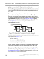
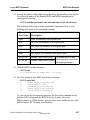
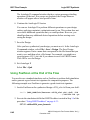
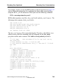
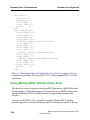
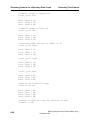
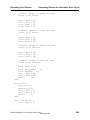
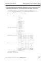
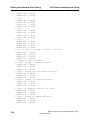
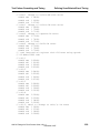
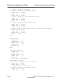
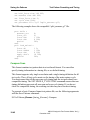
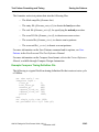
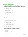
Defining Scan-Related Event Timing
Test Pattern Formatting and Timing
FastScan applies capture or RAM clocks after the primary input pins change state.
Additionally, it measures output pins before the capture clock pulses in the nonscan cycle. The events in each test cycle in a test procedure should follow this
sequence to coincide with the non-scan cycle timing. If the test procedure file
violates this condition, you may have to regenerate test patterns after running the
design rules checker on the modified test procedure.
The following example illustrates this issue:
PROC TEST_SETUP =
FORCE nclk
0
FORCE nclk
1
FORCE nclk
0
FORCE te
1
PERIOD
END;
0;
1;
2;
3;
4;
This test_setup procedure needs only one test cycle. However, the timeplate for
this test procedure does not coincide with FastScan’s non-scan cycle because the
input pin changes after the clock pin NCLK pulses. Thus, you could not use this
test procedure to generate test patterns in a tester format that allows only one
timing definition.
If you modify this test procedure after FastScan produces the pattern set, you will
encounter problems. This is because you cannot change the sequence of test
procedure events after pattern generation and then save patterns with the modified
test procedure file. You can only change the specified times in the test procedures
after pattern generation. In this case, if you modify the test procedure to ensure
consistent timing, you would have to run pattern generation again using the
following modified test procedure:
PROC TEST_SETUP =
FORCE nclk
0
FORCE te
0
FORCE nclk
1
FORCE nclk
0
FORCE te
1
PERIOD
END;
10-6
0;
1;
1;
2;
3;
4;
ASIC/IC Design-for-Test Process Guide, V8.6_1
December 1997