1
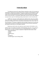
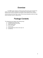
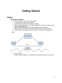
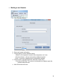
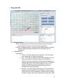
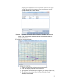
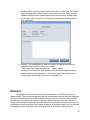
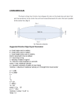
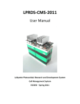
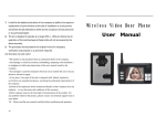
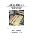
User’s Manual
LPARD-TDF-2012
ECE492 - Spring 2012
Latest Revision Date: 5/7/2012
1
Table of Contents
Contents
Table of Contents....................................................................................................................... 2
Introduction ................................................................................................................................ 3
Overview .................................................................................................................................... 4
Package Contents...................................................................................................................... 4
Getting Started ........................................................................................................................... 5
Setup ...................................................................................................................................... 5
1. Setup base station ....................................................................................................... 5
2. Starting a new Session ................................................................................................ 6
3. Using the GUI .............................................................................................................. 7
Sensors .................................................................................................................................. 9
Wiring Connections: ...........................................................................................................10
Ultrasound Calibration Setup: ............................................................................................10
IR Calibration Setup: ..........................................................................................................10
Origin Setup and Ranging: .................................................................................................10
Safety Guide .............................................................................................................................12
Purpose .................................................................................................................................12
Safety Procedures .................................................................................................................12
Electrical: ...........................................................................................................................12
Environmental: ...................................................................................................................12
Attire: .................................................................................................................................13
Mechanical:........................................................................................................................13
Transportation: ...................................................................................................................13
Other:.................................................................................................................................13
Troubleshooting ........................................................................................................................14
Glossary of Terms.....................................................................................................................15
Service & Warranty Information ................................................................................................16
2
Introduction
The freshwater resources of the planet Earth are essential to quality of life. Accurate and
comprehensive measurements of these resources give us insight into the sustainability of water,
as they help us manage and track pollution. Portable and agile wide-area monitoring of water
quality in hard to reach areas will aid the enforcement of environmental laws as well as the
study of water conservation. The Lafayette Programmable Autonomous River Droid (LPARD) is
an aquatic robotic system for facilitating hydrology measurements in small rivers and creeks.
LPARD is an autonomous, floating platform that stabilizes itself in fast moving, shallow
rivers, while carrying a hydrology and environmental measurement payload achieving absolute
positional and heading motion control, automatically compensating for river current, wind, and
other disturbances. This system is designed to allow two people located on land to quickly and
remotely perform accurate and comprehensive hydrology and environmental measurements
that otherwise would take two or more people to perform.
Measurements will be able to be made day or night, at precise, fixed locations on the
surface of fast moving shallow water without requiring alteration of the river, nor any anchor to
the river bottom, nor a taut line across the river, nor a suspended platform, nor a tether to a
fixed structure, nor wading, nor human occupied boat. Supported measurements include:
• Depth Measurements
• Turbidity
• Imaging
• Dissolved gases
• pH
• Temperature
• Acoustic Doppler Current Profiling (ADCP)
3
Overview
The LPARD system consists of a stationary shore station and a remote controlled boat
platform. The shore station is divided into a controller laptop running Windows 7 with two
separate sensor arrays for triangulation and navigation, an RC controller is also provided for
manual override control. Each tower consists of a sound based triangulation system and a light
based triangulation system for added precision.
Package Contents
The following items are Included in the LPARD package:
● 2 x Tripod Mounted Sensor Arrays
● 1 x LPARD Autonomous River Droid
● 1 x Shore Interface Box
● 2 x 75ft CAT6 cables
● 1 x Folding table
● 1 x 10m or greater tape measure with open reel
● 1 x LPARD.exe
4
Getting Started
Setup
1.
Setup base station
a.
b.
c.
d.
Setup up table in a clear area near the water
Put laptop and shore hardware on table
Connect Shore Hardware into USB port of laptop
Setup tripods equidistant from the shore station with a clear view of the shore at
least 1m away from shore
e. Connect CAT6 cable between the shore hardware and the sensors
f. Measure distance between tripods. Should be as close to 10m as possible.
g. Place the boat on a stable place near the shore. This will be your origin point.
h. Turn on laptop
i. Double click executable icon on desktop. See software installation for more info.
5
2.
Starting a new Session
a. Click File->New Session
b. Enter user’s name and location.
c. Choose speed of sound calibration setting
i.Default - will use speed of sound at room temperature and 1 atm
ii.Previous Session - will use most recently calibrated constant
iii.New - will require a baseline input to automatically calibrate
d. Choose mode of operation(Real-Time, Boat Sim, Sensor Sim)
i.If running in Real-Time: Turn boat on and manually turn tripods to point the
sensors toward the boat.
e. Main GUI window will return.
6
3.
Using the GUI
a. Reading Sensors
i.Boat - Designated area for all sensors which represent status of the boat
such as position, velocity, mode, and internal temperature.
ii.Payload - Designated area for all sensors which represent status of anything
related to taking hydrology measurements such as depth, pH and
temperature.
b. Operating Boat
i.Autonomous
1. Freeze - This is the default mode of operation. This will maintain
the current position of the boat in the water.
2. Ferry - This mode can specify an absolute coordinate(x,y) for the
boat to drive itself to - boat will continue until it reaches its
location. This can be specified by text input of the coordinates in
the upper right hand corner followed by clicking ‘GO’. The desired
path will then appear on the situational display. If there is an
obstacle, manual mode will be required to circumvent this
obstacle(see manual mode below).
3. Scripting - This mode allows the specification of a combination of
ferry and freeze commands. Ferry will require an input of x and y.
freeze will require a time. Additionally, recording can be specified
for each command. All scripts are saveable as ‘.script’ files. These
7
scripts can be loaded for use at a later date. *Note: Do not open
‘.script’ files outside the program or they may become corrupt”
(Script window can be seen below)
ii.Manual - This mode will override all other modes of operation via a remote
control. This is meant as a failsafe as well as a more direct means of
control for the boat.
iii.Reading the situational display -
1.
2.
3.
4.
Display will keep track of previous boat movements
It will also display projected boat movements
All coordinate commands will be logged in the System Output Log
The ability to clear all path lines is under Settings->Graph
Settings->Clear Graph
8
c. Recording Data - To record data click the record button on the GUI. The GUI will
begin recording data of all the sensors for as long as you wish. When you are
satisfied with the duration of data collected click stop recording. Another dialog
box will open with an area for you to decide to insert notes to correspond with
your saved data.
d. Logging - The recorded data of each new session of logging (each time the
program starts) creates a new file of the format:
"Logs/<date time>/<log element name> - <date> <time>"
All logs can be found in the Logs directory. Each log element also has its own
directory within the Logs directory i.e. the system log is found in the directory
"Logs/system/" and the gps log is found in "Logs/gps/" etc.
Sensors
The ultrasound and IR setup consists of six transducers, an IR LED, and two quad
photodetectors. There are two transducers and one photodetector on each of the two tripods as
well as two transducers and one LED located on the boat’s circuitry. The basic theory behind
the sensors is to set up the two tripods on the shore that will form the other two vertices of a
triangle (with the boat’s transducers and LED being the third). Based on the amount of time that
the ultrasonic signal takes to get from a shore transducer to the boat and back, we can calculate
two ranges: one from each tripod to the boat. Assuming a 2D system, we can therefore
9
extrapolate the (x,y) coordinates of the boat relative to the tripods. We can also use the azimuth
and elevation angles that are found via the IR system along with the ultrasound ranges in order
to extrapolate the (x,y) coordinates from each of the tripods. In order to do either of these, we
need to calibrate the sensors to determine the speed of sound on the specific day of use and to
define an origin point for the system to work off of.
Wiring Connections:
The first thing that needs to be done is that the tripods have to be connected to the laptop and
given power.
1. Connect the ultrasound sensor circuitry to the top of each tripod if they are not already
attached.
2. Run the two power line cables that connect the 18V power supply to each of the
ultrasonic tripods.
3. Connect one end of the I2C line to interface J4 on the backend board of the AZ/EL
positioner and the other end to the I2C to USB converter. Then, plug the I2C to USB
converter into laptop.
Ultrasound Calibration Setup:
1. Place the two tripods approximately 5 feet from the end of the shore line and a distance
of 2 meters apart from one another. Tripod 2 should be on the right and tripod 1 should
be on the left. Set the height of each of the tripods so that they are approximately the
same height as one another.
2. Measure the exact distance from sensor face to sensor face using a tape measure.
3. Open the SCADA program located on the laptop’s desktop and plug the measured
distance into the “baseline distance” field by creating a new session and clicking on “new
speed of sound.” Press the “Calibrate” button, which will cause the motors to turn the
ultrasound sensors towards each other and then make them communicate and calculate
the speed of sound.
IR Calibration Setup:
1. After calibrating ultrasound, press the “Calibrate IR” button, which will give the user
manual control of each AZ/EL positioner. BE SURE TO PLACE THE BOAT AT
DESIRED ORIGIN AND POWER ON BOAT IR BEACON!
2. Use the control stick on each AZ/EL to manually aim the photodetector assembly
towards the beacon, the lock LED on the photodetector assembly will light up when it is
within range of the beacon at which point you can stop adjusting. REMEMBER TO DO
THIS FOR THE OTHER AZ/EL!
3. Once both photodetector assemblies are locked onto the beacon, press the “Done IR”
button which will switch the AZ/EL positioners to control loop mode where a control loop
on the AZ/EL’s microcontroller will automatically track the beacon.
Origin Setup and Ranging:
1. Twist the sensors so that they are now facing perpendicular to the river and parallel to
one another without changing the baseline distance between.
10
2. Place the boat at the shoreline at the position that you want the origin to be, and then
press the “Start Ranging” button on the laptop.
3. From this point out, the laptop will record ranging from the ultrasound sensors at the
specified rate. There are no other commands that the user must send via laptop. The
user only has to make sure the boat is in the water at a depth safe enough to start
maneuvering and begin moving the boat via manual or autonomous control.
**Has yet to include error messages from the software during calibration and ranging.
11
Safety Guide
This section will contain a detailed safety guide, including all necessary preparations and
procedures. This will include both on-the-water and off-the-water safety. Necessary safety
equipment will also be detailed.
Purpose
The purpose of this safety plan is to present information and rules that will help in the
prevention of injury or serious harm while using the LPARD-TDF-2012 system. This safety plan
is not all inclusive, but is meant to inform the user so as to prevent the vast majority of injuries.
The system designers and manufacturers are by no means responsible for any injuries that
occur during the use of the LPARD-TDF-2012 system if the items within the this safety plan and
supplemental User’s Manual are not abided by.
Safety Procedures
Electrical:
●
●
●
●
●
Keep electrical equipment (laptop, shore power supply, shore sensors, etc. at least 20
feet away from any water source to avoid possible electrocution and equipment damage.
If electrical components smell like they are burning, power down the system as soon as
possible and do not touch any electrical components because they might be extremely
hot and cause burns.
Malfunctioning electrical components run the risk of catching on fire. If the boat or any
subsystem catches on fire, do not throw water on any system that is powered up.
Proceed with caution when putting out electrical fires and avoid contact with flame.
Powering up: If the boat is being powered in maintenance mode, keep the power cord
and electrical output free of any possible water sources that could cause electrical
shock.
Check electric components often for visible problems and have spare fuses ready at all
times.
Environmental:
●
●
●
●
While the LPARD-TDF-2012 system is designed to operate in suboptimal conditions, it is
recommended that the system is not used when in poor weather conditions. Check
wheather forecasts before planning and trip and consistently keep an eye on the sky to
make sure that there are no developing clouds or storms. Lighting storms and extremely
windy conditions can cause suboptimal conditions that could result of serious injury.
Shore equipment should be setup and operated on a relatively flat surface so that the
equipment as well as the user are able to operate on stable ground.
Be sure to survey the shore station setup area and do not set up the shore station in an
area that at risk of falling rocks or tree limbs.
If you must step into the water to position or pick up the boat, make sure that there are
not submerged objects that can possible cause physical harm.
12
●
Take precautions to limit the amount of UV exposure due to the sun. It is recommended
to wear sunscreen if planning on operating the system for a prolonged period of time.
Attire:
●
Proper footwear should be used when setting up and operating the LPARD-TDF-2012
system. The shores of rivers, creeks and streams are uneven and often difficult to
navigate. Inappropriate footwear will greatly increase the risk of slipping or falling.
Mechanical:
●
●
●
●
●
At no point should hands or fingers be placed near the propulsion components when the
system is powered on. If the propulsion system gets dirty or jammed, be sure to power
the system down before attempting to clean or handle the boat.
Malfunctions are always possible. If the propulsion system goes down while the boat is
on the water, try to avoid getting in the water to retrieve it. It this is absolutely necessary
to enter the water, wear a flotation device.
Do not operate the boat in manual or autonomous mode in a location where there is a
chance of hitting other boats or swimmers. Survey the area both upstream and
downstream to make sure that no one has a possibility of getting hit.
Do not steer the boat towards protruding rocks or trees in the water. If the objects are
visible, use manual mode to ensure that the boat does not accidentally hit an object and
cause damage.
Do not attach external objects to the boat that the boat is not specifically meant to carry
that can add extra weight or cause the boat to become overloaded or unbalanced.
Transportation:
●
●
While transporting the LPARD-TDF-2012 system, make sure that the boat and all other
required equipment are properly fastened to the vehicle. Do not use straps or cables that
are partially torn or show excessive wear.
Use an appropriate vehicle to transport the entire system. Do not position any system
parts in the vehicle that will obstruct the driver’s view.
Other:
●
●
●
●
●
While the system is designed to have the ability to be operated by a single person, it is
recommended to not work alone in isolated areas. Someone should be kept within
earshot at all times since cell phone carriers’ are not available at all locations.
Even though it is not entirely necessary, it is recommended that a lifeguard/EMT certified
individual present in case of an emergency.
Do not launch the boat from a dock or launch ramp while other boats are trying to dock /
cast off.
If planning on operating the system at nighttime, have a flashlight ready so that it is
possible to navigate obstacles on the shore safely.
Depending on the location of operation, always be aware of dangerous wildlife that may
be present.
13
Troubleshooting
This section will contain frequently asked questions and answers, as well as detailed
descriptions of predicted common issues with the system. Walkthroughs will be provided for the
common top-level issues, while more technical issues will refer to the maintenance manual.
●
●
●
If the AZ/ELs do not respond during calibration, first check the green LED on the front
end board of the setup (board with the ultrasonic transducers). If this LED is not green,
then check all the power connections to make sure the system is power up correctly.
○ 18 volts is supplied to the shore station.
○ The 7 meter long I2C cable is correctly plugged into the tripod stand
○ The 4 pin connector from the tripod stand is correctly plugged into the backend
board with the white pin going to pin one of the backend board (pin 1 is the pin
with an arrow pointing at it).
If the LED was already green, then the system is already powered up correctly and the
I2C is not working properly. To fix this, unplug the 18 volt power cord from the shore
station and plug it back in. This will reset I2C connection.
If the range measurement always produces a value that is much shorter than expected
(approximately 1 meter every time), the ultrasound system is likely triggering off of an
unknown source. Check the “receive” LED on the malfunctioning tripod labeled D6. If
this LED is flickering, then rotate the trimpot clockwise until the LED is no longer
blinking. If the LED flickering intensifies, then the trimpot should be turned in the
opposite direction. Turn the trimpot just far enough so that the LED turns off and no
further since turning the trimpot farther than necessary will reduce the range of the
ultrasonic ranging system.
If the ranges recorded are consistently reported as large numbers (68 meters), then the
boat is out of range for the ultrasonic ranging system and there is nothing the user can
do to fix this. The boat will rely on GPS at this point now.
14
Glossary of Terms
This section will contain a list of non-obvious common terms that may be referred to in
this document. These terms will mostly describe parts of the system that the user may not be
familiar with.
15
Service & Warranty Information
This section will contain the End User License Agreement and anything else deemed
necessary to cover ourselves legally, in terms of responsibility, liability, etc. A link to the project
website could be provided for the user if they would like more information.
16