1
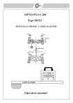
User’s manual for the digital
electronic controller JET II
Page 1 of 16
Page 2 of 16
TECHNICAL CHARACTERISTICS
This controller incorporates a microprocessor-based technology with its corespondent
control software, providing it with special characteristics and the possibility to
incorporate other important innovative improvements later on.
This controller differs from others by not adjusting the voltage but the frequency,
resulting in having always the same voltage on track. What it does is to push this
voltage to control the motor. This system allows the motors to have a greater torque at
few revolutions and in addition improves the power deliverance on dirty surfaces
(rallies with flower, etc...).
Another important difference from the conventional controllers is that it does not use
any resistance where we must regulate the Ohm. In this unit we choose the sensibility
curve of the controller allowing us to have more or less sensibility at each point of the
trigger stroke.
The controller is equipped with a eight combinations pre-selector that allows us to
choose among the sensibility curves that we have stored at that time. The serial curves
permit great variety of vehicles, going from rally type to G12 in speed.
The trigger uses 15 positions, which allows the application of 15 different powers
giving the sensation of smoothness and continuity while driving.
Page 3 of 16
CHARACTERISTICS’ SUMMARY
-
It stands up to 10 Amp in continuous and pikes of 20 Amp.
Valid for tensions between 8 and 24 Volts.
Control by Pulse Width Modulation (PWM)
8 stores sensibility curves.
Braking power regulation.
Interchangeable contact plate, longer live.
Light weight
The maximum tension applied to the car is the circuit’s one, there are no internal falls
due to the semi-conductors.
CONNECTION TO THE TRACK
For its connection to the track it uses three cables with standard banana conductors,
following the colors’ chart used by the Parma controllers.
Banana white cable
Banana red cable
Banana black cable
=
=
=
positive proceeding from feeding source
brake
trigger (positive to motor)
VERY IMPORTANT !!!
In some countries different type of codifications by colors are used, therefore, it is very
important before connecting the cables to check the codification used in the county and
the equivalencies with our colors. If a wrong connection is performed we could damage
the controller and the track.
To avoid damaging the controller in case the connections do not follow the standard
color code, first we will connect the red and white bananas to the track without pushing
the trigger. If the connection is correct the GREEN LED will turn on and we will then
connect the black banana.
Follow allays this procedure in case of doubt when dealing with unknown tracks.
THIS UNIT IS ONLY VALID FOR TRACKS THAT HAVE THE NEGATIVE OF
THE FEEDING SOURCE CONNECTED TO THE TRACK AND THE POSITIVE TO
THE TRIGGER (POSITIVE POLARITY)
Once the connection is done the RED LED will turn on with different intensities when
pushing the trigger more or less. If all that has been mentioned above is operating
correctly, the controller is installed.
Page 4 of 16
SENSIBILITY CURVES
We may select them by means of the eight combinations pre-selector using a small
screwdriver through the openings of the plastic carcass. In the last eight pages we may
visualize the behavior of each one of the combinations and the specialty they are
recommended for.
BRAKING REGULATION
One of the characteristics of this controller is the braking regulation possibility. This
regulation is controlled through a switch and a small potentiometer.
Page 5 of 16
With the switch we may activate or deactivate the braking regulation. With the switch
down we will have the regulation deactivated and therefore the whole brake. With the
switch up we will have the braking regulation activated and we will regulate it through
the potentiometer: turning it clockwise we augment the braking power and turning it on
the contrary sense we diminish the braking power.
MAINTENANCE TASKS
Cleaning
Clean the printed circuit zone where the brushes touch with an ear-stick and a bit of
alcohol and then lubricate with grease for contactors.
Lubrication
Lubricate the trigger axe with fine oil for bronze bushes.
Lubricate the graphite contactor surface with grease for contactors, for example the
“Switch Lubricant” grease from Tamiya. It is recommended not to apply too much
grease, with a pair of drops is enough.
Controlling the wearing of the graphite contactor
The part of the trigger slide touching the printed circuit has a graphite contactor. It is
very important to control its wearing in order to avoid the friction between metallic
parts and thus to avoid damaging the track.
When this graphite contact is very worn out we must proceed to replace it following the
instructions stated here next.
First of all we will disassemble the trigger loosening the nut marked on the photograph.
Page 6 of 16
Once the trigger is loose we will take out the worn graphite and replace it by the new
one.
To fix the graphite it is not necessary to use adhesive because the pressure of the cursor
on the contacts’ plate does not let it move. However, if you would like to fix it for
security reasons, you may do it using a very little amount of cianocrilate adhesive.
In case of excessive adhesive application we may loose the conductivity. If this happens
we should clean the cursor with cianocrilate adhesive cleaning liquid.
Once replaced the graphite, we will proceed to reassemble the trigger to its original
position.
VERY IMPORTANT !!!
Once the graphite has been replace, we must adapt the new one to the contact surface. If
we don’t do this correctly we might damage the contact plate.
To proceed with this adaptation we will cut a piece of very fine surface sand paper of
approximately 45 x 11 mm and place it under the contactor, as shown on the
photograph.
We will perform several forward-backward movements with the trigger to achieve a
perfect adaptation and a minimum friction.
Page 7 of 16
Contact plate replacement
Due to the wearing after time passes by or to the non-replacing of a worn graphite, the
contact zone of the graphite with the printed circuit may suffer irregular wearing or
damages that would translate into an erratic performing because of the contact failure.
To solve this problem this controller is equipped with an interchangeable contact plate
attached to the main plate by two screws.
If we observed that the contact plate is damaged, we would proceed to replace it by a
new one as follows:
- We would loosen the contact plate’s fixing screws.
- We would next take out the damaged plate.
- Finally we wold position the new one on its place and then screw it back tight.
Page 8 of 16
PROBLEMS SOLVING
Before diagnosing any failure make sure of the following:
- The cables and bananas that are connected to the track are in good shape (meaning
they have continuity)
- The slide’s graphite pressure on the contact plate is the correct one.
- The graphite contactor is in good shape.
- The contact zone of the printed circuit is clean.
All is correct but the vehicle does not brake.
- Check that the thick cable going from the trigger to the printed circuit is not damaged.
- Check that the metallic “U” of the trigger touches correctly the metallic stop when in
the rest position.
When the braking regulation is activated, the vehicle does not brake at all, even
when regulated at the maximum brake position.
-
The potentiometer or the braking regulation’s chip might be damaged. You must
send the controller back to the Distributor for its reparation.
The controller is correctly connected, the green led on, when pushing the trigger
the red led turns on increasing its intensity but the vehicle remains still.
-
The pulsation’s control chip (MOSFET) might be damaged. You must send the
controller back to the Distributor for its reparation.
The controller is correctly connected, the green led on, when pushing the trigger
the red led turns on increasing its intensity but the vehicle only moves at maximum
power even when the trigger is at the minimum power position.
-
The pulsation’s control chip (MOSFET) might be short-circuited. You must
send the controller back to the Distributor for its reparation.
The controller is correctly connected, the green led on, when pushing the trigger
the red led does not turn on and the vehicle remains still.
-
The controller’s processor might be damaged. You must replace it by a new one.
The processor is connected to the main plate of the controller by means of a
base. To take it out you must only pull it out.
Before touching the new processor, try to touch a metallic item in contact with
the floor in order to discharge the static electricity.
To fit in the new processor you must make sure that the mark on it coincides
with the mark of the base.
Page 9 of 16
The controller is correctly connected but the green led doesn’t turn on and the red
one doesn’t either when pushing the trigger.
-
Problem due to an unknown cause, you must send the controller back to the
Distributor for its reparation.
Page 10 of 16
Flux for the problems’ diagnosis.
Page 11 of 16
Graphics for the originally programmed curves
Curve nº 1 Wooden track 16D, S16D
Curve nº 2 Wooden track 16D slow, Model Cars Fast
Page 12 of 16
Curve nº 3 Wooden Track Model Cars, TSFR
Curve nº 4 Model Cars, TSRF, Magnetic
Page 13 of 16
Curve nº 5 Plastic track Magnetic, High rpm motors
Curve nº 6 Plastic Track no magnets and low rpm motors
Page 14 of 16
Curve nº7 Plastic Track no magnets and low rpm motors
Curve nº 8 Plastic Track no magnets and low rpm motors slow
Page 15 of 16
Product manofactured by:
DESARROLLOS TECNOLÓGICOS PARA MODELISMO, S.L.
P.O. BOX 4
08480 L’Ametlla del Vallés
Barcelona (Spain)
Fax : +34 938431882
Web: www.franspeed.com
e-mail : [email protected]
Distributed in theUnited Kigdom by :
Page 16 of 16