1
172
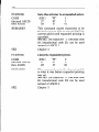
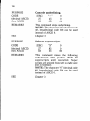
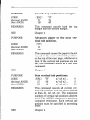
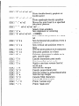
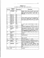
Pin 11 reports when the printer is not able to receive data.
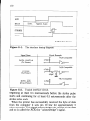
The signal is called BUSY. When this signal is high, the printer
cannot receive data. This signal will be high during data
transfer, when the printer is off-line and when an error condition exists.
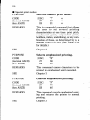
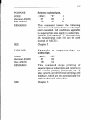
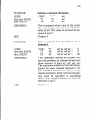
The printer will report that it has run out of paper by making
the PAPER OUT signal on pin 12 high. This pin can be held low
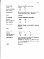
by turning DIP switch l-5 off. When the printer is in the on-line
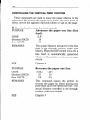
state, pin 13 is held high. This signal (SELECTED) tells the
computer that the printer is ready to receive data.
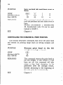
Pins 14, 15,34-36 are not used, while pins 16, 17, 19-30 and 33
are grounded. Pin 18 is connected to the + 5VDC cupply in the
printer.
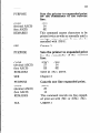
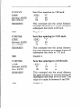
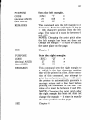
Pin 31 can be used to reset the printer. If this siganl (RESET)
goes low the printer will reinitialize. Pin 32 is used to report error conditions in the printer. This signal (ERROR) is high during normal operation and goes low to report that the printer cannot print due to an error condition.