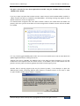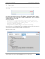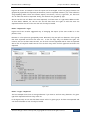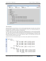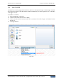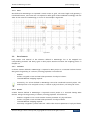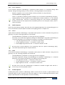
1
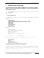
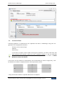
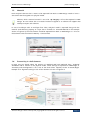
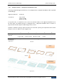
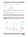
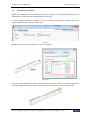
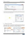
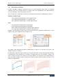
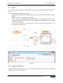
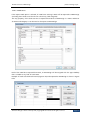
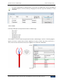
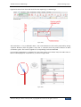
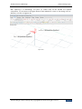
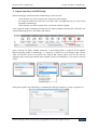
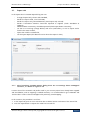
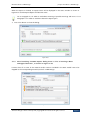
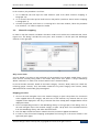
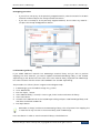
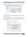
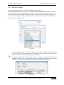
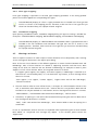
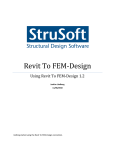
StruSoft StruXML Revit Add-In
Manual: Using Revit – FEM-Design link
StruSoft AB
Fridhemsvägen 22
SE-217 74, Malmö, Sweden
www.strusoft.com
Version: August 27th, 2015
Copyright
Copyright© 2015 by StruSoft. All rights reserved.
Content of this publication may not be reproduced or transmitted in any means without the
written permission of Structural Design Software in Europe AB.
Trademarks
FEM-Design ® is a registered trademark of StruSoft. Revit ® is a registered trademark of Autodesk.
Disclaimer
The StruSoft StruXML Revit Add-In is a tool that enables a link between Revit and FEM-Design.
However, the user must understand the assumptions and restrictions that are described in this
document.
Considerable time and effort have gone into development and testing of the StruSoft StruXML
Revit Add-In. We have done our best to ensure the reliability of the software and the accuracy of
this document. However, the user must accept that no warranty is given by the developers or
distributors concerning accuracy of this software or information found in this document.
Anyone that has doubts concerning the accuracy of the StruSoft StruXML Revit Add-In, or has
suggestions regarding development of the StruSoft StruXML Add-In, is welcome to contact us at:
[email protected].
For support, please use: [email protected]. When sending support question, please
remember to always attach an original Revit / FEM-Design model, struxml file, and in case of
Import to Revit – a Revit rvt file, as well us explain which version of FEM-Design and StruSoft
StruXML Revit Add-In have been used.
Current link versions
-
StruSoft StruXML Revit 2015 Add-In 1.1.004 (32 or 64 bit)
StruSoft StruXML Revit 2016 Add-In 1.1.004 (32 or 64 bit)
Compatibility
-
Revit/Revit Structure: version 2015 and 2016 (32 or 64 bit)
FEM-Design 11.01.002 or higher; the recommended version is 13.01.003 (to take
advantage of all the features offered by the link)
Download
-
FEM-Design Download Center
StruSoft Installer
Tutorials and Tips and tricks
-
FEM-Design – Revit Integration
StruSoft blog
StruSoft Official YouTube channel
Table of contents
I. INTRODUCTION ................................................ 1 4.3. IMPORT STRUXML FILE TO REVIT............................. 43
4.4. MAPPING ........................................................... 46
II. WORKFLOW: REVIT TO FEM-DESIGN ................ 2 4.5. WARNINGS AND ERRORS....................................... 50
1. DATA EXCHANGE SCOPE ........................................ 2
1.1. STRUCTURAL COLUMNS AND FRAMING ELEMENTS ....... 2
1.2. STRUCTURAL FLOORS ............................................. 3
1.3. STRUCTURAL WALLS ............................................... 4
1.4. STRUCTURAL FOUNDATIONS ................................... 5
1.5. MATERIAL ............................................................ 7
1.6. ECCENTRICITY IN SHELL ELEMENTS ............................ 7
1.7. ECCENTRICITY IN BEAMS ....................................... 10
1.8. RELEASES OF LINEAR ELEMENTS ............................. 11
1.9. BOUNDARY CONDITIONS ....................................... 12
1.10. GRIDS.............................................................. 13
1.11. LEVELS............................................................. 14
1.12. LOADS AND LOAD CASES ..................................... 14
2. EXPORT FROM REVIT TO FEM-DESIGN.................... 19
2.1. EXPORT TAB ....................................................... 20
2.2. MATERIALS MAPPING........................................... 22
2.3. SECTIONS MAPPING ............................................. 25
2.4. WARNINGS AND ERRORS ...................................... 27
2.5. EXPORT REPORT .................................................. 33
2.6. OPEN STRUXML ................................................. 36
III. WORKFLOW: FEM-DESIGN TO REVIT ............. 37
3. DATA EXCHANGE SCOPE ...................................... 37
3.1. DATUM ELEMENTS............................................... 37
3.2. BAR ELEMENTS.................................................... 38
3.3. SHELL ELEMENTS ................................................. 39
3.4. PROFILED PANELS ................................................ 39
3.5. FOUNDATIONS .................................................... 40
3.6. SUPPORTS .......................................................... 41
3.7. LOADS AND LOAD CASES ....................................... 42
4. IMPORT FEM-DESIGN MODEL TO REVIT .................. 43
4.1. REQUIREMENTS: ................................................. 43
4.2. EXPORT FEM-DESIGN MODEL TO STRUXML FILE ....... 43
Introduction
I.
Introduction
The transfer of data between Revit and FEM-Design is possible thanks to the StruSoft StruXML Revit
Add-In. Data are saved into a struxml format and the file is exchanged between Revit and FEMDesign. It is not required that both Revit and FEM-Design are installed at the same computer.
Direction: Revit to FEM-Design
-
Export a Revit analytical model to create a new model in FEM-Design.
Export a Revit analytical model to update a model existing in FEM-Design.
Direction: FEM-Design to Revit
-
Import a FEM-Design model to create a new model in Revit.
Import a FEM-Design model to update existing model in Revit*.
UPDATE
EXPORT
IMPORT
UPDATE
* This workflow will be supported starting from StruSoft StruXML Revit Add-In 1.2.001
Manual scope
This document describes the concept behind the link between Revit and FEM-Design and explains
how to exchange data between those two programs using the StruSoft StruXML Revit Add-In
1.01.001.
The manual is divided into two main parts, each dealing with one particular direction of data
exchange. Each part contains description of elements and features that can be transferred, as well as
explanation of the transfer procedure.
Installation
Download the latest version of StruSoft StruXML Revit Add-In, close Revit and run the installation
file. After completion of the installation process, StruSoft FEM-Design panel will appear in the
Analyze tab in Revit along with the Export StruXml and Import StruXml commands as shown in Figure
I-1.
Figure I-1
Structural Design Software in Europe AB | Copyright© 2014 StruSoft. All rights reserved.
Page 1
Workflow: Revit to FEM-Design
II.
| Data exchange scope.
Workflow: Revit to FEM-Design
The transfer of structural elements from Revit to FEM-Design is done by exporting an analytical
model of an instance of an element along with its properties, i.e. material, section/profile/thickness,
release conditions, eccentricity.
If a structural element in Revit does not have analytical model enabled, it will not be exported
to FEM-Design.
1. Data exchange scope
Following elements and properties can be exported from Revit to FEM-Design using the StruSoft
StruXML Revit Add-In:
Elements:
-
Structural Columns
Structural Framing elements (Beams, Beam systems, Braces, Trusses)
Structural Floors
Structural Walls
Structural Foundation
Grids and levels
Loads and load cases
Properties:
-
Material of an element
Section / Profile / Thickness of an element
Releases of linear elements
Boundary conditions
Eccentricity in case of floor slabs, walls and beams
1.1.
Structural columns and framing elements
Following properties of Structural Columns and Structural Framing elements are exported from Revit
to FEM-Design along with the geometry of the Analytical Column or Analytical Beam element:
-
Section / profile
Material*
Release conditions
Eccentricity (only of beams)**
* Only the Structural material is exported. Read more in Chapter 0.
** Read more about the eccentricity export rules in Chapter 1.7.
Slanted columns in Revit can be exported to struxml and read in FEM-Design, but a message at the
export will appear (both in the Export dialog and in the Export Report) in order to warn about
slanted elements in the model, as shown in Figure II-1.
Structural Design Software in Europe AB | Copyright© 2014 StruSoft. All rights reserved.
Page 2
Workflow: Revit to FEM-Design
| Data exchange scope.
Figure II-1
1.2.
Structural floors
Following properties of Structural Floors are exported from Revit to FEM-Design along with the
geometry of the Analytical Floor element:
-
Thickness of the structural layer
Material*
Eccentricity**
If one wants to export a Revit model containing floor elements, he needs to be aware that
each structural floor element in Revit has to be a separate instance i.e. only one individual
floor should be drawn using the Create Floor Boundary command as shown in Error!
Reference source not found..
If more than one floor element is created within one floor boundary (as shown in Figure II-2), it will
be divided into number of separate elements when exported to struxml.
Figure II-2
* Only the Structural material is exported. Read more in Chapter 0.
Structural Design Software in Europe AB | Copyright© 2014 StruSoft. All rights reserved.
Page 3
Workflow: Revit to FEM-Design
1.3.
| Data exchange scope.
Structural walls
Following properties of Structural Walls are exported from Revit to FEM-Design along with the
geometry of the Analytical Wall element:
-
Thickness of the structural layer
Material*
Eccentricity**
* Only the Structural material is exported. Read more in Chapter 0.
** Read more about the eccentricity export rules in Chapter 1.6.
Revit
Figure II-3
Curved walls drawn in Revit (Figure II-3) will be divided into a number of straight walls while
being exported to struXML file, as shown in Figure II-3. This is the way curved walls are
represented in FEM-Design.
Figure II-4 shows the convention of the local coordinate system that curved walls will be assigned
with in FEM-Design.
FEM-Design
Figure II-4
Structural Design Software in Europe AB | Copyright© 2014 StruSoft. All rights reserved.
Page 4
Workflow: Revit to FEM-Design
1.4.
| Data exchange scope.
Structural Foundations
User can decide if to export Structural Foundations as supports or as foundation elements. By default,
foundations are always exported as foundation elements. The option to export foundations as
supports is present in the StruXML Export dialog as shown in Figure II-5.
Figure II-5
Structural Foundations can be exported as foundation elements only to FEM-Design in version
higher than 12.00.003
1.4.1. Export as foundation elements
If Foundation as Supports option is not selected, Structural Foundations will be exported from Revit to
FEM-Design as foundation elements according to the following manner:
Structural Foundation: Isolated
It is exported to FEM-Design as Isolated foundation with the following default settings:
-
Analytical system: Point support group
Bedding modulus: 10000 kN/m2/m
An analytical model of isolated foundation is exported to FEM-Design along with the material
properties and the exact position of the physical model in respect to the analytical model (In FEMDesign recognized as Connection point) as shown in Figure II-6.
Revit
EXPORT
FEM-Design
Figure II-6
Structural Design Software in Europe AB | Copyright© 2014 StruSoft. All rights reserved.
Page 5
Workflow: Revit to FEM-Design
| Data exchange scope.
it is only possible to export the geometry of foot pads with non-curved edges. All the other
kinds of isolated foundations, i.e. foot pads with round edges, piles, pile caps, etc. will be
exported as a Point Support group with the default state Hinged. The point support will be
added in each analytical foundation (point).
Structural Foundation: Wall
It is exported to FEM-Design as Wall foundation with the following default settings:
-
Analytical system: Line support group
Bedding modulus: 10000 kN/m2/m
An analytical model of wall foundation is exported to FEM-Design along with the material properties
and the exact position of the physical model in respect to the analytical model (in FEM-Design
recognized as Insertion point) as shown in figure below.
Revit
EXPORT
FEM-Design
Figure II-7
Structural Foundation: Slab
It is exported to FEM-Design as Foundation slab with the following default settings:
-
Bedding modulus: 10000 kN/m2/m
An analytical model of slab foundation is exported to FEM-Design along with the material properties
and the analytical alignment definition. Read about the analytical alignment rules in Paragraph 1.6.
1.4.2. Export as supports
If Foundation as Supports option is selected, Structural Foundations are exported from Revit to FEMDesign as Supports according to the following manner:
-
Structural Foundation: Isolated in FEM-Design will be converted into Point Support Group with
the default type: Hinged
Structural Foundation: Wall in FEM-Design will be converted into Line Support Group with the
default type: Hinged
Structural Foundation: Slab in FEM-Design will be converted into a Surface support group.
Structural Design Software in Europe AB | Copyright© 2014 StruSoft. All rights reserved.
Page 6
Workflow: Revit to FEM-Design
1.5.
| Data exchange scope.
Material
Each analytical element that is meant to be exported from Revit to FEM-Design needs to have a
structural material assigned to its physical model.
Element, which structural material is set to be <By Category> will not be exported to FEMDesign. An error about lack of structural material assigned to an element will appear after
attempt to export such element.
In case of multilayer walls or multilayer floor slabs, analytical model is exported along with the
material (and thickness) property of a layer that is marked as a Structural Material. In the example
shown in Figure II-8, the wall element would be exported from Revit to FEM-Design as a 215 cm
thick element with the material: Masonry – Concrete Block.
Figure II-8
1.6.
Eccentricity in shell elements
In Revit user can decide about the position of Analytical Wall and Analytical Floor / Analytical
Foundation Slab in relation to the physical model. Those settings are exported to FEM-Design as
Eccentricity and the Alignment is set to one of the three values: Top/Left, Center or Bottom/Right.
Example of an alignment setting in case of floor element is shown in Figure II-9.
Revit
EXPORT
FEM-Design
Figure II-9
Structural Design Software in Europe AB | Copyright© 2014 StruSoft. All rights reserved.
Page 7
Workflow: Revit to FEM-Design
| Data exchange scope.
1.6.1. Analytical Floor / Analytical Foundation Slab
Following Analytical Alignment definition of an Analytical Floor / Analytical Foundation Slab is exported
to FEM-Design:
Alignment Method:
Projection
z Projection:
Top of Slab
Center of Slab
Bottom of Slab
In any other case, i.e. Projection is set to a Level or a Reference Plane, or the Alignment Method is set to
be Auto detect, the default position of Analytical Floor / Analytical Foundation Slab in relation to
physical element after export to FEM-Design will be: Center.
Example of different settings in Revit and the final result after opening the exported model in FEMDesign is shown in Table II-1 and in Figure II-10.
Revit Alignment
Method:
Corresponding
FEM-Design
alignment
1
Projection
2
Projection
3
Projection
4
Projection
5
Auto detect
Top of Slab
Center of Slab
Bottom of Slab
Level 1
-
Top/Left
Center
Bottom/Right
Center
Center
Table II-1
Revit
EXPORT
FEM-Design
Figure II-10
Structural Design Software in Europe AB | Copyright© 2014 StruSoft. All rights reserved.
Page 8
Workflow: Revit to FEM-Design
| Data exchange scope.
1.6.2. Analytical Wall
Following Analytical Alignment settings of an Analytical Wall are exported to FEM-Design:
Alignment Method:
Projection
Projection:
Center of Element
Interior Face
Center of Core
Exterior Face
In any other case, i.e. Projection is set to a Grid or a Reference Plane or the Alignment Method is set to
be Auto detect, the default position of analytical model in relation to physical element after export to
FEM-Design will be: Center.
Example of different settings in Revit and the final result after opening the exported model in FEMDesign is shown in Table II-2 and in Figure II-11.
Revit Alignment
Method:
Corresponding
FEM-Design
alignment
1
Projection
2
Projection
3
Projection
4
Projection
5
Auto detect
Center of
Element
Interior Face
Center of Core
Exterior Face
-
Center
Right
Center
Left
Center
Table II-2
Revit
EXPORT
FEM-Design
Figure II-11
Structural Design Software in Europe AB | Copyright© 2014 StruSoft. All rights reserved.
Page 9
Workflow: Revit to FEM-Design
1.7.
| Data exchange scope.
Eccentricity in beams
Almost any configuration of analytical beam model in regards to its physical representation can be
transferred to struxml and read in FEM-Design as Eccentricity.
In order to export eccentricity in beams, one has to check the Export beam eccentricity box in the
Export StruXML dialog, as shown in Figure II-12.
Figure II-12
Example of beam eccentricity export is shown in Figure II-13
EXPORT
Figure II-13
The eccentricity configuration that cannot be exported to struxml is when the start and end part of
the analytical beam are not the same. Example of such configuration is shown in Figure II-14.
Figure II-14
Structural Design Software in Europe AB | Copyright© 2014 StruSoft. All rights reserved.
Page 10
Workflow: Revit to FEM-Design
| Data exchange scope.
In this case, a warning will be thrown at the export (Figure II-15).
Figure II-15
The analytical position of the beam will be exported to struxml (as usually), but eccentricity will not.
It means that the cross section will be simply assigned along the length of the analytical beam, with
y’=0 and x’=0 eccentricity values (Figure II-16).
Figure II-16
1.8.
Releases of linear elements
All linear analytical elements are exported from Revit to FEM-Design along with the settings of Top
Release and Bottom Release. The exact definition of the three predefined releases: Pinned, Fixed,
Bending Moment as well as User Defined release are exported to FEM-Design. Figure II-17 shows
release conditions originally set in Revit and the result of the export to FEM-Design.
FEM-Design
Revit
EXPORT
Figure II-17
Structural Design Software in Europe AB | Copyright© 2014 StruSoft. All rights reserved.
Page 11
Workflow: Revit to FEM-Design
1.9.
| Data exchange scope.
Boundary conditions
In Revit, Boundary Conditions command allows to choose between three kinds of boundary
conditions: Point, Line, and Area. User has to assign it with one of predefined or user defined State in
X, Y and Z direction: Fixed, Pinned, Roller, and User.
The exact definition of boundary conditions can be exported from Revit to FEM-Design as follows:
Boundary Condition Type:
-
Point: exported to FEM-Design as Point Support Group
Line: exported to FEM-Design as Line Support Group
Area: exported to FEM-Design as Surface Support Group
State:
-
Fixed: exported to FEM-Design as type Hinged
Pinned: exported to FEM-Design as type Rigid
Roller: exported to FEM-Design according to Revit definition
User: exported to FEM-Design according to Revit definition
Example: Point boundary condition type with the Pinned state is exported to FEM-Design as Point
Support Group, type: Hinged as shown in Figure II-18.
Revit
FEM-Design
EXPORT
Figure II-18
The “Rigid” value exported from Revit to FEM-Design is equal to: 1e+15 kN/m for motion, and
3.046e+11kNm/° for rotation.
Line boundary conditions under curved walls are special case. Each curved wall exported from Revit,
in FEM-Design will be divided into a number of straight walls. But line boundary condition will
remain curved, as shown in the left part of the figure below. It is therefore, user’s responsibility to
verify the support condition under curved walls in order to obtain a desired solution as shown in the
right part in figure below.
Figure II-19
Structural Design Software in Europe AB | Copyright© 2014 StruSoft. All rights reserved.
Page 12
Workflow: Revit to FEM-Design
| Data exchange scope.
1.10. Grids
Grids defined in Revit model may be exported to FEM-Design where they will be recognized as Axes.
Grids are exported with following assumptions:
-
If the option to Export Grids (Figure II-23) is selected, all the grids will be exported to FEMDesign.
The exact length of the each grid is exported.
All the grids are always exported into 00.000 m level in FEM-Design.
Names of the grids are not exported. Each axis in FEM-Design will receive a new number
based on the order of grid creation in Revit, as shown in Figure II-20. If necessary, renaming
can be performed in FEM-Design.
Revit
FEM-Design
EXPORT
Figure II-20
In FEM-Design only straight line axes are allowed. Therefore,
-
Multi-Segment Grid after export from Revit to FEM-Design will be replaced with a number of
straight line axes equivalent to number of segment.
curved grid after export from Revit to FEM-Design will be replaced with a straight line axis
between the start and end point of the original curved grid, as shown in Figure II-21.
FEM-Design
Revit
EXPORT
Figure II-21
Structural Design Software in Europe AB | Copyright© 2014 StruSoft. All rights reserved.
Page 13
Workflow: Revit to FEM-Design
| Data exchange scope.
1.11. Levels
Levels defined in Revit model can be exported to FEM-Design, where they will be recognized as
Storeys.
Levels are exported with following assumptions:
-
-
If the option to Export Levels is selected (Figure II-23), all the levels will be exported to FEMDesign.
Name of the levels are exported to FEM-Design.
Size of the Storey in FEM-Design is calculated based on the placement of most outer
elements in the Revit model and included as a Horizontal size of building in the Storey dialog,
as shown in Figure II-22.
Levels cannot be exported if no elements are created in the Revit model because size of a
storey cannot be generated.
Revit
FEM-Design
EXPORT
Figure II-22
Figure II-23
1.12. Loads and load cases
In order to export loads and load cases one should select the Loads to be exported in the StruXml
Export dialog, as shown in Figure II-23.
Structural Design Software in Europe AB | Copyright© 2014 StruSoft. All rights reserved.
Page 14
Workflow: Revit to FEM-Design
| Data exchange scope.
1.12.1. Load cases
If the Export Loads option is selected, all Load Cases existing in Revit will be exported to FEM-Design
(including those loads cases that do not contain any loads assigned).
The only property of the load case that is exported from Revit to FEM-Design is a Name. Definition
of Nature and Category is not relevant for the export to FEM-Design.
Figure II-24
Each of the Load Cases exported from Revit, in FEM-Design will be assigned with the Type: Ordinary
that is suitable to any kind of load nature.
Example of loads cases defined in Revit (Figure II-24) and exported to FEM-Design is shown in Figure
II-25.
Figure II-25
Structural Design Software in Europe AB | Copyright© 2014 StruSoft. All rights reserved.
Page 15
Workflow: Revit to FEM-Design
| Data exchange scope.
It is user’s responsibility to decide which of the cases will additionally contain self-weight of
structural elements. It can be done by changing the load case Type from Ordinary to +Struc.
Dead load.
Figure II-26
1.12.2. Loads
Following Load types are exported from Revit to FEM-Design:
-
Point Load
Line Load
Area load
Hosted Point Load
Hosted Line Load
Hosted Area load
The example on how the loads are exported from Revit to FEM-Design is shown in following Figures.
Figure II-27 shows a vertical force of 1kN is applied to a column in Revit. The value of the force is 1kN so the force acts downward. The force is applied into a load case: Dead load.
Figure II-27
Structural Design Software in Europe AB | Copyright© 2014 StruSoft. All rights reserved.
Page 16
Workflow: Revit to FEM-Design
| Data exchange scope.
Figure II-28 shows how the model looks like after exporting it to FEM-Design.
Figure II-28
The load value is –1 kN, as defined in Revit. The correct direction of the load is preserved by setting
a positive direction (with the global Z axis) that is consistent with the positive direction of Revit
coordinate system. The load is assigned to a corresponding load case Dead load.
If more force components is assigned into one point load or one surface load, the visible force in
Revit will be displayed as resultant force, as shown in Figure II-29.
Figure II-29
Structural Design Software in Europe AB | Copyright© 2014 StruSoft. All rights reserved.
Page 17
Workflow: Revit to FEM-Design
| Data exchange scope.
After exporting it to FEM-Design, the point (or surface load) will be divided into separate
components. So, the column from figure above will be loaded with a force of 1kN acting in the X –
direction, as shown in Figure II-30.
Figure II-30
Structural Design Software in Europe AB | Copyright© 2014 StruSoft. All rights reserved.
Page 18
Workflow: Revit to FEM-Design
| Export from Revit to FEM-Design.
2. Export from Revit to FEM-Design
Before exporting a model from Revit to FEM-Design, make sure that:
-
all the elements you wish to export have analytical model enabled,
the analytical model of the structure is consistent and is arranged the way you want it to be
exported to FEM-Design,
all the elements you wish to export have a structural material assigned.
If the analytical model is prepared, proceed with the Export StruXML command that is placed in the
StruSoft FEM-Design panel in the Analyze tab in Revit.
Figure II-31
Upon choosing the Export StruXML command, a Code dialog shown in Figure II-32 will appear.
Before exporting model to FEM-Design, it is necessary to select one of the design codes. Chosen
code and national annex will influence the material and sections library that will be used for
mapping. After choosing the desired code standard, check Set as default box, if you want to save this
choice.
Figure II-32
Upon pressing OK in the Code dialog, a StruXML Export dialog will appear, as shown in Figure II-33.
Figure II-33
Structural Design Software in Europe AB | Copyright© 2014 StruSoft. All rights reserved.
Page 19
Workflow: Revit to FEM-Design
2.1.
| Export from Revit to FEM-Design.
Export tab
In the Export tab of a StruXML Export dialog user can:
-
change the previously chosen Code Standard,
decide if to export Grids, Levels and Loads,
decide if to export only selected elements (check Export only selected)
decide if foundation elements should be exported as supports (check Foundation as
Supports),
Decide if beams eccentricity should be exported (check Export beams eccentricity)
see the list of warnings (orange bullets) and errors (red bullets), as well as export results
listed in the status window,
export the model to struXML file,
see the Export Report (that becomes active when the export is done).
Figure II-34
2.1.1. After launching StruXML Export dialog there are no warnings about unmapped
elements, as shown in Figure II-34.
It means that all the materials and profiles used in your current project have already been mapped
and saved before, and no mapping is needed. However, it is recommended to go to Materials and
Sections tabs in order to check and approve the previously saved mapping.
In this situation, the procedure is as follow:
1. In the Export tab, press an icon with three dots to define location and name of the struxml file.
2. Press the Export button to export the model into struxml file.
Structural Design Software in Europe AB | Copyright© 2014 StruSoft. All rights reserved.
Page 20
Workflow: Revit to FEM-Design
| Export from Revit to FEM-Design.
When the export is finished, an export status will be displayed in the status window as shown in
Figure II-35 and the Export Report will become active.
Go to Paragraph 2.4 in order to read about meaning of possible warnings and errors. Go to
Paragraph 2.5 in order to read more about the Export report.
3. Press Close button to close the dialog.
Figure II-35
2.1.2. After launching StruXML Export dialog there is a list of warnings about
unmapped elements, as shown in Figure II-36.
It means that all or some of the materials and/or sections included in the Revit model have to be
mapped to the corresponding materials/sections in FEM-Design.
Figure II-36
Structural Design Software in Europe AB | Copyright© 2014 StruSoft. All rights reserved.
Page 21
Workflow: Revit to FEM-Design
| Export from Revit to FEM-Design.
In this situation, the procedure is as follow:
1. Go to Materials tab and map the listed materials (read more about materials mapping in
Paragraph 2.2).
2. Go to Sections tab and map the listed sections and profiles (read more about sections mapping
in Paragraph 2.3).
3. Go back to Export tab, and if there is no warning left in the status window, follow the procedure
from workflow 1 in order to export the model.
2.2.
Materials mapping
In order to map the materials included in the Revit model one should move to Materials tab, shown
Figure II-37. The dialog is divided into two parts: Revit materials in the left part and FEM-Design
materials in the right part.
Figure II-37
Only current items
You can decide if you want to see (and map) all the materials from the Revit model library or only
those that are currently being used in the model. Only current items option is always checked by
default. Uncheck it in order to see all the materials from in the Revit library.
In the left window materials, based on their Revit category: Concrete, Metal, Wood, are sorted into
following groups: Concrete, Steel, and Timber. Material of any other category than Concrete, Metal,
and Wood will be sorted under group Unassigned.
Mapping procedure
1. Click on the small triangular next to the material category to open a drop down list of materials
to be mapped within this category and select one of the materials. Any material that has to be
mapped will be displayed in red. Any of material that have already been mapped before will be
displayed in black.
2. Find a corresponding material in the FEM-Design library in the right part of the dialog. Click on
the small triangular next to the material category to open a drop down list of available materials
from the FEM-Design library and select desired material.
3. Press the Map selected item button. Material that has just been mapped turned black.
4. In order to save the material mapping (and update the warning list in the status window in the
Export tab) press Apply.
Structural Design Software in Europe AB | Copyright© 2014 StruSoft. All rights reserved.
Page 22
Workflow: Revit to FEM-Design
| Export from Revit to FEM-Design.
Unmapping procedure
-
If you wish to unmap any of the previously mapped materials, select the material in the Revit
materials window and press the Unmap Selected Item button.
If you wish to unmap all of the previously mapped materials, do not select any material –
just press the Unmap All Mapped Items button.
Figure II-38
Load FEM-Design library
If you added additional materials into FEM-Design materials library and you wish to perform
mapping into those materials, you need to update the default FEM-Design library in the StruXML
Export dialog to the desired one. The code of the new materials library imported from FEM-Design
has to be consistent with the chosen Code Standard in the StruXML Export dialog.
The procedure is as follows (shown in Figure II-39 and Figure II-40):
1.
2.
3.
4.
5.
6.
In FEM-Design go to the Default settings of e.g. Colum.
Go to Material tab.
Press the Export… button.
Chose Material library (*.struxml) in Save as type, find a location and name the library.
Chose Save button.
Go back to the Materials tab in the StruXML Export dialog and press Load FEM-Design library. Find
and select the desired struXML file.
7. Press Open button.
Remember to always load the current FEM-Design library. This will prevent from mapping into
a material that may not exist in the current library used in FEM-Design.
Press Reset button in order to reset the materials library to the default one.
Structural Design Software in Europe AB | Copyright© 2014 StruSoft. All rights reserved.
Page 23
Workflow: Revit to FEM-Design
| Export from Revit to FEM-Design.
Export / Import Mapping
Once performed materials mapping can be saved to struXML file using Export Mapping button. Use
Import Mapping button in order to load mapping from struXML file.
Figure II-39
Figure II-40
Structural Design Software in Europe AB | Copyright© 2014 StruSoft. All rights reserved.
Page 24
Workflow: Revit to FEM-Design
2.3.
| Export from Revit to FEM-Design.
Sections mapping
In order to map the sections one should move to Sections tab shown in Figure II-41. The dialog is
divided into two parts: Revit sections in the left part and FEM-Design sections in the right part.
Figure II-41
Only current items
At a start you can decide if you want to see (and map) all the sections from the Revit model library
or only those that are currently being used in the model. Only current items option is always checked
by default. Uncheck it in order to see all the sections and profiles from in the Revit library.
In the left window Revit sections are listed without being grouped to any category.
Mapping procedure
1. Click on the small triangular next to the Sections to open a drop down list of sections to be
mapped and select one item. Any section that has to be mapped will be displayed in red. Any of
section that have already been mapped before will be displayed in black.
2. Find a corresponding section in the FEM-Design library in the right part of the dialog. Click on
the small triangular next to the section category to open a drop down list of available sections
from the FEM-Design library and select a desired one.
3. Press Map selected item button. A section that has just been mapped will turn black.
4. In order to save the sections mapping (and update the warning list in the status window in the
Export tab) press Apply.
Unmapping procedure
-
If you wish to unmap any of the previously mapped sections, select the section in the Revit
sections window and press the Unmap Selected Item button.
If you wish to unmap all of the previously mapped sections, do not select any section – just
press the Unmap All Mapped Items button.
Structural Design Software in Europe AB | Copyright© 2014 StruSoft. All rights reserved.
Page 25
Workflow: Revit to FEM-Design
| Export from Revit to FEM-Design.
Figure II-42
Load FEM-Design library
If you added additional sections into FEM-Design sections library and you wish to perform mapping
into those sections, you need to update the default FEM-Design library to the desired one. The code
of the new sections library imported from FEM-Design has to be consistent with the chosen Code
Standard in the StruXML Export dialog.
The procedure is as follows:
1.
2.
3.
4.
5.
6.
In FEM-Design go to the Default settings of e.g. Colum.
Go to Sections tab.
Press the Export… button.
Chose Sections library (*.struxml) in Save as type, find a location and name the library.
Chose Save button.
Go back to the Sections tab in the StruXML Export dialog and press Load FEM-Design library. Find
and select the desired struXML file.
7. Press Open button.
Remember to always load the current FEM-Design library. This will prevent from mapping to a
section that may not exist in the current library used in FEM-Design.
Press Reset button in order to reset the materials library to the default one.
Export / Import Mapping
Once performed sections mapping can be saved to struXML file using Export Mapping button. Use
Import Mapping button in order to load mapping from struXML file.
Structural Design Software in Europe AB | Copyright© 2014 StruSoft. All rights reserved.
Page 26
Workflow: Revit to FEM-Design
2.4.
| Export from Revit to FEM-Design.
Warnings and errors
Here is a list of all possible warning and error messages that can appear while using the Revit to
FEM-Design StruXML Add-In:
Warning:
Unmapped Material: “Name of the material from Revit”
Explanation:
This warning may appear in the status window after launching StruXML Export dialog.
It only warns that there are some materials in the Revit model that have not been
mapped yet. The warning will disappear after the material is mapped and the material
mapping is confirmed with the Apply button.
Figure II-43
Warning:
Unmapped Section: “Name of the section from Revit”
Explanation:
This warning may appear in the status window after launching StruXML Export dialog.
It only warns that there are some sections in the Revit model that have not been
mapped yet. The warning will disappear after the sections are mapped and the
sections mapping is confirmed with the Apply button.
Figure II-44
Structural Design Software in Europe AB | Copyright© 2014 StruSoft. All rights reserved.
Page 27
Workflow: Revit to FEM-Design
| Export from Revit to FEM-Design.
Warning:
Element: “Type” ”Number“ can’t export eccentricity.
Explanation:
This warning may appear in the status window after exporting a beam section for
which eccentricity settings could not be exported. The eccentricity configuration that
cannot be exported to struxml is when the start and end part of the analytical beam
are not the same. Read more in Chapter 1.7.
Figure II-45
Warning:
Element: “Type” ”Number“ column is slanted.
Explanation:
This warning may appear in the status window after exporting a column that is
slanted. This is to warn the user in case a slanted column was just a modeling mistake.
Figure II-46
Structural Design Software in Europe AB | Copyright© 2014 StruSoft. All rights reserved.
Page 28
Workflow: Revit to FEM-Design
| Export from Revit to FEM-Design.
Error:
The code standard of the file and application differ.
Explanation:
This error will appear if you try to Load FEM-Design library that has a different Code
Standard than the chosen Code Standard in the StruXML Export. Both the code
standards have to be consistent in order to perform a valid mapping.
Figure II-47
Error:
There are no structural elements in the document, therefore levels cannot be
exported.
Explanation:
This error will appear if you try to Export Levels but there are no elements in the Revit
model. This is not possible as the size of the Storey in FEM-Design cannot be then
calculated if there are no elements in the Revit model.
Figure II-48
Structural Design Software in Europe AB | Copyright© 2014 StruSoft. All rights reserved.
Page 29
Workflow: Revit to FEM-Design
| Export from Revit to FEM-Design.
Error:
“Element type” “Type” ”Number“ failed to export with issue: ‘Lack of analytical
model‘
Explanation:
This error will appear after an attempt to export a Revit model that includes an
element that do not have analytical model enabled. Elements with no analytical model
cannot be exported to FEM-Design. This will warn you about it and give you a chance
to correct your model and repeat the export.
In case there are some elements that should not be exported to FEM-Design and
therefore, they do not have analytical model enabled (e.g. partition walls), this error
can then be ignored.
Figure II-49
Error:
“Element type” “Type” ”Number“ failed to export with issue: ‘No structural
material assigned to it‘
Explanation:
This error will appear after an attempt to export a Revit model that includes an
element that do not have a structural material assigned to it. If a structural material is
set to be <By Category> it cannot be exported to FEM-Design. This will warn you
about it and give you a chance to correct your model and repeat the export.
This kind of error may appear only for elements that have analytical model enabled. In
case there are elements in your Revit model that are not meant to be exported and
therefore, do not have analytical model and structural material assigned, you will first
receive information about lack of analytical model in those elements.
Figure II-50
Structural Design Software in Europe AB | Copyright© 2014 StruSoft. All rights reserved.
Page 30
Workflow: Revit to FEM-Design
| Export from Revit to FEM-Design.
Error:
Element: “Type” ”Number“ failed to export with issue: ‘Material has not been
mapped‘
Explanation:
This error will appear if the warning about unmapped material has been ignored and
the export was performed anyway. Element without mapped material cannot be
exported to FEM-Design.
Figure II-51
Error:
Element: “Type” ”Number“ failed to export with issue: ‘Section has not been
mapped‘
Explanation:
This error will appear if the warning about unmapped section has been ignored and
the export was performed anyway. Element without mapped material cannot be
exported to FEM-Design.
Figure II-52
Double click on the warning message in order to zoom into the element with an error.
Structural Design Software in Europe AB | Copyright© 2014 StruSoft. All rights reserved.
Page 31
Workflow: Revit to FEM-Design
| Export from Revit to FEM-Design.
This part is relevant for users that exported their models using the StruXML Add-In, in version
1.00.001 and 1.00.002
If you try to open a project that has been saved in a Revit instance with StruXML Add-In installed, in
a Revit instance that does not include the StruXML Add-In, a following warning may appear at some
special situations as shown in Figure 4-21.
It is because Revit recognizes that some data has been saved to the model when the Add-In was
present, and warns you that those data will not be recognized in the Revit instance without the AddIn installed.
Figure II-53
It is only a warning generated by Revit and in this case one should choose to Do not warn about this
updater again and continue wirking with the file.
Starting from version 1.00.003, the publicity level of the data has been changed, so for all new
models that were exported with the newest version of the Add-In (and not ever edited with the
previous versions), Revit should not generate that kinds of warnings any more.
Another kind of warning (Figure II-54) may be thrown by Revit, if one attempts to open two
different Revit models containing different data schemas in one Revit sessions. In this case, in order
to open the Revit model, restart of Revit is required.
Figure II-54
Structural Design Software in Europe AB | Copyright© 2014 StruSoft. All rights reserved.
Page 32
Workflow: Revit to FEM-Design
2.5.
| Export from Revit to FEM-Design.
Export report
After a Revit model is exported to struxml, an Export Report button will become active In the StruXml
Export dialog.
Figure II-55
Upon pressing the Export Report button, the Extended Report dialog will appear. Report is based on
listing of elements in three groups. User can decide according to which criterion the elements
should be listed in each of the groups.
One can chose between:
-
Exported: elements are grouped based on the fact if they were successfully exported or not.
Name: elements are grouped by the elements group name, e.g. Beam, Column, Grid line, etc.
Type: elements are grouped by the type of the family instance.
ID: elements are grouped by the ID number.
Message: elements are grouped by the type of the message / warning message.
Upon clicking in the small triangular symbol next to each group of elements listed in the report, this
group can be minimized. Three different examples are presented below:
Exported Name Type.
Figure II-56
Structural Design Software in Europe AB | Copyright© 2014 StruSoft. All rights reserved.
Page 33
Workflow: Revit to FEM-Design
| Export from Revit to FEM-Design.
Figure II-56 shows an example of how the report can be arranged. In the first group, elements are
grouped by Exported into exported (94 elements) and not exported elements (16). Then elements
are grouped by Name. There are 8 beams exports, 20 columns, 4 floors, 9 grid lines, etc. There are
also 16 walls that were not exported. Finally, the elements are grouped by Type.
We can see that out of 8 beams that were exported, 6 of them were of a type 250 x 500mm and 2
of them 400 x 800mm, etc. We can also see that there were two types of walls that were not
exported and the reason for that was the lack of analytical model.
Name Exported Type.
Figure II-57 shows another suggested way of arranging the report (of the same model as in the
previous case).
Elements in a first place are grouped by name. Afterward, they are split into elements of this group
that were exported and those that were not. In the last step, they are divided into types. For
instance, we can see there were 48 walls, out of which 32 were exported and 16 were not exported
due to lack of analytical model. We can also see how many walls of which type were and were not
exported.
Figure II-57
Name Type Exported
The last example shows how to arrange elements if you want to see how many elements of a given
type were exported and how many were not.
In the Figure II-58, we can see that there were 8 walls of a given type, 4 of them were exported and
4 of them failed due to lack of analytical model.
Structural Design Software in Europe AB | Copyright© 2014 StruSoft. All rights reserved.
Page 34
Workflow: Revit to FEM-Design
| Export from Revit to FEM-Design.
Figure II-58
Save the report
Upon pressing the Save to file button, one can save the generated report into txt file. The .txt file can
be nicely open in WordPad / Word or any Internet browser. We do not recommend opening it in
Notepad, as the structure of the report is not preserved.
In order to open the .txt file in other instance than Notepad, right click on the file and chose Open
with. Then select the desired program (WordPad, Word, Internet browser, etc.). Be aware that when
you export the report into a file, all the groups will be maximized displaying all elements listed
below each group. However, you can easily modify the report in the text editor and remove the
unnecessary lines before printing the report.
Figure II-59 shows how the exported report can look like, when opened in the Internet browser.
Figure II-59
Structural Design Software in Europe AB | Copyright© 2014 StruSoft. All rights reserved.
Page 35
Workflow: Revit to FEM-Design
2.6.
| Export from Revit to FEM-Design.
Open StruXML
StruXML file containing exported model from Revit has to be open directly in FEM-Design. StruXML
files can only be open in the 3D Structure module of FEM-Design 11 (starting from version 11.01.001)
and higher versions.
Procedure is as follows:
1. Open FEM-Design 3D Structure.
2. From the main menu choose: File Open.
3. Choose StruSoft common structure XML files (*.struxml) in the Files of type and browse for the
desired file.
4. Press Open button.
Figure II-60
Structural Design Software in Europe AB | Copyright© 2014 StruSoft. All rights reserved.
Page 36
Workflow: FEM-Design to Revit
III.
| Data exchange scope
Workflow: FEM-Design to Revit
The new workflow, import a FEM-Design model into Revit, has been introduced in StruSoft StruXML
Revit Add-In 1.1.001.
It is not recommended to import FEM-Design models created in version earlier than 13 into
struxml. It cannot be guarantee that all files created in older version will be properly
recognized in Revit and in many cases an Invalid file warning may appear when trying to
import such file.
3. Data exchange scope
Following elements can be imported from FEM-Design to Revit using the StruSoft StruXML Revit AddIn:
Elements:
-
Datum elements (axes and storeys)
Bar elements (beams, columns, trusses)
Shell elements (walls and plates)
Profiled plate panels (imported as plates)
Foundation elements (isolated foundations, wall foundations, foundation slabs)
Supports
Loads and load cases
Detailed description on how particular elements are imported, and which properties can be transferred
along with the element, are presented in the following chapters.
3.1.
Datum elements
Datum elements in FEM-Design, i.e. storeys and axes can be saved into struxml file and imported to
Revit project.
3.1.1. Storeys
Definition of Storeys is imported to Revit project as levels however, the default Storey name from FEMDesign is not imported; the imported levels will be called Level 1, Level 2, etc. as shown in the example
in Figure III-1.
FEM-Design
IMPORT
Revit
Figure III-1
Structural Design Software in Europe AB | Copyright© 2014 StruSoft. All rights reserved.
Page 37
Workflow: FEM-Design to Revit
| Data exchange scope
3.1.2. Axes
Axes defined in FEM-Design are imported to Revit Project as grids. The exact length and geometry is
transferred however, axes names are not imported. In Revit grids will be numbered accordingly with the
order of their creation in FEM-Design, as shown in the example in Figure III-2.
FEM-Design
IMPORT
Revit
Figure III-2
3.2.
Bar elements
Every section and material of bar elements defined in FEM-Design has to be mapped into
corresponding materials and family types in Revit project. Read more about the mapping process in
Chapter 4.4.
3.2.1. Columns
A column element defined in FEM-Design is imported to Revit project as a Structural Column element.
Along with the geometry of a column, following properties are transferred:
-
Rotation
Releases: assigned as Start and End release parameter of analytical column.
Structural Material: mapping required.
Eccentricity of a column defined in FEM-Design cannot be transferred into Revit project. The
default position of an analytical column, in relation to physical column, will always be Center.
3.2.2. Beams
A beam element defined in FEM-Design is imported to Revit project as a Structural framing: Beam
element. Along with the geometry of a beam, following properties are transferred:
-
-
Rotation: assigned as Cross-section rotation instance parameter of a physical beam.
Releases: assigned as Start and End release parameter of analytical beam.
Structural Material: mapping required.
Eccentricity: assigned as y Offset Value and z Offset value instance parameter of a physical beam.
Structural Design Software in Europe AB | Copyright© 2014 StruSoft. All rights reserved.
Page 38
Workflow: FEM-Design to Revit
| Data exchange scope
3.2.3. Truss elements
A truss element defined in FEM-Design is imported to Revit project as a Structural framing: Brace
element. Along with the geometry of a truss element, following properties are transferred:
-
Rotation: assigned as Cross-section rotation instance parameter of a physical beam.
Structural Material: mapping required.
There is no possibility of defining release conditions of a truss element in FEM-Design therefore,
imported braces will be assigned with the default Revit release conditions, i.e. user defined
(start) / pinned (end). There are no eccentricity settings for a truss element in FEM-Design
therefore, braces will be imported with the default position of the analytical model, which is
center of element.
3.3.
Shell elements
Each of the shell elements (plates and walls) has to be mapped separately into corresponding type of a
floor of wall element in Revit. Read more about the mapping process in Chapter 4.4.
3.3.1. Plates
A plate element defined in FEM-Design is imported to Revit project as a Floor: Structural. Along with the
geometry of a plate, following properties are transferred:
-
-
Structural Material: as parameter of a floor type chosen at mapping.
Eccentricity: one of the three alignment settings from FEM-Design is imported to FEM-Design as
z Projection parameter of an analytical floor element, according to the following rule:
Top /Left alignment from FD --> z Projection: Top of Slab
Center alignment from FD --> z Projection: Center of Slab
Bottom/Right alignment from FD --> z Projection: Bottom of Slab
Be aware that a manual definition of an eccentricity value for a plate in FEM-Design (e[m])
cannot be imported along with the plate element.
3.3.2. Walls
A wall element defined in FEM-Design is imported to Revit project as Wall: Structural.. Along with the
geometry of a wall, following properties are transferred:
-
Structural Material: as parameter of a floor type chosen at mapping.
Eccentricity: alignment settings from FEM-Design are imported to FEM-Design as z Projection
parameter of an analytical wall element, according to the following rule:
Left alignment from FD --> z Projection: Interior Face
Center alignment from FD --> z Projection: Center of element
Right alignment from FD --> z Projection: Exterior Face
Be aware that a curve wall in FEM-Design is modeled as a number of regular walls and this is
also the way it will be imported to Revit.
3.4.
Profiled panels
Profiled plate panels created in FEM-Design model can be saved to struxml as plate elements and
imported to Revit as Floor: Structural. The same rules apply as in case of importing plate elements. Each
group of profiled panels will be exported as one floor boundary.
Structural Design Software in Europe AB | Copyright© 2014 StruSoft. All rights reserved.
Page 39
Workflow: FEM-Design to Revit
3.5.
| Data exchange scope
Foundations
Each of the foundation elements has to be mapped separately into corresponding type of an isolated
foundation, wall foundation or foundation slab. Read more about the mapping process in Chapter 4.4.
3.5.1. Isolated foundation
An isolated foundation element defined in FEM-Design is imported to Revit project as a Structural
foundation: Isolated element. Along with the geometry of an isolated foundation element, following
properties are transferred:
-
Structural Material: mapping required.
Isolated foundation does not need a host element (e.g. column) to be imported to Revit.
3.5.2. Wall foundation
A wall foundation element defined in FEM-Design is imported to Revit project as a Structural foundation:
Wall element. Along with the geometry of an isolated foundation element, following properties are
transferred:
-
Structural Material: mapping required.
Wall foundation requires a host element in Revit - Structural wall therefore, wall foundations
do not attached to a wall element in FEM-Design will not be exported (warning will be
thrown).
There are no properties of Wall foundation in Revit that would allow for setting the
eccentricity therefore, eccentricity of wall foundation defined in FEM-Design will not be
imported.
There is one recognized issue at the import of wall foundation. If wall foundations are added to a wall
that contains a wall opening, after import of those elements to Revit, a wall foundation will also be
added to the top edge of the opening, as shown in Figure III-3. This issue will hopefully be solved in
one of the next release of the StruSoft StruXML Revit Add-In.
FEM-Design
IMPORT
Revit
Figure III-3
Structural Design Software in Europe AB | Copyright© 2014 StruSoft. All rights reserved.
Page 40
Workflow: FEM-Design to Revit
| Data exchange scope
3.5.3. Foundation slab
A foundation slab element defined in FEM-Design is imported to Revit project as a Structural foundation:
Slab element. Along with the geometry of a foundation slab element, following properties are
transferred:
-
Structural Material: as parameter of a floor type chosen at mapping.
Eccentricity: alignment settings from FEM-Design are imported to FEM-Design as z Projection
parameter of an analytical foundation slab element, according to the following rule:
Top /Left alignment from FD --> z Projection: Top of Element
Center alignment from FD --> z Projection: Center of Element
Be aware that a manual definition of an eccentricity value for a foundation slab in FEM-Design
(e[m]) cannot be imported along with the foundation element.
3.6.
Supports
Both the supports and supports group defined in FEM-Design can be imported to Revit project. The
exact support definition is imported to Revit as User boundary condition. There are however, substantial
differences between the elements type that supports can be added to between FEM-Design and Revit.
Please find the details in below paragraphs.
3.6.1. Point support and point support group
Point support and point support group defined in FEM-Design are imported to Revit project as Point
Boundary Condition of a State: User.
Point boundary condition in Revit requires a host element and can only be applied to an end
of a beam, column or brace element. Therefore, if a point support (group) in FEM-Design is
applied to a wall or plate element, or not to an edge of linear element, or is independent, a
warning informing about the lack of reference element will be thrown at the import.
There is one recognized issue about the import of point support group. If a point support
group is defined in a local coordinate system of an element that is different than the global
coordinate system of the FEM-Design model, and the stiffness of this point support group is
not the same in all directions, an error will be thrown and this support will not be imported.
3.6.2. Line support and line support group
Line support and line support group defined in FEM-Design are imported to Revit project as Line
Boundary Condition of a State: User.
Line boundary condition in Revit requires a host element and can be applied to a beam,
column, wall and floor element. Therefore, if a line support (group) in FEM-Design is applied
to a brace, or is independent, a warning informing about the invalid reference will be thrown
at the import.
3.6.3. Surface support group
Surface support group defined in FEM-Design are imported to Revit project as Are Boundary Condition of
a State: User.
Structural Design Software in Europe AB | Copyright© 2014 StruSoft. All rights reserved.
Page 41
Workflow: FEM-Design to Revit
| Data exchange scope
Area boundary condition in Revit requires a host element and can be applied to a wall or a
floor element. Therefore, if a surface support group in FEM-Design is independent, a warning
informing about the lack of reference element will be thrown at the import.
3.7.
Loads and load cases
Following loads types defined in FEM-design can be imported to Revit:
-
Point load
Line load
Surface load
Load cases defined in FEM-Design can be imported to Revit project under condition that there is at least
one load applied to the structure.
The load cases imported from FEM-Design will be added to the existing load cases in Revit (if any). Type
and the duration class parameters are not imported to Revit; all the imported load cases will be assigned
with the Dead Nature and Dead loads Category. Figure III-4 and Figure III-5 shows an example of the
imported load cases.
FEM-Design
Figure III-4
IMPORT
Revit
Figure III-5
If a name of the load cases imported from FEM-Design is the same as name of the existing
load case in FEM-Design, import will not be possible and an error message will be thrown.
Structural Design Software in Europe AB | Copyright© 2014 StruSoft. All rights reserved.
Page 42
Workflow: FEM-Design to Revit
| Import FEM-Design model to Revit
4. Import FEM-Design model to Revit
4.1.
Requirements:
There has to be at least one level defined in the Revit project into which a FEM-Design model will be
imported, or at least one storey has to be included in the imported FEM-Design model. It is required
because elements in Revit have to be placed on a level or with a certain reference to a level.
All the frame sections and materials, wall and floor types and foundation element types that are
equivalent to the elements and materials existing in the FEM-Design model, has to be included in
the Revit project, or proper families and types should be created there prior to mapping. Read more
about it in the Chapter 4.4. In one of the next releases of StruXML StruSoft Revit Add-In this will be
improved and user will have a chance to create materials and element types from the level of
mapping dialog.
4.2.
Export FEM-Design model to struxml file
The first step is to export the FEM-Design model into a file. This is done by saving it as a *.struxml
file type. In FEM-Design go to File Save as type a name in the File name field chose *.struxml
in the Save as type field Save.
Figure III-6
4.3.
Import struxml file to Revit
Go to Analyze tab and find Import StruXML command in the StruSoft FEM-Design panel (Figure III-7).
This is the only command that one has to use in order to import a FEM-Design model to Revit.
Figure III-7
Structural Design Software in Europe AB | Copyright© 2014 StruSoft. All rights reserved.
Page 43
Workflow: FEM-Design to Revit
| Import FEM-Design model to Revit
Upon pressing the Import StruXML command, an Import StruXML dialog will pop out, as shown in
Figure III-8.
Figure III-8
At first only Load file, About, Manual and Close dialogue buttons are active:
Use this button in order to check the version of the StruSoft StruXML Revit
Add-In installed.
Use this button in order to download the latest version of StruSoft StruXML
Revit Add-In User Manual.
Use this button in order to close the Import StruXML window.
Use this button in order to load the struxml file to be imported.
Upon loading a struxml file, Selected elements to import and Mapping panels will become active.
Selected elements to import panel contains a list of all possible element categories that can be
imported to Revit. Only the categories that are present in the struxml file will become active (for
instance if there are no grids and levels in the imported model, those categories will remain inactive;
check Figure III-9).
In the Selected elements to import panel user has a chance to see how many elements of a given
category are present in the file and how many elements in total will be imported. One has also a
chance to unselect a certain category that is present in the struxml fie so it will not be imported to
Revit project (check Figure III-9).
Structural Design Software in Europe AB | Copyright© 2014 StruSoft. All rights reserved.
Page 44
Workflow: FEM-Design to Revit
| Import FEM-Design model to Revit
Figure III-9
In the Mapping panel, one should map all elements that are about to be imported into Revit project.
Mapping panel contains five mapping buttons that correspond to different kind of element types.
Again, only mapping categories for elements that are present in the struxml file, and were selected
to be imported in the Selected elements to panel, will be active.
If all elements within one category are mapped, the button will turn green. Otherwise it will remain
red, until mapping is completed. Read more about the mapping procedure in the Chapter 4.4.
Once done mapping can be saved to struxml, and loaded next time to be used with another model.
When the mapping procedure is finished, Import elements button will become active. It will only
become active if all the elements (and materials) were mapped.
Upon pressing Import elements button, selected elements will be imported to the Revit project and
an Import report dialog will become active. There, one can see a list of possible warnings, errors and
total amount of elements imported to Revit (check Figure III-10). Press Import report button, to see a
complete overview of all imported elements.
Import procedure
1. Click on
and chose a struxml file to be imported.
2. In the Selected elements to import panel, decide which elements to export (among those
that are present in the struxml file).
3. Perform the mapping (read more about the mapping procedure in the Chapter 4.4.)
4. Optionally: press
5. Press
in order to save mapping into struxml.
in order to import the selected elements into Revit project.
Structural Design Software in Europe AB | Copyright© 2014 StruSoft. All rights reserved.
Page 45
Workflow: FEM-Design to Revit
6. Optionally: press
7. Press
| Import FEM-Design model to Revit
to see an overview of all imported elements.
in order to close the Import StruXML window.
Figure III-10
Import procedure may take up to several minutes in case of large models with many elements.
Observe the green line to see the progress of the import (available only in Revit 2014).
4.4.
Mapping
Mapping panel is divided into five different mapping buttons:
Here materials for standard component families: columns, beams,
braces, isolated foundations should be mapped. Mapped material will
be assigned to a Structural material parameter under condition that it
is an Instance parameter.
Here sections for standard component families: columns, beams,
braces) should be mapped.
Here wall types should be mapped. Remember that material of a wall
is a Type parameter and is included in Wall type.
Here floor types and profiled panels should be mapped. Remember
that material of a floor is a Type parameter and is included in Floor
type.
Here all kind of foundations (isolated, wall and foundation slab)
should be mapped. Remember that material of a wall foundation and
foundation slab is a Type parameter and is included in wall
foundation and foundation slab type.
Structural Design Software in Europe AB | Copyright© 2014 StruSoft. All rights reserved.
Page 46
Workflow: FEM-Design to Revit
| Import FEM-Design model to Revit
Every mapping dialog consists of two columns:
-
on the left hand side there is a column where all FEM-Design materials / sections /
wall types / etc. used in the imported model are listed,
-
on the right hand side there is a column where corresponding Revit material / section / wall
type / etc. should be loaded. The Revit library appears upon clicking on the white field in a
certain row.
Be aware that the material / sections / wall and floor types / foundations libraries only contain
materials / sections / wall types / etc. that existed, or have been loaded or created in the Revit
project prior to importing the struxml file.
If a certain material / section / wall type / etc. is missing during the mapping process, one has
to terminate the import process and create this certain material / section / wall type / etc. in
the Revit project first. An option to create a new material / section / wall type / etc. from
“inside” the Add-In will be implemented in one of the next releases of StruXML StruSoft Revit
Add-In.
If you see the same material, section (of column, beam, truss, etc.) or type (of slab, wall, etc.)
listed more than one time in the mapping dialog, it means that there are more elements that
have the same materials, section or type, but they have different properties and therefore,
have to be mapped separately.
4.4.1. Materials mapping
Upon pressing Materials button, Materials mapping dialog will pop out. Here, in the left column (FD
Materials) one can see a list of all the materials that were assigned to columns, beams, truss
members and isolated foundations in the FEM-Design model.
Figure III-11
In order to map a selected material into a corresponding material from the Revit library, one has to
click on the white field in the right hand side column (Revit materials). A Select Revit element dialog
will pop out. It contains all materials from the Revit project material library that one can browse to
find a matching material. Double click to select a material.
Structural Design Software in Europe AB | Copyright© 2014 StruSoft. All rights reserved.
Page 47
Workflow: FEM-Design to Revit
| Import FEM-Design model to Revit
Example is shown in Figure III-11.
It is also possible to perform multiple mapping, i.e. select the same material / section / type / etc. to
a several elements imported from FEM-Design. Select several elements in the mapping dialog (with
Ctrl button), right click and chose Assign all selected, as shown in Figure III-12
Figure III-12
4.4.2. Sections mapping
Upon pressing Sections button, Sections mapping dialog will pop out. Dialog is divided into two
parts: Beam mapping, where beams and braces should be mapped and Column mapping, where
columns should be mapped.
In the left column (FD Materials) one can see a list of all sections used FEM-Design model. In order to
map a selected section into a corresponding section from the Revit library, one has to click on the
white field in the right hand side column (Revit Sections). A Select Revit element dialog will pop out. It
contains all the beam (or column) sections included in the Revit project that one can browse to find
a matching section.
Figure III-13
Structural Design Software in Europe AB | Copyright© 2014 StruSoft. All rights reserved.
Page 48
Workflow: FEM-Design to Revit
| Import FEM-Design model to Revit
4.4.3. Wall types mapping
Upon pressing Wall types button, Wall types mapping dialog will pop out.
In the left column (FD Types) one can see a list of all wall types used FEM-Design model. In order to
map a selected wall into a corresponding wall type from the Revit library, one has to click on the
white field in the right hand side column (Revit Types). A Select Revit element dialog will pop out. It
contains all the wall types included in the Revit project that one can browse to find a matching one.
Example is shown in Figure III-14.
Figure III-14
Structural Material property of a wall is a type parameter that is included in the wall type that
one has to choose in the mapping process. Therefore, make sure that a wall type that you
chose from the Revit library has a proper material assigned.
An example can be the concrete C25/30 – 200 mm wall that was created in FEM-and was
mapped into Wall: Generic – 200mm (Figure III-14). This particular wall has a certain material
assigned to it, what can be seen when checking its type properties (Figure III-15).
Figure III-15
Structural Design Software in Europe AB | Copyright© 2014 StruSoft. All rights reserved.
Page 49
Workflow: FEM-Design to Revit
| Import FEM-Design model to Revit
4.4.4. Floor types mapping
Floor types mapping is equivalent to the Wall types mapping procedure. In this dialog profiled
panels can also be mapped into corresponding floor types.
Structural Material property of a floor is a type parameter that is included in the floor type that
one has to choose in the mapping process. Therefore, make sure that a floor type that you
chose from the Revit library has a proper material assigned.
4.4.5. Foundations mapping
Upon pressing Foundations button, Foundation mapping dialog will pop out. Dialog is divided into
three parts: Isolated foundations mapping, Wall foundation mapping, and Foundations slab mapping.
Structural Material property of a Wall foundation and Foundation slab is a type parameter that is
included in the wall foundation and foundation slab type that one has to choose in the
mapping process. Therefore, make sure that a floor type that you chose from the Revit library
has a proper material assigned.
4.5.
Warnings and errors
There is couple of situations in which import of certain elements will not be possible, and a warning
or error message will be thrown in the Import report dialog:
Most of the error occurs because of the different approach to certain situation between Revit and
FEM-Design. Most of those situations are related to supporting structures and their hosts. Revit
simply do not allow for situations that are allowed in FEM-Design, for example to attach a point
support to a wall or floor element. Below, all recognized situations are listed:
1.
if a support (point support, line support, and surface support) in FEM-Design is attached to an
element that is not allowed by Revit, or is not attached to any element, an error message will be
thrown in a format:
“Point support / Line support / Surface support”, “support name and ID from FEM-Design”,
“reference not found”
2. The next situation when an error will be thrown, is an import of a wall foundation without a host
wall, or attached to other element than a wall – situation like this is not possible in Revit and wall
foundation can only be attached to a wall element. An error message will be thrown in a format:
“Wall foundation”, “wall foundation name and ID from FEM-Design”, “wall not found”
3. Sometimes, an opening in a wall cannot be recreated while importing the wall into Revit and an
error message will be thrown in a format:
“Wall”, “wall’s name and ID from FEM-Design”, “Revit function failed to create an opening for a
certain wall”
In case of a problematic situation that was not expected while implementing the StruSoft StruXML
Revit Add-In, an “unexpected error” message may appear. In this situation, please contact the
support team.
Structural Design Software in Europe AB | Copyright© 2014 StruSoft. All rights reserved.
Page 50