1
Workflow: Revit to FEM-Design
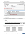
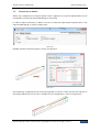
| Data exchange scope.
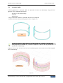
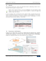
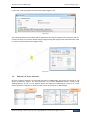
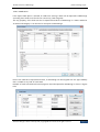
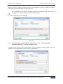
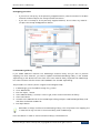
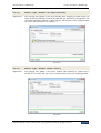
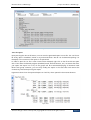
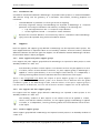
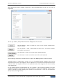
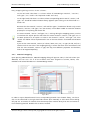
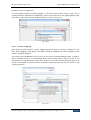
Figure II-28 shows how the model looks like after exporting it to FEM-Design.
Figure II-28
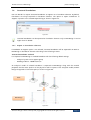
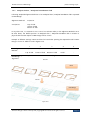
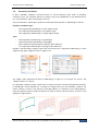
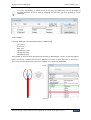
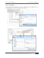
The load value is –1 kN, as defined in Revit. The correct direction of the load is preserved by setting
a positive direction (with the global Z axis) that is consistent with the positive direction of Revit
coordinate system. The load is assigned to a corresponding load case Dead load.
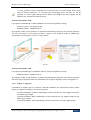
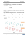
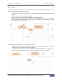
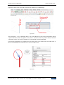
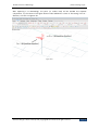
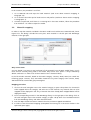
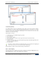
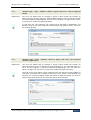
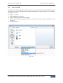
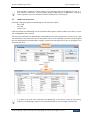
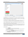
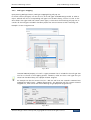
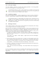
If more force components is assigned into one point load or one surface load, the visible force in
Revit will be displayed as resultant force, as shown in Figure II-29.
Figure II-29
Structural Design Software in Europe AB | Copyright© 2014 StruSoft. All rights reserved.
Page 17