1
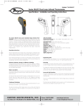
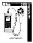
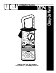
INSTRUCTION MANUAL
1-800-547-5740 • Fax: (503) 643-6322
www.ueitest.com • email: [email protected]
Introduction
Controls and Indicators
The INF215 is perfect for frequent use in advanced or specialty application
environments, where wide temperature ranges and superior optics are
essential for use on targets at greater distances. A UV Worklight has been
added to diversify the INF215’s use. This full-featured IR Thermometer
is the most comprehensive and best-valued Infrared Thermometer on
the market.
6
The INF185’s increased features offer advanced trend analysis for
professionals that require a greater quality of infrared optics, extended
measurement and the versatility of a K-Type surface or contact probe. A
worklight has been added to allow visibility in low-lit workspaces.
1
Features include (INF215)
• -76˚ to 1400˚F
• 30:1 Distance to Spot Ratio
• UV Worklight
5
Features include (INF185)
• -76˚ to 932˚F
• 12:1 Distance to Spot Ratio
• Worklight - Bright white
Shared. . .
• MIN/MAX/Differential, Average
• Adjustable emissivity levels
• Hi/Lo Alarm (User adjustable)
• Contact probe input
• Over-molded handle with comfort grip
• Carry Case
Safety Notes
2
4
Front view
1.
2.
3.
4.
Trigger: Initiates measurements.
IR Sensor
Laser Pointer Beam
Worklight: INF185 = white
INF215 = UV
5. Battery Compartment
6. Thermocouple Socket
Before using this infrared thermometer, read all safety information
carefully. In this manual the word "WARNING" is used to indicate
conditions or actions that may pose physical hazards to the user. The
word "CAUTION" is used to indicate conditions or actions that may
damage this instrument.
NOTE: The INF185/INF215 is not recommended for use on shiny
surfaces such as chrome, mirrors or polished metals.
3
Displays and Indicators
7
6
2
4
3
5
WARNING!
To avoid thermal shock, the instrument should be stored at room
temperature between 32˚ to 122˚F (0˚ to +50˚C).
WARNING!
DO NOT look directly into the laser beam. Permanent eye damage
may result.
INF185/215-MAN
1
1. Mode Push-button
2. Lock and Backlight
( ) Push-button
3. ˚F/˚C and Laser
( ) Push-button
4. Value labeled
parameters
5. Scale
6. Battery level
7. Hi/Lo Alarm
8. Scan indicator
9. Backlight
10. Laser splash
11. HOLD
12. LOCK
13. Polarity
14. MIN, MAX, DIF,
AVG, E, E , PRB
P. 1
Operating Instructions
Taking Measurements
To take a temperature measurement using your INF185/215, you simply
point the aperture at an object (with or without using the laser sighting)
and pull the trigger. The object’s temperature will show up on the
display and update at a rate of approximately 2 times per second.
There will be a delay of approximately one-second between the time
you initially pull the trigger and the time the display comes on. The 60second auto-hold initiates at the moment you release the trigger. The
maximum temperature is viewed beside the “
“ icon.
NOTE: This thermometer will automatically shut off if left idle for more
than 60 seconds, unless in PRB mode. When in PRB mode, instrument
will shut off if left idle for more than 12 minutes.
Follow these general guidelines to ensure you get the most accurate
readings possible:
• Be aware that you cannot measure the temperature of air
between the Infrared thermometer and an object. Air vents
(registers) are quick to take on the temperature of outlet air.
However, you must aim directly at the vent if you are measuring
outlet air temperature.
• Keep your infrared thermometer away from strong electrical
fields. When working near a strong electrical field, like that under
the hood of your car, watch for unusual readings or an "over
load" indication. Often, you can move the thermometer just a few
inches to escape the influence of the interference.
• Keep your INF185/215 within its use and storage temperature
range. Excessive heat or cold will adversely affect the accuracy of
your readings. When the trigger is pulled the target’s temperature
will be displayed in a near real-time mode (less than 1/2 second
between measurements). The temperature will remain on the dis
play for seven seconds after the trigger is released.
Mode and Functions
Press the “MODE” push-button will scroll through the following options:
• Be sure the measured object fills the "spot" seen by the
aperture. The distance to spot ratio for the INF185 is
12:1. The distance to spot ratio for the INF215 is 30:1.
: Emissivitydata. (The default emissivity is 0.95)
This shows the one-foot spot fitting within the one-foot target area. At
this distance, and anything closer, the target’s temperature will be
accurately measured (Fig 1).
NOTE: If the two-foot diameter spot includes unwanted objects in
the background that are not part of the one-foot square target. The
temperature of the background objects will be figured in with the
target’s temperature and throw off your measurement.
(Fig 1)
• When comparing temperatures of similar objects that are far away,
take your measurements at the same distance and angle to the
target each time.
• When looking for abnormally hot or cold targets it may be
acceptable to include background objects so long as the
temperatures in the background and your methods are consistent.
: Press the “MODE” push-button, then press “ “ or “ “
push-buttons to set the emissivity, then press the “MODE”
push-button again to confirm it. The emissivity can be
changed from 0.10 to 1.
: Press the “MODE” push-button for the maximum (MAX),
minimum (MIN), different between MAX and MIN (DIF)
and average (AVG) modes. During the measurement, the
special modes reading will be displayed at the bottom of
the display near the mode icon.
: Press the “ “ or “ “ push-buttons to change the
“High Alarm” (HAL) or “Lo Alarm” (LAL), then press the
trigger to confirm it. For example: when the reading 27˚C <
LAL 27.1˚C, the low “Lo Alarm” icon will flash and you will
hear a beep sound.
: Connect the thermocouple to the thermocouple socket
and apply the probes to the target being measured. The
thermometer will display the temperature automatically
without pressing any buttons. To see the minimum or
m aximum data during the probe measurement, please
hold down the “ “ or “ “ push-buttons.
• Consider the emissivity of the objects you are measuring.
• Prepare a surface for measurement. Infrared thermometers
measure only the outer surface of an object. If emissivity is affecting
the measurement, or you have difficulty putting the object in the
sensors line-of-site, you may need to prepare a surface that’s easy
for the infrared thermometer to read. A piece of masking tape is a
good target and it will rapidly take on the temperature of the object
it is attached to.
INF185/215-MAN
WARNING!
After measurement of high temperature, the probe may be hot for
a while.
P. 2
Additional Features
Perform this first
Press and release
the trigger to activate
display first
Press and release
the trigger to use
these functions
Verify that the meter
is in one of these modes
In MIN, MAX, DIF,
AVG mode
In all modes
Press to activate the following
LOCK - Press the “ “ pushbutton for LOCK mode ON/OFF
- This locks the IR measurement
for up to 60 minutes
SCALE - Press “ “ push-button to
select ˚C or ˚F
BACKL IGHT/WORKL IGHT Press the “ “ push-button
for backlight function ON/OFF
LASER - Press the “ “ pushbutton for laser function ON/OFF
Changing Scales
To change scales between degrees Fahrenheit and degrees Celsius,
press the button on the panel, (marked °F / °C), while the display is
active. Even if the trigger is released and the display is in its 60-second
automatic hold, you can convert the reading between scales. Each time
you press the scale button, the 60-second hold will reset. The INF155
will default to the scale last used the next time it is turned on.
Using the Laser Sight
The INF185/215 is classified as a "Laser Product", and is regulated by
the FDA.
Battery Indicators
The thermometer incorporates visual low battery
indications.
: “Battery OK” measurements
are possible
: “Battery Low” battery needs to be
replaced, measurements are
still possible
: “Battery Exhausted” measurements
are not possible
Maintenance
Periodic Service
WARNING!
Repair and service of this instrument is to be performed by qualified
personnel only.
Cleaning
Pe r i o d i cally clean your instrument’s case using a damp cloth. DO NOT
use abrasive, flammable liquids, cleaning solvents, or strong detergents as
they may damage the finish, impair safety, or affect the reliability of the
s t r u c t u ral components.
WARNING!
Using controls, making adjustments, or performing procedures in any
manner other than that specified herein may result in hazardous
radiation exposure.
Battery Replacement
Always use a fresh replacement battery of the specified size and type.
Immediately remove the old or weak battery from the meter and
dispose of it in accordance with your local disposal regulations. Old or
defective batteries can leak chemicals that corrode electronic circuits.
LCD Error Messages
The thermometer incorporates visual diagnostic messages as follows:
To replace the battery:
: “Hi” or “Lo” is displayed when the temperature being
measured is outside the settings of HAL and LA L .
: “Er2” is displayed when the thermometer is exposed to
rapid changes in the ambient temperature.
1. Slide the battery cover straight down then away from the
INF185/215 (Fig 2).
2. Replace with fresh “AAA” (2x) batteries.
3. Replace cover.
: “Er3” is displayed when the ambient temperature exceeds
the operation range of 32˚ to 122˚F (0˚ to 50˚C). The
thermometer should be allowed plenty of time (minimum
30 minutes) to stabilize to the working/room temperature.
: For all other error messages it is necessary to reset
the thermometer.
To reset the thermometer, turn the instrument off, remove the battery and
wait for a minimum of one minute. Reinsert the battery and turn it on. If the
error message remains please contact UEi service department for
further assistance.
“AAA” (x2)
INF185/215-MAN
(Fig 2)
P. 3
Lens Care
The sensor lens is the most delicate part of the thermometer. The lens
should be kept clean at all times. Care should be taken when cleaning
the lens using only a soft cloth or cotton swab with water or medical
alcohol. Allowing the lens to fully dry before using the thermometer. Do
not submerge any part of the thermometer in liquids.
WARNING!
Under NO circumstance should you expose batteries to extreme heat or
fire as they may explode and cause injury.
NOTE: This instrument contains no user serviceable parts. If service
becomes necessary, call UEi and ask for the service department. See
the warranty section of this manual for additional details.
Specifications
INF185
Item
Measurement range
Operating range
Accuracy
(Tobj=-59˚-95˚F,
Tamb=77˚C)
(Tobj=-27˚-932˚F,
Tamb=73˚±3˚C)
Resolution
(-9.9-199.9˚F)
Response time (90%)
Distance: Spot
Battery life
Dimensions
Weight
Non-contact Infrared Scan Thermocouple Probe Scan
-76˚ to 932˚F
-83.2˚ to +1999˚F
(-60˚ to +500˚C)
(-64˚ to 1 400˚C)
32˚ to 122˚F (0˚ to +50˚C)
±1.8˚F (1.0˚C)
±2% of reading or 4˚F
(2˚C) whichever is greater
±1% of reading or 1.8˚F
(1.0˚C) whichever is
greater (Test under
Tamb=73±6˚F)
0.10˚F / 0.1˚C
1 second
12 : 1
Standard “AAA” (x2), 140 hours
6.9” x 1.5” x 2.8” (175.2 x 39.0 x 71.9mm)
179 grams
EMC/RFI
Readings may be affected if the unit is operated within radio frequency
electromagnetic field strength of approximately 3 volts per meter, but
the performance of the instrument will not be permanently affected.
IR Thermometers
Infrared Thermometers measure the amount of thermal radiation emitted
from an objects surface. To take a measurement, the object must be
within the field of view of the infrared thermometer, or the reading may
include objects surrounding your target. This target size is determined in
the distance to spot ratio stated on the instruments specifications. At a
ratio of 9:1, a distance from your target of nine feet will give you a circle
with one foot diameter. At 20:1 ratio gives the same one foot target
now at 20 feet, so you can see that higher is better, but ty p i cally more
expensive due to the cost of the optics involved.
The other common question is regarding emissivity. In simple terms
e m i s s i v i tyis a percentage of energy emitted from a surface compared to
the energy emitted from a black body source. If a surface emits one half
(1/2 or 0.5) the amount of energy at a given temperature and wavelengt h
as a black body, it is said to have an emissivity of 0.5.
Surfaces closest to the black body level would be flat black, and those
farthest from it would be mirror or chrome surfaces. With a set emissivity
level some surfaces may measure lower than actual, because their surface
is emitting less thermal radiation at a given temperature. Although you
may have a fixed emissivity of 0.95, most items measured will provide a
reasonably accurate result. Having a fully adjustable emissivity will give
you the ability to fine tune your instrument to a specific application.
To determine the emissivity of the surface being tested, paint a portion
with flat black paint, and then measure the temperature of the painted
area and compare it to the temperature of the standard surface. Use
the following to determine the emissivity to use.
Te m p e rature (Standard area) divided by temperature (painted area). As
an example 61° in the standard area and 68° painted is 61/68 or 0.89
INF215
Item
Measurement range
Operating range
Accuracy
(Tobj=-59˚-95˚F,
Tamb=77˚C)
(Tobj=-27˚-1400˚F,
Tamb=73˚±3˚C)
Resolution
(-9.9-199.9˚F)
Response time (90%)
Distance: Spot
Battery life
Dimensions
Weight
Non-contact Infrared Scan Thermocouple Probe Scan
-76˚ to 1400˚F
-83.2˚ to +1999˚F
(-60˚ to +760˚C)
(-64˚ to 1400˚C)
32˚ to 122˚F (0˚ to +50˚C)
±1.8˚F (1.0˚C)
±2% of reading or 4˚F
(2˚C) whichever is greater
±1% of reading or 1.8˚F
(1.0˚C) whichever is
greater (Test under
Tamb=73±6˚F)
0.10˚F / 0.1˚C
1 second
30 : 1
Standard “AAA” (x2)1.5V, 140 hours
6.9” x 1.5” x 2.8” (175.2 x 39.0 x 71.9mm)
179 grams
NOTE: Under the electromagnetic field of 2V/m from 200 to 600 MHz,
the maximum error is 18˚F (10˚C).
INF185/215-MAN
P. 4
INF185/215
Infrared Thermometer
Limited Warranty
The INF 185/215 is warranted to be free from defects in materials and workmanship for
a period of three years from the date of purchase. If within the warra n ty period your
instrument should become inoperative from such defects, the unit will be repaired or
replaced at UEi’s option. This warra n ty covers normal use and does not cover damage which
occurs in shipment or failure which results from alteration, tampering, accident, misuse,
abuse, neglect or improper maintenance. Batteries and consequential damage resulting from
failed batteries are not covered by warra n ty.
Any implied warranties, including but not limited to implied warranties of merchantability
and fitness for a particular purpose, are limited to the express warranty. UEi shall not
be liable for loss of use of the instrument or other incidental or consequential damages,
expenses, or economic loss, or for any claim or claims for such damage, expenses or
economic loss. A purchase receipt or other proof of original purchase date will be required
before warra n ty repairs will be rendered. Instruments out of warra n ty will be repaired
(when repairable) for a service charge. Return the unit postage paid and insured to:
1-800-547-5740 • FAX: (503) 643-6322
www.ueitest.com • Email: [email protected]
This warranty gives you specific legal rights. You may also have other rights which vary from
state to state.
PLEASE
RECYCLE
Copyright © 2007 UEi
INF185/215-MAN 1/07