1
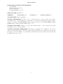
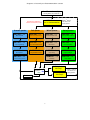
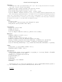
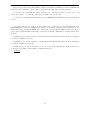
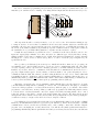
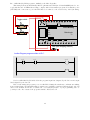
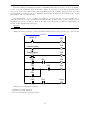
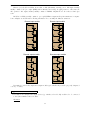
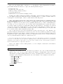
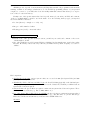
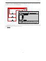
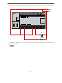
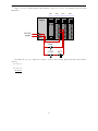
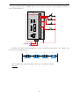
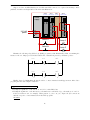
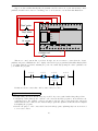
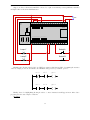
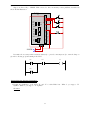
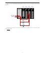
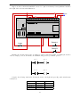
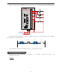
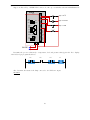
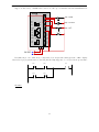
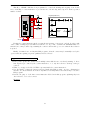
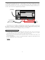
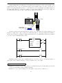
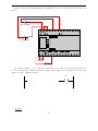
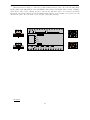
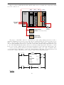
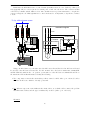
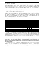
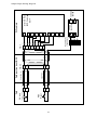
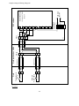
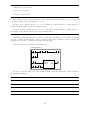
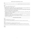
This example shows a Koyo “CLICK” PLC (model C0-02DD1-D) wired to two toggle switches and one
LED indicator lamp, complete with a demonstration program:
C0-02DD1-D
CLICK
Koyo
C1
X1
X2
X3
X4
PWR
RUN
ERR
RUN
C2
STOP
Y1
LED (with dropping resistor)
Y2
Y3
PORT 1
TX1
Y4
RX1
+V
AD1V
TX2
AD1I
RX2
AD2V
PORT 2
AD2I
Toggle switch
ACOM
PORT 3 RS-485
DA1V
DA1I
TX3
RX3
DA2V
LG
0
DA2I
24V
24 VDC
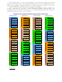
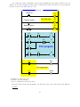
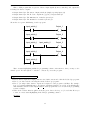
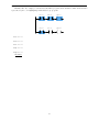
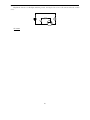
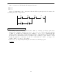
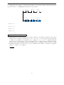
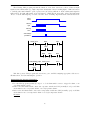
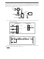
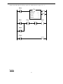
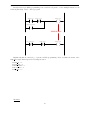
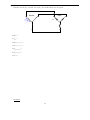
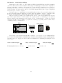
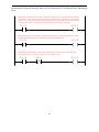
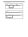
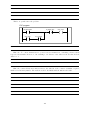
Ladder-Diagram program written to PLC:
X1
X2
X2
X1
Y1
END
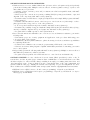
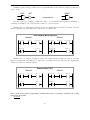
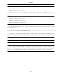
Note how Koyo I/O is labeled in the program: input bits designated by the letter X and output bits
designated by the letter Y.
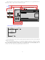
Based on the wiring and program you see for this PLC, identify the switch state combinations resulting
in an energized lamp. Try duplicating this program in your own PLC (even if it is a different brand or model)
and see how it functions. Be sure to activate the color highlighting feature of your programming editor so
you may see the “live” status of the program’s virtual contacts and coil!
file i04513
26