1
Rabbit® RIO™
User’s Manual
019–0158
• 080930–E
Rabbit RIO User’s Manual
Part Number 019-0158 • 080930–E • Printed in U.S.A.
©2006–2008 Digi International Inc. • All rights reserved.
No part of the contents of this manual may be reproduced or transmitted in any form or by any means
without the express written permission of Digi International.
Permission is granted to make one or more copies as long as the copyright page contained therein is
included. These copies of the manuals may not be let or sold for any reason without the express written
permission of Digi International.
Digi International reserves the right to make changes and
improvements to its products without providing notice.
Trademarks
Rabbit and Dynamic C are registered trademarks of Digi International Inc.
Rabbit RIO is a trademark of Digi International Inc.
The latest revision of this manual is available on the Rabbit Web site, www.rabbit.com,
for free, unregistered download.
Digi International Inc.
www.rabbit.com
Rabbit RIO User’s Manual
TABLE OF CONTENTS
Chapter 1. The Rabbit RIO
1
1.1 Overview...............................................................................................................................................1
1.2 Key Features .........................................................................................................................................2
1.3 Development and Evaluation Tools......................................................................................................2
1.4 Block Diagram of Rabbit RIO I/O Blocks............................................................................................3
1.5 Pin Functions and Descriptions ............................................................................................................4
1.6 Pinouts ..................................................................................................................................................5
1.7 Mechanical Dimensions and Land Pattern — TQFP Package ...........................................................10
1.8 DC Characteristics ..............................................................................................................................12
1.9 AC Characteristics ..............................................................................................................................13
1.10 Memory Access Times .....................................................................................................................13
1.10.1 Parallel Mode ...........................................................................................................................13
1.10.2 SPI/RabbitNet Mode ................................................................................................................15
Chapter 2. Master-Level Features
17
2.1 Overview.............................................................................................................................................17
2.2 Block Diagram ....................................................................................................................................18
2.3 Clocks .................................................................................................................................................19
2.4 Reset....................................................................................................................................................19
2.5 Bus Interface .......................................................................................................................................19
2.5.1 Parallel Mode .............................................................................................................................20
2.5.2 Serial Mode — Clocked Serial Interface ...................................................................................23
2.5.3 Serial Mode — RabbitNet Device Interface ..............................................................................26
2.5.4 Serial Mode — RabbitNet Hub Interface ..................................................................................27
2.6 Synchronization ..................................................................................................................................28
2.7 Interrupts .............................................................................................................................................29
2.8 Registers..............................................................................................................................................29
2.9 Register Descriptions ..........................................................................................................................31
2.9.1 Master Control Register .............................................................................................................31
2.9.2 Master Status Register ...............................................................................................................32
2.9.3 Master Prescale Register ............................................................................................................32
2.9.4 Master Alternate Data Register ..................................................................................................33
2.9.5 Master Protection Command Register .......................................................................................34
2.9.6 Master Protection Prescale Register ..........................................................................................35
2.9.7 Watchdog Timer Registers .........................................................................................................35
2.9.8 Pointer Registers ........................................................................................................................36
2.9.9 Indirect Registers .......................................................................................................................36
Table of Contents
Chapter 3. Block-Level Features
37
3.1 Overview ............................................................................................................................................ 37
3.1.1 Simplified Block Diagram ......................................................................................................... 38
3.2 Internal Block Registers ..................................................................................................................... 39
3.3 Block Control ..................................................................................................................................... 40
3.4 Register Descriptions ......................................................................................................................... 41
3.4.1 Pointer and Indirect Registers ................................................................................................... 41
3.4.2 Command Register .................................................................................................................... 42
3.4.3 Mode Register ........................................................................................................................... 43
3.4.4 Interrupt Enable and Status Registers ........................................................................................ 44
3.4.5 Counter Toggle Register ............................................................................................................ 46
3.4.6 Synch Control Register .............................................................................................................. 47
3.4.7 Increment/In-Phase/Begin Control Register .............................................................................. 48
3.4.8 Decrement/Quadrature/End Control Register ........................................................................... 49
3.4.9 Status Control Registers ............................................................................................................ 50
3.4.10 Pin Control Registers ............................................................................................................... 51
3.4.11 Match Registers ....................................................................................................................... 51
3.4.12 Count Limit Registers .............................................................................................................. 52
3.4.13 Count Begin Registers ............................................................................................................. 52
3.4.14 Count End Registers ................................................................................................................ 52
3.4.15 Count Value Registers ............................................................................................................. 53
Chapter 4. General-Purpose I/O
55
4.1 Overview ............................................................................................................................................ 55
4.1.1 Block Diagram ........................................................................................................................... 55
4.2 Dependencies ..................................................................................................................................... 55
4.3 Operation ............................................................................................................................................ 56
4.3.1 Setup .......................................................................................................................................... 56
4.3.2 Example of Operation ................................................................................................................ 56
4.3.3 Pattern Mode ............................................................................................................................. 56
4.4 Register Descriptions ......................................................................................................................... 57
Chapter 5. Pulse-Width Modulator
59
5.1 Overview ............................................................................................................................................ 59
5.1.1 Block Diagram ........................................................................................................................... 59
5.2 Dependencies ..................................................................................................................................... 60
5.3 Operation ............................................................................................................................................ 60
5.3.1 Setup .......................................................................................................................................... 60
5.3.2 Example ..................................................................................................................................... 61
5.4 Other Comments ................................................................................................................................ 62
5.4.1 General-Purpose I/O .................................................................................................................. 62
5.4.2 External Synchronization .......................................................................................................... 62
5.4.3 Interrupts .................................................................................................................................... 62
5.4.4 Higher Drive Current Operations .............................................................................................. 62
Chapter 6. Variable-Phase Pulse-Width Modulator
63
6.1 Overview ............................................................................................................................................ 63
6.1.1 Block Diagram ........................................................................................................................... 63
6.2 Dependencies ..................................................................................................................................... 64
6.3 Operation ............................................................................................................................................ 65
6.3.1 Setup .......................................................................................................................................... 65
6.3.2 Example of Operation ................................................................................................................ 66
6.4 Other Comments ................................................................................................................................ 67
Rabbit RIO User’s Manual
Chapter 7. Input Capture
69
7.1 Overview.............................................................................................................................................69
7.1.1 Block Diagram ...........................................................................................................................69
7.2 Dependencies ......................................................................................................................................70
7.3 Operation ............................................................................................................................................70
7.3.1 Setup ...........................................................................................................................................70
7.3.2 Example .....................................................................................................................................71
7.4 Other Comments .................................................................................................................................72
7.4.1 General-Purpose I/O ..................................................................................................................72
7.4.2 Interrupts ....................................................................................................................................72
Chapter 8. Quadrature Decoder
73
8.1 Overview.............................................................................................................................................73
8.1.1 Block Diagram ...........................................................................................................................73
8.2 Dependencies ......................................................................................................................................74
8.3 Operation ............................................................................................................................................74
8.3.1 Setup ...........................................................................................................................................75
8.3.2 Example .....................................................................................................................................75
8.4 Other Comments .................................................................................................................................76
8.4.1 General-Purpose I/O ..................................................................................................................76
8.4.2 External Synchronization ...........................................................................................................76
8.4.3 Interrupts ....................................................................................................................................76
Chapter 9. RabbitNet Hub
77
9.1 Overview.............................................................................................................................................77
9.2 Hub Functions.....................................................................................................................................77
9.3 Hub Commands ..................................................................................................................................77
9.4 Reset and Enumeration .......................................................................................................................79
9.5 Additional RabbitNet Information......................................................................................................79
9.6 Registers..............................................................................................................................................80
9.6.1 RabbitNet Status Register ..........................................................................................................81
9.6.2 RabbitNet Parameter Register ....................................................................................................81
9.6.3 RabbitNet ID Register ................................................................................................................81
9.6.4 RabbitNet Reset Status Register ................................................................................................82
Index
Table of Contents
83
Rabbit RIO User’s Manual
1. THE RABBIT RIO
1.1 Overview
The Rabbit RIO is a peripheral device designed to be incorporated into systems requiring
versatile timing controls and a broader range of functionality. The Rabbit RIO can be used
with any microprocessor.
The Rabbit RIO communicates with the microprocessor in either a parallel or a serial
mode. The particular communication mode is determined during power-up. In the parallel
mode, the chip communicates with the microprocessor through a parallel bus with eight
data bits, five address bits, and four control bits. The serial mode can be used for bidirectional data flow on one wire or via the SPI and RabbitNet protocols. In the serial mode, the
parallel data lines are available to be used as general-purpose I/O. The multiple communication modes allow the Rabbit RIO to be a part of a wide variety of systems that use any
one of these communication methods.
Implementing the Rabbit RIO as a RabbitNet hub provides a simple, efficient, and flexible
means of establishing a network of RabbitNet peripheral cards. The RabbitNet architecture allows a hub to connect to seven peripheral cards, and support for two levels of hubs
allows a master device to control up to 49 RabbitNet peripheral cards.
The design of the Rabbit RIO’s I/O blocks allows any of the eight identical I/O blocks, each
with four bits or I/O pins, to be programmed to perform any number of different functions,
including a pulse-width modulator, a pulse-position modulator, event counters, quadrature
decoders, pulse measurements, and I/O, including pin-pair protection for applications such
as H-bridge drivers.
The main clock can be used directly by each I/O block, or it may be prescaled down to a
lower frequency. Either clock source can be used by the 16-bit counter, which is the core
of each I/O block. This counter is complemented by a number of registers that provide
access and control to the counter for the various Rabbit RIO functions that it involves.
The Rabbit RIO can be incorporated without any glue logic in a Rabbit-based system,
enabling a more efficient use of resources. Rabbit’s Dynamic C software allows for seamless integration of hardware and software. Dynamic C provides a complete set of function
calls to enable you to use the Rabbit RIO without having to write any additional drivers.
The Rabbit RIO can operate at clock speeds up to 40 MHz. It is powered by 3.3 V, but the
I/O are 5 V tolerant. The Rabbit RIO is packaged in a 64-pin 10 mm ×10mm TQFP,
making its small footprint and low profile ideal for embedded applications.
Chapter 1 The Rabbit RIO
1
1.2 Key Features
• 5 V tolerant
• Clock speed up to 40 MHz
• 64-pin 10 mm ×10 mm TQFP package
• Multiple communication interfaces — SPI, parallel, and RabbitNet
• 8 independent functional I/O blocks with 4 pins each
• Any pin on each I/O block is capable of:
X Generating PWM outputs and variable-phase PWM outputs
X Pulse count
X Input capture (pulse length or frequency)
X Decoding quadrature signals
X Provide extended I/O pins to the microprocessor
X Pin-pair protection for driving H bridges
• Up to 32 digital I/O lines, up to 4 general-purpose inputs
• Global or block synch input to coordinate outputs
• Interrupt request pin
• RoHS compliant
• High-performance 8-bit device requires no glue logic to Rabbit systems
• RabbitNet hub feature allows control of up to seven RabbitNet devices in each of two
levels for a total of up to 49 RabbitNet devices
• Functionality well-suited for machine control
• Dynamic C libraries allow for Rabbit RIO to be up and running in no time
• Small footprint and multiple functions allow for versatile system
1.3 Development and Evaluation Tools
Rabbit also has an application kit featuring the Rabbit RIO to provide the harware and
software tools to help you use the Rabbit RIO for I/O expansion.
• RIO Programmable I/O Kit [Part No. 101-1147 (North American markets) and Part No.
101-1148 (overseas markets)]—comes with two CD-ROMs that includes Dynamic C
10.11 or a later version, an RCM4110 RabbitCore module, and a RIO Prototyping
Board. The software bundle on the supplemental CD provides the Dynamic C function
calls and sample programs that illustrate the use of the Rabbit RIO chip included on the
RIO Prototyping Board and can serve as a template for you to develop your own
application.
2
Rabbit RIO User’s Manual
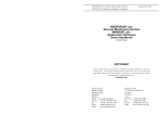
1.4 Block Diagram of Rabbit RIO I/O Blocks
DECREMENT
INCREMENT
BORROW LSB
CARRY MSB
MATCH 3
MATCH 2
MATCH 1
MATCH 0
M0MR
CBMR
CEMR
CVMR
CBLR
CELR
CVLR
M0LR
IER
INCREMENT
LOGIC &
LEVEL
CONTROLLER
INC
DECREMENT
LOGIC &
LEVEL
CONTROLLER
DEC
M1MR
COUNTER
M1LR
ICR
M2MR
M2LR
DCR
BORROW
LSB
M3MR
CARRY
MSB
CLKI
MPR
M3LR
FNC RST
CVMR
P0
MR
CVLR
P0CR
STAT0
SET/RST
P1
RESET
LOGIC
S0CR
P1CR
STAT1
SET/RST
SYNC
CONTROL
&
LEVEL
CONTROL
P2
P2CR
S1CR
STAT2
SET/RST
P3
SCR
CR
S2CR
P3CR
STAT3
SET/RST
CTR
S3CR
GSYNC
Chapter 1 The Rabbit RIO
3
1.5 Pin Functions and Descriptions
Pin Group
Hardware
Pin Name
Direction
Function
/RESET
Input
Master Reset
CLK
Input
Clock In
BLOCK[2:1] or GPIN[2:1]
BLOCK[0]
G//B
/P/I
Input
Address Bus or GPI*
D7/SERCLK
D6/SERI
D5/BL6Pin[3]
D4/BL6Pin[2]
D3/BL6Pin[1]
D2/BL7Pin[3]
D1/BL7Pin[2]
D0/BL7Pin[1]
Bidirectional
Parallel Data Bus or
Serial Control Bus &
I/O Block Pins
/CS
Input
I/O Chip Select
/IORD or GPIN[4]
Input
I/O Read Enable or GPI*
/IOWR or GPIN[3]
Input
I/O Write Enable or GPI*
/INT
Output
Interrupt Request
/WAIT/SERO
Output
Wait Request or
Serial Out
SER//PAR
Input
Serial/Parallel Bus Select
Shared
GSYNC
Input
Global Sync
I/O Pins
BL0Pin[3:0] –
BL5Pin[3:0] &
BL6Pin[0] &
BL7Pin[0]
Input/Output
I/O Block Pins
Power
VDDINT
VDDIO
Power
Internal Power
I/O Power
Ground
VSSINT
VSSIO
Ground
Internal Ground
I/O Ground
CPU Buses
Status &
Control
* The GPI options are general-purpose inputs when operating in a serial mode.
4
Rabbit RIO User’s Manual
49
50
51
52
53
54
55
56
57
58
59
60
61
BL4Pin[2]
BL4Pin[1]
62
1
63
VDDIO
64
VSSIO
BL4Pin[3]
BL5Pin[0]
BL5Pin[1]
BL5Pin[2]
BL5Pin[3]
BL6Pin[0]
BL7Pin[0]
VDDIO
GSYNC
CLK
/RESET
SER//PAR
G//B
BLOCK[2]
VSSIO
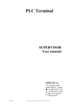
1.6 Pinouts
D6
VSSIO
8
41
VSSIO
BL3Pin[1]
BL3Pin[0]
BL2Pin[3]
9
40
10
39
11
38
D5
D4
D3
VSSINT
BL2Pin[2]
BL2Pin[1]
12
37
13
36
14
35
VDDINT
D2
D1
BL2Pin[0]
15
34
D0
VDDIO
16
33
VDDIO
VSSIO
BL1Pin[3]
BL1Pin[2]
BL1Pin[1]
BL1Pin[0]
BL0Pin[3]
BL0Pin[2]
VDDIO
BL0Pin[1]
BL0Pin[0]
/IORD
/IOWR
/CS
/WAIT
/INT
VSSIO
32
42
31
7
30
43
29
6
VSSINT
D7
28
44
27
5
26
/P/I
VDDINT
BL3Pin[3]
BL3Pin[2]
25
45
24
4
23
BL4Pin[0]
22
BLOCK[1]
BLOCK[0]
21
46
20
3
19
47
18
VDDIO
2
17
48
Figure 1-1. Parallel Pinout
Chapter 1 The Rabbit RIO
5
49
50
51
52
53
54
55
56
57
58
59
60
61
62
VSSIO
BL4Pin[3]
BL5Pin[0]
BL5Pin[1]
BL5Pin[2]
BL5Pin[3]
BL6Pin[0]
BL7Pin[0]
VDDIO
GSYNC
CLK
/RESET
SER//PAR
G//B
GPIN[2]
VSSIO
63
64
1
48
12
37
13
36
14
35
15
34
16
33
VDDIO
GPIN[1]
BLOCK[0]
/P/I
VSSINT
SERCLK
SERI or SERIO
VSSIO
BL6Pin[3]
BL6Pin[2]
BL6Pin[1]
VDDINT
BL7Pin[3]
BL7Pin[2]
BL7Pin[1]
VDDIO
VSSIO
BL1Pin[3]
BL1Pin[2]
BL1Pin[1]
BL1Pin[0]
BL0Pin[3]
BL0Pin[2]
VDDIO
BL0Pin[1]
BL0Pin[0]
GPIN[4]
GPIN[3]
/CS
SERO
/INT
VSSIO
32
38
31
39
11
30
10
29
40
28
9
27
41
26
42
8
25
7
24
43
23
44
6
22
45
5
21
4
20
46
19
47
3
18
2
17
VDDIO
BL4Pin[2]
BL4Pin[1]
BL4Pin[0]
VDDINT
BL3Pin[3]
BL3Pin[2]
VSSIO
BL3Pin[1]
BL3Pin[0]
BL2Pin[3]
VSSINT
BL2Pin[2]
BL2Pin[1]
BL2Pin[0]
VDDIO
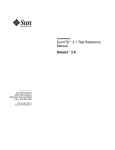
Figure 1-2. Serial Pinout — SPI Interface Mode
6
Rabbit RIO User’s Manual
49
50
51
52
53
54
55
56
57
58
59
60
61
BL5Pin[0]
BL5Pin[1]
BL5Pin[2]
BL5Pin[3]
BL6Pin[0]
BL7Pin[0]
VDDIO
GSYNC
CLK
/RESET
SER//PAR
G//B
GPIN[2]
VSSIO
62
63
BL4Pin[2]
VSSIO
BL4Pin[3]
1
64
VDDIO
42
8
41
9
40
10
39
11
38
12
37
13
36
14
35
15
34
16
33
SERCLK
MOSI
VSSIO
BL6Pin[3]
BL6Pin[2]
BL6Pin[1]
VDDINT
BL7Pin[3]
BL7Pin[2]
BL7Pin[1]
VDDIO
BL1Pin[2]
BL1Pin[1]
BL1Pin[0]
BL0Pin[3]
BL0Pin[2]
VDDIO
BL0Pin[1]
BL0Pin[0]
GPIN[4]
GPIN[3]
/CS
MISO
/INT
VSSIO
VSSIO
BL1Pin[3]
32
43
7
31
BL3Pin[3]
BL3Pin[2]
VSSIO
BL3Pin[1]
BL3Pin[0]
BL2Pin[3]
VSSINT
BL2Pin[2]
BL2Pin[1]
BL2Pin[0]
VDDIO
30
VSSINT
29
44
6
28
5
27
45
26
4
25
BL4Pin[0]
VDDINT
GPIN[0]
/P/I
24
46
23
3
22
BL4Pin[1]
21
GPIN[1]
20
47
19
2
18
VDDIO
17
48
Figure 1-3. Serial Pinout — RabbitNet Device Interface Mode
Chapter 1 The Rabbit RIO
7
49
50
51
52
53
54
55
56
57
58
MISO5
/CS5
SERCLK6
BL7Pin[0]
VDDIO
GSYNC
CLK
/RESET
SER//PAR
G//B
GPIN[2]
VSSIO
59
60
61
62
63
MISO4
VSSIO
/CS4
SERCLK5
MOSI5
1
64
VDDIO
42
8
41
9
40
10
39
11
38
12
37
13
36
14
35
15
34
16
33
SERCLK
MOSI
VSSIO
/CS6
MISO6
MOSI6
VDDINT
BL7Pin[3]
BL7Pin[2]
BL7Pin[1]
VDDIO
SERCLK1
/CS0
MISO0
VDDIO
MOSI0
SERCLK0
GPIN[4]
GPIN[3]
/CS
MISO
/INT
VSSIO
VSSIO
/CS1
MISO1
MOSI1
32
43
7
31
/CS3
MISO3
VSSIO
MOSI3
SERCLK3
/CS2
VSSINT
MISO2
MOSI2
SERCLK2
VDDIO
30
44
6
29
5
/P/I
VSSINT
28
45
27
4
26
SERCLK4
VDDINT
25
GPIN[0]
24
46
23
3
22
MOSI4
21
GPIN[1]
20
47
19
2
18
VDDIO
17
48
Figure 1-4. Serial Pinout — RabbitNet Hub Interface Mode
8
Rabbit RIO User’s Manual
49
50
51
52
53
54
55
56
57
58
59
60
61
62
BL4Pin[2]
BL4Pin[1]
63
VSSIO
BL4Pin[3]
BL5Pin[0]
BL5Pin[1]
BL5Pin[2]
BL5Pin[3]
BL6Pin[0]
BL7Pin[0]
VDDIO
GSYNC
CLK
/RESET
SER//PAR
G//B
BLOCK[2]
VSSIO
1
64
VDDIO
48
VDDIO
2
47
3
46
BLOCK[1]
BLOCK[0]
BL4Pin[0]
VDDINT
4
45
5
44
BL3Pin[3]
BL3Pin[2]
6
43
7
42
VSSIO
BL3Pin[1]
8
BL3Pin[0]
BL2Pin[3]
10
11
38
VSSINT
BL2Pin[2]
12
37
13
36
BL2Pin[1]
BL2Pin[0]
14
35
15
34
D1/BL7Pin[2]
D0/BL7Pin[1]
VDDIO
16
33
VDDIO
40
32
31
30
39
29
28
27
26
25
24
23
22
20
19
18
17
41
D7/SERCLK
D6/SERI
VSSIO
D5/BL6Pin[3]
D4/BL6Pin[2]
D3/BL6Pin[1]
VDDINT
D2/BL7Pin[3]
VSSIO
BL1Pin[3]
BL1Pin[2]
BL1Pin[1]
BL1Pin[0]
BL0Pin[3]
BL0Pin[2]
VDDIO
BL0Pin[1]
BL0Pin[0]
/IORD
/IOWR
/CS
/WAIT /SERO
/INT
VSSIO
21
Core powered from
VDDINT and VSSINT
9
/P/I
VSSINT
Figure 1-5. General Pinout
Chapter 1 The Rabbit RIO
9
1.7 Mechanical Dimensions and Land Pattern — TQFP Package
12.0 ± 0.2 mm
10.00 ± 0.10 mm
48
16
33
10.00 ± 0.10 mm
1
12.0 ± 0.2 mm
49
64
32
17
0.22 ± 0.05 mm
0.50 mm
1.40 ± 0.05 mm
0.125 typ.
The same pin dimensions apply
along the x axis and the y axis.
0.60 ± 0.15
1.00 mm
Figure 1-6. Mechanical Dimensions Rabbit RIO TQFP Package
10
Rabbit RIO User’s Manual
Figure 1-7 shows the PC board land pattern for the Rabbit RIO in a 64-pin TQFP package.
This land pattern is based on the IPC-SM-782 standard developed by the Surface Mount
Land Patterns Committee and specified in Surface Mount Design and Land Pattern Standard, IPC, Northbrook, IL, 1999.
14.2 mm (max.)
0.50 mm
14.2 mm (max.)
10.4 mm (min.)
7.5 mm
12.3 mm
10.4 mm (min.)
0.254 mm (max.)
1.9 mm
7.5 mm
12.3 mm
TOLERANCE AND SOLDER JOINT ANALYSIS
JT: 0.290.55 mm
JH: 0.290.604 mm
Lmin
T
J:
L:
S:
T:
W:
Smax
Gmin: 10.4 mm
Zmax: 14.2 mm
Toe Fillet
JS: -0.010.077 mm
Heel Fillet
Wmin
X: 0.254 mm
(max.)
Side Fillet
Solder fillet min/max (toe, heel, and side respectively)
Toe-to-toe distance across chip
Heel-to-heel distance across chip
Toe-to-heel distance on pin
Width of pin
Figure 1-7. PC Board Land Pattern for Rabbit RIO 64-pin TQFP
Chapter 1 The Rabbit RIO
11
1.8 DC Characteristics
Table 1-1. Preliminary DC Electrical Characteristics
Parameter
Operating Temperature
Storage Temperature
Core Supply Voltage
Symbol
TA
VDDCORE
Min
Core
Core current @ 7.3728 MHz, 25°C
85°C
-55°C
125°C
3.0 V
I/O Ring Current @ 22.1184 MHz, 25°C
11.0 mA
5.5 mA
VDDIO
IIO
IIO
I/O Ring
3.3 V
3.6 V
1.1 mA
0.9 mA
0.9 mA
Input Low Voltage (VDDIO = 3.3 V)
VIL
0.8 V
Input High Voltage (VDDIO = 3.3 V)
VIH
2.0 V
Output Low Voltage (VDDIO = 3.3 V)
VOL
0.4 V
Output High Voltage (VDDIO = 3.3 V)
VOH
2.4 V
Maximum I/O Input Voltage
12
3.0 V
1.0 mA
I/O Ring Current @ 3.6864 MHz, 25°C
Output Drive
3.6 V
16.3 mA
ICORE
I/O Ring Current @ 11.0592 MHz, 25°C
I/O Ring Current @ 7.3728 MHz, 25°C
3.3 V
31.3 mA
Core current @ 3.6864 MHz, 25°C
I/O Ring Supply Voltage
Max
-40°C
Core Current @ 22.1184 MHz, 25°C
Core current @ 11.0592 MHz, 25°C
Typ
3.3 V
IDRIVE
5.0 V
8 mA
Rabbit RIO User’s Manual
1.9 AC Characteristics
Table 1-2. Preliminary AC Electrical Characteristics
Parameter
Symbol
Min
Typ
fmain
Clock Frequency
Max
40 MHz
1.10 Memory Access Times
All access time measurements are taken at 50% of the signal height.
1.10.1 Parallel Mode
Table 1-3. Parallel Bus Read Time Delays
(VDD = 3.3 V ± 10%, TA = -40°C to 85°C)
Parameter
Symbol
Min
Typ
Max
Tadr
6 ns
Clock to Chip Select Delay
TIOCS
6 ns
Clock to Output Enable Delay
TIORD
6 ns
Data Setup Time
Tsetup
1 ns
Data Hold Time
Thold
0 ns
Clock to Address Delay
Table 1-4. Parallel Bus Write Time Delays
(VDD = 3.3 V ± 10%, TA = -40°C to 85°C)
Parameter
Symbol
Min
Typ
Max
Tadr
6 ns
Clock to Chip Select Delay
TIOCS
6 ns
Clock to Write Strobe Delay
TIOWR
6 ns
High Z to Data Valid Relative to Clock
TDHZV
10 ns
Data Valid to High Z Relative to Clock
TDVHZ
10 ns
Clock to Address Delay
Chapter 1 The Rabbit RIO
13
Memory Read
T2
T1
CLK
ADDR
valid
Tadr
/IOCS
/IORD
TIOCS
TIOCS
TIORD
D[7:0]
TIORD
Tsetup
valid
Thold
Memory Write
T1
T2
CLK
ADDR
/IOCS
/IOWR
D[7:0]
valid
Tadr
TIOCS
TIOCS
TIOWR
TIOWR
valid
TDHZV
TDVHZ
Figure 1-8. Memory Read and Write Cycles
14
Rabbit RIO User’s Manual
1.10.2 SPI/RabbitNet Mode
Table 1-5. SPI/RabbitNet Bus Access Time Delays
(VDD = 3.3 V ± 10%, TA = -40°C to 85°C)
Parameter
Symbol
Min
Serial Clock Period
TCP
25 ns
Serial Clock Pulse Width High
TCH
12 ns
Serial Clock Pulse Width Low
TCL
12 ns
Chip Select Fall to Input Data Valid
TCSD
0 ns
Chip Select Leading Time Before First
Clock Edge
TL
25 ns
Chip Select Trailing Timer After Last
Clode Edge
TT
25 ns
Input Data Setup Time
TDS
12 ns
Input/Output Data Hold Time
TDH
12 ns
Chip Select Pulse High
TCSW
100 ns
/IOCS
Typ
Max
TCSW
TL
TCL
SERCLK
TDS
TCSD
TCH
TT
TCP
SERI
TDH
SERO
Figure 1-9. SPI/RabbitNet Bus Access Time Delays
Chapter 1 The Rabbit RIO
15
16
Rabbit RIO User’s Manual
2. MASTER-LEVEL FEATURES
2.1 Overview
The Rabbit RIO uses master-level registers to access individual I/O blocks or to control
their overall function. Unlike block registers, master registers can be accessed directly
through the five-bit address and eight-bit data bus. In the parallel communication mode,
these two buses are accessed through address and data bus pins. In the serial communication mode, the data and address must be decoded from the serial bit stream. Changing the
communication mode is a simple matter of pulling the G//B, /P/I, BLOCK[0], and
SER//PAR pins high or low.
Chapter 2 Master-Level Features
17
2.2 Block Diagram
D2/BL7Pin3
D1/BL7Pin2
D0/BL7Pin1
Global Control
CLOCK
BUS
SYNC
RESET
/RESET
CLK
BLOCK[2:0]
G/C
P/I
/CS
/IORD
/IOWR
/INT
/WAIT /SERO
SER/PAR
GSYNC
BUS INTERFACE
Rabbit RIO Chip Master-Level Features
BLOCK 0
BLOCK 6
BLOCK 1
BL1Pin0
BL1Pin1
BL1Pin2
BL1Pin3
D7/SERCLK
D6/SERI
D5/BL6Pin3
D4/BL6Pin2
D3/BL6Pin1
BL6Pin0
BL7Pin0
18
BL0Pin0
BL0Pin1
BL0Pin2
BL0Pin3
BLOCK 7
BL5Pin0
BL5Pin1
BL5Pin2
BL5Pin3
BLOCK 5
BLOCK 2
BL2Pin0
BL2Pin1
BL2Pin2
BL2Pin3
BL4Pin0
BL4Pin1
BL4Pin2
BL4Pin3
BLOCK 4
BLOCK 3
BL3Pin0
BL3Pin1
BL3Pin2
BL3Pin3
Rabbit RIO User’s Manual
2.3 Clocks
Even though the Rabbit RIO has just one Master Clock pin, the timing of each I/O block is
still versatile because the Master Precaler will allow any 8-bit prescale of the master
clock to be used by the I/O blocks. Once the prescale value is set in the Master Prescale
Register (MPR), any I/O block can be set to use either the precaled clock or the master
clock directly. Resetting bit 3 of the I/O block’s Mode Register (MR) allows the I/O
block to use the master clock; setting bit 3 allows the I/O block to use the prescaler.
2.4 Reset
A reset signal can be triggered from multiple sources. A hardware reset is generated by
pulling the reset pin low. This will cause all the master and block-level registers to go back
to their original startup state. Section 3.2 lists the reset states for each register. Another
method of resetting all the registers is through a software reset, which can be accomplished by setting bit 7 of the Master Control Register (MCR). Note that pin-pair protection can only be disabled through a hardware reset.
Additional hardware and software reset options are available at the block level. Such a
reset will simply reset the counter for that I/O block, as opposed to resetting the whole
chip. The synch signal is used to perform these resets, and there are multiple sources for
the synch signal that are specified by the I/O block’s Synch Control Register (SCR).
This register will specify whether the global synch pin or which one of the four I/O block
pins will provide the synch signal.
2.5 Bus Interface
The Rabbit RIO is designed to be connected to the processor data bus, the processor I/O
bus, a clocked serial interface, or a RabbitNet master without any glue logic. Unless the
Rabbit RIO is acting as a RabbitNet hub, it has all the same functionality regardless of the
communication mode — it simply communicates differently in the various communication
modes.
When using the parallel communication mode, not all the I/O blocks have complete I/O
capability. With this interface, Blocks 6 and 7 each have only one pin available for I/O.
Chapter 2 Master-Level Features
19
The serial mode is enabled by tying the SER//PAR input high. The six possibilities for the
serial interface are shown in Table 2-1.
Table 2-1. Serial Mode Interfaces
Pin
Selects
Serial Order
G//B
/P/I
BLOCK[0]
0
0
X
RabbitNet Device
MSB first
0
1
X
RabbitNet Hub
MSB first
1
0
0
Clocked Serial with
Serial Out & Serial In
LSB first
1
0
1
Clocked Serial with
Serial Out & Serial In
MSB first
1
1
0
Clocked Serial with
Bidirectional Serial I/O
LSB first
1
1
1
Clocked Serial with
Bidirectional Serial I/O
MSB first
With a clocked serial interface, data are transferred to and from the Rabbit RIO in address
and data cycles. First, the byte of address information is shifted into the chip, and then the
byte of data is either shifted in or out of the chip. The active low chip select must remain
active for the duration of each byte transfer, but is allowed to go inactive between transfers. The read/write bit is shifted with the address to signal the Rabbit RIO what kind of
transfer is requested and sets the direction. Transfers can be either LSB-first or MSB-first.
When using the clocked serial interface, all eight I/O blocks have full I/O capabilities.
As a RabbitNet device, the Rabbit RIO implements the RabbitNet specification, including
the watchdog function. All RabbitNet transfers are either read-only or are simultaneous
read and write (fully duplex). Data are always transferred MSB-first in this mode. When
using the Rabbit RIO as a RabbitNet device, all eight I/O blocks have full I/O capabilities.
As a RabbitNet hub, the Rabbit RIO implements the RabbitNet specification for a hub and
can be used as either a first- or second-level hub. Only one I/O block has I/O capability, as
the pins that are normally used for the other seven I/O blocks are connected to downstream
RabbitNet devices.
2.5.1 Parallel Mode
The parallel mode is selected by tying the SER//PAR input low. This mode is completely
asynchronous. This makes the chip useful in systems that do not use Rabbit microprocessors.
The address bus consists of a three-bit I/O block address (BLOCK[2:0]) to select the appropriate I/O block, a Pointer/Indirect (/P/I) bit to select between the two externally addressable registers in each I/O block, and the Global/Block (G//B) bit to select between a global
access and a block access.
20
Rabbit RIO User’s Manual
All external transactions are synchronized internally to the clock, which requires a recovery
time of four clock cycles between external accesses. In other words, the maximum rate at
which external accesses can occur is once every four internal clock cycles. The /WAIT
signal is activated until the Rabbit RIO is ready to accept or supply data during a transaction. The /WAIT signal enforces the recovery time between external transactions, and in
the case of a read, is guaranteed to be deasserted once the read data are valid.
A read transaction is shown below. The data bus is driven while /IORD and /CS are both
active. The address on the address bus must remain valid for the duration of the transaction,
but there is no hold time relative to the trailing edge of /IORD or /CS.
READ
Address Bus
valid
/IOCS
/IORD
D[7:0]
valid
WAIT
A write transaction is shown below. The data bus is latched at the end of the transaction,
with no hold time. As in the case of a read, the address on the address bus must remain
valid for the duration of the transaction.
WRITE
Address Bus
valid
/IOCS
/IOWR
D[7:0]
valid
WAIT
Chapter 2 Master-Level Features
21
Table 2-2 lists the suggested connections to the Rabbit RIO for the parallel mode using the
auxiliary I/O bus.
Table 2-2. Rabbit RIO Connections
— Parallel Mode
Rabbit
Microprocessor
Signal
Rabbit RIO Pin
Description
SER//PAR
Pulled down
PE1
/CS
Chip select*
PA0
D0
Data bus line
PA1
D1
Data bus line
PA2
D2
Data bus line
PA3
D3
Data bus line
PA4
D4
Data bus line
PA5
D5
Data bus line
PA6
D6
Data bus line
PA7
D7
Data bus line
PB2
/P/I
Pointer/Indirect line
PB3
BLOCK[0]
Block address 0
PB4
BLOCK[1]
Block address 1
PB5
BLOCK[2]
Block address 2
PB7
G//B
PE4
/WAIT
Wait signal
/IORD
/IORD
Read enable
/IOWR
/IOWR
Write enable
G//B (Global/Block) line
* Rabbit RIO /CS may be connected to PE1 or any other available pin on
Parallel Port E, or it may be pulled low.
22
Rabbit RIO User’s Manual
2.5.2 Serial Mode — Clocked Serial Interface
The clocked serial interface, which includes the two-wire data option (SPI) and the onewire data option (bidirectional data), is selected by tying both the SER//PAR and G//B
inputs high. The two-wire data option (SERIAL IN and SERIAL OUT) is selected by
tying the /P/I pin low. The LSB-first serial data option is selected with BLOCK[0] low, and
the MSB-first serial data option is selected with BLOCK[0] high. The direction of serial
transfer is selected with a bit in the address byte, which must be shifted into the chip as the
first phase of a data transfer cycle. The /CS signal will still function as the chip select for
this communication mode.
The two-wire data option (SPI) is a half duplex interface where data from the microprocessor travel to the Rabbit RIO on one line, and data from the Rabbit RIO travel to the
microprocessor on another line, but not at the same time. A synchronous clock is shared
between the two devices, but only the microprocessor drives that signal.
The single-wire data option works similarly to the two-wire data option, except that data
are transferred between devices through one line. In this case, a transfer starts with a write
operation to the Rabbit RIO to indicate whether this will be a write or a read cycle and to
or from which register. In this operation, the master, typically the microprocessor, will
drive the data and clock lines. If the cycle happens to be a read cycle, the address write
operation will be followed by a read operation. The clock will continue to be driven by the
master, but the data will be driven by the Rabbit RIO. On the other hand, if the cycle happens to be a write cycle, then the address write operation will be followed by a write operation. The clock and the data will continue to be driven by the master.
A serial mode address transfer is shown below. The five address bits function identically
to the corresponding address signals in the parallel processor interface. The R//W bit controls the direction of the data transfer (high for read, low for write). Note that the value on
the SERI signal is sampled by the rising edge of the SERCLK signal.
Previously showed /IOCS
going high after address transfer
/IOCS
SERCLK
SERI (LSB first)
P//I
A0
A1
A2
G//C
0
0
R//W
SERI (MSB first)
R//W
0
0
G//C
A2
A1
A0
/P/I
NOTE: The chip select needs to stay low between the address and data bytes of a transaction until all the data have been transferred. Therefore the chip select is shown as
remaining low in the above diagram for the address transfer, then remaining low in the
three diagrams that follow for the data transfer until all the data have been transferred.
Chapter 2 Master-Level Features
23
A serial mode write transfer is shown below. Note that the recovery time restriction still
applies in the serial bus cases, but now there is no mechanism to enforce this restriction
since the /WAIT signal has become the serial output (SERO) signal. The wait time should
not be an issue as long as SERCLK frequency is not more than CLK/4.
/IOCS
Previously showed /IOCS high
before start of data transfer
SERCLK
SERI (LSB first)
D0
D1
D2
D3
D4
D5
D6
D7
SERI (MSB first)
D7
D6
D5
D4
D3
D2
D1
D0
A serial mode read transfer is shown below for the case of separate serial input and output
signals.
/IOCS
Previously showed /IOCS high
before start of data transfer
SERCLK
SERO (LSB first)
D0
D1
D2
D3
D4
D5
D6
D7
SERO (MSB first)
D7
D6
D5
D4
D3
D2
D1
D0
The same read transfer is shown below when using a bidirectional serial data signal. Note
that any external driver on the serial data signal must be tristated before the falling edge of
the serial clock. The serial data signal is driven by the device only until shortly after the
rising edge of the serial clock to prevent possible bus contention.
/IOCS
Previously showed /IOCS high
before start of data transfer
SERCLK
24
SERI (LSB first)
D0
D1
D2
D3
D4
D5
D6
D7
SERI (MSB first)
D7
D6
D5
D4
D3
D2
D1
D0
Rabbit RIO User’s Manual
Table 2-3 lists the suggested connections to the Rabbit RIO for the SPI clocked serial
interface where data flow unidirectionally on two lines (two-wire data flow).
Table 2-3. Rabbit RIO Connections
— Serial Mode SPI Clocked Serial Interface
Rabbit
Microprocessor
Signal
Rabbit RIO Pin
Description
SER//PAR
Pulled up
G//B
Pulled up
BLOCK[0]
/P/I
Pulled down (LSB first)
Pulled up (MSB first)
Pulled down
PC0, PC2, or PC4
SERI
Serial input to Rabbit RIO
PC1, PC3, or PC5
SERO
Serial output from Rabbit RIO
PD0, PD2, or PB0
SERCLK
Clock input to Rabbit RIO
Table 2-4 lists the suggested connections to the Rabbit RIO for the clocked serial interface
where data flow bidirectionally on one line (one-wire data flow).
Table 2-4. Rabbit RIO Connections
— Serial Mode Clocked Serial Interface (one-wire bidirectional data flow)
Rabbit
Microprocessor
Signal
Rabbit RIO Pin
SER//PAR
Pulled up
G//B
Pulled up
BLOCK[0]
/P/I
PC0, PC2, or PC4
SERI
PD0, PD2, or PB0
SERCLK
Chapter 2 Master-Level Features
Description
Pulled down (LSB first)
Pulled up (MSB first)
Pulled up
Bidirectional data
Clock input to Rabbit RIO
25
2.5.3 Serial Mode — RabbitNet Device Interface
The RabbitNet device interface option is selected by tying the SER//PAR pin high and the
G//B and /P/I pins low. The table below shows the RabbitNet addressing. Additional information on RabbitNet and the RabbitNet peripheral cards is available in the RabbitNet
Peripheral Card User’s Manual.
Table 2-5. RabbitNet Addressing on Rabbit RIO
RNA[5:0]
Selects
000000
RabbitNet Parameters (0x00)
000001
Product ID (0xF0)
000010
Reserved (0x00)
000011
Reserved (0x00)
000100
Reserved (0x00)
000101
Reserved (0x00)
000110
Reserved (0x00)
000111
Reset Status (0x00)
001xxx
Reserved (0x00)
01xxxx
Reserved (0x00)
1xxxxx
Rabbit RIO “External Address”
In order to take advantage of the SPI-like interface, the Rabbit RIO will always write back
the status or echo the SERO stream, which the master can check to verify the data integrity. All data bits are transmitted and received MSB first, however, the order of bytes is little endian for RabbitNet devices transferring multiple bytes.
The protocol for communicating to the Rabbit RIO is somewhat different with RabbitNet
than other forms of serial communication. To communicate with the Rabbit RIO directly
from a master, a command byte must be sent out first. This byte tells the Rabbit RIO the
type of transaction being initiated, determined by the two most significant bits, and which
register to access, determined by the six least significant bits. At the same time the command byte is being transmitted to the Rabbit RIO, the status byte is transmitted from the
Rabbit RIO. Since the status byte is transmitted automatically, its register does not have a
register address. A read or a write cycle will begin immediately after the command cycle.
If reading, the master will continue to drive the clock, but will be getting data driven by
the Rabbit RIO. If writing, the master will drive both the clock and the data going into the
Rabbit RIO.
26
Rabbit RIO User’s Manual
Table 2-6 lists the suggested connections to the Rabbit RIO for the RabbitNet device interface via Serial Port C. Serial Port B or Serial Port D may also be used.
Table 2-6. Rabbit RIO Connections
— RabbitNet Device Serial Interface
Rabbit
Microprocessor
Signal
Rabbit RIO Pin
Description
SER//PAR
Pulled up
G//B
Pulled down
/P/I
Pulled down
PC2
SERI
Serial input to Rabbit RIO
PC3
SERO
Serial output from Rabbit RIO
PD2
SERCLK
Clock input to Rabbit RIO
2.5.4 Serial Mode — RabbitNet Hub Interface
The RabbitNet hub interface option is selected by tying the SER//PAR and /P/I pins high
and tying the G//B pin low. The table below shows the RabbitNet hub addressing.
Table 2-7. RabbitNet Hub Addressing on Rabbit RIO
RNA[5:0]
Selects
000000
RabbitNet Parameters (0x00)
000001
Product ID (0x10)
000010
Reserved (0x00)
000011
Reserved (0x00)
000100
Reserved (0x00)
000101
Reserved (0x00)
000110
Reserved (0x00)
000111
Reset Status (0x00)
001xxx
Reserved (0x00)
01xxxx
Reserved (0x00)
1xxxxx
Rabbit RIO “External Address”
As a RabbitNet hub, the Rabbit RIO essentially becomes a different device. A hub is
responsible for switching its upstream port to one of its downstream ports. The Rabbit
RIO is no longer the target device, but becomes a device that reroutes signals to the appropriate RabbitNet device on its ports. A maximum of two levels of hubs are allowed in any
RabbitNet network. Each hub can multiplex at most seven downstream ports.
Chapter 2 Master-Level Features
27
When the master initializes the network, it must first broadcast commands to its RabbitNet
port to assign each hub as a first level hub or a second level hub. It will then proceed to
enumerate all devices attached to the available hubs and list them in a tabled set in memory. In this way, all devices can be easily tracked and accessed.
Table 2-8 lists the suggested connections to the Rabbit RIO for the RabbitNet hub interface via Serial Port C. Serial Port B or Serial Port D may also be used.
Table 2-8. Rabbit RIO Connections
— RabbitNet Hub Serial Interface
Rabbit
Microprocessor
Signal
Rabbit RIO Pin
SER//PAR
Description
Pulled up
G//B
Pulled down
/P/I
Pulled up
PC2
SERI
Serial input to Rabbit RIO
PC3
SERO
Serial output from Rabbit RIO
PD2
SERCLK
Clock input to Rabbit RIO
Chapter 9 provides additional information on using the Rabbit RIO as a RabbitNet hub.
2.6 Synchronization
The Rabbit RIO is non-specific to any system, meaning it will work no matter what system
it is incorporated into. If the Rabbit RIO is used in a Rabbit-based system, then special
logic can be used to synchronize its timing. Bit 1 of the Master Control Register can be
reset to disable synchronizing logic when using a non-Rabbit-based system, or set to
enable the special synchronization logic when used in a Rabbit-based system.
The synchronous bus timing option can be used when the Rabbit RIO is connected to a
Rabbit microprocessor, and the RIO clock is supplied by the CLK output of the Rabbit
microprocessor. The option reduces the access recovery time when the Rabbit RIO is
communicating directly with a Rabbit microprocessor so that back-to-back reads and
writes can be supported. Much of the synchronization logic in the Rabbit RIO can be bypassed
in this case because the phase relationships for the address, data, and control signals are
already known. The bit is ignored in the serial communication modes and the RabbitNet
mode.
28
Rabbit RIO User’s Manual
2.7 Interrupts
Interrupts can be enabled on the Rabbit RIO as an alternative to polling to provide a more
efficient use of processor time. Master-level registers provide a means for interrupt control,
but the exact nature of the interrupt is determined by block-level interrupt registers. To
enable interrupts, Bit 0 of the Master Control Register must be set. When an I/O block
triggers an interrupt, the Rabbit RIO will pull /INT low. Upon receiving the interrupt, the
master can read the Master Status Register from the Rabbit RIO to determine which I/O
block(s) invoked the interrupt, service the interrupt, and clear that particular interrupt in
the block’s Status Register.
2.8 Registers
The external address bus selects the registers according to Table 2-9 below. Each I/O
block is accessed indirectly through just two external I/O addresses.
The addressing in the RabbitNet mode is similar, except the RabbitNet addresses are six bits
wide, with many of the lowest address reserved for commands and configuration. In this
case, the Rabbit RIO addresses are relocated to the upper 32 bytes of the RabbitNet
address space, that is, the most significant bit of the RabbitNet address is set to one to
access these Rabbit RIO registers (see Table 2-7).
Table 2-9. External I/O Register Addresses
Pins
Selects
R/W
Reset
0
Master Control Register
R/W
00000000
000
1
Master Status Register
R/W
00000000
1
001
0
Master Prescale Register
W
00000000
1
001
1
Master Alternate Data Register
R/W
00000000
1
010
0
Master Protection Command Register
W
00000000
1
010
1
Master Protection Prescale Register
W
00000000
1
110
0
Watchdog Timer 0 Register
R/W
00000000
1
110
1
Watchdog Timer 1 Register
R/W
00000000
1
111
0
Watchdog Timer 2 Register
R/W
00000000
0
000
0
Block 0 Pointer Register
R/W
00000000
0
000
1
Block 0 Indirect Register
R/W
xxxxxxxx
0
001
0
Block 1 Pointer Register
R/W
00000000
0
001
1
Block 1 Indirect Register
R/W
xxxxxxxx
0
010
0
Block 2 Pointer Register
R/W
00000000
G//B
BLOCK[2:0]
/P/I
1
000
1
Chapter 2 Master-Level Features
29
Table 2-9. External I/O Register Addresses (continued)
Pins
Selects
30
R/W
Reset
Block 2 Indirect Register
R/W
xxxxxxxx
0
Block 3 Pointer Register
R/W
00000000
011
1
Block 3 Indirect Register
R/W
xxxxxxxx
0
100
0
Block 4 Pointer Register
R/W
00000000
0
100
1
Block 4 Indirect Register
R/W
xxxxxxxx
0
101
0
Block 5 Pointer Register
R/W
00000000
0
101
1
Block 5 Indirect Register
R/W
xxxxxxxx
0
110
0
Block 6 Pointer Register
R/W
00000000
0
110
1
Block 6 Indirect Register
R/W
xxxxxxxx
0
111
0
Block 7 Pointer Register
R/W
00000000
0
111
1
Block 7 Indirect Register
R/W
xxxxxxxx
G//B
BLOCK[2:0]
/P/I
0
010
1
0
011
0
Rabbit RIO User’s Manual
2.9 Register Descriptions
A number of external addresses are used for registers that provide global control and status
for the Rabbit RIO. Master-level registers are accessed directly through the address bus,
and block-level registers are accessed indirectly through the pointer registers.
2.9.1 Master Control Register
The Master Control Register has three functions:
• provide software reset,
• set bus synchronization,
• enable or disable interrupts.
When the Rabbit RIO is interfaced with a Rabbit microprocessor, faster operation is possible
by enabling synchronous bus timing via bit 1. This option can be used when the Rabbit
RIO is connected to a Rabbit microprocessor, and the RIO clock is supplied by the CLK
output of the Rabbit microprocessor.
Master Control Register
Bit(s)
Value
7
0
No effect on the device.
1
Reset the entire device.
6:2
1
0
(MCR)
(External Address = 0x10)
Description
These bits are ignored during writes and always return zeros when read.
0
Normal bus timing (used with non-Rabbit hosts).
1
Synchronous bus timing (Rabbit 2000/3000/4000).
0
Disable interrupts for this device.
1
Enable interrupts for this device.
Chapter 2 Master-Level Features
31
2.9.2 Master Status Register
The Master Status Register allows a processor to determine which I/O block signaled an
interrupt.
Master Status Register
(MSR)
Bit(s)
Value
7
0
No interrupt pending for Block 7.
1
Interrupt pending for Block 7.
0
No interrupt pending for Block 6.
1
Interrupt pending for Block 6.
0
No interrupt pending for Block 5.
1
Interrupt pending for Block 5.
0
No interrupt pending for Block 4.
1
Interrupt pending for Block 4.
0
No interrupt pending for Block 3.
1
Interrupt pending for Block 3.
0
No interrupt pending for Block 2.
1
Interrupt pending for Block 2.
0
No interrupt pending for Block 1.
1
Interrupt pending for Block 1.
0
No interrupt pending for Block 0.
1
Interrupt pending for Block 0.
6
5
4
3
2
1
0
(External Address = 0x11)
Description
2.9.3 Master Prescale Register
Each of the eight I/O blocks has the option of either using the master clock directly or
using a scaled version of that clock determined by the Master Prescale Register. The
prescale value will apply universally to all the I/O blocks.
Master Prescale Register
Bit(s)
7:0
32
Value
(MPR)
(External Address = 0x12)
Description
Time constant for the counter prescaler. This time constant will take effect the
next time that the prescaler counts down to zero. The prescaler counts modulo
n+1, where n is the programmed time constant. The output of the prescaler is also
used to sample the input signals to detect edges.
Rabbit RIO User’s Manual
2.9.4 Master Alternate Data Register
In the serial mode, certain pins that were used in the parallel mode for bus control are
available as general-purpose input-only pins. The Master Alternate Data Register will
allow the processor to read the state of these pins.
Master Alternate Data Register
(MADR)
(External Address = 0x13)
Bit(s)
Value
Description
7
Read
Current state of SER//PAR pin.
6
Read
Current state of /IORD pin (serial mode only).
5
Read
Current state of /IOWR pin (serial mode only).
4
Read
Current state of G//B pin (serial mode only).
3
Read
Current state of BLOCK[2] pin (serial mode only).
2
Read
Current state of BLOCK[1] pin (serial mode only).
1
Read
Current state of BLOCK[0] pin (serial mode only).
0
Read
Current state of /P/I pin (serial mode only).
Bits 7, 4, 1, and 0 are used to establish the type of serial communication interface, and
their pins are not generally used as general-purpose inputs. These pins are used to set the
communication mode, and their use should not be changed since that would affect the
chip’s behavior.
Chapter 2 Master-Level Features
33
2.9.5 Master Protection Command Register
Pin-pair protection is enabled by writing to the Master Protection Command Register to
protect the upper two bits or the lower two bits of any I/O block. The “safe” state is considered to be the state of the protected pins at the time this register is written to; therefore,
an “unsafe” state is the bitwise complement of that output. The other two possible bit combinations are considered “active” states since they are allowable outputs.
Master Protection Command Register
Bit(s)
Value
(MPCR)
(External Address = 0x14)
Description
7:4
These bits are reserved and should not be used.
3:0
Writing to this register enables the hardware protection for a pair of pins. This
protection can only be enabled. Removing the protection requires a hardware
reset. This command samples the state of the selected pins to determine the
“safe” state. Hardware then enforces this “safe” state between any possible
transitions on these pins when they are used as outputs.
3:1
0
000
Enable pin-pair protection in Block 0.
001
Enable pin-pair protection in Block 1.
010
Enable pin-pair protection in Block 2.
011
Enable pin-pair protection in Block 3.
100
Enable pin-pair protection in Block 4.
101
Enable pin-pair protection in Block 5.
110
Enable pin-pair protection in Block 6.
111
Enable pin-pair protection in Block 7.
0
Enable protection for Pin[1:0].
1
Enable protection for Pin[3:2].
For example, let’s say that "11" is the disallowed state (but "00", "01", and "10" are
allowed). To enable pin-pair protection on two pins of an I/O block, set the output on both
pins to 0 (the “safe” state, which is the complement of the disallowed state) and write the
appropriate value to MPCR to enable pin-pair protection. Once this value is written, the
protection will be enabled for the selected pair of pins, resulting in the following outputs.
Written to Pin
Output from Pin
00
00
01
01
10
10
11 (disallowed output)
00 (safe output)
NOTE: When pin-pair protection is enabled, the pins will be forced to the safe state
between each output transition for a period determined by the Master Protection
Prescale Register.
34
Rabbit RIO User’s Manual
2.9.6 Master Protection Prescale Register
The value written to this register determines the dead-time time constant, a number between
0 and 255. The dead time is useful in preventing overlap during pin-output transitions.
When pin-pair protection is enabled on a pair of pins, the Rabbit RIO forces the pins into a
“safe” state during the dead time between signal transitions on those pins.
The main Rabbit RIO clock will be divided by (n + 1) to give the dead-time time constant.
The actual dead-time will vary between (n + 1) and (2*n + 2) Rabbit RIO clocks.
Master Protection Prescale Register
Bit(s)
Value
(MPPR)
(External Address = 0x15)
Description
Time constant for the protection prescaler. The prescaler counts modulo n + 1,
where n is the programmed time constant. The output of the prescaler is used to
time the dead time for the pin-pair protection. Since this prescaler runs
continuously, the dead time is guaranteed to be at least one time constant and no
more than two time constants.
7:0
For example, let’s say that "11" is the disallowed state ("00" is then the “safe” state, and
"01" and "10" are allowed). When pin-pair protection is enabled for a pair of pins, to
switch from "01" to "10", the output will first switch from "01" to "00" for the dead-time
specified in MPPR, and then to "10".
2.9.7 Watchdog Timer Registers
All RabbitNet devices and hubs implement a watchdog timer. This timer is restarted on
receipt of any command from the master. If it times out, then the device assumes that the
communication link has been lost, and the device places itself in a fail-safe state. Once in
the fail-safe state, the device must ignore any commands that would cause its output state
to change until a soft reset is triggered through the RabbitNet Reset Status Register. This
watchdog register is enable only when the Rabbit RIO is being used in the RabbitNet communication mode.
Watchdog Timer x Registers
Bit(s)
7:0
Value
(WDT0R)
(WDT1R)
(WDT2R)
(External Address = 0x1C)
(External Address = 0x1D)
(External Address = 0x1E)
Description
These registers return the current count of the 23-bit watchdog timer counter, and
are primarily for testing, so the entire 23-bit value is not latched. An individual
byte may still be used as a pseudo-random value.
Chapter 2 Master-Level Features
35
2.9.8 Pointer Registers
Each I/O block has a Pointer Register that will allow access to the block’s internal registers. The lower five bits of this register holds the pointer (or address) to the internal registers. The most significant bit allows auto-incrementing of this pointer for fast configuration.
Pointer Register x
Bit(s)
Value
(PR0)
(PR1)
(PR2)
(PR3)
(PR4)
(PR5)
(PR6)
(PR7)
(External Address = 0x00)
(External Address = 0x02)
(External Address = 0x04)
(External Address = 0x06)
(External Address = 0x08)
(External Address = 0x0A)
(External Address = 0x0C)
(External Address = 0x0E)
Description
0
Disable pointer auto-increment.
1
Enable pointer auto-increment.
7
6:5
These bits are ignored during writes and always return zero when read.
4:0
These five bits hold the block register address for indirect access.
2.9.9 Indirect Registers
The Indirect Register of each I/O block allows reads and/or writes to the address pointed
to by the Pointer Register.
Indirect Register x
Bit(s)
Value
(IR0)
(IR1)
(IR2)
(IR3)
(IR4)
(IR5)
(IR6)
(IR7)
(External Address = 0x01)
(External Address = 0x03)
(External Address = 0x05)
(External Address = 0x07)
(External Address = 0x09)
(External Address = 0x0B)
(External Address = 0x0D)
(External Address = 0x0F)
Description
Read
Data from the register addressed by the Pointer Register are returned.
Write
Data is written to the register addressed by the Pointer Register.
7:0
36
Rabbit RIO User’s Manual
3. BLOCK-LEVEL FEATURES
3.1 Overview
The Rabbit RIO has eight identical I/O blocks. Although these I/O blocks can operate in a
number of different modes, the core of each I/O block is a 16-bit counter that can be
clocked by the master clock for the device, by the 8-bit Master Prescaler, or by an external
source. This counter is accompanied by a number of registers that are updated with control
register values each time the counter rolls over. This buffering allows the control register
to be updated during the current count cycle with values to be used during the next count
cycle. The registers that are buffered this way are the 16-bit reload register and the four
16-bit match registers. The four 16-bit match registers each generate an output pulse when
the count is equal to the value programmed into that register. These pulses can be used to
set or reset any of the outputs from the I/O block. The 16-bit limit register determines
when the counter will be reloaded. Some of the different operating modes that are possible
are described in more detail in the later chapters.
Chapter 3 Block-Level Features
37
3.1.1 Simplified Block Diagram
Rabbit RIO Chip Block-Level Features
Global Synch
Direct
I/O Control
Synch
Control
16-bit Count Limit Register
reload on rollover
16-bit Master Counter
rollover
Inc/Dec
Begin/End
Detection
Match
Reload
Registers
STATUS[3:0]
Pin 0
16-bit
Match
Registers
Pin 1
Pin 2
I/O Block Pins
Clock
Pin 3
reload on rollover
Interrupt
Control
38
Interrupt
Request
Rabbit RIO User’s Manual
3.2 Internal Block Registers
Register Name
Mnemonic
Address
R/W
Reset
Pointer Register
PR
External
R/W
00000000
Indirect Register
IR
External
R/W
xxxxxxxx
Command Register
CR
PR=0x00
W
11111111
Mode Register
MR
PR=0x01
R/W
00000000
Interrupt Enable Register
IER
PR=0x02
R/W
00000000
Status Register
SR
PR=0x03
R/W
00000000
Counter Toggle Register
CTR
PR=0x04
W
00000000
Synch Control Register
SCR
PR=0x05
W
00000000
Increment/In-Phase/Begin
Control Register
ICR
PR=0x06
W
00000000
Decrement/Quadrature/End
Control Register
DCR
PR=0x07
W
00000000
Status 0 Control Register
S0CR
PR=0x08
W
00000000
Status 1 Control Register
S1CR
PR=0x09
W
00000000
Status 2 Control Register
S2CR
PR=0x0A
W
00000000
Status 3 Control Register
S3CR
PR=0x0B
W
00000000
Pin 0 Control Register
P0CR
PR=0x0C
R/W
00000000
Pin 1 Control Register
P1CR
PR=0x0D
R/W
00000000
Pin 2 Control Register
P2CR
PR=0x0E
R/W
00000000
Pin 3 Control Register
P3CR
PR=0x0F
R/W
00000000
Match 0 LSB Register
M0LR
PR=0x10
W
00000000
Match 0 MSB Register
M0MR
PR=0x11
W
00000000
Match 1 LSB Register
M1LR
PR=0x12
W
00000000
Match 1 MSB Register
M1MR
PR=0x13
W
00000000
Match 2 LSB Register
M2LR
PR=0x14
W
00000000
Match 2 MSB Register
M2MR
PR=0x15
W
00000000
Match 3 LSB Register
M3LR
PR=0x16
W
00000000
Match 3 MSB Register
M3MR
PR=0x17
W
00000000
Count Limit LSB Register
CLLR
PR=0x18
W
00000000
Count Limit MSB Register
CLMR
PR=0x19
W
00000000
Count Begin LSB Register
CBLR
PR=0x1A
R
00000000
Count Begin MSB Register
CBMR
PR=0x1B
R
00000000
Count End LSB Register
CELR
PR=0x1C
R
00000000
Count End MSB Register
CEMR
PR=0x1D
R
00000000
Count Value LSB Register
CVLR
PR=0x1E
R
00000000
Count Value MSB Register
CVMR
PR=0x1F
R
00000000
Chapter 3 Block-Level Features
39
3.3 Block Control
Each I/O block is controlled through a set of registers, listed in Section 3.2. Only the Pointer
Register and the Indirect Register are accessible directly from the external interface. All
the other registers within the I/O block are accessed by first writing the register address to
the Pointer Register and then reading from or writing to the Indirect Register. Reading
from or writing to the Indirect Register can increment the Pointer Register automatically
to address the next sequential register in the I/O block if bit 7 of the Pointer Register is set.
This feature can reduce the number of address writes required when accessing multi-byte
values.
40
Rabbit RIO User’s Manual
3.4 Register Descriptions
3.4.1 Pointer and Indirect Registers
Each I/O block can only be accessed through the block’s Pointer Register and Indirect
Register. The Pointer Registers specify the addresses of the internal registers, and the Indirect Registers access the data for that internal register. When the most significant bit of the
Pointer Register is set by writing the internal register address, the Pointer Register will
increment automatically after each read or write to the Indirect Register.
Pointer Register x
Bit(s)
Value
(PR0)
(PR1)
(PR2)
(PR3)
(PR4)
(PR5)
(PR6)
(PR7)
(External Address = 0x00)
(External Address = 0x02)
(External Address = 0x04)
(External Address = 0x06)
(External Address = 0x08)
(External Address = 0x0A)
(External Address = 0x0C)
(External Address = 0x0E)
Description
0
Disable pointer auto-increment.
1
Enable pointer auto-increment.
7
6:5
These bits are ignored during writes and always return zero when read.
4:0
These five bits hold the block register address for indirect access.
Indirect Register x
Bit(s)
(IR0)
(IR1)
(IR2)
(IR3)
(IR4)
(IR5)
(IR6)
(IR7)
(External Address = 0x01)
(External Address = 0x03)
(External Address = 0x05)
(External Address = 0x07)
(External Address = 0x09)
(External Address = 0x0B)
(External Address = 0x0D)
(External Address = 0x0F)
Value
Description
Read
Data from the register addressed by the Pointer Register are returned.
Write
Data is written to the register addressed by the Pointer Register.
7:0
Chapter 3 Block-Level Features
41
3.4.2 Command Register
The Command Register can internally generate a signal that would otherwise come from
an external source. For example, it can force a synch signal that would normally come
from the GSYNC pin or from any of the I/O block’s pins.
Command Register
Bit(s)
(CR)
Value
(Pointer = 0x00)
Description
0
No operation. This bit always reads a zero.
1
Reset counter to all zeros.
0
No operation. This bit always reads a zero.
1
Force a synch signal.
0
No operation. This bit always reads a zero.
1
Force an Increment/Begin signal.
0
No operation. This bit always reads a zero.
1
Force a Decrement/End signal.
7
6
5
4
3:0
42
These bits are reserved an should not be used.
Rabbit RIO User’s Manual
3.4.3 Mode Register
The Mode Register defines the overall function of the I/O block by specifying how the 16-bit
counter will be used. All counter modes increment or decrement the counter from external
signal events brought in on one of the four I/O block pins. All timer modes increment the
counter from either the master or the prescaled RIO clock
Mode Register
Bit(s)
(MR)
Value
7:4
(Pointer = 0x01)
Description
These bits are ignored and should not be used.
0
Use the master clock directly (for both input synchronizers and timer).
1
Use prescaler output clock (for both input synchronizers and timer).
3
000
Disable counter/timer.
001
Enable counter mode. Increment count forever on each Increment/
In-Phase/Begin signal.
010
Enable counter mode. Increment count until any match condition on
each Increment/In-Phase/Begin signal.
011
Enable counter mode. Count up on each Increment/In-Phase/Begin
and count down on each Decrement/Quadrature/End.
100
Enable timer mode. Counter increments continuously.
101
Enable timer mode. Counter increments continuously, until the End
condition.
110
Enable timer mode. Counter increments from Begin condition until the
End condition.
111
Enable timer mode. Counter increments continuously during the Begin
condition (uses begin level, not edge detection).
2:0
Chapter 3 Block-Level Features
43
3.4.4 Interrupt Enable and Status Registers
Controlling I/O block interrupts is a matter of writing to the proper bits of the Interrupt
Enable Register (IER). The generation of an interrupt defined by the IER is registered to
the block’s Status Register (SR). The block interrupt will in turn be registered to the Master
Status Register (MSR).
Interrupt Enable Register
Bit(s)
(IER)
Value
(Pointer = 0x02)
Description
0
Disable Decrement/Quadrature/End interrupt.
1
Enable Decrement/Quadrature/End interrupt
0
Disable Increment/In-Phase/Begin interrupt.
1
Enable Increment/In-Phase/Begin interrupt.
0
Disable counter rollover (decrement) interrupt.
1
Enable counter rollover (decrement) interrupt.
0
Disable counter rollover (increment) interrupt.
1
Enable counter rollover (increment) interrupt.
0
Disable Match 3 interrupt.
1
Enable Match 3 interrupt.
0
Disable Match 2 interrupt.
1
Enable Match 2 interrupt.
0
Disable Match 1 interrupt.
1
Enable Match 1 interrupt.
0
Disable Match 0 interrupt.
1
Enable Match 0 interrupt.
7
6
5
4
3
2
1
0
44
Rabbit RIO User’s Manual
Status Register (SR)
(Pointer = 0x03)
Bit(s)
Value
7:0
Write
0
No operation
1
Clear the corresponding interrupt condition
7
Read
0
No Decrement/Quadrature/End interrupt condition pending.
1
Decrement/Quadrature/End interrupt condition pending.
6
Read
0
No Increment/In-Phase/Begin interrupt condition pending
1
Increment/In-Phase/Begin interrupt condition pending.
5
Read
0
No counter rollover (increment) interrupt condition pending.
1
Counter rollover (increment) interrupt condition pending.
4
Read
0
No Counter Rollover (decrement) interrupt condition pending.
1
Counter Rollover (decrement) interrupt condition pending.
3
Read
0
No Match 3 interrupt condition pending.
1
Match 3 interrupt condition pending.
2
Read
0
No Match 2 interrupt condition pending.
1
Match 2 interrupt condition pending.
1
Read
0
No Match 1 interrupt condition pending.
1
Match 1 interrupt condition pending.
0
Read
0
No Match 0 interrupt condition pending.
1
Match 0 interrupt condition pending.
Chapter 3 Block-Level Features
Description
45
3.4.5 Counter Toggle Register
The toggle function imposes a fixed frequency/duty cycle “mask” over the output when it
would otherwise be continuously high. The duty cycle may be set to 50%, 25%, 12.5%, and
so on by writing to this register. The purpose of this function is generally to reduce driver
current for applications such as relay coils or thyristor gate drivers that control loads.
Counter Toggle Register
Bit(s)
Value
(CTR)
(Pointer = 0x04)
Description
0
Deselect the corresponding bit of the counter as the toggle signal.
1
Select the corresponding bit of the counter as the toggle signal. Select
one bit for a 50% duty cycle. Select two adjacent bits for a 25% duty
cycle, and so on. The actual toggle signal is generated as Toggle =
&(~CTR | Counter[7:0]).
7:0
The output will toggle whenever the pin is supposed to output a logic one.
The diagram below shows how Counter [0] and Counter [1] would look relative to each
other, and then shows the effects of toggling an output with Counter [0].
Counter [0]
clock divided by2
Counter [1]
clock divided by 4
Output Without
Toggle
Output With
Counter [0] Toggle
46
Rabbit RIO User’s Manual
3.4.6 Synch Control Register
The Synch Control Register is used to select the pin that will be used as the synch signal
for that particular I/O block. A pin used as a synch signal can reset the block’s counter.
Similarly, the GSYNC signal has the ability to reset all the I/O blocks on the Rabbit RIO if
it is selected to do so.
Synch Control Register
Bit(s)
(SCR)
Value
(Pointer = 0x05)
Description
0
Synch signal does not affect counter.
1
Enable synch signal to reset counter.
7
6
This bit is reserved and should not be used.
000
Disable synch signal, without generating an edge.
001
Synch signalled on rising edge.
010
Synch signalled on falling edge.
011
Synch signalled on either edge.
100
This bit combination is reserved and should not be used.
101
This bit combination is reserved and should not be used.
110
Synch signalled while low.
111
Synch signalled while high.
000
No selection. Selector output is low.
001
This bit combination is reserved and should not be used.
010
This bit combination is reserved and should not be used.
011
Select Global Synch.
100
Select Pin[0].
101
Select Pin[1].
110
Select Pin[2].
111
Select Pin[3].
5:3
2:0
Chapter 3 Block-Level Features
47
3.4.7 Increment/In-Phase/Begin Control Register
This register controls which pin is used to increment the counter, act as the in-phase input
to a quadrature decoder, or begin the counter. It also controls how that pin is detected,
whether it be by an edge, by a level, or by a transition.
Increment/In-Phase/Begin Control Register
Bit(s)
Value
7:6
(ICR)
(Pointer = 0x06)
Description
These bits are reserved and should not be used.
000
Disable Increment/In-Phase/Begin signal without generating an edge
001
Increment/In-Phase/Begin signal on rising edge.
010
Increment/In-Phase/Begin signal on falling edge.
011
Increment/In-Phase/Begin signal on either edge.
100
Increment/In-Phase/Begin signal on 10 → 11 → 01 → 00 → 10
quadrature decoder transitions.
101
This bit combination is reserved and should not be used.
110
Increment/In-Phase/Begin signal while low.
111
Increment/In-Phase/Begin signal while high.
000
No selection. Selector output is low.
001
This bit combination is reserved and should not be used.
010
This bit combination is reserved and should not be used.
011
Select Global Synch.
100
Select Pin[0].
101
Select Pin[1].
110
Select Pin[2].
111
Select Pin[3].
5:3
2:0
48
Rabbit RIO User’s Manual
3.4.8 Decrement/Quadrature/End Control Register
Similar to the Increment/In-Phase/Begin Control Register (ICR), the Decrement/Quadrature/
End Control Register (DCR) complements the ICR in its function to decrement the counter,
act as the quadrature input to a quadrature signal, or stop the counter. It also controls how
that pin is detected, whether it be by an edge, level, or transition.
Decrement/Quadrature/End Control Register
Bit(s)
Value
7:6
(DCR)
(Address = 0x07)
Description
These bits are reserved and should not be used.
000
Disable Decrement/Quadrature/End signal without generating an edge
001
Decrement/Quadrature/End signalled on rising edge.
010
Decrement/Quadrature/End signalled on falling edge.
011
Decrement/Quadrature/End signalled on either edge.
100
Decrement/Quadrature/End signalled on 01 → 11 → 10 → 00 → 01
quadrature decoder transitions.
101
This bit combination is reserved and should not be used.
110
Decrement/Quadrature/End signalled while low.
111
Decrement/Quadrature/End signalled while high.
000
No selection. Selector output is low.
001
This bit combination is reserved and should not be used.
010
This bit combination is reserved and should not be used.
011
Select Global Synch.
100
Select Pin[0].
101
Select Pin[1].
110
Select Pin[2].
111
Select Pin[3].
5:3
2:0
Chapter 3 Block-Level Features
49
3.4.9 Status Control Registers
The Status Control Registers determine how the status signal is generated, if at all.
Status x Control Register
Bit(s)
(S0CR)
(S1CR)
(S2CR)
(S3CR)
Value
7:6
(Address = 0x08)
(Address = 0x09)
(Address = 0x0A)
(Address =0x0B)
Description
These bits are reserved and should not be used.
000
Status x not set by internal conditions.
001
Status x set by counter rollover (decrement).
010
Status x set by counter rollover (increment).
011
Status x set by synch signal.
100
Status x set by Match 0 condition.
101
Status x set by Match 1 condition.
110
Status x set by Match 2 condition.
111
Status x set by Match 3 condition.
000
Status x reset by internal conditions.
001
Status x reset by counter rollover (decrement).
010
Status x reset by counter rollover (increment).
011
Status x reset by synch signal.
100
Status x reset by Match 0 condition.
101
Status x reset by Match 1 condition.
110
Status x reset by Match 2 condition.
111
Status x reset by Match 3 condition.
5:3
2:0
50
Rabbit RIO User’s Manual
3.4.10 Pin Control Registers
The Pin Control Registers determine the overall function of a pin.
Pin x Control Register
(P0CR)
(P1CR)
(P2CR)
(P3CR)
(Address = 0x0C)
(Address = 0x0D)
(Address = 0x0E)
(Address = 0x0F)
Bit(s)
Value
7:4
read
These bits return the current state of Pin[3:0].
7:4
write
These bits store the output data for Pin[3:0] (P3CR only).
3
Description
This bit is reserved and should not be used.
000
Pin bit is an input.
001
This bit combination is reserved and should not be used.
010
This bit is an output — Status x & Toggle.
011
Pin bit is an output — Status x
100
Pin bit is an output: use appropriate bit of PxCR. Sequence through
P0CR-P1CR-P2CR-P3CR, changing on each counter (increment)
rollover.
101
Pin bit is an output: use appropriate bit of P3CR.
110
Pin bit is an output — low.
111
Pin bit is an output — high.
2:0
3.4.11 Match Registers
Bit(s)
Match x LSB Register
(M0LR)
(M1LR)
(M2LR)
(M3LR)
(Address = 0x10)
(Address = 0x12)
(Address = 0x14)
(Address = 0x16)
Match x MSB Register
(M0MR)
(M1MR)
(M2MR)
(M3MR)
(Address = 0x11)
(Address = 0x13)
(Address = 0x15)
(Address = 0x17)
Value
7:0
Chapter 3 Block-Level Features
Description
When the current count equals the value held in this register, the
Match x signal is true. This signal can be used to set a status signal and
generate an interrupt request. The value in this register is loaded into a
holding register for the comparison each time the counter is reloaded
to allow modification of the match value during the current count
cycle.
51
3.4.12 Count Limit Registers
The Count Limit Register is a 16-bit register used to tell the counter that the counter has
reached the value held in these registers and to reset.
Bit(s)
Count Limit LSB Register
(CLLR)
(Address = 0x18)
Count Limit MSB Register
(CLMR)
(Address = 0x19)
Value
Description
When the counter increments beyond the value held in the register
pair, the counter will be reset to all zeros, effectively causing
division by n + 1. For example, this means that placing an 8 in the
register results in a divide by 9.
7:0
3.4.13 Count Begin Registers
At the trigger of the Begin signal, the value of the counter is latched into the Count Begin
Registers.
Count Begin LSB Register
(CBLR)
(Address=0x1A)
Count Begin MSB Register
(CBMR)
(Address=0x1B)
Bit(s)
Value
Description
These registers return the count that was latched by the Begin
condition. The value that is ready is guaranteed to be stable by freeing
the read data while the pointer is pointing to either of these registers.
This latching function is independent of the latches controlled by the
Begin condition.
7:0
3.4.14 Count End Registers
At the trigger of the End signal, the value of the counter is latched to the Count End
Registers.
Bit(s)
7:0
52
Count End LSB Register
(CELR)
(Address=0x1C)
Count End MSB Register
(CEMR)
(Address=0x1D)
Value
Description
These registers hold the count that was latched by the End condition.
The value that is read is guaranteed to be stable by freezing the read
data while the pointer is pointing to either of these registers. This
latching functions is independent of the latches controlled by the End
condition.
Rabbit RIO User’s Manual
3.4.15 Count Value Registers
At any point during the count cycle, the value of the counter can be read from this register.
Count Value LSB Register
(CVLR)
(Address = 0x1E)
Count Value MSB Register
(CVMR)
(Address=0x1F)
Bit(s)
Value
7:0
Chapter 3 Block-Level Features
Description
The current count is returned. The value that is read is guaranteed to be
stable by freezing the read data while the pointer is pointing to either
of these registers. This implies that the pointer must be modified to
point at another register to allow a new current count to be read.
53
54
Rabbit RIO User’s Manual
4. GENERAL-PURPOSE I/O
4.1 Overview
Each I/O block may be used as a simple parallel input pin or as a parallel output pin. The
timer can still be used to generate periodic interrupts separately. The data register returns
the state of the pins associated with this I/O block independent of the data direction.
4.1.1 Block Diagram
General-Purpose I/O
P0
P0CR
P1
P1CR
P2
P2CR
P3
P3CR
4.2 Dependencies
Item
Description
Register
Pin
I/O control
PxCR
Chapter 4 General-Purpose I/O
55
4.3 Operation
Each I/O block has four pins that may be used for general-purpose I/O. The corresponding
PxCR register can be used to access each pin separately by setting each pin to be either an
input or an output. When a pin is set as an input, the state of that pin can be read in through
any one of the four pin control registers. There are two ways to drive an output. The most
direct way is to write a nibble to the upper four bits of P3CR, where bit 7 corresponds to
pin 3 of that I/O block, bit 6 corresponds to pin 2, and so on. The alternate way is to access
each of the four Pin Control Registers (P0CR, P1CR, P2CR, P3CR). To output a logic 1 on
pin 3, for example, P3CR[2:0] must be written with 111. To output a logic 0 on that same
pin, 110 must be written.
4.3.1 Setup
The following steps explain how to set up a general-purpose I/O pin.
1. Define the pin to be an input or an output through its corresponding Pin Control Register.
Each I/O block has four pin control registers, and the Pointer Register points to the block.
For example, to define Block 0, Pin 0 (B0P0), write 0x0C (P0CR) to 0x00 (PR0), and
write bits [2:0] in P0CR to the corresponding Indirect Register (IR0 in this example).
2. If any of the pins are inputs, the logic value on the pins can be read in from the upper
four bits of that I/O block’s pin control register.
3. A single bit value can be written to a pin by writing the appropriate value to the lower
three bits of its corresponding pin control register.
4. If all four pins are outputs, writing to the upper nibble of P3CR will determine the logic
value on those pins only when bits [2:0] in the Pin x Control Register are 101.
4.3.2 Example of Operation
The state of each pin can be controlled individually through its corresponding Pin Control
Register. To output low, the three least significant bits of the register are written to with
110b. To output high, the three least significant bits of the register are written to with 111b.
4.3.3 Pattern Mode
There is an option for a sequence of four output settings to be enabled to cycle through the
bit settings in the upper nibble of the pin control registers.
56
Rabbit RIO User’s Manual
4.4 Register Descriptions
Pin x Control Register
(P0CR)
(P1CR)
(P2CR)
(P3CR)
(Pointer = 0x0C)
(Pointer = 0x0D)
(Pointer = 0x0E)
(Pointer = 0x0F)
Bit(s)
Value
7:4
read
These bits return the current state of Pin[3:0].
7:4
write
These bits store the output data for Pin[3:0] (P3CR only).
3
2:0
Description
This bit is reserved and should not be used.
000
Pin bit is an input.
001
This bit combination is reserved and should not be used.
010
Pin bit is an output — Status x and Toggle.
011
Pin bit is an output — Status x.
100
Pin bit is an output — use the appropriate bit of PxCR. Sequence through P0CRP1CR-P2CR-P3CR, changing on each counter (increment) rollover.
101
Pin bit is an output — use the appropriate bit of P3CR.
110
Pin bit is an output — low.
111
Pin bit is an output — high.
Chapter 4 General-Purpose I/O
57
58
Rabbit RIO User’s Manual
5. PULSE-WIDTH MODULATOR
5.1 Overview
The Rabbit RIO can be used to generate pulse-width modulator (PWM) signals. Each I/O
block can generate up to four synchronized PWM signals that rise on the same counter
rollover but have different duty cycles. Chapter 6 describes the generation of variablephase PWM signals.
The block counter is put into the timer mode and is used to generate the period of the
PWM waveform by setting both the clock input (either the master clock or the prescaler
output) and the Count Limit Register. The PWM outputs are created via the status bits,
which are set during the counter rollover and are reset by the Match Registers.
5.1.1 Block Diagram
Pulse-Width Modulator
rollover
Master Clock or
Prescaled Clock
16-bit Counter
16-bit Count Limit
rollover
STATUS
n
set
16-bit Match Register
Chapter 5 Pulse-Width Modulator
reset
Port n
59
5.2 Dependencies
Item
Counter
Description
Register
Yes
MPR, MR
Count Limit
Yes -- defines PWM period
CLLR, CLMR
Match Register
One per PWM signal (up to 4)
MnLR, MnMR
Status Bit
One per PWM signal (up to 4)
SnCR
Pin
One per PWM output (up to 4)
PnCR
Synch
Optional — used to reset counter
SCR
Interrupt
Optional — used for interrupt
when match or rollover occurs
IER
5.3 Operation
When the counter is incremented by the main clock, the PWM period can be calculated as
follows.
( count limit + 1 )
period = ---------------------------------------------------main clock frequency
When the counter is incremented by the prescaled clock, the following equation should be
used.
( count limit + 1 ) × ( prescaler value + 1 )
period = ------------------------------------------------------------------------------------------------main clock frequency
5.3.1 Setup
The following steps explain how to set up an I/O block for PWM operation.
1. Select the clock by writing to the Master Prescale Registers and to the Block Mode
Register.
2. Set the Count Limit Registers to determine the PWM period.
3. Set the Match Registers to the desired duty cycles.
4. Set the status bit and pin for the desired outputs by writing to the Status n Control Register and to the Pin n Control Register.
60
Rabbit RIO User’s Manual
5.3.2 Example
Figure 5-1 shows a sample PWM output with the registers written to as follows.
Register
Value
Description
MR
0x0C
Use prescaled clock, enable timer mode, continuous
count
MPR
0x13
Divide 20 MHz clock by 20 (MPR = 19).
CLLR
CLMR
0x270F
Count limit is 10,000 (CLR = 9,999).
M0LR
M0MR
0x1388
Match at 5,000 to give 50-50 duty cycle.
S0CR
0x22
Status 0 set by Match 0, reset by counter rollover
(increment).
P0CR
0x03
Pin bit outputs status.
5 ms
10 ms
Figure 5-1. Sample PWM Output
Chapter 5 Pulse-Width Modulator
61
5.4 Other Comments
5.4.1 General-Purpose I/O
Any pins not in use for PWM can be used for general-purpose I/O.
5.4.2 External Synchronization
The PWM signals can be synchronized to an external signal via either the global synch or
a local I/O block pin by writing to the Synch Control Register. This feature can be used to
generate triac control signals by sending a zero-crossing signal to the Global Synch pin.
5.4.3 Interrupts
If desired, an interrupt can be generated from either the counter rollover or whenever any
of the match registers match.
5.4.4 Higher Drive Current Operations
Multiple status bits could be set from a single match register, so the same signal could be
output on multiple pins for applications that require a higher drive current.
62
Rabbit RIO User’s Manual
6. VARIABLE-PHASE
PULSE-WIDTH MODULATOR
6.1 Overview
A variable-phase PWM, or Pulse-Position Modulator (PPM), is simply a PWM that can
shift in phase. Unlike a PWM whose phase is referenced to the counter rollover, the PPM
can be triggered high and low by a combination of the match registers. Just like the PWM,
the block counter is put into the timer mode and is used to generate the period of the waveform by setting both the clock input and the Count Limit Register. The PPM outputs are
created via the status bits, which are set and reset by any of the four match registers in the
I/O block.
6.1.1 Block Diagram
Pulse-Position Modulator
rollover
Master Clock or
Prescaled Clock
16-bit Counter
16-bit Count Limit
16-bit Match Register
STATUS
n
set
Port n
16-bit Match Register
Chapter 6 Variable-Phase Pulse-Width Modulator
reset
63
6.2 Dependencies
Item
Description
Register
Yes
MPR, MR
Yes — defines PPM period
CLLR, CLMR
Match Register
Two per PPM signal
(up to 2 per I/O block)
MnLR, MnMR
Status Bit
Two per PPM signal
(up to 2 per I/O block)
SnCR
One per PPM output
PnCR
Optional — used to reset counter
SCR
Optional — used for interrupt
when match or rollover occurs
IER
Counter
Count Limit
Pin
Synch
Interrupt
64
Rabbit RIO User’s Manual
6.3 Operation
When the counter is incremented by the main clock, the PPM period can be calculated as
follows.
( count limit + 1 )
period = ---------------------------------------------------main clock frequency
When the counter is incremented by the prescaled clock, the following equation should be
used.
( count limit + 1 ) × ( prescaler value + 1 )
period = ------------------------------------------------------------------------------------------------main clock frequency
The above equation translates to the actual time of the period, not the “count limit” value
used to determine the period; however, the equation can be rearranged to give the “count
limit” value. The calculation below shows where to start and stop for a desired duty cycle.
start PPM = 0
( period × duty cycle )
end PPM = --------------------------------------------------100
where
“duty cycle” is amount of time the signal is on, expressed as a percentage (40% = 40), and
“period” is the counter value, not actually time, that is placed into the Count Limit Register.
To change the phase of the calculated start and end counts,
start PPM + phase × period
start = ⎛ -----------------------------------------------------------------⎞ mod period
⎝
⎠
360
where 0 < phase < 360° and
end PPM + phase × period
end = ⎛ ---------------------------------------------------------------⎞ mod period
⎝
⎠
360
where 0 < phase < 360°.
The “start” and “end” values are placed into any of the Match Registers.
6.3.1 Setup
The following steps explain how to set up an I/O block for PPM operation.
1. Select the clock by writing to the Master Prescale Registers and to the Block Mode
Register.
2. Set the Count Limit Registers to determine the PPM period.
3. Set the Match Registers to the desired duty cycles and phase as calculated above.
4. Set the status bit and the pin for the desired outputs by writing to the Status n Control
Register and to the Pin n Control Register.
Chapter 6 Variable-Phase Pulse-Width Modulator
65
6.3.2 Example of Operation
Figure 6-1 shows a sample PPM output with the registers written to as follows.
Register
Value
Description
MR
0x0C
Use prescaled clock, enable timer mode, continuous
count
MPR
0x13
Divide 20 MHz clock by 20 to give 1 µs clock.
CLLR
CLMR
0x0063
Count limit is 99, which is the period of 100 µs
M0LR
M0MR
0x19
Match 0 is set to 25.
M1LR
M1MR
0x32
Match 1 is set to 50.
S0CR
0x25
Status set by Match 0 and reset by Match 1.
P0CR
0x03
Pin bit outputs status.
For a 25% duty cycle, a period of 100 µs, and a master clock of 20 MHz,
start = 0
end = (100 × 25 ) / 100 = 25
For a phase shift of 90°,
start = (0 + 90 × 100 / 360 ) mod 100 = 25
end = (25 + 90 × 100/ 360) mod 100 = 50
Unshifted
Shifted
100 µs
Figure 6-1. Sample PPM Output
(100 µs period, 25% duty cycle)
66
Rabbit RIO User’s Manual
6.4 Other Comments
The PPM works just like the PWM, except with a little more control as to when the signal
is high and low. Unlike the PWM, each I/O block can only support two of these functions,
not four.
Chapter 6 Variable-Phase Pulse-Width Modulator
67
68
Rabbit RIO User’s Manual
7. INPUT CAPTURE
7.1 Overview
The input capture function is useful for determining the relative timing between pulses or
edges, or for determining the timing of an external signal relative to a software-generated
signal. This function uses the block counter to start counting when a Begin signal is
detected. It will stop when an End signal is detected.
7.1.1 Block Diagram
Input Capture
P0
P0CR
P1
P1CR
P2
P2CR
P3
COUNTER
Begin
Logic
ICR
CR
CEMR
CELR
End
Logic
DCR
CR
CLK
MR
P3CR
Chapter 7 Input Capture
69
7.2 Dependencies
Item
Description
Pin
Signals to measure
Begin/End
Start and stop control
Counter
Counter control
Count Value
Hold measured value
Interrupt
Enable interrupt (optional)
Register
PnCR
ICR, DCR, CR
MPR, MR, CLKI
CEMR, CELR
IER
7.3 Operation
To measure the width of a pulse while the signal is high, the Rabbit RIO will count continuously while this signal is a logic 1. The counter can be clocked by either the master clock
or the prescaled clock, which is determined by the Master Prescale Register. Choosing
between the two clocking modes will require bit 3 of the I/O block's Mode Register to be
reset or set, respectively.
To measure the time between two pulses, the Rabbit RIO will detect an edge of one signal
from a pin and start counting. It will stop once it detects an edge from another specified pin.
The block counter can be reset for the next round of measurements either at the Begin signal or the End signal. The value of the counter can be read from the Count-End LSB
(CELR) Register and the Count-End MSB (CEMR) Register.
An interrupt can be generated by a begin signal or by an end signal to provide an indication to the host microprocessor that a measurement is available or has started.
7.3.1 Setup
The following steps explain how to set up an input capture block.
1. Select clock by writing to the Master Prescale Registers and to the Block Mode Register.
2. Set the Count Limit Registers to a high enough value so that it does not roll over during
normal operation.
3. Enable the timer mode in the Mode Register.
4. Set the begin and end signals in the Increment/In-Phase/Begin Control Register (ICR)
and in the Decrement/Quadrature/End Control Register (DCR).
5. Set the pins as inputs in the Pin n Control Registers.
6. Enable the interrupt in the Interrupt Enable Register (IER) if desired.
70
Rabbit RIO User’s Manual
7.3.2 Example
Figure 7-1 shows a sample input capture output with the registers written to as follows.
Register
Value
Description
MR
0x0E
Use master prescaler, count from beginning
condition to end condition
MPR
0x13
Divide 20 MHz clock by 20 to get period of 1 µs.
ICR
0x0C
Begin on rising edge of Pin 0.
DCR
0x14
End on falling edge of Pin 0.
P0CR
0x00
Make Pin 0 an input.
When the signal enters the input capture pin, the resulting value read in will be 12. The
counter will continue to count as long as the signal on Pin 0 is high. The value of the count
can be read in from CELR and CEMR, the Count-End Registers.
Begin
End
12 µs
3 µs
15 µs
Figure 7-1. Sample Input Capture Output
NOTE: If a stop event occurs before a start event, the counter will stop. You must
synchronize arming the event counters so that the system will see the start event first.
Alternatively, you may program your system to simply ignore the first reading, but you
will have to re-arm the event counters before the next occurrence of the start signal.
Chapter 7 Input Capture
71
7.4 Other Comments
7.4.1 General-Purpose I/O
Any pins not in use for input capture can be used for general-purpose I/O.
7.4.2 Interrupts
If desired, an interrupt can be generated from either the counter rollover, a Begin signal, or
an End signal. It can be used to service an interrupt that will get the value of CELR and
CEMR when an end signal occurs.
72
Rabbit RIO User’s Manual
8. QUADRATURE DECODER
8.1 Overview
A quadrature decoder is a specialized up/down counter, where it is the phase relationship
of the two inputs that determines the count direction. Quadrature decoders are widely used
in applications requiring motion feedback.
The advantage of using the Rabbit RIO for this purpose is to free up resources that would
otherwise be used by the processor to perform quadrature decoding. This is especially
important for processors without this functionality built into the hardware.
8.1.1 Block Diagram
Quadrature Decoder
P0
P1
P2
P3
GSYNC
Increment
Logic
IER
16-bit Count Value
16-bit Counter
Decrement
Logic
DCR
Chapter 8 Quadrature Decoder
73
8.2 Dependencies
Item
Description
Register
Begin/End
Increment/decrement
ICR, DCR, CR
Pin
Defines pins as input
PnCR
Trigger Begin/End interrupt
(optional)
IER, SR
Interrupt
8.3 Operation
Each Rabbit RIO I/O block provides one Quadrature Decoder channel. Each channel of
the Quadrature Decoder accepts an in-phase (I) and a quadrature-phase (Q) signal. A
source of the quadrature signal, such as a quadrature wheel, can be tracked in its motion
by the relative phase of the I and Q signals. An example of such a signal is shown below
where the quadrature signals first increment the counter, then decrement it. There are 18
counts
I
INPUT
Q
INPUT
Interrupt
Interrupt
Choosing which pin is the in-phase signal and which pin is the quadrature-phase signal is
arbitrary, but generally, these two signals should be connected such that the direction considered forward results in incrementing the counter and the backward direction should
decrement the counter. In this case, incrementing and decrementing the counter depends
on the transition of the I and Q inputs. For example, if the I and Q inputs were to transition
from 10b to 11b to 01b and finally to 00b, the counter will increment as shown for the first
two cycles of the waveform above. However, if the I and Q inputs were to transition from
01 to 11 to 10 and finally to 00, the counter will decrement as shown for the last two
cycles of the waveform above.
Common quadrature wheels have either 500 or 512 steps, which would require count limits
of either 0x7CF (1999) or 0x1FF (2047), as each step leads to a count of four, with each of
the four counts corresponding to a rising or falling edges of the I and Q signals. One can
get the quadrature count by reading the value from the 16-bit Count Value Registers. This
is the typical use of the quadrature decoder.
74
Rabbit RIO User’s Manual
8.3.1 Setup
The following steps explain how to set up a Quadrature Decoder channel.
1. Enable the counter mode in the Mode Register
2. Set the interrupts, if desired, in the Interrupt Enable Register
3. Define the in-phase signal and the quadrature signal in the Increment/In-Phase/Begin
Control Register and the Decrement/Quadrature/End Control Register.
8.3.2 Example
The input signals in Figure 8-1 will increment the counter by 18 counts when the following
registers are written.
Register
Value
Description
MR
0x03
Use master clock, enable counter mode for IIB and
DQE.
ICR
0x24
Increment on quadrature transitions, use Pin 0 for
in-phase signal.
DCR
0x25
Decrement on quadrature transitions, use Pin 1 for
quadrature signal.
P0CR
0x00
Pin 0 an input.
P1CR
0x00
Pin 1 an input.
I
INPUT
Q
INPUT
Figure 8-1. Sample Quadrature Input With Counter Incrementing
Similarly, the phase shift in Figure 8-2 will decrement the counter by 18. Keep in mind
that each step, or complete transition cycle, leads to a count of four.
Chapter 8 Quadrature Decoder
75
I
INPUT
Q
INPUT
Figure 8-2. Sample Quadrature Input With Counter Decrementing
8.4 Other Comments
8.4.1 General-Purpose I/O
Any pins not in use for the quadrature decoder can be used for general-purpose I/O.
8.4.2 External Synchronization
As previously mentioned, the synch pin can be defined to reset the counter. Doing so can
provide a point of reference from which to start counting so that accurate determination of
position is possible when reading shaft rotation.
8.4.3 Interrupts
If desired, an interrupt can be generated from either the counter rollover, an in-phase signal,
or a quadrature signal. It can be useful to service an interrupt that will get the value of
CVLR and CVMR when an interrupt signal occurs. However, simple polling may be more
effective since servicing interrupts every time the shaft moves may be a lot of overhead.
76
Rabbit RIO User’s Manual
9. RABBITNET HUB
9.1 Overview
The Rabbit RIO may be used as a RabbitNet hub to provide a simple, efficient, and flexible means of establishing a network of RabbitNet peripheral cards and Rabbit RIOs
(“RabbitNet devices”). A RabbitNet hub works very differently from a RabbitNet device.
The RabbitNet architecture allows a hub to connect up to seven downstream devices, and
supports two levels of hubs to allow a master to control up to a total of 49 devices. The
hub routes information to its correct destination, whether that is one RabbitNet device on
the network or as many as 49 devices.
RabbitNet uses an SPI-like interface that includes three signals: CLK, MISO, and MOSI.
CLK is the clock used to synchronize data going in or coming out of the master with another
device. MISO (Master In Slave Out) is the data from the slave (such as a RabbitNet device)
going into the master. MOSI (Master Out Slave In) is the data from the master going into
the slave. CLK, MISO, MOSI, and /CS now occupy all four pins of each I/O block.
9.2 Hub Functions
A hub is responsible for switching its upstream port to one of its downstream ports, where
a master is upstream and a RabbitNet device is downstream. The master selects a downstream port by writing the HOS (Hub Output Select) byte before the device CMD (Command). The information in CMD is the same information sent during an addressing cycle
for the RabbitNet device. All RabbitNet device ignore the HOS byte, since it applies only
to hubs to determine which port to route information to.
A hub demultiplexes the upstream /CS to one of the downstream /CSs. The same goes for
MOSI and CLK. It also multiplexes one of the downstream MISOs to the upstream MISO.
The downstream /CS will either be inactive, or it will reflect the state of the upstream /CS.
No downstream /CS will be active when the upstream /CS is inactive.
9.3 Hub Commands
A hub only acts on the first byte it receives after /CS goes active. All the following bytes
are ignored by the hub, but are passed through until the /CS goes inactive again. The
exception to this is when the hub is itself addressed (as device 7). In this case, it acts like a
normal device. This may occur if the hub’s internal registers need to be accessed.
Chapter 9 RabbitNet Hub
77
A HOS byte is similar to a CMD byte, except that the MSB of this byte is 1. When the
MSB is set for the first byte seen by the hub after /CS is activated, the hub recognizes this
as a HOS byte (or possibly a hub broadcast if the second MSB is also set). In this case, the
following 6 bits are used to select the output from the first and second level hubs (0 to 7).
For convenience, HOS commands use octal notation to refer to particular output combinations. For example, HOS46 selects Port 4 for the first-level hub, and Port 6 for the secondlevel hub.
RabbitNet
Peripheral
Board
RabbitNet
Peripheral
Board
MASTER
RabbitNet
Hub
(first level)
RabbitNet
Peripheral
Board
RabbitNet
Hub
RabbitNet
Peripheral
Board
(second level)
Upstream
RabbitNet
Peripheral
Board
Downstream
Figure 9-1. RabbitNet Network Structure
LSB
{
{
MSB
1 0
First-Level Second-Level
Port
Port
Figure 9-2. HOS Command Bit Field
In order to decode the output select field, a hub has to know whether it is a first- or secondlevel hub. A first-level hub uses bits 5-3, and a second-level hub uses bits 2-0. When a hub
is reset (including a software reset from the master), it assumes that it is a second-level
hub. Following reset, all the downstream ports are detected. The master sends out a distinctive HOS77 when it is enumerating the network after a reset. Only a first-level hub can
possibly see this command, so any hub that sees HOS77 promotes itself to the first level.
An output select field containing 7 indicates the hub itself.
78
Rabbit RIO User’s Manual
Hubs remember the most recent HOS command. This allows the host to omit the HOS on
subsequent transactions when accessing the same device as before. In other words, the
port selection doesn’t change until a different HOS command is encountered — this is
signalled when the MSB is a "1" in the first byte following the assertion of a chip select.
Accessing a second-level device requires two HOS commands to be sent out, one for the
first-level hub and one for the second-level hub.
9.4 Reset and Enumeration
When the master is reset, or at any other time that it becomes necessary, the entire network
may be reset. This means that all attached devices and hubs transition to a known initial
state. Following reset, the master probes the network for accessible devices and hubs. This
is known as network enumeration. This process allows the master to construct a mapping
of devices and tier ID information. After enumeration, the network is ready for application
data.
9.5 Additional RabbitNet Information
Additional information on RabbitNet and the RabbitNet peripheral cards is available in
the RabbitNet Peripheral Card User’s Manual.
Chapter 9 RabbitNet Hub
79
9.6 Registers
The RabbitNet hub requires G//B to be low, /P/I to be high, and SER//PAR to be high.
RNA[5:0]
80
Selects
000000
RabbitNet parameters (0x00)
000001
Product ID (0x10)
000010
Reserved (0x00)
000011
Reserved (0x00)
000100
Reserved (0x00)
000101
Reserved (0x00)
000110
Reserved (0x00)
000111
Reset Status (0x00)
001xxx
Reserved (0x00)
01xxxx
Reserved (0x00)
1xxxxx
Rabbit RIO “External Address”
Rabbit RIO User’s Manual
9.6.1 RabbitNet Status Register
The RabbitNet Status Register holds the information about a Rabbit RIO’s function in a
RabbitNet network. This byte is automatically sent during a HOS or CMD command.
RabbitNet Status Register
Bit(s)
(RNSR)
Value
7:6
(RN Address = none)
Description
These bits always return 01 when read.
5
0
This is a RabbitNet device.
1
This is a RabbitNet hub.
4
This bit always returns 0 when read.
3
2
0
This is a RabbitNet device or a RabbitNet Level 2 hub.
1
This is a RabbitNet Level 1 hub.
0
There is no interrupt pending.
1
There is an interrupt pending.
1
This bit always returns 0 when read.
0
0
This RabbitNet device or hub is not in the “fail-safe” mode.
1
This RabbitNet device or hub is in the “fail-safe” mode. The “fail-safe” mode is
entered by a hardware reset, the hard reset command, or by a watchdog timeout.
While in the “fail-safe” mode only writes to the RabbitNet Reset Status Register
are accepted.
9.6.2 RabbitNet Parameter Register
RabbitNet Parameter Register
Bit(s)
Value
7:0
Read
(RNPR)
(RN Address = 0x00)
Description
This RabbitNet address always returns 0x00 when read.
9.6.3 RabbitNet ID Register
During enumeration, this register can be read in by the master to determine the function of
this device.
RabbitNet ID Register
Bit(s)
Value
7:0
Read
(RNIDR)
(RN Address = 0x01)
Description
This RabbitNet address returns 0x10 for a hub and 0xF0 for a device.
Chapter 9 RabbitNet Hub
81
9.6.4 RabbitNet Reset Status Register
The RabbitNet Reset Status Register allows a master to reset the device.
RabbitNet Reset Status Register
(RN Address = 0x07)
Bit(s)
Value
7
0
No operation. This bit always returns 0 when read.
1
Perform a hard reset. This command is equivalent to a hardware reset.
0
No operation. This bit always returns 0 when read.
1
Perform a soft reset. This is the only command that resets the “fail-safe” bit.
6
5:0
82
(RNIDR)
Description
These bits are ignored during write and always return zeros during read.
Rabbit RIO User’s Manual
INDEX
A
C
O
application kits
RIO Programmable I/O Kit . 2
clocks .................................... 19
overview
quadrature decoder ............ 73
Rabbit RIO .......................... 1
features ............................ 2
parallel/serial modes ....... 1
RabbitNet hub ................. 1
RabbitNet hub operation ... 77
B
block control registers ........... 40
block diagram
block-level features ........... 38
general-purpose I⁄
O ..... 55
input capture ..................... 69
master-level features ......... 18
PPM .................................. 63
PWM ................................. 59
quadrature decoder ............ 73
Rabbit RIO I/O blocks ........ 3
blocks
internal block registers ...... 39
bus interfaces
options ............................... 19
parallel mode ..................... 20
read ................................ 21
suggested connections ... 22
write .............................. 21
serial mode ........................ 20
bidirectional data flow
suggested connections 25
RabbitNet device ........... 26
RabbitNet device suggested
connections ................. 27
RabbitNet hub ............... 27
RabbitNet hub suggested
connections ................. 28
SPI address transfer ....... 23
SPI bidirectional read
transfer ........................ 24
SPI clocked serial interface ............................. 23
SPI read transfer ............ 24
SPI suggested connections ............................ 25
SPI write transfer .......... 24
Indexl
D
dimensions
TQFP package ................... 10
Dynamic C
RIO function calls ............... 2
RIO sample programs ......... 2
F
features .................................... 2
block-level features ........... 37
general-purpose I⁄
O ..... 55
input capture ..................... 69
master-level features ......... 17
PPM .................................. 63
PWM ................................. 59
quadrature doecoder .......... 73
RabbitNet hub operation ... 77
G
general-purpose I⁄
O
block diagram ................... 55
dependencies ..................... 55
operation ........................... 56
I
input capture
block diagram ................... 69
dependencies ..................... 70
operation ........................... 70
overview ............................ 69
interrupts ............................... 29
quadrature decoder ............ 76
P
parallel mode interface ......... 20
pinout
parallel mode ...................... 5
serial RabbitNet device ....... 7
serial RabbitNet hub ........... 8
serial SPI interface .............. 6
summary ............................. 9
pins
functions and descriptions .. 4
PPM
block diagram ................... 63
dependencies ..................... 64
operation ........................... 65
overview ........................... 63
pulse-position modulator See
PPM
pulse-width modulator
See PWM
PWM
block diagram ................... 59
dependencies ..................... 60
operation ........................... 60
overview ........................... 59
Q
quadrature decoder
block diagram ................... 73
dependencies ..................... 74
external synchronization ... 76
interrupts ........................... 76
operation ........................... 74
83
R
S
RabbitNet hub operation .......77
hub commands ...................77
registers .............................80
registers .................................29
block control ......................40
Command Register ............42
Count Begin Registers .......52
Count End Registers ..........52
Count Limit Registers .......52
Count Value Registers .......53
Counter Toggle Register ...46
Decrement/Quadrature/End
Control Register ............49
external I/O register addresses
........................................29
general-purpose I⁄
O
Pin x Control Register ...57
Increment/In-Phase/Begin
Control Register ............48
Indirect Registers ...............36
internal block registers ......39
Interrupt Enable and Status
Registers ........................44
Master Alternate Data
Register .........................33
Master Control Register ....31
Master Prescale Register ...32
Master Protection Command
Register .........................34
Master Protection Prescale
Register .........................35
Master Status Register .......32
master-level registers .........17
Match Registers .................51
Mode Register ...................43
parallel/serial modes ..........17
Pin Control Registers ........51
Pointer and Indirect Registers
........................................41
Pointer Registers ...............36
RabbitNet hub operation ...80
RabbitNet ID Register ...81
RabbitNet Parameter
Register .......................81
RabbitNet Reset Status
Register .......................82
RabbitNet Status Register
.....................................81
Status Control Registers ....50
Synch Control Register .....47
Watchdog Timer x Registers
........................................35
reset .......................................19
serial mode interfaces ............20
specifications
AC characteristics .............13
DC characteristics .............12
memory access times .........13
Parallel Mode ................13
SPI/RabbitNet Mode .....15
TQFP package ...................10
dimensions .....................10
land pattern ....................11
PC board layout .............11
synchronization .....................28
84
T
timing diagrams
Parallel Mode
memory R/W cycles ......14
SPI/RabbitNet Mode .........15
TQFP package
mechanical dimensions .....10
V
variable-phase pulse-width
modulator See PPM
Rabbit RIO User’s Manual