1
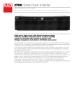
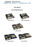
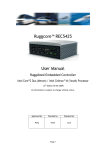
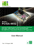
System Overview
1.4
System Architecture
RUBY-9717VGAR includes INTEL Q965 chipset, it supports the latest INTEL Core 2
Duo processors with 1066MHz front side bus; up to 8GB DDR2 800 SDRAM system
memory in four DIMM sockets; six SATA ports and ten USB 2.0 on RUBY9717VGAR.
4 Pin 12V
24 Pin ATX
Intel LGA775 CPU
533/800/1066 FSB
VGA
CRT
Dual Channel DDR2 667/800
SDVOB
DVI
Intel Q965 GMCH
SDVOC
ADD2 Slot
PCI BUS
PCI-Ex1 Slot
2 PCI Slots 32bit/33MHz
HD
Audio I/F
LAN Intel 82562
Intel 82566
HD AUDIO ALC262
Intel ICH8DO
SPI
SATA-300 X6
SPI BIOS
USBX8
USBX2
12 GPIOs
LPC BUS
FDD
KB&MS
COM1&2 RS232DB-9 ,
POWERED 5V&12V
COM3 RS232COM4
RS232/422/485
W83627HG#1
W83627HG#2
RUBY-9717VGAR Block Diagram
RUBY-9717VGAR User’s Manual
1-6
Hardware Configuration
Chapter 2
Hardware Configuration
This chapter indicates jumpers’, headers’ and connectors’ locations. Users may find
useful information related to hardware settings in this chapter. The default settings
are indicated with a star sign (Ì).
2.1
Jumper Setting
For users to customize RUBY-9717’s features. In the following sections, Short
meanscovering a jumper cap over jumper pins; Open or N/C (Not Connected)
means removing a jumper cap from jumper pins. Users can refer to Figure 2-1 for the
Jumper allocations.
Figure 2-1
RUBY-9717VGAR Jumper & Connector Location
RUBY-9717VGAR User’s Manual
2-1
Hardware Configuration
JP1/JP2 : COM1&COM2 RI / Power Function Selection
JP1、JP2
1-2
2-3
Function
VCOM
Ring Ì
JP3 : MFG Function Selection
JP3
OPEN
SHORT
Function
MFG OFF Ì
MFG ON
JP4 : COMS Clear Jumper setting
JP4
1-2
2-3
Function
NORMAL OPERATION Ì
CLEAN CMOS
JP6 : COM1& COM2 VCOM Power Selection
JP6
1-2
2-3
Function
VCC Ì
+12V
JP7 : COM3 RI/Power Function Selection
JP7
1-2
2-3
Function
+12V
MODEM RING IN Ì
JP8 : COM3 RI/Power Function Selection
JP8
1-2
2-3
Function
+12V
MODEM RING IN Ì
JP9 : COM2 RS232/485/422 Selection
JP9
RS-232
RS-422
RS-485
Function
5-6、9-11、10-12、15-17、16-18 Ì
3-4、7-9、8-10、13-15、14-16、21-22
1-2、7-9、8-10、19-20
Ps. Pin 19、20、21、22 can be saved, but S/W should keep the COM2 RTS signal low when using
RS-422
RUBY-9717VGAR User’s Manual
2-2
Hardware Configuration
JP10 : AT /ATX MODE
JP10
OPEN
SHORT
2.2
Function
ATX Power Mode Ì
AT Power Mode
Connector Allocation
I/O peripheral devices are connected to the interface connectors on this Industrial
Mainboard.
Connector Function List
Connector
J1
J2
J4
J5
J6
J7
J9
J10
J11
J13
J14
J17
J18/J21
J19/J22
J24
J25
J26
J27
J28
J31
J32
J33/J43/J44/ J45
J35
J37
J38
J39
J40
J41
J42
Function
CRT Connector
DVI Connector
PS/2 K/B and Mouse connector
COM1 COM2 Connector
Audio Jack x3
LAN+USBx2
CPU Fan-4P
Power 12V Connector
ADD2 Slot
PCI Slot2
PCI Slot1
Fan_3P
DDR2_Slot_Chnnel 0
DDR2_Slot_Chnnel 1
GPIO Connector
FDD Connector
Fan_3P
SATA Connector_6
SATA Connector_5
SATA Connector_1
SATA Connector_2
USB Connector
FrontPanel Connector
ATX Power Connector 24P
PCI-Ex4 Connector
SATA Connector_3
SATA Connector_4
COM3 Connector
COM4 Connector
RUBY-9717VGAR User’s Manual
Remark
*
*
*
*
*
*
*
*
2-3
Hardware Configuration
Pin Assignments of Connectors
J6 : AUDIO Connector
PIN No.
1
2
3
Signal Description
Line Out/IN
HeadPhone Out
MIC IN
J9 : CPU FAN 4P Connector
PIN No.
1
2
3
4
Signal Description
GND
+12V
SENSE
Control
J10 : Power 12V Connector
1
2
3
4
PIN No.
1
GND
2
GND
Signal Name
RUBY-9717VGAR User’s Manual
PIN No.
3
+12V
4
+12V
Signal Name
2-4
Hardware Configuration
J17/J26 : 3P Fan connector
12 3
Pin No.
1
2
3
Signal Name
GND
+12V
SENSE
J24 : 8-bit GPIO
PIN No.
1
3
5
7
9
11
13
Signal Description
GPIO16
GPIO5
GPIO20
GPIO12
GPIO36
GPIO10
GND
PIN No.
2
4
6
8
10
12
14
Signal Description
GPIO4
GPIO18
GPIO8
GPIO0
GPIO37
GPIO14
+5V
PIN No.
2
4
6
8
10
Signal Description
USB power (5V)
USB DATA BUSB DATA B+
Ground
Ground
J33/J43/J44/J45 : USB Connector
10
2
1
7
PIN No.
1
3
5
7
9
Signal Description
USB power (5V)
USB DATA AUSB DATA A+
Ground
N/A
RUBY-9717VGAR User’s Manual
2-5
Hardware Configuration
J35 : FrontPanel Connector
PIN No.
1
3
5
7
Signal Description
SATA LED+
POWER LED+
Power ON+
Reset+
PIN No.
2
4
6
8
Signal Description
SATA LEDPOWER LEDPower ONReset-
J41/J42 : COM3 & COM4 connector
PIN No.
1
2
3
4
5
6
7
8
9
10
Signal Description
DCD (Data Carrier Detect)
RXD (Receive Data)
TXD (Transmit Data)
DTR (Data Terminal Ready)
GND (Ground)
DSR (Data Set Ready)
RTS (Request to Send)
CTS (Clear to Send)
RI (Ring Indicator) or +12V
N/C
J53 : Audio CD- in Connector
4
1
PIN No.
1
2
3
4
Signal Description
CD-Left
CD-GND
CD-GND
CD-Right
RUBY-9717VGAR User’s Manual
2-6