1
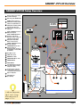
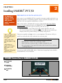
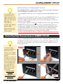
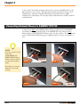
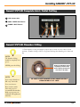
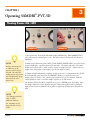
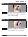
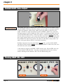
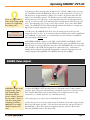
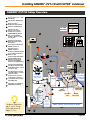
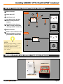
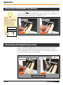
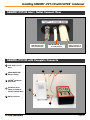
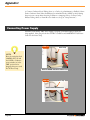
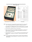
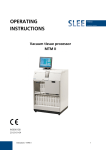
TABLE
OF
CONTENTS
Chapter 1
SAMDRI®-PVT-3D Overview
SAMDRI®-PVT-3D
SAMDRI®-PVT-3D Setup Overview
Chapter 2
Installing SAMDRI®-PVT-3D
Preparation of Installation Site
Installation of the SAMDRI®-PVT-3D
Chapter 3
8
Operational Notes
Safety Devices
Installation
Loading
Chamber Cooling
Solvent Exchange (PURGE)
Critical Point Passage (HEAT)
Pressure Reduction (BLEED)
Typical Cycle
Care of Dried Samples
Chapter 5
4
4
Operating SAMDRI®-PVT-3D
Operating SAMDRI®-PVT-3D
Chapter 4
2
3
12
12
12
13
13
13
15
16
16
Theory of Critical Point Drying
The SAMDRI®-PVT-3D
Preservation of Delicate Ultrastructure
Sample drying at the Critical Point (SAMDRI®-ING Method)
Transitional Fluid
Sample Preparation before SAMDRI®-ING
Water Exclusion
Chapter 6
Illustrations
Chapter 7
Maintenance and Support
Regular Maintenance Schedule
Chamber Care
LCO2 Filter Assembly
LCO2 T-filter Element Installation
FAQ
Optional Accessories
Warranty
Repackaging for Shipment
17
17
17
18
19
19
21
22
23
24
26
27
30
30
31
Appendix
A. Chamber Lamp Replacement Installation
B. Purge Line Filter Replacement Instruction
C. Installation of the SAMDRI®-PVT-3D (with SOTER™ Condenser)
32
36
38
Illustration Index
50
User's Notes
51
Check Out Data Sheet
Warranty
CHAPTER 1
®
SAMDRI -PVT-3D Overview
SAMDRI®-PVT-3D
THE ADVANCED MANUAL CRITICAL POINT DRYER
tousimis® Catalog #8755B (SAMDRI®- PVT-3D)
Page 2
1
SAMDRI®-PVT-3D Overview
SAMDRI®-PVT-3D Setup Overview
1
Remote LCD readout display
of LCO2 Tank Weight
2
Main LCO2 Tank ON/OFF Valve
3
Oil/Water Filter Housing of
LCO2 Filter Assembly (#8784)
4
T-Filter w/ 0.5µm Element of
LCO2 Filter Assembly (#8784)
5
High Pressure Hose, 5ft
(other lengths available upon
request)
6
COOL / BLEED Exhaust Hose,
White (1/4” ID), 6ft
7
COOL / BLEED CO2 Exhaust
Vented to either Hood,
Exhaust Conduit, or Outdoors.
8
120V Properly Grounded
Outlet (from either Wall
Outlet or Transformer)
9
PURGE / VENT Exhaust Hose,
Clear (1/4” ID), 6ft
Exhaust Conduit
1/4” Male
Hose Barb
1
3
2
Outdoors
4
PURGE/VENT Exhaust Hose
10 routed to either an
Hood
7
Erlenmeyer Flask, a Carboy (1
gal minimum) or Solvent Drain
(if available)
5
6
17
11 FILL Meter Valve
16
∗
12 COOL Meter Valve
13 BLEED Meter Valve
8
15
14 PURGE/VENT Meter Valve
15 POWER SWITCH
16 HEAT SWITCH
TABLE TOP
30”(76cm)
Minimum
Depth
LCO2 Tank
Approximately
50% Usable
17 Tare Weight Varies (Consult
your LCO2 supplier. Usually
stamped on tank)
18 Ceramic Heater or Heater
Jacket maybe required in a
cold tank placement position
19 Siphon or Dip Tube
20
LCO2 Tank Scale
(trc# 8770-54)
9
18
CO2 Gas
12
CO2 Liquid
13
14
10
TABLE TOP 20” (51cm) Minimum Width
∗ At Room Temperature
(20°C - 24°C), average
LCO2 tank pressure is
800psi (+/- 5%).
11
19
20
Page 3
CHAPTER 2
2
®
Installing SAMDRI -PVT-3D
See Appendix C
(p.38), to Install
SAMDRI®-PVT-3D
with optional
SOTER™ Condenser
(# 8777)
PREPARATION OF INSTALLATION SITE
Upon receipt of your SAMDRI®-PVT-3D, unpack the instrument carefully and check for any
damage that may have occurred during shipment. Report (by Email [email protected] or Fax
#301-881-5374) any irregularities immediately to tousimis®.
Insist on clean surfaces. Minimum table top space of approximately 20"(51cm) Width x
30"(76cm) Depth should be allotted for the SAMDRI®-PVT-3D with an additional
12"(31cm) x 12"(31cm) of floor space for the LCO2 tank scale (See p.3).
• Use bone-dry (min. 99.8% Purity) LCO2 with a syphon (dip-tube) tank* only.
• Do not use pressurized LCO2 with Helium or any other high pressure substitute gas.
• Properly secure LCO2 tank according to your facility’s safety protocol.
* BOC gas suppliers refer
to 99.8% purity grade as
“2.8” grade.
• Always order LCO2
tanks with Siphon or dip
tubes.
• Air Products gas
suppliers refer to 99.8%
purity grade as “CP”
grade.
• Minimum LCO2 purity
required is 99.8%.
Tank pressure typically reads 800psi (±5%) at room temperature. The amount of LCO2 in
tank is best monitored with a LCO2 tank scale (See accessories p.30).
Typical nominal LCO2 tank weights for Net 50lb LCO2 tanks:
• Full tank: 140 to 170 lbs / Tare of tank: 90 to 120 lbs.
• Most of the time, you may use 50% of a 50lb. net weight CO2 tank.
• It is good practice to have spare LCO2 tanks stored in reserve in case a tank runs
out during mid process.
A properly grounded 120V/50-60Hz outlet or Transformer (Step-up/Step-Down) should be
located within 4ft (1.2.m)of install site.
POWER Connection to SAMDRI®-PVT-3D
1 AC (BLACK)
COLD
2 GROUND
120AC/60HZ
3 AC (WHITE)
HOT
1
Page 4
2
3
Installing SAMDRI®-PVT-3D
INSTALLATION OF THE SAMDRI® -PVT-3D
This SAMDRI®-PVT-3D is supplied with the basic accessories for operation with LCO2 as
a transitional fluid (for optional accessories, see p.30).
** LCO2 tanks used in
most facilities have tare
weights ranging from 90 120lbs (40 - 55kg) and are
delivered as "full" with net
50lbs (23kg) of
compressed CO2.
Generally, 50% of the net
LCO2 is useable.
Monitor the LCO2 tank
weight via a LCO2 Tank
Scale (#8770-54).
1. Install SAMDRI® within 4 feet (1.2m) of a properly grounded (120V/50-60Hz) electrical
outlet.
2. Position a LCO2 tank with dip tube within 5 feet (1.5m) of the SAMDRI®-PVT-3D. For a
longer high pressure hose length, (see p.30), trc #8770-33. The LCO2 tank should be
mounted on a 400lb (182kg) capacity floor scale w/ remote LCD2 display (trc #8770-54) to
easily monitor LCO2 supply**.
3. Pressure gauges or regulators should not be installed between the LCO2 supply tank and the
SAMDRI®-PVT-3D LCO2 Connect Inlet. The stainless steel-sheathed high pressure hose
accompanying the SAMDRI® is fitted with a CGA-320 female hex coupling which accepts a
3/4" plastic gasket (supplied) and joins the hose directly to the CGA-320 threaded male
coupling at the tank top (See p.24). ALL LCO2 tanks should be equipped with a rupture
disc. All LCO2 fittings and gasket surfaces should be kept clean and dry.
NEVER OVER-TIGHTEN FITTINGS...TUBING ATTACHED MAY BE DAMAGED.
Connecting High Pressure Hose to SAMDRI®-PVT-3D
4. Attach the HIGH PRESSURE HOSE onto the LCO2 CONNECT INLET. Gently tighten
the High Pressure Female Connector using the two open-end wrenches supplied (one on the
hose and the other on the Inlet). Stop at the feel of first resistance; re-tighten if necessary,
should you hear a leak.
To attach LCO2 highpressure hose end fitting to
the PVT-3D “LCO2
Connect”, use the supplied
9/16" and a 1/2" open-end
wrenches.
First, slide 1/2" wrench over
1/2" fitting as shown in the
photo. The 1/2" wrench will
be used to hold the “LCO2
Connect Assembly” steady
as you gently tighten the
high pressure hose end
fitting snugly onto each of
the flare connects with a
9/16" wrench.
DO NOT OVERTIGHTEN
NO TEFLON® TAPE
NECESSARY
High Pressure
Hose
STEP 1
LCO2 CONNECT
INLET
STEP 2
9/16" open-end
wrench
1/2" open-end
wrench
STEP 4
STEP 3
Page 5
Chapter 2
5. The tousimis® LCO2 Filter Assembly (catalog #8784) is factory installed directly onto the
high pressure hose (See p.24-25). This helps prevent sample contamination from oil, water
and particulates. Change the Oil/Water Filter Element (# 8784A) with every 500lbs
(226.8kg) LCO2 tanks changes. The secondary 0.5µm T-Filter Element (# 8783B) should be
annually replaced.
Connecting Exhaust Hoses to SAMDRI®-PVT-3D
6. Attach the 6ft White COOL/BLEED Exhaust Tubing provided to the COOL/BLEED
CO2 Exhaust Outlet on the left-hand side of the SAMDRI®-PVT-3D, and the 6ft Clear
Exhaust Tubing to the PURGE/VENT Exhaust outlet (See photos below). The tubing should
be free of kinks which could block passage of rapidly exiting noisy CO2 gas or solid flakes of
CO2.
NOTE:
It is best to secure both the
ends of the
COOL/BLEED and
PURGE/VENT Exhaust
tubing so that the ends do
not move during exhaust
modes.
COOL/BLEED
CO2 Exhaust
STEP 5
STEP 6
STEP 8
STEP 7
Be careful not to obstruct
exhaust hose I.D. when
securing.
Page 6
PURGE/VENT
Exhaust
Installing SAMDRI®-PVT-3D
Samdri®-PVT-3D Complete Inlet / Outlet Setting
1 LCO2 Connect Inlet
2 COOL / BLEED CO2 Exhaust
3 PURGE / VENT Exhaust
1
2
3
Samdri®-PVT-3D Chamber O-Ring
7. Check chamber, O-ring and windows; inspect unit to insure it is free of dust, oil and
moisture. Chamber O-ring is NOT to be greased, but keep the chamber groove clean and
dry.
NOTE:
The chamber O-Ring
should lie completely in its
groove.
NEVER grease the O-Ring.
O-Ring (trc #8770-51) should
be properly seated and dry
prior to placing Chamber lid
onto Process Chamber.
NOTE:
Do not expose chamber to
HF or any other Acids.
BE SURE TO KEEP CHAMBER O-RING GROVE AND FACE
CLEAN AND DRY AT ALL TIMES.
Do not use Acetone.
Please consult tousimis
before using any nonrecommended intermediate
fluids or process any nontraditional CPD application
material(s)
Page 7
CHAPTER 3
3
®
Operating SAMDRI -PVT-3D
Turning Power ON / OFF
POWER OFF
POWER ON
1. Turn power ON. Power light and chamber light will illuminate. Allow SAMDRI®-PVT3D to warm up for 3 minutes prior to use. This allows time for the internal valve heaters to
equilibriate.
NOTE:
Pressure measurement is
no indication of the
amount of LCO2 left in
the tank. The same PSI
reading may be noted even
after the liquid CO2 drops
below the level of the
siphon tube.
2. Make certain all metering valves (FILL, COOL, BLEED, PURGE/VENT) are in the closed
position (hand tight). Open the main LCO2 tank valve. The Siphon (dip-tube) LCO2 tank
should have between 25 lbs - 50 lbs (13.6 kg -23 kg) net weight of LCO2. (Subtract the tare
weight of the tank from the tank weight to get the net weight of LCO2).
3. Sample should be dehydrated completely in high purity (99.5+% minimum purity) alcohol.
Pour enough high purity alcohol in the SAMDRI® chamber to completely cover your
sample(s) prior to transfer. Now, transfer your sample into the process chamber. Make the
transfer quickly in order to avoid the samples’ exposure to air and moisture.
The chamber O-Ring should lie completely in its groove. NEVER grease the O-Ring. Place
the chamber lid down over the chamber using the 3 knurl nuts; tighten each by hand with
equal pressure. Never use channel locks or pliers for tightening the knurl nuts. Always hand
tight!
NOTE:
* Use Ultrapure Alcohols
only! (i.e. I.P.A.,
Methanol, Ethanol).
Use minimum 99.5%
purity Alcohols for best
results.
Page 8
Operating SAMDRI®-PVT-3D
COOL Valve Adjust
COOL Valve
COOL MODE
4. Open COOL valve to approximately the 0.50 position (See metering valve illustration, p.
21). The temperature of the chamber should drop to near 0°C from room temperature in
approximately 1 minute. (The cool rate is a function of the amount of LCO2 running
through the COOL VALVE.) Usually a 0.50 setting on the COOL VALVE is satisfactory. It
is normal to hear the COOL Exhaust making audible noise as it exhausts from white tubing.
Close COOL VALVE when temperature reaches 0°C.
FILL Valve Adjust
FILL Valve
FILL MODE
5. Open FILL metering valve slowly until the chamber is full. LCO2 will enter the process
chamber mixing with the high purity alcohol (A bubble (meniscus) will travel across the
quartz viewing window indicating the chamber is full). Maintain the FILL valve open to a
setting of about 0.50 turns (this setting could vary as per use of the metering valve).
Page 9
Chapter 3
PURGE-VENT Valve Adjust
PURGE-VENT Valve
PURGE MODE
6. Keep FILL valve open. To exchange all the ethanol with LCO2 within the chamber; slowly
open the PURGE / VENT metering valve (exhaust) you can visually see movement (from left
to right) in the chamber. Make sure the “liquid” level in the chamber is always above the
sample. The FILL rate adjust should always exceed the PURGE / VENT rate to insure that
the sample remains covered in a liquid state. Place a carboy or an Erlenmeyer Flask at the end
of the clear PURGE exhaust tube to collect waste alcohol. Continue in PURGE mode until
all of the ethanol is exhausted. To be certain that all the ethanol has been purged, hold a clean
piece of paper (glycine paper works best) about four inches from the exhaust tube and collect
the solid white CO2 that is being emitted. The solid CO2 will sublime, and any visible “wet”
marks on the paper indicates that there is still ethanol remaining.
If chamber temperature rises above 10°C during PURGE mode, open the COOL VALVE
(this will not interfere with the PURGE mode) until the chamber is cooled to 0°C; then, close
the COOL valve and continue purging.
7. After ethanol is purged, close PURGE / VENT metering valve. Keep the FILL valve open
to insure chamber is full with LCO2. Note that a meniscus will travel across the viewing
window, indicating that the chamber is full. Close the FILL metering valve.
Turning HEAT ON / OFF
HEAT OFF
Page 10
HEAT ON
Operating SAMDRI®-PVT-3D
Never over tighten Meter
Valves when closing to 0.00
position. Over Tightening
may damage valves.
tousimis®
EQUILIBRIUM
BLEED MODE
8. At this point, all the metering valves should be in the “CLOSE” (0.00) position (see page
21). Turn HEAT switch ON. HEAT light will go ON. As the temperature (°C) increase, so
will the pressure. At approximately 1,350 psi (±5% @ 20°C), the pressure relief valve will
begin to vent the chamber pressure. The chamber’s pressure will be maintained above the
critical pressure for CO2 (1,072 psi). As the temperature passes the critical temperature for
CO2 (31°C), the heater will cut off (indicated by the heat light turning OFF) between 33°C 39°C. The temperature may coast up to 44°C; this is normal. Do not turn off the HEAT
switch. The SAMDRI®-PVT-3D will automatically maintain the chamber at a temperature
higher than the critical temperature (31°C) of CO2.
9. At this point, the SAMDRI®-PVT-3D is above the critical pressure (1,072 psi) and
temperature (31°C) for CO2. It can maintain itself automatically at the tousimis® equilibrium
state indefinitely. For best results, we recommend that you wait 4 minutes in equilibrium
before proceeding to BLEED mode.
10. POWER and HEAT switches are ON. FILL, COOL, BLEED and PURGE / VENT
metering valves are closed. Slowly open the BLEED metering valve to the BLEED meter valve
adjust position noted on the Check-Out Data Sheet. The initial BLEED flow rate via the flow
meter should be 8-10 SCFH (Fast decompression could result in CO2 “condensation”).
Chamber heater will cycle ON and OFF automatically to maintain temperature above the
critical temperature during BLEED. Close BLEED metering valve at 400psi.
BLEED Valve Adjust
BLEED Valve
SAMDRIed samples could
be hygroscopic; coating
with conducting film
immediately will best
preserve surfaces of interest
for your studies. However,
even after coating with a
conducting metal layer <
100Å thick, your sample
should be kept dry and
clean.
11. Open the PURGE / VENT metering valve to at least 0.50 setting to reduce chamber
pressure to 0 psi. The pressure will reach 0 psi (atmospheric pressure) in 2-3 minutes, loosen
the 3 Chamber Knurl Nuts evenly, by hand. Remove your sample and store in a dry
environment (i.e. vacuum, desiccator, etc) for further processing.
12. You may begin your next process run immediately (if desired).
13. After last process run of the day, make certain the chamber is clean and O-ring is in place.
Place lid on and tighten (by hand). Close the LCO2 main tank valve and open all valves of
the SAMDRI® to “drain” them from any residual line pressure, then close all the valves.
Clean the SAMDRI® surfaces. Turn Power OFF.
Page 11
CHAPTER 4
Operational Notes
4
SAFETY DEVICES
The SAMDRI®-PVT-3D sample process chamber is a high pressure metal alloy vessel with
viewing ports designed to withstand the pressures used in the critical point drying process. To
ensure additional operator safety, the following features are incorporated:
• A mechanical Automatic Pressure Control System (APCS) which will maintain the
chamber at a pressure between 1,350 psi ±5% (see Check-Out Data Sheet for your
dryer’s pressure relief valve specs).
• A rupture disc which will be activated (2,000 psi at 20°C) if the mechanical APCS
should fail (see factory check-out data sheet for the setting(s) of your unit.)
• Quartz ports which will crack along the crystal line, rather than shatter, should they
become unduly stressed (Immediately replace chamber lid if window becomes
cracked).
• Metal-alloy (sintered stainless steel) filters placed internally along both the inlet and
exhaust paths, preventing solid particles from fouling the gas lines/valves/fittings.
• An electronic heating system which is governed by two thermostats: one to maintain
the chamber during critical point passage at temperatures 37°C ± 2°C (see factory
check-out data sheet for your unit) and a second safety thermostat to shut off all
heating should a failure bring the chamber temperature near 49°C ± 3°C.
• A bulb and a translucent diffuser plate below the sample chamber which illuminate
chamber contents for easy viewing.
INSTALLATION
The SAMDRI®-PVT-3D is supplied with all necessary internal accessories for operation with
pressurized LCO2 as a transitional fluid. The user may also find it helpful to mount the
LCO2 cylinder on a tank scale (#8770-54) to monitor transitional fluid supply (by weight, not
pressure!), since only approximately 50% of the original net LCO2 may be used.
The SAMDRI®-PVT-3D connects to a standard 120V/50-60Hz, 15 Amp grounded outlet
and can be used wherever space permits. Waste alcohol can be collected into a carboy or an
Erlenmeyer Flask before the venting of the CO2 commences. The work area should be clean
and dry at all times.
LOADING
Methanol may also be used
as an intermediate fluid
Page 12
An adequate amount of intermediate fluid (Ultrapure Alcohol*, 99.9%+, enough to cover the
sample and holder) should be poured carefully into the chamber before placing your samples
into the chamber. This will minimize surface evaporation of the dehydrating intermediate
fluid (ethanol) from the sample. This is done at room temperature to avoid moisture
absorption from the atmospheric environment.
Operational Notes
CHAMBER COOLING
The tousimis® cooling capability of the SAMDRI®-PVT-3D may be exercised at any time, for
it is an entirely independent operation from FILL or PURGE/VENT. The chamber is
brought down to a temperature of approximately 0°C or below (Consult Check-Out Data
Sheet for your unit). The LCO2 tank should have at least 50% net weight of LCO2 for proper
COOL operation.
Chamber cooling is necessary to ensure filling with the liquid phase of the transitional fluid
(LCO2). Cooling also insures expulsion of the gas phase ahead of the liquid phase in the
pressure hose connecting the transitional fluid tank to the SAMDRI®-PVT-3D inlet circuit.
CO2 exiting from the COOL/BLEED Exhaust hose may appear in solid flakes as it
encounters the lower pressure environment. A 6ft (1/4” I.D.) white static free exhaust tubing
reduces the noisy rapid expansion of the LCO2 exhaust. This is a standard accessory.
SOLVENT EXCHANGE (PURGE)
SUGGESTED TEST TO
VERIFY COMPLETION
OF PURGE:
Since more adiabatic
cooling usually takes place
near the exhaust orifice of
the unit (evidenced by
white flakes of CO2, which
will form at -79°C), and
since intermediate fluids
such as pure ethanol have
even lower freezing points,
these fluids will be flushed
out as liquids. A soft, dry
coated paper held
momentarily in the
exhausting stream will catch
the white solid flakes of
CO2, and when shaken out,
will show "wet" spots and
indicate that there is
remaining alcohol to be
purged.
After cooling the chamber, transitional fluid (LCO2) may now be allowed to simultaneously
enter and leave the chamber. This process mode of incoming LCO2 and outgoing alcohol and
CO2 is called PURGE. Characteristics visible to the operator during the PURGE mode are as
follows:
• The intermediate fluid (alcohol) will appear as “oily currents” (schlieren patterns)
within the chamber (especially forwards the onset of PURGE).
• The intermediate fluid will appear as a liquid or a slurry when exiting through the
clear PURGE Exhaust hose. Once thoroughly exchanged, the chamber liquid will be
perfectly clear; the exiting CO2 will be solid white.
The Purge rate is manually adjustable with the PURGE / VENT valve, and should be set by
the operator to allow for a steady flushing of transitional fluid without letting the liquid level
drop away from the top chamber window.
A warming trend will be noted during the PURGE mode since the incoming fluid originates
at room temperature. The operator should occasionally check the chamber temperature, and
open the COOL valve as necessary, ensuring that the purging continues in the liquid state. It
is best to keep the temperature between 0°-10°C during the PURGE mode.
The purge time required for complete solvent exchange is not standardized, but is dependent
upon the size, density, and cellular characteristics of the sample. Exchange in a mono-layer of
cells can be completed within several minutes, whereas large semipermeable structures may
require 15 minutes. Generally, 24 samples of a size 4mm x 6mm x 2mm accommodated by a
Sample Holder (tousimis® catalog #8763) will require about 10 minutes; these purge times are
only suggested, however, and should be established in each case by process operator.
CRITICAL POINT PASSAGE (HEAT)
When all the intermediate fluid permeating the sample has been replaced by LCO2, purging
and cooling are terminated. Make sure the chamber is completely filled with LCO2. Return
to FILL again, if necessary. Heat is now applied to the chamber, elevating the transitional
fluid to above its critical temperature and pressure. During the HEAT mode, the CO2 may
appear as oily currents due to the heat causing variations in LCO2 densities and thus the
Page 13
Chapter 4
Schlieren pattern appearance.
NEVER use a LCO2 tank if
it is kept outside in the
winter. Bring it to room
temperature for 2-3 days
before use; otherwise, due
to low LCO2 tank
temperature, the tank will
not supply the SAMDRI®
with LCO2 at the proper
pressure.
The HEAT mode is thermostatically controlled to maintain a temperature at a safe margin
above the critical values, yet low enough that thermal destruction (above 55°C) of any
biological sample does not occur.
The chamber pressure increases relative to the increase in temperature. It is likely that the
critical pressure will be reached before the critical temperature if the chamber was completely
filled with LCO2 when heat was applied. The APCS is factory-set for 1,350 (±5% @ 20°C)
(see factory check-out data sheet) and will keep the chamber below 1,600 psi until the
chamber temperature rises above the critical temperature.
Typical Paths that Critical Point Passage May Follow During
"Heat Mode"
2000
Safety Control
(Rupture Disk)
1800
SPCM
1400
1200
1072 psi
CO2 Critical Pressure
1000
Automatic
Temperature
Control
CO2 Critical Temperature
Chamber Pressure (psi)
1600
800
600
Pressure range of
Liquid CO2 at room
temperatures
(700psi - 900psi)
400
200
HEAT ON
0
5
10
15
20
25
30 31.3°C 35
Chamber Temperature (°C)
Page 14
40
45
50
Copyright tousimis®
Operational Notes
PRESSURE REDUCTION (BLEED Mode)
Once the critical point has been passed with an adequate margin of safety, the CO2, which is
now in a dense vapor state, is exhausted slowly from the process chamber.
TEMPERATURE
(°C)
Typical Chamber Temperature during Pressure Reduction (BLEED)
44
42
40
38
36
0 1
2 3
4 5 6
7 8
9 10 11 12
TIME (Minutes)
Typical Range of Paths that Pressure Reduction May Follow
in the SAMDRI®-PVT-3D
1400
CHAMBER PRESSURE (psi)
1200
1000
800
At 400 psi, VENT mode may be activated.
600
400
200
0
0
1
2
3
4
5
6
7
8
9 10 11 12 13 14 15 16 17 18 19 20 21 22 23 24
TIME (Minutes)
Page 15
Chapter 4
TYPICAL PROCESS CYCLE
A typical process cycle, including 7 minutes of purge time, might run for about ½ hour, as
shown in the following, and may use 1.5lbs (0.7kg) of CO2.
Typical Drying Cycle
TIME (minutes)
0
COOL
Load
FILL
Cool
5
Fill
PURGE
(from 5 to 10 minutes)
Purge
TYPICAL
SAMDRI®-PVT-3D
DRYING CYCLE
12
Critical Point Passage
HEAT
Pressure Reduction
26
BLEED
SAMDRI Modes
VENT
36
Copyright tousimis®
CARE OF DRIED SAMPLES
After drying, care should be taken to prevent damage to the sample surfaces. It is
* Note that the SAMDRIed recommended that the sample be attached* to a tousimis® 10 mm diameter or Cambridge
Biological samples could
1/2” stud and, as soon as possible, coated with the appropriate conducting layer. SAMDRI®absorb certain glues! DO
ed biological samples are receptive to a metal coating in a vacuum and do not require any
NOT USE glue to mount
preparatory carbon coating. If the sample cannot be further processed immediately after
your sample since it will
drying, it should be stored in an isolated and desiccated environment. After coating, samples
diffuse into the dried
should be maintained in a dry environment to prevent changes as a result of water absorption
sample.
or possible cracking of the coating layer.
Page 16
CHAPTER 5
Theory of Critical Point Drying
5
THE SAMDRI®-PVT-3D
The tousimis® SAMDRI®-PVT-3D is a critical point drying apparatus which through a series
of stages, the sample is processed by a technique which preserves and stabilizes the delicate
3-D morphology without freezing "rigid" chemical fixation (which alters the ultra-structure)
embedding (paraffin, plastics, epoxies, etc.).
PRESERVATION OF DELICATE ULTRASTRUCTURE
Sample Drying (SAMDRI®) at the Critical Point: In order to preserve 3-D structure, one
must avoid the sudden (air-drying) change of densities that occurs when the fluid
"embedding" the sample and permeating its ultrastructure is converted to gas. Most liquids
used to replace water in samples have a well-defined critical point -- a specific pressure and
temperature at constant volume for each of them. At the critical point the densities of the gas
and liquid phases of the transitional fluid are equal; therefore, a phase boundary does not
exist. After the critical point transition from the liquid to vapor phase has taken place, the
vapor phase can be removed (while above atmospheric pressure) and the dried sample
preserved without structural damages due to surface tension forces.
SAMPLE DRYING AT THE CRITICAL POINT (SAMDRI®-ING)
METHOD
SAMDRI®-ING involves immersion of the sample in an intermediate fluid [ethanol] and its
substitution with LCO2, under pressure. The LCO2 is automatically converted to its gaseous
phase at the critical point in the high pressure chamber and removed at temperatures higher
than 31.1°C, thereby avoiding the distortion resulting from evaporation boundaries or
thermal expansion.
Typical Paths that Critical Point Passage May Follow during "Heat Phase" (p. 14) shows the
isotherm for CO2, including the critical isotherm at 31.1°C. Superimposed is a path which an
average critical drying cycle (SAMDRI®) can follow, divided here into four stages:
1st, the process chamber is COOLED and FILLED with LCO2, and maintained at
0°C ± 10°C;
2nd, the sample in the alcohol under pressure is PURGED of the alcohol with LCO2
until all traces of intermediate fluid [alcohol] are removed;
3rd, the chamber is heated automatically to a temperature above the critical
temperature of CO2. While the chamber volume is constant, there is an
accompanying rise of pressure to above the critical pressure of CO2, and the liquid
phase is converted to the gaseous phase;
4th, the gaseous CO2 is exhausted at a temperature above 31°C from the process
Page 17
Chapter 5
chamber, returning the sample to conditions of room temperature and pressure. The
sample is now critically point dried and ready for coating (metal film coating under
vacuum) and subsequent study in the SEM, TEM or electron probe X-ray
microanalyzer.
Isothermal of Carbon Dioxide and an Average Drying Path of
Sample in the SAMDRI®-PVT-3D
Isotherms
psi
atm
200
2700
50°C
PRESSURE (CO2)
2400
2100
Pressure Reduction
Bleed & Vent
150
1800
1500
100
1200
Critical Point
900
600
42°C
31.2°C
20°C
10°C
0°C
Critical
Point
Passage
50
300
Cool, Fill, & Purge
.1
BEGIN
Sample in
intermediate fluid:
ethanol or methanol
(for non-bio-samples)
at room temperature
and atmospheric
pressure.
.2
.3
.4
END
(After 35 minutes average time)
Dried sample now is in
air at room temperature
and atmospheric
pressure. Transfer to
moisture-free container.
.5
.6
.7
.8
DENSITY (CO2) g/cm3
.9
1.0
Possible paths during SAMDRI®-ing
Based on data by tousimis®
TRANSITIONAL FLUID
Liquid Carbon Dioxide (LCO2) is the preferred transitional fluid in critical point drying, since
it is easily accessible, more economical, less noxious, safe in a well-ventilated laboratory, and
provides more consistent results than any other transitional fluid. Only research grade or
filtered (see tousimis® combination filter, catalog #8784) "bone dry" LCO2 should be used.
Use of LCO2 requires a "dip" or Siphon tube in the CO2 cylinder tank, which provides liquid
at the tank outlet for the first 25-30 lbs. Tanks should be kept at room temperature for at
least 2-3 days prior to use.
Page 18
Theory of Critical Point Drying
LCO2 is shipped to your laboratory by your local distributor in steel cylinders. Please note the
tare weight and gross weight. You can only use about 50% of the net LCO2 since the dip
tube does not reach the bottom of the tank. Advise your supplier to never wash the empty
steel cylinder with water or leave it "in the yard" to accumulate pollutants. ALWAYS KEEP
SPARE FULL TANK IN RESERVE AT ROOM TEMPERATURE.
As you receive the LCO2, it is under pressure at 20°C, 750 to 900 psi. [While CO2 is a
respiratory stimulant, humans cannot breathe air containing more than 10% carbon dioxide
(at this level one could faint)]. Use the SAMDRI®-PVT-3D in a well-ventilated room, or
exhaust all CO2 into a working hood, exhaust conduit or the outdoors. Please consult your
laboratory regulations for exhaust requirements. Usually one to two pounds of LCO2 are used
for each process run. The critical temperature and pressure of pure CO2 are 31.3°C (88.84°F)
and 72.9 atm (1072 psi), respectively.
SAMPLE PREPARATION BEFORE SAMDRI®-ING
It is not the intention of this manual to present an extensive review of sample preparation
techniques. Certain samples present special problems in preparation and it is the
responsibility of the investigator to determine the best procedures in each case. It is the
general object of pre-critical point drying preparation steps to yield a sample in which the
histological ultrastructure is well-stabilized and free of water.
Most biological samples preparation could include:
FIXATION - Fixation generally utilizes an aldehyde such as formaldehyde*, glutaraldehyde*,
or acrolein** to provide rapid inter- and intra-cellular penetration and fixation, followed by
osmium tetroxide for further fixation.
* High purity or ultra-pure
fixatives are recommended.
(see tousimis® CAT. #1008
and #1011)
** Acrolein is a very
hazardous chemical. Avoid
its use unless there is no
other alternative, and then
use as per special
instructions in your
laboratory and after careful
reading of the MSDS.
STAINING AND SPECIAL TECHNIQUES - A fixative/stain such as aqueous solutions of
osmium tetroxide or silver is employed for SEM samples prior to dehydration and critical
point drying.
DEHYDRATION - The fixed sample is taken through a series of increasing concentrations of
a liquid such as ethanol, ending in a 100% ethanol of the highest possible purity (tousimis®
CAT. #5086). Transfer to room temperature before placing it in alcohol in the SAMDRI®PVT-3D chamber, and seal. Then you may initiate the process run.
WATER EXCLUSION
Water or oils remaining on the sample during critical point drying will not pass through the
critical point with the transitional fluid (since their critical pressures and temperatures are
different). Instead the water will evaporate from the sample surface and cause damage, or the
oils will cover the surface and render sputtering or shadowcasting with an electrically
conducting element impossible. Therefore, the sample must first be completely dehydrated, as
mentioned above, and precautions must be taken to avoid subsequent rehydration before
critical point drying (SAMDRI®-ING).
Page 19
Chapter 5
The final dehydration step involves three conditions for the 100% dehydrating liquid:
1. The dehydrating liquid should fill the vessel containing the sample in order to
reduce exposure to atmospheric moisture outside the SAMDRI®-PVT-3D.
Avoid the use of powdertype CaSO4 dehydrants in
the ethanol. We suggest the
use of clean silica gel-type
dehydrants to avoid sample
contamination from
"powdering" CaSO4
crystals.
2. The vessel should then be tightly stoppered with the lid (hand tighten).
3. The 100% fluid should be obtained from a newly-opened bottle of ultra-pure
ethanol or that it contain a dehydrant to insure no water contamination.
ALCOHOL IS HYGROSCOPIC.
General Form of Phase Boundaries
Pressure vs. Temperature for CO2
PRESSURE
Liquid
Solid
Pc = 1072psi
Critical Point
of CO2
Triple Point
ima
subl
ti o
n
Gas
Tc = 31°C
Pc = Critical Pressure of CO2
Tc = Critical Temperature of CO2
Page 20
Temperature
Copyright tousimis®
CHAPTER 6
6
Illustrations
Metering Valve w/ Vernier Handle Setting Example
The numerical markings
are arbitrary numerals for
the sole purpose of meter
valve adjustment position
reference.
1 complete counterclockwise 360 rotation
from the 0.00 starting
position is referred to as
the '0.25 position'.
0.00 Setting
0.50 Setting
1.00 Setting
Venting Precautions
LCO2 Inlet
Connect
COOL/BLEED CO2 Exhaust
PURGE/VENT Exhaust
#8784 LCO2 FILTER
ASSEMBLY
LCO2 Tank
Only use Flow Meter to
measure flow at onset of
BLEED mode only.
6ft (180cm)
6ft (180cm)
SCFH
VENT TO HOOD,
EXHAUST CONDUIT
OR OUTSIDE
DURING PURGE; COLLECT
WASTE ALCOHOL INTO A
CARBOY (1 GAL MINIMUM)
, AN ERLENMEYER FLASK
OR SOLVENT DRAIN
PURGE / VENT
EXHAUST HOSE CLEAR
TUBING, 6ft
20
16
12
8
4
0
COOL/BLEED EXHAUST HOSE
WHITE TUBING, 6ft
FLOW METER USED TO
CALIBRATE FLOW AT ONSET
OF THE BLEED CYCLE. SET
FLOW RATE to 8-10 SCFH
Page 21
CHAPTER 7
7
Maintenance and Support
Regular Maintenance Schedule
Maintenance Activity
Recommended
Frequency
Manual
Reference
trc® Catalog
Number
Keep Chamber Clean and Dry
Always
p. 23
N/A
Replace LCO2 Tank
After 50% net
p. 28 (FAQ)
tank consumption
Contact local
supplier
Replace LCO2 Oil/Water Filter in
LCO2 Filter Assembly
500lb LCO2 Use
p. 24-25
# 8784A
Replace T-Filter Element in
LCO2 Filter Assembly
1 Year*
p. 26
# 8770-83B
Chamber O-Ring
3 Months*
p. 7
# 8770-51
Internal Purge Line 0.5µm Filter
6 Months*
p. 36-37
# 8770-83
* May Vary Depending on Usage.
Page 22
Maintenance and Support
Chamber Care
NOTE:
* Use Ultrapure Alcohols
only! (i.e. I.P.A.,
Methanol, Ethanol).
Use minimum 99.5%
purity Alcohols for best
results.
* Ult
rapure Alcohol
Us
e only
hol
high purity alco
LINT FREE WIPES
99.5%+
NOTE:
Do not expose chamber to
HF or any other Acids.
Do not use Acetone.
Please consult tousimis
before using any nonrecommended intermediate
fluids or process any nontraditional CPD application
material(s)
NOTE:
BE SURE TO KEEP
CHAMBER O-RING
GROVE AND FACE
CLEAN AND DRY AT
ALL TIMES.
ACETONE
HF
VACUUM
GREASE
NEVER INTRODUCE ACIDS INTO CHAMBER
Page 23
Chapter 7
LCO2 Filter Assembly
THE tousimis® LCO2 FILTER ASSEMBLY (# 8784)
( 4 + 5 Figure Shown Below)
Part B
Installation Instructions
1. Uncouple CGA-320 S.S. nut from LCO2 tank. Close
main tank valve. Crack S.S. nut and bleed line pressure.
Make certain there is no pressure within the high pressure
hose.
Tighten
Hole if
Needed
2. Install filter element as shown in the diagram. (#8784A)
Push element steadily into upper housing orifice until
slight resistance is felt. Screw housing (Part B) onto upper
housing (Part A). Be sure that teflon® O-Ring is in place.
Rotate to Tight
3. The 0.5 µm T-Filter Element (# 8770-83B) is pre-installed
into T-Filter.
* Change LCO2 Filter Element (#8784A) with every 500 lbs of
LCO2 consumption, change T-Filter Element (#8770-83B)
every 1 year to insure proper filtration.
1
2
4
5
3
LCO2 Filter
Element
#8784A
Oil/Water
Filter
Housing
O-Ring
#8784B
8
LCO2 Tank w/
Siphon Tube
6
1
Main LCO2 Tank Valve
2
Gasket (Teflon® or Nylon)
3
CGA - 320 S.S. Nipple
4
Oil/Water Filter Housing w/
LCO2 Filter Element
(#8784A)
Page 24
7
5
T-Filter with
T-Filter Element (0.5 µm,
#8770-83B)
6
CGA - 320 S.S. Coupler Nut
7
Teflon® tape
8
High Pressure Hose to
Samdri®
IN
OUT
Part A
CAUTION: USE tousimis® LCO2 FILTER ELEMENT
(trc# 8784A) ONLY.
Operating pressure not to exceed 1000 psi
Maintenance and Support
LCO2 Filter Element Installation (#8784A)
STEP 1
After all of the pressure is safely bled
from high pressure line, unscrew
Oil/Water Filter Housing by hand.
STEP 4
Place new LCO2 Filter Element (#8784A)
into lower Oil/Water Filter Housing. Let
gravity hold element in place.
STEP 5
Carefully lower Oil/Water Filter Housing
over replacement element (#8784A).
STEP 2
Remove Oil/Water Filter Housing.
STEP 3
Position LCO2 Filter Element (#8784A)
into center of lower Oil/Water Filter
Housing.
STEP 6
Hand tighten the housing body together
firmly. O-Ring seats properly. Open
main tank valve and check for leaks.
Page 25
Chapter 7
LCO2 T-Filter Element Installation (#8770-83B)
STEP 1
STEP 2
After all of the pressure is safely bled
from high pressure line, unscrew T-Filter
cap using wrench.
STEP 4
T-Filter Gasket
(# 8770-83D)
Carefully remove T-filter element.
STEP 3
T-Filter Element
(# 8770-83B)
Top view of correctly installed T-Filter.
STEP 5
Install a new T-filter element (#8770-83B)
into center of T-filter housing.
STEP 6
NOTE:
Do not over-tighten
T-Filter Cap.
Hand tighten T-filter cap.
Page 26
Use wrench, tighten the T-filter cap firmly.
Open LCO2 tank valve and check for
leaks.
Maintenance and Support
FAQ
Should the LCO2 tanks be secured?
YES. It is recommended that:
The LCO2 Tanks be placed onto LCO2 Tank Scales (trc #8770-54) and secured as per your
facility safety regulations. Monitor the net LCO2 used. When you approach 50% LCO2
consumption, it is recommended that you replace the LCO2 tank with a new one. Always
keep several spare tanks of LCO2 in reserve.
Do I need an In-line regulator between the tank and the SAMDRI®-PVT-3D?
NO. A regulator is not needed between the LCO2 tank and the 3D. The 3D is designed to
simply operate from LCO2 direct tank pressure.
Is the chamber necessary to heat during BLEED mode?
YES. During the BLEED mode the HEAT switch should be kept ON. The HEAT mode will
maintain chamber temperature automatically above 31ºC and keep the process chamber dry.
How do I replace the #8784A filter elements?
To replace #8784A filter element, loosen and remove lower part B by turning counter
clockwise. Remove old element and replace with new (See illustration p.24-25).
How do I secure the chamber lid?
Evenly finger-tighten the chamber lid with the 3 Knurled Nuts. Use even and steady finger
pressure on all Knurl Nuts alternatively. Never use a non compatible tool or excessive force
(i.e.: never use a wrench, etc).
Should I use “High-Pressure Head” tanks such as Helium or other high-pressure
gases?
NO. Never use high-pressure tanks. Typical proper pressure range for LCO2 tanks are between
750 – 900 psi. Higher pressures may damage SAMDRI®-PVT-3D and / or cause failures.
Can I use lower purity alcohol or acid in chamber?
NO. ONLY USE ULTRA-PURE ALCOHOL (ETHANOL, METHANOL, I.P.A., etc.) IN
CHAMBER, NEVER ANY ACID! CONTACT TOUSIMIS PRIOR TO USING ANY
OTHER INTERMEDIATE LIQUIDS.
Is a siphon or dip tube type LCO2 tank necessary?
YES. It is essential that the LCO2 tank has a siphon or dip tube on order to deliver liquid and
not gaseous CO2. The SAMDRI®-PVT-3D will not operate properly without liquid CO2.
Page 27
Chapter 7
Why can I only use 50% of the net amount of LCO2 and not 100% of the net
LCO2 within a new LCO2 tank?
LCO2 is lost during the process for 2 reasons:
1) As the liquid level drops in the LCO2 tank, the gaseous head space created as the
liquid level drops is taken up via gaseous CO2 molecules.
2) Siphon (aka: dip-tubes) does not reach the absolute bottom of the LCO2 tank.
What can I do to check that the BLEED rate is properly set should it appear
unusually slow?
The flow rate should read 8 - 10 SCFH at the onset of the BLEED cycle. This setting should
yield at average of approximately 100-150 psi/min reduction in pressure. This pressure
reduction flow rate is the desired decompression rate between 1300 → 400 psi to avoid
condensation.
You may periodically measure the BLEED rate (if desired) via the Flow Meter supplied by
attaching the Flow Meter to the COOL/BLEED CO2 Exhaust Outlet via a short
(approximately 2') piece of Tygon tubing.
Flow Meter
What is the average FILL Time?
The FILL time should not exceed more than 2 minutes. Typically the chamber will FILL in
less than 1 minute.
What is the average PURGE time?
The PURGE time will vary according to the volume of ethanol in the chamber. It takes
approximately 7 minutes to purge 50% of the chamber volume (10-15ml Alcohol).
Page 28
Maintenance and Support
Is chamber pressure automatically regulated during Critical Point Passage?
YES. Chamber pressure will rise above 1072psi (Critical Pressure for CO2) and automatically
vent internally at 1350psi ±5% @ 20°C.
Is chamber temperature automatically regulated during Critical Point Passage?
YES. Temperature is maintained between 31°C-42°C automatically with HEAT switch ON.
Is there back-up pressure Safety?
YES. In addition to automatic internal pressure venting above the Critical Point. There is a
“rupture disk” which automatically vents entire system at 2000psi.
What grade LCO2 is best for the SAMDRI®-PVT-3D?
99.8% minimum purity.
May I replace or add parts without authorization from tousimis®?
NO. SAMDRI®-PVT-3D is a high pressure instrument with specific tolerances engineered
into the design. Please contact tousimis® for authorization prior to attempting any desired
changes.
What should I do if the initial COOL time is suddenly much slower than normal?
99% of the time the reason for this is lack of Liquid CO2. The SAMDRI® is designed to
COOL the process chamber via Liquid CO2 and not gaseous CO2.
Reasons that typically explain gaseous CO2 delivery:
1) The Liquid CO2 level has dropped below LCO2 tank siphon (aka: dip tube) and only
gaseous CO2 is being delivered. [Note: The best way to monitor LCO2 is via weight and not
pressure. It is best to monitor tank weight via a "LCO2 tank scale (trc#8770-54)”]
2) Gas supplier has delivered Gaseous rather than Liquid CO2 by mistake. This can happen as
the 2 tank types may look identical and the delivery/loading Gas Company staff accidentally
delivered the wrong tank type to your site.
The simpler solution is to replace the existing supply tank with a new LCO2 tank and initiate
COOL mode. If the same problem persists; please contact customer service at either
[email protected] or via tel# 301-881-2450.
Page 29
Chapter 7
OPTIONAL ACCESSORIES
Catalog #
Description
8777
SOTER™ CONDENSER
8760-01
Knurl Nut
8760-40
5 AMP Fuse
8770-10
Lamp, 120V/60Hz volt
8770-32
High Pressure Hose, 5 ft
8770-33
High Pressure Hose, 10 ft
8770-HPS
High Pressure Hose, Custom Length Up To 10m (33ft)
8770-45
Flow Meter - Use with any 1.25" dia. Samdri® Chamber (20 SCFH)
8770-50
Chamber Lid
8784
LCO2 Filter Housing for 8784A Filter Element
8784A
Replacement LCO2 Filter Element for 8784 Filter Housing
8784B
O-Ring for 8784 Filter Housing Seal
8784-05
Gasket for LCO2 Tank Connect
8770-83
Internal 0.5µm Brass Particulate Line Filter
8770-51
O-Ring for 1.25" Diameter Autosamdri® Chamber
8770-53
Power Cable, three prong, 120V/60Hz
8770-54
LCO2 Tank Scale, w/ Remote LCD Display (400lb capacity)
8770-55
LCO2 Tank Heater
8770-56
Step-Down Transformer, 220V → 110V
8770-57
Step-Up Transformer, 100V → 120V, 50/60hz
8761
Grid Holder, holds 12 grids.
8762
12 Sample Holder, each compartment measures 7.5 (dia.) x 6mm (ht.)
8763
24 Sample Holder, each compartment measures 4.5 (dia.) x 6mm (ht.)
8764
4 Sample Holder, each compartment measures 9 (dia.) x 16mm (ht.)
8766
Cover Slip Holder, for 9mm to 13mm diameter Glass Cover Slips
8766-01
Washer for Glass Slip Holder (for use with #8766)
8766-02
Stainless Steel Screens for Cover Slip Holder (for use with #8766)
8767
Cover Slip Holder, for 16mm to 22mm diameter Glass Cover Slips
8767-01
Washer for Glass Slip Holder (for use with #8767)
8767-02
Stainless Steel Screens for Cover Slip Holder (for use with #8767)
Contact tousimis @ 301-881-2450 or [email protected] for current pricing and availability, or
visit our web site at www.tousimis.com.
Page 30
Maintenance and Support
WARRANTY
The SAMDRI®-PVT-3D is warranted to the original purchaser for two years from date of
purchase against any defect in materials or workmanship. Should you have any questions,
please feel free to contact us. If it is determined that the unit should be returned for repairs to
our Service Department, we will send a written authorization for shipment. Parts and labor
are free of charge; shipping charges are to be paid by customer (insure instrument at current
list price).
DO NOT ship instrument via U.S. Mail. Use UPS, FedEx or other qualified shippers only.
Our mailing address:
tousimis research corporation
2211 Lewis Avenue
Rockville, Maryland 20851
USA
Our shipping address:
tousimis research corporation
Attention: Instrument Service Department
2211 Lewis Avenue
Rockville, Maryland 20851
USA
Telephone # 301-881-2450
Fax #301-881-5374
Email: [email protected]
REPACKAGING FOR SHIPMENT
After authorization for repairs is received (see warranty), this general rule may be followed in
repackaging a tousimis® instrument for shipment:
a) Attach identification tag to instrument. Tag should indicate owner name, the
model and 4-digit serial number of the instrument, and the type of the service or
repair desired.
b) Secure chamber lid over a properly seated O-ring and tighten 8-knurl nuts evenly.
Do not send the high-pressure hose or electrical power cord.
c) Place instrument in original container, if available. If original container and
packaging material is not available, new packaging may be purchased from tousimis
If original container is not used,
d) Wrap the instrument in bubble plastic.
e) Protect panel faces and instrument sides with foam or appropriate non-abrasive
cushioning material. Use a minimum 6” of shock-absorbing packing material around
all points of the instrument. Two double walled boxes are suggested for shipment;
BOX-WITHIN-A-BOX AT 350LBS. TEST STRENGTH.
f ) Use heavy duty shipping tape or metal bands to seal container.
g) Mark shipping container with "Delicate Instrument, Fragile", etc. and insure it.
Page 31
APPENDIX A
Chamber Lamp Replacement Installation
A
1. Turn the power switch "OFF" and unplug 120V power cord from the SAMDRI®-PVT-3D.
2. Disconnect 'PURGE / VENT’ Exhaust Hose from the SAMDRI®-PVT-3D.
PURGE / VENT Exhaust
Hose
3. Disconnect 'COOL / BLEED’ Exhaust Hose from the SAMDRI®-PVT-3D.
COOL / BLEED Exhaust Hose
Page 32
Chamber Lamp Installation
4. Close main LCO2 tank valve, bleed LCO2 High Pressure Hose. Disconnect 'LCO2 High
Pressure Hose' using supplied 9/16" Wrench and 1/2" Wrench from the SAMDRI®-PVT-3D
Connect Inlet.
Main Tank Valve
9/16” Wrench
LCO2 High
Pressure Hose
LCO2 Tank
with Siphon Tube
1/2” Wrench
5. Carefully pick up the front end of SAMDRI®-PVT-3D and gently rest on its back end.
6. Unscrew the 4 black rubber legs that secure the access panel in place.
Page 33
Appendix A
7. Remove and set aside the access panel. Note access panel orientation so that you may reinstall panel in the same direction upon procedure completion.
Access Panel
8. Locate the Chamber Lamp as indicated below.
SAMDRI®-PVT-3D Chamber View
Chamber Lamp (Cat# 8770-10)
Page 34
Chamber Lamp Installation
9. The Chamber Lamp is mounted into a "Bayonet" style lamp holder. Push Chamber Lamp
towards the lamp housing and twist to the left to uninstall lamp (As shown below).
10. Install a new Chamber Lamp (Cat# 8770-10). Please note that you may need to support
the Chamber Lamp housing with your free hand for support.
11. Re-install the access panel and re-connect power and all hose(s) prior to starting up
system.
Page 35
APPENDIX B
B
Purge Line Filter Replacement Instruction
1. Repeat Step 1-7 of previous section (Chamber Lamp Replacement Installation) in order to
remove access panel.
2. Locate the Purge Line Filter (# 8770-83) as indicated below. Note the Purge flow direction.
0.5µm Particulate
Purge Line Filter
(# 8770-83)
FLOW
SAMDRI®-PVT-3D Internal View
FLOW
7/16” Coupler
7/16” Coupler
Page 36
0.5µm Particulate
Purge Line Filter
(# 8770-83)
Purge Line Filter Replacement Instruction
Flow Direction
Purge Line Filter, 0.5 µm (#8770-83)
3. Disconnect Purge Line Filter by carefully holding Purge Line Filter steady with 9/16"
Open-end wrench while disconnecting both 7/16" couplers. Carefully remove old Purge Line
Filter and discard.
7/16” Wrench
9/16” Wrench
7/16” Wrench
9/16” Wrench
4. Install new Purge Line Filter paying attention to flow direction. Please note flow direction
on the Purge Valve MUST be installed in-line with flow direction indicated in previous
SAMDRI®-PVT-3D Chamber Plumbing picture.
NOTE:
It is recommended that
the "Purge Line Filter" be
replaced every 6 months
with regular use. Change
more frequently with
heavy use.
Please contact
[email protected]
with any questions.
5. Re-install access panel. Re-connect power and all connection hose(s) prior to starting up
system.
Page 37
Appendix C
®
™
Installing SAMDRI -PVT-3D with SOTER Condenser
This section is for
Installing
SAMDRI®-PVT-3D
with optional
SOTER™ Condenser
(# 8777). See
Chapter 2 (p.4) for
installing without
SOTER™ Condenser.
C
PREPARATION OF INSTALLATION SITE
Upon receipt of your SAMDRI®-PVT-3D, unpack the instrument carefully and check for any
damage that may have occurred during shipment. Report (by Email [email protected] or Fax
#301-881-5374) any irregularities immediately to tousimis®
Insist on clean surfaces. Minimum table top space of approximately 36"(92cm) Width x
30"(76cm) Depth should be allotted for the SAMDRI®-PVT-3D and optional SOTER™
Condenser with an additional 12"(31cm) x 12"(31cm) of floor space for the LCO2 tank scale
(See p.3).
Use bone-dry LCO2 with a syphon (dip-tube) tank* only. Do not use pressurized LCO2 with
Helium or any other high pressure substitute gas. Secure LCO2 tank according to your
facility’s safety protocol.
Tank pressure typically reads 800psi (±5%) at room temperature. The amount of LCO2 in
tank is best monitored with a LCO2 tank scale (See accessories p.37).
* BOC gas suppliers refer
Typical nominal LCO2 tank weights for Net 50lb LCO2 tanks:
to 99.8% purity grade as
“2.8” grade. Air Products
• Full tank: 140 to 170 lbs / Tare of tank: 90 to 120 lbs.
gas suppliers refer to 99.8%
• Most of the time, you may use 50% of a 50lb. net weight CO2 tank.
purity grade as “CP” grade.
• It is good practice to have spare LCO2 tanks stored in reserve in case a tank runs
Always order LCO2 tanks
out during mid process.
with Syphon (aka: dip)
tubes. Minimum LCO2
A properly grounded 120V/50-60Hz outlet should be located within 4ft (1.2.m)of set-up site.
purity required is 99.8%.
INSTALLATION OF THE SAMDRI® -PVT-3D
This SAMDRI®-PVT-3D is supplied with the basic accessories for operation with LCO2 as
a transitional fluid (for optional accessories, see p. 37).
1. Position a LCO2 tank with dip tube within 4 feet (1.2m) of the PVT-3D. For a longer high
pressure hose length, see p.37, trc #8770-HPS. The LCO2 tank should be mounted on a
** LCO2 tanks used in most 400lb (182kg) capacity floor scale w/ remote LCD2 display (trc #8770-54) to easily monitor
facilities have tare weights
LCO2 supply**.
ranging from 90 - 120lbs
(40 - 55kg) and are
2. No pressure gauges or regulators need be installed between the supply LCO2 tank and the
delivered as "full" with net SAMDRI®-PVT-3D LCO2 connect inlet. The stainless steel-sheathed high pressure hose
50lbs (23kg) of compressed accompanying the unit is fitted with a CGA-320 hex coupling which accepts a 3/4" plastic
LCO2. GENERALLY, 50% gasket (supplied) and joins the hose directly to the CGA-320 threaded male nipple at the tank
IS USEABLE. You are
top (See p.31). ALL tanks are equipped with a rupture disc. All LCO2 fittings and gasket
advised to monitor the tank surfaces should be kept clean and dry.
weight.
NEVER OVER-TIGHTEN FITTINGS...TUBING ATTACHED MAY BE DAMAGED.
Page 38
Installing SAMDRI®-PVT-3D with SOTER™ Condenser
SAMDRI®-PVT-3D Setup Overview
1
Remote LCD readout of LCO2
Tank Weight
2
LCO2 Cylinder ON/OFF Valve
3
External tousimis®
Combination Filter (#8784)
4
T-Filter w/ 0.5µm Element
5
High Pressure Hose
(5ft long, other lengths
available upon request)
6
COOL/BLEED CO2 Exhaust
Tube to Hood, Exhaust
Conduit or Outdoors. White
(1/4” ID), 10ft
7
120V Properly Grounded
Outlet (from either Wall or
Transformer)
8
Power Strip for PVT-3D and
SOTER™ Condenser
9
Exhaust Conduit
1/4” Male
Hose Barb
1
Outdoors
3
2
Hood
4
Exhaust Connect to
SOTER™ Condenser
6
Condenser Vent Outlet (1/4” ID)
to Hood, Exhaust Conduit or
10 Outdoors., 10ft
Condenser Drain Valve. Always
maintain “OPEN” position
11 during process run, except
when relocating SOTER™
Condenser or emptying Carboy
14
10
Condenser Clear Drain Tubing
12 (1/4” ID), 3ft, routed to Carboy
13
∗
Carboy Exhaust Tube to Hood
or Outdoors, 15ft.
Tare Weight Varies (Consult
your LCO2 supplier or may be
14 stamped on tank)
Ceramic Heater or Heater
Jacket maybe required in a
17
HEAT
Switch
POWER
Switch
LCO2 Tank
Approximately
50% Usable
15 cold tank placement position
16
7
8
5
TABLE TOP
30”(76cm)
Minimum
Depth
SOTER™
Condenser
Syphon(Dip) Tube
LCO2 Tank Scale with Remote
LCD Display (trc# 8770-54)
13
15
CO2 Gas
9
11
12
CO2 Liquid
* At Room Temperature
(20°C - 24°C), average
LCO2 tank pressure is
800psi (+/- 5%).
Carboy
for Waste Alcohol
Collection
(1 gal Minimum)
16
COOL
Meter Valve
FILL Meter
Valve
PURGE/VENT
Meter Valve
BLEED
Meter Valve
TABLE TOP 36” (92cm) Minimum Width
17
Page 39
Appendix C
3. The tousimis® LCO2 Filter Assembly (tousimis® catalog #8784) is factory installed directly
onto the high pressure hose (See p.31-32). This helps prevent sample contamination from oil,
water and particulates. Change the #8784A filter element with every 500lbs (226.8kg) LCO2
tanks changes. The secondary 0.5µm T-Filter element may be removed, ultra-sonicated and
reinstalled every 1 year.
SAMDRI®-PVT-3D Inlet / Outlet Connect
1 LCO2 Connect Inlet
2 COOL/BLEED Exhaust Outlet
Exhaust Connect
3 to SOTER™ Condenser
(PURGE/VENT)
1
2
3
Exhaust Connect Line, Exhaust and Condenser Vent Insulates
4. Connect the SOTER™ Condenser to SAMDRI®-PVT-3D through ‘Exhaust Connect’, see
picture below.
1 Exhaust Connect Line
(7.0” Length)
2 Exhaust Insulate
(1.75” Length)
2
3 Vent Insulate
(2.25” Length)
1
3
Page 40
Installing SAMDRI®-PVT-3D with SOTER™ Condenser
Connecting SOTER™ Condenser to SAMDRI®-PVT-3D
STEP 1
STEP 2
SAMDRI®-PVT-3D
7/16” Open
End wrench
* NOTE:
Never over-tighten 7/16”
fittings that connect
“Exhaust Connect Line” to
both SOTER™ Condenser
and SAMDRI®-PVT-3D.
Damage may result!
SAMDRI®-PVT-3D
Exhaust
Connect
Line
Use supplied 7/16" Open End Wrench to
attach Exhaust Connect Line to both
SAMDRI®-PVT-3D and Condenser.*
STEP 4
STEP 3
™
SOTER
Condenser
SAMDRI®-PVT-3D
After 7/16” coupler is connected to
SAMDRI®-PVT-3D, gently slide white
outer insulation towards PVT-3D
STEP 5
™
SOTER Condenser
Exhaust Insulate
STEP 6
SOTER™ Condenser
8” Wire Tie
5. Connect the white 10' length of 'Condenser Exhaust Tubing' to the Condenser 'Vent
Outlet' and cover the 'Vent Outlet' with the provided 'Vent Insulate' (See Step 8-9 on next
page).
Page 41
Appendix C
Connecting Condenser Exhaust
Vent Insulate
NOTE:
It is best to route
Condenser Exhaust Tubing
to facility Exhaust
Conduit and attach via
1/4” male hose barb to
conduit.
STEP 7
STEP 8
Exhaust Conduit
8” Wire Tie
1/4” Male
Hose Barb
STEP 10
STEP 9
Connecting Condenser Drain
6. The 3' length of Clear Tygon 'Condenser Drain Tubing' should be placed onto the
condenser's drain hose barb. The clear hose will allow you to visually see the alcohol draining
into a carboy or Facaility’s Solvent Drain.
STEP 11
Page 42
STEP 12
Installing SAMDRI®-PVT-3D with SOTER™ Condenser
SOTER™ Condenser Exhaust Connect Overview
1 Exhaust Connect
STEP 1
2 Power ON / OFF
3 120V Power Cord
4
1
4
2
SAMDRI®-PVT-3D
psi
°C
™
SOTER
Condenser
Vent Outlet (Attach 10' White
Exhaust Tubing to Exhaust
Conduit)
6
5
5 Alcohol Drain Valve (Leave in
"Open" Position, except when
relocating SOTER™ Condenser).
3
6 Exhaust Connect
7 Attach 3' clear Condenser drain
tubing and lead to a Carboy (1
gal minimum) or Solvent Drain
STEP 2
SAMDRI®-PVT-3D
psi
°C
SOTER™
Condenser
NOTE:
Do not over-tighten fittings on either
end of Exhaust Connect. Check for
leaks during the first run after
connecting. Tighten as necessary with
7/16" wrench.
7
DO NOT OVER-TIGHTEN
SAMDRI®-PVT-3D with SOTER™ Condenser Overview
SAMDRI®-PVT-3D
SOTER™ Condenser
Page 43
Appendix C
Connecting COOL/BLEED CO2 Exhaust
7. Attach the 10ft White exhaust tubing provided to the COOL/BLEED CO2 Exhaust outlet
on the left-hand side of the SAMDRI®-PVT-3D. Tubing should be free of kinks which could
block passage of rapidly exiting noisy gas or solid flakes of CO2.
NOTE:
It is best to route COOL /
BLEED CO2 EXHAUST
to facility Exhaust
Conduit via 1/4” male
hose barb (if possible).
SAMDRI®-PVT-3D
SAMDRI®-PVT-3D
Exhaust Conduit
1/4” Male
Hose Barb
STEP 13
STEP 14
Connecting LCO2 High Pressure Hose
8. Attach the HIGH PRESSURE HOSE to the SAMDRI®-PVT-3D LCO2 CONNECT
INLET. Gently tighten the High Pressure Female Connector using the two open end
wrenches provided (the 9/16” onto the Hose and the 1/2” onto the Inlet. Stop at the feel of
first resistance; re-tighten if necessary, should it leak.
High Pressure
Female Connector
STEP 15
SAMDRI®-PVT-3D
9/16” Open-End
Wrench
STEP 16
No Teflon® Tape Required.
Page 44
1/2” Open-End
Wrench
Installing SAMDRI®-PVT-3D with SOTER™ Condenser
SAMDRI®-PVT-3D Inlet / Outlet Connect View
LCO2 High Pressure
Hose to LCO2 Tank
COOL/BLEED CO2 Exhaust
to facility exhaust
Exhaust Connect to
SOTER™ Condenser
SAMDRI®-PVT-3D with Complete Connects
1 LCO2 High Pressure
Hose
3
2
2
1
COOL/BLEED CO2
Exhaust Tubing
™
3 SOTER Condenser
Vent Outlet
4 Condenser Drain
Tubing to Carboy or
Facility’s Solvent Drain
4
5 Exhaust Connect
5
Page 45
Appendix C
9. Connect Condenser Drain Tubing (clear) to a Carboy (1 gal minimum) or Facility’s Solvent
Drain. Condenser Drain Valve should always be maintained in the “OPEN” position during
the process run, except when relocating Condenser or emptying Carboy. Connect Carboy
Exhaust Tubing (white) to Fume Hood or Outdoors (See p.39 “Setup Overview”).
Connecting Power Supply
10. Make certain facility 120V Power Supply is properly grounded and plug-in the Power
Strip supplied. Next, plug in both the SOTER™ Condenser and SAMDRI®-PVT-3D Power
Cords into the Power Strip.
STEP 17
Power Strip
NOTE:
Please be certain that both
SAMDRI®-PVT-3D and
the SOTER™ Condenser
power switches are in the
‘OFF’ position before
plugging their power cords
into the Power Strip.
Connect SOTER™ Condenser Power Cord
STEP 18
Power Strip
Connect PVT-3D Power Cord
Page 46
Installing SAMDRI®-PVT-3D with SOTER™ Condenser
SAMDRI®-PVT-3D Set-Up Overview
Power Strip
SAMDRI®-PVT-3D
SOTER™ Condenser
Both SOTER™ Condenser and SAMDRI®-PVT-3D Power Cords
plugged into Power Strip.
Page 47
Appendix C
Closing SAMDRI®-PVT-3D Process Chamber
Chamber Sealing Procedure
1. Prior to placing chamber lid onto chamber, be sure that o-ring and surrounding chamber
surface is clean and moisture free (NO Grease).
2. Carefully align chamber lid over chamber and carefully lower onto chamber face.
3. Carefully place the 3 knurl nuts onto each appropriate chamber post and turn in a
clockwise direction until flush with chamber.
STEP 1
STEP 2
Chamber Face
Chamber O-Ring
seated in
Chamber Gland
STEP 4
STEP 3
STEP 5
Page 48
Chamber Lid
Installing SAMDRI®-PVT-3D with SOTER™ Condenser
SOTER™ Condenser Drain Valve
Condenser Drain Valve. Always maintain “OPEN” position during process run, except when
relocating SOTER™ Condenser or emptying Carboy.
“Open” Position
SOTER™ Condenser Power Switch
Turn SOTER™ Condenser Power Switch “ON” 3-5 minutes prior to process run.
STEP 1
Power Switch
STEP 2
2A Fuse
Page 49
ILLUSTRATION INDEX
Chamber Care, 23
Chamber Lamp
Chamber Lamp, 34
Installation, 35
Removing, 32-34
Flow Meter, 28
General Form of Phase Boundaries Pressure vs. Temperature for CO2, 20
Isothermal of Carbon Dioxide and an Average Drying Path of Sample in the
SAMDRI®-PVT-3D, 18
LCO2 Filter Assembly, 24-25
LCO2 T-Filter Element Installation, 26
Purge Line Filter Replacement Instruction, 36-37
SAMDRI®-PVT-3D, 2
SAMDRI®-PVT-3D
Chamber O-Ring, 7
Dryer, 2
Exhaust Hose Connect, 6
High Pressure Hose Connect, 5
Inlet/Outlet Setting, 7
Metering Valve w/ Vernier Handle Setting Example, 21
Power Connection, 4
Setup Overview, 3, 39
Venting Precautions, 20
SAMDRI®-PVT-3D Operation
BLEED Valve Adjust, 11
COOL Valve Adjust, 9
FILL Valve Adjust, 9
PURGE-VENT Valve Adjust, 10
Turning HEAT ON/OFF, 10
Turning Power ON/OFF, 8
Typical Drying Cycle, 16
SAMDRI®-PVT-3D with SOTER™ Condenser
Chamber LCO2 Supply Connect, 44
Condenser Drain, 42
Condenser Exhaust Connect, 42
Drain Valve, 49
Exhaust Connect Line, Exhaust & Condenser Vent Insulate, 40
High Pressure Hose Connect, 44
Inlet/Outlet Connect, 40, 45
Over View, 43, 45, 47
Power Switch, 49
Secure Chamber, 48
SOTER™ Condenser Connect, 41
Power Strip Connect, 46
Typical Chamber Temperature during Pressure Reduction (BLEED), 15
Typical Paths that Critical Point Passage May Follow during "Heat Phase", 14
Typical Range of Paths that Pressure Reduction May Follow in the SAMDRI®-PVT-3D, 15
Page 50
User’s Note
Page 51
User’s Note
Page 52