1
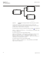
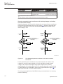
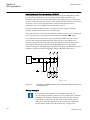
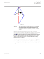
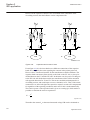
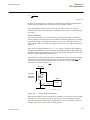
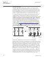
Section 3
IED application
1MRK504089-UEN C
Parallel line is out of service and earthed in both ends
Apply the same measures as in the case with a single set of setting parameters. This
means that an underreaching zone must not overreach the end of a protected circuit
for the single phase-to-earth faults. Set the values of the corresponding zone (zerosequence resistance and reactance) equal to:
2
R 0E
Xm0
æ
ö
-÷
= R 0 × ç 1 + ------------------------2
2
è
R0 + X0 ø
(Equation 153)
EQUATION561 V1 EN
2
X m0 ö
æ
X 0E = X 0 × ç 1 – ------------------------2
2÷
è
R0 + X0 ø
(Equation 154)
EQUATION562 V1 EN
Setting of reach in resistive direction
Set the resistive reach independently for each zone, for phase-to-earth loop (RIPE)
measurement.
Set separately the expected fault resistance for the phase-to-earth faults (RFPE) for
each zone. Set all remaining reach setting parameters independently of each other
for each distance zone.
The final reach in resistive direction for phase-to-earth fault loop measurement
automatically follows the values of the line-positive and zero-sequence resistance,
and at the end of the protected zone is equal to equation 155.
1
R = --- ( 2 × R1PE + R0PE ) + RFPE
3
(Equation 155)
EQUATION567 V1 EN
é
ù
ë
û
+ X0
ú
j loop = arctan êê 22××X1PE
R1PE + R0 ú
EQUATION1457 V1 EN
(Equation 156)
Setting of the resistive reach for the underreaching zone1 should follow the condition:
RFPE £ 4.5 × X 1
EQUATION569 V2 EN
(Equation 157)
Load impedance limitation, without load encroachment function
The following instructions is valid when the load encroachment function is not
activated (OperationLdCmp is set to Off). If the load encroachment function is to
be used for all or some of the measuring zones, the load limitation for those zones
according to this chapter can be omitted. Check the maximum permissible resistive
215
Application manual