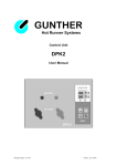
1
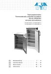
Setting Standards
Control accuracy – process data assessment
Sytem protection – flexibility – ease of use
Device Functions
Max. zones
MINI
DIALOG
MULTI
MASTER
MASTER SL
PROFESSIONAL
LC
PROFESSIONAL
1
40
36
60
72
96
180
Extendable
Sensor error detection
Load error detection
Softstart / ramp
Manual / Pulse operation
Auto-mode
Standby
°C / F switch over
Load current display
% display
Boost
Password protection
Compound heat-up
Alarm input / output
Mold memory
o
x
Diagnosis / wire test
o
x
Data recording
o
x
Start assistant
x
Performance monitoring
x
Measuring zones
x
Phase control
Group formation
x
Error logbook
x
Event logbook
x
Substitute sensor operation
x
Language selection
x
Diagram recording
x
MOLD DRIVE
HUMMEL Standard
o
x
2
Optional
Optional with PC software
o
Explanation of Device Functions
% display
Indicates the current heat output in percent;
e.g., 50 % = half output.
Group formation
Combines several heating zones for fast
parameter setting (e.g. setpoint).
°C / F switch-over
Selection of the temperature unit (Celsius or
Fahrenheit) via the Parameter menu.
Language selection
Allows language selection in the Operating and
Help menus.
Alarm input / output
Interface to machine via switching contacts;
e.g. alarm indication or standby.
Load error detection
Indicates potential errors regarding the
connected heating circuit. Reliable detection of
breakages and excess currents.
Auto-mode
If this function is activated, the average output
is used for continued heating in the event of
sensor breakage.
Max. zones
Maximum number of heating zones that can
be connected (depending on type series).
Boost
Brief setpoint increase; e.g. for removing
nozzle obstructions (jet clearing).
Mold memory
For storing all of the settings of a connected
hot-runner mold.
Compound heat-up
Uniform, controlled heat-up process in which
the fastest heating circuit waits for the slowest
circuit to catch up.
Password protection
Code for accessing the Parameter menu;
prevents unauthorized entries.
Data recording
Storage of production data; e.g. for quality
documentation purposes.
Diagnosis / wire test
Checks the connected hot-runner mold for
correct wiring and indicates errors.
Diagram recording
Records process data as diagrams; e.g. for
error analysis.
Error logbook
Recording of all process events; e.g. alarms
triggered during operation. Reliable detection
of polarity errors, breakages and short
circuiting.
Event logbook
Records user entries and process events; e.g.
alarms triggered during the manufacturing
process.
Phase control
Optional operation of the heating with adjusted
output voltage if required.
Extendable
The devices can be ordered for the currently
required zone number and then later extended
to the maximum zone number with additional
pluggable control cards.
Start assistant
The start assistant provides quick access to
production start settings.
Performance monitoring
The average heating power is detected and
monitored. An error message will appear if
there are any discrepancies caused by leaks
or heating errors.
Measuring zones
Each control area can also be defined as a
measuring zone. The tool temperature can be
displayed and monitored using a sensor on
the tool.
MOLD DRIVE
In addition to heat channel regulation the
devices can be used to control servo drives,
enabling all different kinds of movement on
the tool.
Manual / Pulse operation
Allows manual heat output setting; manual
operating mode.
Sensor error detection
Indicates potential errors regarding the connected temperature sensor.
Softstart / ramp
Reduced heating speed to dry the heating
elements.
Standby
Setpoint reduction via front button or alarm
input; e.g. if interruption/breakdown occurs.
Substitute sensor operation
Allows using the sensor of a neighboring mold
to continue the production process in the event
of sensor breakage.
3
New
From Touchsensors up to Touchpanel
TOUCH MADE BY HUMMEL
NEW
multitouch capacitive durable
4
Table of Contents
Multi-zone controllers
MULTI ................................................................................................ 8
WIRE TEST ................................................................................... 10
MULTI VIEW ................................................................................ 11
MASTER ......................................................................................... 12
MASTER SL .................................................................................. 14
PROFESSIONAL ....................................................................... 16
MOLD DRIVE .............................................................................. 18
PROFESSIONAL LC................................................................ 20
Slide-in controllers
DIALOG slide in controller ................................................ 22
Housings for slide-in controllers ..................................... 24
up to 40 zones
MINI one zone controller ................................................... 26
Built-in controller
INTEGRAL..................................................................................... 28
Accessories
Load cables ................................................................................. 30
Thermocouple cables..............................................................31
Mold connectors ........................................................................32
Single connectors ......................................................................33
Cables ..............................................................................................34
Accessories ...................................................................................35
Limited Liability
Products, design, colors and dimensions are subject to change without prior notice. We reserve the right to make technical improvements on all our products, currently ordered or for future
orders. It is the user’s responsibility to verify all dimensions and technical data. HUMMEL AG will assume no liability regarding information provided to the user by published literature or inside
technical staff, its distributors and outside sales personnel. Errors in the catalog can occur and shall not create any liability whatsoever for HUMMEL AG. All information provided by
HUMMEL AG is without guarantee and must be verified by the user.
Created & Printed by
Design and layout: intermedia marketing gmbh, Mozartstraße 2, 79183 Waldkirch, Germany, Tel. +49 (0) 76 81/ 47 78 99-0, Fax +49 (0) 76 81/ 47 78 99-27, [email protected]
Print: Druckerei Furtwängler GmbH, 79211 Denzlingen, Germany, Tel. +49 (0) 76 66 /13 31. Printed on ecologically friendly paper in May 2014.
5
Setting Standards
HUMMEL AG
6
hummel.com – your website!
Download-Center
Online Catalog
Product Pictures and Product Information
Product and Assembly Videos
Assembly and Operations Manual
Technical drawings
3D data
Certificates
Catalog and Flyer
Assembly instructions and installation instructions
Press releases
Certificates and approvals
RoHS, REACH / SVHC, WEEE, Conflict minerals
…
Enclosure-Configurator
Searching Products
Part Number search
Searching Details
Individual Enclosures
Enclosure Solutions
Online configuration, requesting and ordering
NEWS
Technology Center
Technical Information
(Protection, thread, material, …)
Diagrams and evaluation
Product description
Assembly Video and Operations Manual
News of the HUMMEL AG
Trade fairs and exhibitions
Press releases
New Products
Job vacancies
Studies, training and vocational practical training
Solutions all from one source
NEW
Touch
Cable Glands,
Circular Connectors
Solutions
Industrial Enclosures
Electronic
7
MULTI
36
+ Compact unit for 6 to 36 heating zones
+ Modular design, thus easy to maintain
Multi-zone controllers
+ With mold memory
The MULTI 6 controller series is available in
practical 6-zone steps. Its modular design with
independent slide-in controller slots ensures fast
replacement in case of malfunction.
+ Sensor monitoring and
power measurement
+ Programmable soft-start ramp
+ Process data detection
via Ethernet Interface MULTI-VIEW
o
o
Perfect ease of use and a straightforward display showing all instantaneous and setpoint
values guarantee the smooth integration of these controllers into the production processes.
The alarm indicators only light up in case of
error or malfunction. This allows to check the
operating state of the hot runner system at a
glance.
Due to the presetting of the system’s basic parameters by the factory, time-consuming configuration is not necessary – the unit is immediately ready for use. The mold memory enables
you to store the settings for all of the hot runner
molds and access these programs by a touch
of the button.
A solid metal housing with powerful cooling
fans allows continuous operation at maximum
load even under extreme operating conditions.
The rear panel features separate connectors
for the load and thermocouples, the power
switch, interface and alarm connectors.
The temperature can be increased or decreased externally by the alarm cable connecting
the controller to the control system of the machine. In case of malfunction, the controller stops
the machine immediately.
8
Setting Standards
Dimensions
Specifications
Housing
Metal enclosure, powder-coated
Available units / Order information
6-, 12-, 18-, 24-, 30 and 36-slots / TS-MULTI-6...36
Mold connection (load and TC separate)
..................................Connectors x number of poles
6-zones .......................2 x 16-poles
12-zones .....................1 x 24-poles / 1 x 32-poles (TC)
18-zones .....................2 x 24-poles / 2 x 32-poles (TC)
24-zones .....................2 x 24-poles / 2 x 32-poles (TC)
30-zones .....................3 x 24-poles / 3 x 32-poles (TC)
36-zones .....................3 x 24-poles / 3 x 32-poles (TC)
Power supply (+/- 10 %, 50 - 60 Hz)
Voltage / Connector / Connected load
400 VAC / 32 A CEKON / 22 kW
Characteristics
Power output:...............max. 16 A per zone, contactless
..................................semicconductor, zero-switching
Thermocouple: .............Fe-CuNi Type J, L or K
Control precision: .........Better 1 °C, self-optimizing
..................................(if hot runner permits)
Control range: .............50 - 500 °C (122 - 932 °F)
Operating temperature: 10 - 40 °C (50 - 104 °F)
MULTI series
13
14
15
16
17
18
7
8
9
10
11
12
1
2
3
4
5
6
Features
Alarm outputs: .............2 changeover contacts
Control inputs: .............2 switch inputs (contacts)
Data interface: ............for SUB-D plug 9-pole
Information displayed
Setpoint and instantaneous values for all zones (°C or °F),
power output in amperes or percent, alarm indicators for
temperature (over- or low temperature), current (overcurrent,
open load), TC malfunction (open, reverse)
Functions
Please open the page register of page 2 and align it on the
left side. This gives you a convenient overview of all available
functions. For function explanations, refer to page 3.
Subject to technical modifications
9
WIRE TEST
+ detects mold wiring errors
+ for MULTI 12, 24 & 36
+ prevents machine downtimes
Wire test (mold diagnosis)
The optional diagnostic function WIRE TEST is available for our
proven MULTI hot-runner controllers with 12, 24 and 36 zones.
It is extremely easy to operate via a new function button.
The connected molds are scanned and the result is directly displayed on the front panel. This function offers you increased
safety of operation, as potential faults – such as sensor polarity
reversal or mold wiring errors – are detected fully automatically.
This helps to prevent downtimes and protects your molds against
damage.
Specifications
see MULTI series page 9
Order information
TS-MULTI-12, 24, 36-WT
10
Setting Standards
MULTI View
+ for all MULTI control units
+ for mold administration and process
data transfer
+ USB or Ethernet connection
+ with PC Software for WINDOWS®
PC Interface
This interface allows you to transfer all of your mold and process
data between a MULTI controller and a PC or laptop, using
either a USB interface or an Ethernet connection.
You just need to connect the interface box to the standard data
interface of the control unit. The output of the box then provides
the required interface. Power is supplied directly via the interface
in the case of USB operation. In the Ethernet version, power is
provided by the plug-in PSU supplied.
Following installation of the MULTI-VIEW II software included in the
delivery, you can conveniently store your mold data in a PC file and,
if needed later, transfer it back to the controller again. You can use
any WINDOWS® directory of your choice for the process data.
This ensures that the data is readily available if, for example, you
wish to edit it later by PDA systems.
Specifications
Housing
Plastic shell housing
Connection
2 m controller connecting cable, RJ45 Ethernet plug or
USB plug, power supply plug for PSU
Power supply
Via USB interface or PSU supplied
Software
On CD for all common WINDOWS® versions
Order information
Ethernet:
USB:
Subject to technical modifications
TS-MULTI-VIEW-II-TCP-IP
TS-MULTI-VIEW-II-USB
11
MASTER
60
+ for 12 to 60 zones
+ extendable with pluggable control cards
+ Touch screen with brilliant display
and on-screen instructions
+ Start assistant for super fast basic setting
+ Performance monitoring for error detection
MASTER Series
Superior control precision and convenient,
straightforward touchscreen operation are
the hallmarks of the multi-zone controllers of
the MASTER series.
A help function is provided to save you the
cumbersome process of searching information in the user manual. It can be called up at
any point of the menu structure to provide
you with the specific information you need.
Apart from comprehensive system monitoring designed to protect the connected
hot-runner molds, these units offer a wire-test
diagnostic function, a tool memory and several recording or documentation options for
which the standard interfaces can be used as
well.
The devices are available in two different
sizes, either for 36 or 60 zones (housing
fully equipped in each case). The 6-zone
plug-in control cards can be inserted or
replaced from the front.
12
Setting Standards
Dimensions
Specifications
Housing
Metal housing with remote touch screen
Available units / Order information
12- to 60-zone (6-zone steps) / TS-MASTER-12…60
65
Mold connection (load and TC separate)
12 zones wired to a 24-pole load connector and a 32-pole
temperature sensor connector (HAN A)
65
MASTER 36
MASTER 60
240
240
Special configurations on request
665
300
450
665
300
410
450
410
Power supply (+/- 10 %, 50 - 60 Hz)
Voltage / Connector / Connected load
400 VAC / 32 A CEKON / 22kW
Optional:
400 VAC / 63 A CEKON / 44kW
460
Connections
660
Higher load on request
Characteristics
Power output:...............max. 16 A per zone, non-contact,
..................................switching at passage through zero
..................................with phase-angle control on request
Thermocouple: .............Fe-CuNi type J, L or K
Control precision: .........Greater than 1 °C, self-optimizing
..................................(if hot runner permits)
Control range: .............50 - 500 °C (122 - 932 °F)
Operating temperature:.10 - 40 °C (50 - 104 °F)
Features
Alarm outputs:..............2 changeover contacts
Control inputs:..............2 switch inputs (contacts)
Interfaces:....................SUB-D plug 9-pin (device)
..................................USB; Ethernet; VGA; PS2; RS232
..................................(Touch Screen)
Information displayed
12“ - SVGA-LCD with touch screen
Constantly displayed: setpoint and actual values plus power
output for all zones
Functions
Please open the page register of page 2 and align it on the
left side. This gives you a convenient overview of all available
functions. For function explanations, refer to page 3.
Subject to technical modifications
13
MASTER SL
72
+ up to 72 zones
+ flexible withdrawable unit design
+ space-saving, free-standing housing
+ Process control and diagnosis function
MASTER SL controllers
The MASTER SL control series is designed to
meet the highest demands with up to 72
control points. The devices start at 24 zones
and can be extended to 72 using the 6
withdrawable units.
The control devices are extremely accurate
and all of the functions of the MASTER series
e.g performance monitoring for leakage
detection as well as tool temperature measuring for checking mold cooling.
The 12“ touch screen with its unique colour
display allows all settings to be changed
quickly and easily. The on-screen instructions
and settings asssistant provide enhanced
user-friendliness.
The standard data interfaces enable data
transfer and, if necessary, remote diagnosis
over the Internet.
14
Setting Standards
Dimensions
MASTER SL
Specifications
Housing
Bottom cabinet: ............Metal enclosure, powder-coated;
..................................with lockable castors
Display :......................Metal enclosure, powder-coated;
..................................with touch screen interface
65
240
Available units / Order information
24- to 72-zones, in 6 zone steps / TS-MASTER-SL-24…72
300
450
955
1400
Mold connection (load and TC separate)
12-zone units wired to a 24-poles load connector
and a 32-poles TC connector
Special configurations on request
460
640
Connections
95
Power supply (+/- 10 %, 50 - 60 Hz)
Voltage / Connector / Connected load
400 VAC / 63 A CEKON / 44 kW
Characteristics
Power output:...............max. 16 A per zone, contactless
..................................semicconductor, zero-switching
Thermocouple: .............Fe-CuNi type J, L or K
Control precision: .........Better 1 °C, self-optimizing
..............................................(if hot runner permits)
Control range: .............50 - 500 °C (122 - 932 °F)
Operating temperature: 10 - 40 °C (50 - 104 °F)
Features
Alarm outputs: .............2 changeover contacts
Control inputs: .............2 switch inputs (contacts)
Interfaces:....................SUB-D plug 9-pin (device)
..................................USB; Ethernet; VGA; PS2; RS232
..................................(Touch Screen)
Operation & display
12“-SVGA-LCD with touch-screen
Permanent indication of setpoint and instantaneous
values plus power outputs for all zones
Functions
Please open the page register of page 2 and align it on the
left side. This gives you a convenient overview of all available
functions. For function explanations, refer to page 3.
15
PROFESSIONAL
180
+ For 48 to 180 zones
+ Touch-screen control panel with on-screen manual
+ Error and event log
+ Start-up wizard for rapid base setting
+ Performance control and mold temperature
measurement for advanced process control.
Professional controllers
The PROFESSIONAL controller series has
been designed for controlling multi-cavity
molds, thus satisfying the highest quality
demands. In addition, extensive diagnostic
and log functions are available that greatly
facilitate testing and starting up complex hot
runner molds.
PC-based operation with a touch-screen
panel ensures maximum operator convenience, thanks also to a clearly arranged display and optimal user guidance. If space is
scarce, the control panel can be separated
from the controller.
All parameter settings can be stored and
managed conveniently in the system’s memory, which provides extensive storage and display options.
All production process parameters (as well
as potential errors) are recorded and documented most clearly.
o
16
These controllers are available in 12-zone
steps, each dozen being wired to a 24-pole
load connector and a 32-pole sensor connector (HAN A). The modular pluggable
control cards with 16 Amp power unit allow
zones to be extended or to be quickly
swapped if an error occurs.
Setting Standards
Dimensions
PROFESSIONAL
Specifications
Housing
Bottom cabinet: ............Metal enclosure, powder-coated;
..................................with lockable castors
Display: ......................Metal enclosure,
..................................powder-coated, with touch-screen
..................................control panel
70
320
400
Available units / Order information
48- to 180-zones, in 12 zone steps /
TS-PROFESSIONAL-48...180
580
960
650
1500
Mold connection (load and TC separate)
12-zone units wired to a 24-poles load connector
and a 32-poles TC connector
Special configurations on request
500
Connections
90
Power supply (+/- 10 %, 50 - 60 Hz)
Voltage / Connector / Connected load
400 VAC / 63 A CEKON / 44 kW
Higher load on request
Characteristics
Power output:...............max. 16 A per zone, contactless
..................................semicconductor, zero-switching
Thermocouple: .............Fe-CuNi type J, L or K
Control precision: .........Better 1 °C, self-optimizing
..............................................(if hot runner permits)
Control range: .............50 - 500 °C (122 - 932 °F)
Operating temperature: 10 - 40 °C (50 - 104 °F)
Features
Alarm outputs: .............2 changeover contacts
Control inputs: .............2 switch inputs (contacts)
Interfaces:....................SUB-D plug 9-pin (device)
..................................USB; Ethernet; VGA; PS2; RS232
..................................optional WLAN (Touch Screen)
Operation & display
15“-XGA-LCD with touch-screen
Permanent indication of setpoint and instantaneous
values plus power outputs for all zones
Functions
Please open the page register of page 2 and align it on the
left side. This gives you a convenient overview of all available
functions. For function explanations, refer to page 3.
Subject to technical modifications
17
MOLD DRIVE
180
+ Temperature control for up to 48 heating zones
+ Motor control for up to four servo drives
+ Touchscreen operation with On Screen Manual
+ Monitoring of the hot-runner system and
servo drives
+ Modular, easy-to-service device construction
with plug-in cards
Hot-Runner Controller with
Motor Control System
The MOLD DRIVE device combination, consisting of a hot-runner controller and motor
control system, eliminates the need for a further peripheral device for electrically driven
functions on the tool, e.g. for unscrewing or
linear movements. In addition to problemfree operation at up to 180°C, the advantages of servomotors include utmost repeatability of motion sequences and precise
reproducibility of the end position. Modular
slide-in controller technology and the excellent control performance of the TEMP STAR
PROFESSIONAL devices complement the
positive aspects of the drive for hot-runner
temperature control.
Both functions can be operated and managed easily via the robust capacitive touchscreen. The PC used for data visualisation
and storage has various interfaces for data
transmission and remote diagnosis.
Numerous monitoring functions, e.g. for torque or hot-runner temperature limits, detect
faults or system errors and warn the operator of possible damage in good time.
18
Setting Standards
Dimensions
PROFESSIONAL
Specifications
Housing
Bottom cabinet: ............Metal enclosure, powder-coated;
..................................with lockable castors
Display: ......................Metal enclosure,
..................................powder-coated, with touch-screen
..................................control panel
70
320
400
Available devices / Order information
12 to 48 heating zones, 1 to 4 servo drives
TS-MD-12…48HZ-1…4SM
580
960
650
1500
Mold connection (load and TC separate)
12 zones each on a 24-pole load connector and a 32-pole
thermocouple (HAN-A)
Special configurations on request
500
Connections
90
Power supply (+/- 10 %, 50 - 60 Hz)
Voltage / Connector / Connected load
430 VAC / 63 A CEKON / 44 kW
Higher load on request
Characteristics
Power output:...............max. 16 A per zone, contactless
..................................semicconductor, zero-switching
Thermocouple: .............Fe-CuNi type J, L or K
Control precision: .........Better 1 °C, self-optimizing
..............................................(if hot runner permits)
Control range: .............50 - 500 °C (122 - 932 °F)
Operating temperature: 10 - 40 °C (50 - 104 °F)
Features
Alarm outputs: .............2 changeover contacts
Control inputs: .............2 switch inputs (contacts)
Interfaces:....................SUB-D plug 9-pin (device)
..................................USB; Ethernet; VGA; PS2; RS232
..................................optional WLAN (Touch Screen)
Operation, display
15" XGA LCD, capacitive touchscreen
Motor connection
Load and feedback cables via M23 connector
Motors
1 to 4 servomotors, preferably complete drives from Servomold
Subject to technical modifications
19
PROFESSIONAL LC
96
+ For 48 up to 96 zones
+ reasonably priced membrane keyboard
as a console or fixed panel
+ Rugged, user-friendly construction
+ highest level of user friendliness and
extendable process control with optional
PC software
x
x
x
x
x
x
x
x
x
x
x
x
20
Professional control unit LC
The LC series differs from the TEMP-STAR
PROFESSIONAL unit with touch screen by
employing a cost-effective production display for use in extremely demanding production environments. The rugged membrane keyboard with bright LEDs allows easy
setting of all production parameters. The unit
is equipped with an individual error indicator for each control zone.
An optional software is available for wiring
testing, starting of new molds, mold data
management or troubleshooting. This software can be installed on any PC or notebook
with Windows®, giving the user access to all
the same functions as on the touch-screen
equipped unit, however, by using a mouse
instead of a touch-screen.
A communication port on the back of the unit
allows connection of the production display
or a PC / notebook, even while the unit is
running.
In case of a malfunction, service-friendly control cards for 6 zones each can be replaced
without any tools. The units are built for 48
to 96 zones.
Setting Standards
Dimensions
Specifications
PROFESSIONAL LC
Housing
Bottom cabinet: ............Metal enclosure, powder-coated;
..................................with lockable castors
User panel: ..................Metal enclosure; powder-coated;
..................................with membrane keyboard
85
310
PROFESSIONAL LC
160
400
50
300
415
580
960
650
580
1245
960
650
Available units / Order information
48- to 96-zones, in 12 zone steps /
TS-PROFESSIONAL-48...96-LC
Mold connection (load and TC separate)
12-zone units wired to a 24-poles load connector
and a 32-poles TC connector
Special configurations on request
500
90
500
90
Power supply (+/- 10 %, 50 - 60 Hz)
Voltage / Connector / Connected load
400 VAC / 63 A CEKON / 44 kW
Higher load on request
Connections
Characteristics
Power output:...............max. 16 A per zone, contactless
..................................semicconductor, zero-switching
Thermocouple: .............Fe-CuNi type J, L or K
Control precision: .........Better 1 °C, self-optimizing
..............................................(if hot runner permits)
Control range: .............50 - 500 °C (122 - 932 °F)
Operating temperature: 10 - 40 °C (50 - 104 °F)
Features
Alarm outputs:..............2 changeover contacts
Control inputs:..............2 switch inputs (contacts)
Data interface: .............for SUB-D plug 9-pole
User panel: ..................M16 connector 10-pole
Operation, Information displayed:
Membrane keyboard with LED display for 24-zones,
scrollable. Setpoint and instantaneous values and
alarm indicators. Optional operation with a PC / Laptop.
Functions
Please open the page register of page 2 and align it on the
left side. This gives you a convenient overview of all available
functions. For function explanations, refer to page 3.
Subject to technical modifications
21
DIALOG
40
+ Flexible slide-in technology
+ 16-ampere power unit integrated
+ Replacement within seconds in
case of failure
+ Central control with memory function
+ Optimal mold protection
+ Ground leakage measurement
o
Slide-in controllers with
central control unit
The DIALOG series combines all of the
advantages of the classical, single slide-in
controller with the central handling afforded
by a multi-zone controller. Available controller housings can be equipped with just the
number of slide-in modules actually needed,
plus a central control unit if required. Unneeded slots simply remain empty and can be
refitted at any time.
The integrated 16-ampere (3.600 watt)
power unit allows fast and easy module
replacement, without the need to open the
housing or disconnect any cables!
The DIALOG central control unit fits into any
empty slot of the housing and allows central
adjustment of any number of slide-in modules. All functions can be accessed and controlled either directly by the control module
or the central control unit.
The front panel buttons guarantee easy operation. Both the instantaneous and setpoint
values are permanently displayed. In addition, the setpoint window allows to display the
instantaneous output power either in
amperes or percent.
Ground fault, temperature deviation, overcurrent and sensor error are monitored and
indicated separately for each control module. Together with the programmable soft-start
function, the DIALOG series thus provides
optimal protection for the connected hot runner system.
22
Setting Standards
Dimensions
DIALOG slide-in
Specifications
Slide-in controller & central control unit
European standard-size PCB, 160 x 100 mm
Connections
via central multipoint connector provided in housing
Power supply
230 VAC / 50 - 60 Hz
Slide-in controller characteristics
Power output:...............max. 16 A per zone, contactless
..................................semiconductor, zero-switching
Thermocouple: .............Fe-CuNi type J or L
Control precision: .........Better 1 °C, self-optimizing
..............................................(if hot runner permits)
Control range: .............50 - 500 °C (122 - 932 °F)
Operating temperature: 10 - 40 °C (50 - 104 °F)
Information displayed on slide-in controller
Setpoint and instantaneous values for all zones
(°C or °F), power output in amperes or percent, alarm indicators
for temperature (over- or low temperature), current (overcurrent,
open load), ground fault, TC malfunction (open, reverse)
Order information
TS-DIALOG-REGELEINSCHUB (Slide-in controller)
TS-DIALOG-ZENTRALE (Central unit)
Functions
Please open the page register of page 2 and align it on the
left side. This gives you a convenient overview of all available
functions. For function explanations, refer to page 3.
Subject to technical modifications
23
Housings
+ For DIALOG slide-in controllers
+ Flexibility due to modular design
+ Powerful cooling fans
+ Alarm connector
Housings for slide-in controllers
+ Data interface
The stylish and robust metal housing can be
fitted with withdrawable units from the
DIALOG series and central control unit if
desired.
The slots can be filled with any number of
controller modules. Unused slots have to be
covered with a cover plate and can be refitted later if necessary. Thus, the user gets a
highly flexible system that can be adapted
perfectly to individual requirements.
As all controllers come with integrated
power units, replacing modules or adding
new ones is just a matter of seconds, without
the need to open the housing or disconnect
any cables! This minimizes down time in
case of malfunction.
The rear panel features separate connectors
for the load and the thermocouples, the
alarm and interface connectors, and the
load circuit fuses.
The temperature can be decreased externally by the alarm cable connecting the controller to the control system of the machine.
In case of malfunction, the controller stops
the machine immediately. The standard data
interface can be used for remote control or
logging tasks.
24
Setting Standards
Dimensions
22-fach
2-slots
zones
Specifications
6-fach
6-slots
390
Housing
Metal enclosure, powder-coated
390
200
200
175
Available sizes / Order information
2-, 6-, 10-, 16-, 24-, 32- and 40-slots /
TS-REGLERGEHAEUSE-2...40-FACH
350
10-slots
10-fach
390
Mold connection (load and TC separate)
..................................Connectors x number of poles
2-slots .........................2 x 4-poles
6-slots .........................2 x 16-poles
10-slots .......................1 x 24-poles / 1 x 32-poles
16-slots .......................4 x 16-poles
24-slots .......................2 x 24-poles / 2 x 32-poles
32-slots .......................3 x 24-poles / 3 x 32-poles
40-slots .......................4 x 24-poles / 4 x 32-poles
200
550
24-slots
24-fach
16-slots
390
(TC)
(TC)
(TC)
(TC)
Special configurations on request
460
Power supply (+/- 10 %, 50 - 60 Hz)
Voltage / Connector / Connected load
2-slots: ........................400 VAC / 16 A CEKON / 11 kW
Others:........................400 VAC / 32 A CEKON / 22 kW
330
460
32-slots
32-fach
460
390
40-slots
40-fach
Higher loads on request
390
Load circuit fuses
16 ampere FF
located on rear panel
Cooling fans
Cooling fans
590
460
590
550
Housing sizes...............Number of fans
2-slots .....................................1
6-slots .....................................2
10-, 16-, 24-, 32-, 40-slots ........3
Alarm connector
Circular plug 12-pole,
1 alarm output / max. 33 V - 0,5 A
1 „Standby“ switch input (contact)
for alarm cables, see „Accessories“
Interface connector
SUB-D, 15-pole, female
Subject to technical modifications
25
MINI
1
+ For 1 zone, 10 amp max.
+ Cost-effective compact unit
+ Mains connector with protective earth
+ Fully functional hot runner monitoring
Basic control unit
This compact unit is designed to provide temperature control of a load circuit. It is suitable for load currents up to 10 A. The control
unit is powered through a 230 VAC mains
plug with protective earth.
The unit is operated via buttons on the front
panel, where the instantaneous and setpoint
values are constantly displayed. The display
for the setpoint can also be used to indicate
the output power in either amperes or percent. Manual operation, standby and boost
functions can be directly accessed via front
panel buttons.
For highest possible protection of the hot runner, all possible malfunctions, like ground
fault, temperature deviations, overcurrent
and sensor breakage are constantly monitored and instantly indicated. Additional protection is provided by the programmable
soft-start function.
The back side of the rugged metal housing
holds two 4-pole connectors for load and
thermocouple, the load circuit fuse and the
unit's main switch.
26
Setting Standards
Dimensions
Specifications
Housing
Metal enclosure, powder-coated
Mold connection (load and TC separate)
2 x 4-poles
Power supply (+/- 10 %, 50 - 60 Hz)
230 VAC / SCHUKO connector / 2,3 kW
Characteristics
Power output:...............max. 10 A per zone, contactless
..................................semicconductor, zero-switching
Thermocouple: .............Fe-CuNi type J or L
Control precision: .........Better 1 °C, self-optimizing
..............................................(if hot runner permits)
Control range: .............50 - 500 °C (122 - 932 °F)
Operating temperature: 10 - 40 °C (50 - 104 °F)
Operation
Membrane keyboard with LED display at the front
Information displayed
Setpoint and instantaneous values (°C or °F), power
Output in amperes or percent, alarm indicators for
temperature (over- or low temperature), current
(overcurrent, open load), ground fault, TC malfunction
(open, reverse)
Order information
TS-REGELGERÄT-1-FACH
Functions
Please open the page register of page 2 and align it on the
left side. This gives you a convenient overview of all available
functions. For function explanations, refer to page 3.
Subject to technical modifications
27
INTEGRAL
+ Add-on for machines
+ Modular for 6 - 48 controller circuits
+ Slide-in controller boards
+ Operation via machine
Built-in temperature controllers
The INTEGRAL temperature controllers were
developed for machine installation. Thanks
to the slide-in controller boards for 6 controller circuits each, a very flexible system can
be obtained. The controllers are preferably
recommended for hot runner applications,
but may also be used for other applications.
The empty 19“ rack for up to 48 controller
circuits is ideally suited as a basic machine
version with a good price / performance
ratio. The controller can be later adapted
according to requirements. The slide-in controller boards can be added or exchanged
within shortest time without any tools.
Screw terminals with labels ar provided for
connection of load circuits and temperature
sensor.
A CAN interface is provided for operation.
In addition to the existing PC user interface,
the system can be adapted to work with
other existing machine programs.
28
Setting Standards
Dimensions
Specifications
INTEGRAL
Rack
19“ rack; 84 TE, 7 HE for max. 48 zones
370
Available unit sizes
6 to 48 slots in increments of 6
310
482
Connections
Screw terminals for power supply, load circuits and thermocouples
12 pole alarm plug
Data bus SUB-D 9 pole (connector for control unit)
Power supply
Voltage / current / power requirements
400 VAC +/- 10% / 3 x 63 A / 44 kW
Connections
Specifications
Power output:...............max. 16 A per zone, contactless zero..................................voltage switching
Thermonal sensor: ........Fe-CuNi Type J or L
Accuracy: ....................better than 1 °C, self optimizing
(with appropriate hot runner version)
Control range: .............50 - 500 °C
Operational temperature: 10 - 40 °C
(Cooling fans must be provided
in rack for full output power)
Operating, indicators
With TEMP-STAR Professional Software, Professional membrane
keyboard or customization for existing operational components
Subject to technical modifications
29
ACCESSORIES
Load cables
+ Tested cables, length 5 m
+ Connection acc. to DIN 16765 – A
Controller-to-mold connection cables
Connects the hot runner safely to the controller.
Heat-resistant PVC cables, ready for use, complete with high-quality, heavy-duty industrial connectors.
Available either complete (with plugs) and tested, or with open
cable ends for customized connection.
Design
Controller side: straight cable outlet
Mold side: lateral cable outlet
Order information
Load cable complete
TS-LK-4-POL, 4-poles, length 5 m
TS-LK-10-POL, 10-poles, length 5 m
TS-LK-16-POL, 16-poles, length 5 m
TS-LK-24-POL, 24-poles, length 5 m
for a max. of
2 zones
5 zones
8 zones
12 zones
Load cable, ends open
TS-LK-4-POL-OE, 4-poles, length 5 m
TS-LK-10-POL-OE, 10-poles, length 5 m
TS-LK-16-POL-OE, 16-poles, length 5 m
TS-LK-24-POL-OE, 24-poles, length 5 m
(Special lengths and configurations on request)
30
2 zones
5 zones
8 zones
12 zones
Setting Standards
Thermocouple cables
• Compensation cables, FeCuNi
(for thermocouples type J and L)
Controller-to-mold connection cables
• Connection acc. to DIN 16765 – A
Heat-resistant compensating lines, ready for use,
complete with high-quality, heavy-duty industrial
plugs (type HAN-A).
Connects the hot runner safely to the controller.
Available either complete (with connectors) and tested,
or with open cable ends for customized connection.
Design
Controller side: straight cable outlet
Mold side: lateral cable outlet
Order information
TC cables complete
TS-TFK-4-POL, 4-poles, length 5 m
TS-TFK-10-POL-HAN-A
10-poles, length 5 m
TS-TFK-16-POL-HAN-A
16-poles, length 5 m
TS-TFK-24-POL-HAN-A32
24-poles, length 5 m, connector 32-poles
for a max. of
2 zones
5 zones
8 zones
12 zones
TC cables, ends open
TS-TFK-4-POL-OE, 4-poles, length 5 m
TS-TFK-10-POL-HAN-A-OE
10-poles, length 5 m
TS-TFK-16-POL-HAN-A-OE
16-poles, length 5 m
TS-TFK-24-POL-HAN-A32-OE
24-poles, length 5 m, connector 32-poles
2 zones
5 zones
8 zones
12 zones
(Special lengths and configurations on request)
31
ACCESSORIES
Mold connectors
+ For load or sensor, or both combined
+ For connection acc. to
DIN 16765 – A + B
Mold connectors
These high-quality industrial connectors are suitable to be fitted
to injection molds.
We offer connectors for separate load and sensor wiring as well
as for combined wiring.
Order information
Load connectors (max. contact load 16 A)
„Load“ mold connector
4-poles, male insert, fixing clamp 1x
TS-WLS-4-POL
10-poles, male insert, fixing clamp 1x
TS-WLS-10-POL
16-poles, male insert, fixing clamp 1x
TS-WLS-16-POL
24-poles, male insert, fixing clamp 1x
TS-WLS-24-POL
Thermocouple connectors (HAN A)
„TC“ mold connector
4-poles, female insert, fixing clamp 1x
TS-WTFS-4-POL
10-poles, female insert, fixing clamp 1x
TS-WTFS-10-POL-HAN-A
16-poles, female insert, fixing clamp 1x
TS-WTFS-16-POL-HAN-A
32-poles, female insert, fixing clamp 2x
TS-WTFS-32-POL-HAN-A
Combination connectors (max. contact load 16 A)
„Load / TC“ mold connector
4-poles, male insert, fixing clamp 1x
TS-WLTFS-4-POL
8-poles, male insert, fixing clamp 2x
TS-WLTFS-8-POL............
16-poles, male insert, fixing clamp 2x
TS-WLTFS-16-POL..........
24-poles, male insert, fixing clamp 2x
TS-WLTFS-24-POL
32
for a max. of
2 zones
5 zones
8 zones
12 zones
2 zones
5 zones
8 zones
16 zones
1 zones
2 zones
4 zones
6 zones
Setting Standards
Single connectors
• Male or female contacts
• Cable outlet straigth or lateral
Single connectors
These high-quality industrial connectors are suitable for assembling customized connecting cables.
The connector housings are available with socket or pin contacts,
and with a straight or lateral cable outlet.
Order information
Load connectors (max. contact load 16 A)
for a max. of
Male or female insert, Cable outlet straigth or lateral
4-poles, fixing clamp 1x
2 zones
TS-LS-4-POL
10-poles, fixing clamp 1x
5 zones
TS-LS-10-POL
16-poles, fixing clamp 1x
8 zones
TS-LS-16-POL
24-poles, fixing clamp 1x
12 zones
TS-LS-16-POL
Thermocouple connectors (HAN A)
Male or female insert, Cable outlet straigth or lateral
4-poles, fixing clamp 1x
2 zones
TS-TFS-4-POL
10-poles, fixing clamp 1x
5 zones
TS-TFS-10-POL-HAN-A
16-poles, fixing clamp 1x
8 zones
TS-TFS-16-POL-HAN-A
32-poles, fixing clamp 2x
16 zones
TS-TFS-32-POL-HAN-A
Combination connectors (max. 16 A Load and TC combined),
Male or female insert, Cable outlet straigth or lateral
4-poles, fixing clamp 1x
1 zone
TS-LTFS-4-POL
8-poles, fixing clamp 2x
2 zones
TS-LTFS-8-POL
16-poles, fixing clamp 2x
4 zones
TS-LTFS-16-POL
24-poles, fixing clamp 2x
6 zones
TS-LTFS-24-POL
33
ACCESSORIES
Cables
+ Compensation cables, FeCuNi
(for thermocouples type J and L)
+ Load cables (max. 16 A)
+ Combination cables for load & TC
(for thermocouples type J and L)
Cableware sold by the meter
These types of cable are suitable for assembling customized connecting cables.
Depending on the type of wiring, different cable options are available, allowing you to connect the load and thermocouples either separately (acc. to DIN 16765 – A) or by way of a combination cable (acc. to DIN 16765 – B).
Order information
Compensation cables for TC type J or L (black)
4-cores, coiled
TS-MWTFK-4
10-cores, coiled
TS-MWTFK-10
16-cores, coiled
TS-MWTFK-16
24-cores, coiled
TS-MWTFK-24
Load cables for loads up to 16 A (grey)
4-cores + ground, coiled
TS-MWLK-4
10-cores + ground, coiled
TS-MWLK-10
16-cores + ground, coiled
TS-MWLK-16
24-cores + ground, Zcoiled
TS-MWLK-24
Load / TC combination cables type J or L (red)
4-cores, 2x TC, 2x load up to 16 A
+ ground, coiled
TS-MWLTFK-4
8-cores, 4x TC, 4x load up to 16 A
+ ground, coiled
TS-MWLTFK-8
16-cores, 8x TC, 8x load up to 16 A
+ ground, coiled
TS-MWLTFK-16
24-cores, 12x TC, 12x load up to 16 A
+ ground, coiled
TS-MWLTFK-24
34
for a max.of
2 zones
5 zones
8 zones
12 zones
2 zones
5 zones
8 zones
12 zones
1 zones
2 zones
4 zones
6 zones
Setting Standards
Accessories
Spare parts / genuine accessories
Genuine spare parts will be available for at least 10 years from
the date of purchase for all TEMP-STAR controllers.
The use of genuine accessories ensures perfect operation and
complete guarantee during the term of warranty.
Accessories
•
•
Cover plate for unused controller housing slots
TS-BP-3HE-10TE
Alarm cable for all TempStar
controllers (12-poles connectors)
TS-ALARMKABEL-12-POL
Selection of spare parts
• Load-circuit fuses, 16 A FF,
for all TEMP-STAR controllers
TS-LS-16-A-FF
• Cooling fan, 230 VAC,
for all TEMP-STAR controllers
TS-KL120
• Spare filters for cooling fans (10-piece set)
TS-EF120
• Controller card MULTI 6,
BG-MULTI6-BE1
• Control card for MASTER / PROFESSIONAL
TS-MASTER-CB
35
HUMMEL Divisions
Electro Technology
Touchpanels – Solutions – Custom fabrication of Enclosures
Industrial Enclosures – Cable Glands – Cable Protection – Circular Connectors
Electronic
Operator Panels – Frontsheets and Keyboards – Battery Chargers
Cable Assembly – Sensors – Controls – Systems Solutions – Temperature Controllers
Heating Equipment
Solar Heating – Valves and Fittings – Compression Fittings
Heat Pumps – Thermostatic Heads
Customised
Parts made of Metal and Nylon
HUMMEL AG
Division EL
Lise-Meitner-Straße 2
79211 Denzlingen
Germany
Tel.
Fax
E-Mail
+49 (0)76 66 /9 11 10-0
+49 (0)76 66 /9 11 10-97 99
[email protected]
HUMMEL AG
Lise-Meitner-Straße 2
79211 Denzlingen
Germany
www.hummel.com
intermedia 0614
www.hummel.com