1
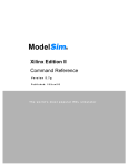
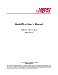
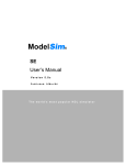
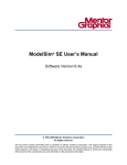
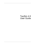
CONTENTS
VHDL: ONE LANGUAGE
IS NOT ENOUGH
Only a few years ago, the great language
war between VHDL and Verilog was raging.
Many industry experts said one language
would win over the other and that’s what the
design community would use.
Yes, there has been a winner — and it’s
both languages.
As a result, the Hardware Description
Language market continues to grow. VHDL
usage remains strong for a number of
reasons. This article focuses on two: VHDL’s
history and its functionality.
BECOMING A STANDARD
VHDL was first intended as a Hardware
Description Language for documenting
designs. It originated from a US
Government/DOD-sponsored effort to overhaul the way integrated circuits were
exchanged between companies. In 1987, the
IEEE adopted VHDL as a standard and
many EDA companies began developing
tools supporting the language.
VHDL is widely used today. The biggest
user communities are Europe and the FPGA
markets. Europe always looks for standards
when adopting methodologies — and at the
time, Verilog was owned by Cadence and not
a standard. Conversely, the FPGA vendors
had formed an alliance with EDA vendors
who only developed VHDL tools.
1
VHDL: ONE
L A N G UAG E I S
N OT E N O U G H
ModelSim capitalizes on
the strengths of VHDL
and Verilog to bring you
the best simulator on the
market
2
D E BU G
DETECTIVE
Introducing Debug
Detective: Advanced
debug and analysis
for ModelSim
3
M A RC O N I
ModelSim streamlines
distributed system
simulation environment
development
6
7
FAQ s
Getting the most out
of ModelSim
8
HDL DESIGN
AND TRAINING
SCHEDULE
DESIGN DISCIPLINE
VHDL is able to balance its flexibility and
power by enforcing a certain degree of discipline on the designer. Strictly enforced type
and other rules define how and when statements can be used. While these rules may
appear cumbersome at first, their value in
complex designs rapidly overshadows any
aspect of the language that could obstruct the
design process.
Unlike languages such as Verilog, it is not
possible in VHDL to compile code then spend
hours discovering that your problem is a range
or not assigning enough bits to a vector.
VHDL is excellent at the higher levels of
abstraction — Register Transfer and behavioral. It includes features such as enumerated
types, permitting the designer to model
without worrying about implementation and
allowing synthesis tools to choose the best
encoding schemes.
POWERFUL FEATURE SET
VHDL is highly organized, making use of
libraries to store units and allowing connectivity of design units to be controlled by
configurations. It has generated functionality
that permits units to be replicated easily within
loops. You only have to look at the new
Verilog 2001 specifications to see an endorsement of long-standing VHDL language
TIPS AND TRICKS
Expert answers about
ModelSim and the
simulation process
F RO M C O N C E P T
TO S I L I C O N
Advanced techniques for
complex FPGA design
C O N TA C T
C O N T I N U E D O N PA G E 5
Model Technology, Inc.
10450 S.W. Nimbus Avenue, Bldg. R-B
Portland, OR 97223
Phone
503-641-1340
Email
[email protected], [email protected],
[email protected]
Web
www.model.com
A publication of Model Technology Incorporated
Q3 01
MODELUSER
2
MODELUSER Q3 01
Debug Detective™, a new product in the
HDL Designer Series family of tools,
provides extended debug and design
analysis capabilities to the ModelSim® PE
and SE simulators. This tool was developed
specifically as a natural extension to your
ModelSim user interface by adding visualization and unique interactive debugging
features.
Debug Detective snaps on to your
ModelSim installation. When you are ready
to use the debug features, they are available
via toolbar buttons, pull-down menus or by
double-clicking on the region in the
Structure window.
By referencing the source code displayed
in ModelSim’s Source window, Debug
Detective renders on-the-fly graphical and
tabular views of any level of your design
hierarchy. These renderings are completed
INTRODUCING DEBUG DETECTIVE,
A D VA N C E D D E B U G A N D A N A LY S I S
FOR MODELSIM
Debug Detective renders views of any and all levels of the design into block, Interface-Based Design,
state, or flow chart diagrams.
rapidly and without any change to the
source code or need for a special database.
You can use Debug Detective without any
change to your current ModelSim simula-
Interface-Based Design view of a structural HDL netlist.
tion environment — even your invoke
scripts are not affected.
Debug Detective produces graphical or
tabular representations for any level of your
design hierarchy in the Structure window or
any section of code displayed in any other
ModelSim debug window.
The rendered graphical views include
state machine diagrams for control logic,
flow charts for sequential logic such as testbenches, and block diagrams for structural
netlists.
In addition to the block diagram view
for VHDL and Verilog netlists, the
Interface-Based Design™ (IBD™) view can
also be rendered. IBD is patent-pending
technology from Mentor Graphics and
offers a unique image of the netlist. The
representation uses a spreadsheet approach
to display blocks (columns), signals (rows),
and their interconnections.
C O N T I N U E D O N PA G E 4
MARCONI DEVELOPS DISTRIBUTED
S Y S T E M S I M U L AT I O N
ENVIRONMENT
Q3 01 MODELUSER
Marconi Networks employed ModelSim in its Distributed
System Simulation environment to verify C diagnostics on its
entire system chassis. Using ModelSim in the distributed CPU
environment also provided unprecedented system-level quality
assurance of the 272 ASIC system prior to tape out.
Marconi Networks — with 55,000
employees in 100 countries — provides key
technologies, equipment, and services for
the Internet, enterprise networks, and
telecommunications systems.
Jay Adams, manager of ASIC design at
Marconi, was faced with verifying a
complete system while maintaining an
aggressive product delivery date. He realized
that simulation of this magnitude could be
accomplished with ModelSim running on
hardware with 64-bit operating system
support.
“In order to achieve the speed needed to
make this massive system simulation effective, we needed to explore radical new simulation methods,” explains Adams.
Marconi already had a significant investment in testbench technology, with the testbench linked into ModelSim with the
Foreign Language Interface (FLI) C-interface. The self-checking test cases also had
embedded UNIX®-like scripting built into
them. The sophisticated testbench technology ran together with ModelSim in a
single threaded application on a single CPU.
C A P I TA L I Z I N G O N C O M P U T E
POWER
The project’s main goal was to achieve
the highest quality product while manufacturing it on time. For both hardware and
software developers to accomplish their
goals, the entire system had to be simulated.
Adams wanted to utilize the computing
power of Marconi’s substantial compute
farm. This required Marconi to solve the
problem of linking and synchronizing
Marconi partitioned their simulation on 15 separate CPUs. Communication was handled by the RPC server.
This implementation enabled software developers to verify diagnostics on the entire system.
separate Modelsim simulations running on
the farm.
To realize that goal, Tim Noh, manager
of verification, and Mark Pleso, a lead engineer, saw the use of Remote Procedure Calls
(RPC) with a client-server model as the
logical next step in the development of
Marconi’s verification environment.
Since the Marconi team was already
familiar with ModelSim’s FLI C interface,
the design of the RPC server-client was
made much easier. The testbench, system
diagnostics and 272 ASICs with embedded
memory would communicate through RPC.
The RPC libraries allow C language
programs to make procedure calls with
other CPUs on a network. This is accomplished with a server and client, with each
client running on its own CPU. The client
sends a request to a server, the server
C O N T I N U E D O N PA G E 4
3
4
MODELUSER Q3 01
D E BU G D E T E C T I V E ,
C O N T I N U E D F R O M PA G E 2
All of these graphical and tabular
views speed design understanding, plus
enable advanced debugging techniques.
Via simulation toolbars on each diagram,
you can advance and step simulation time,
set breakpoints on state machines and
flow charts, add signals to the Wave and
List windows, and place probes on your
block diagram. Probes function just like
the ModelSim examine command.
Debug Detective offers animation and
cause analysis for additional debug
productivity. Animation visually displays
the flow of logic in your state diagrams
and flow charts. Color changes help you
easily trace the path of logic, visually
highlighting branches and missed states.
VCR-style buttons control your steps
through the diagram. Cause analysis
works with the ModelSim Wave window
to link a specific signal transition event
back to the source in a rendered diagram
and line in the ModelSim Source window.
For a free 30-day evaluation license
of Debug Detective, please visit
www.debugdetective.com or email
[email protected].
Visit
w w w. m o d e l . c o m
for frequent updates,
including
Application Notes
Product Highlights
and
Tips and Tricks
M A R C O N I , C O N T I N U E D F R O M PA G E 3
“ModelSim is available on all the platforms we used, including Linux®,” explains
Noh. “Because of many factors, the 15node parallel simulation environment
currently runs on Linux-based hardware.
High CPU frequencies and lower cost make
a very strong argument for this platform.
“ModelSim’s ability to compile the
design on our platform of choice —then to
E XC E E D I N G E X P E C TAT I O N S
use the compiled HDL image on other
With 15 separate CPUs running simulta- hardware architectures — made implementation of a multineous ModelSim simuarchitecture verilations, Marconi was
fication
able to demonstrate a
environment a
working BXR™-48000
cost-versus— a non-blocking
“During the distributed
performance
480 Gbps Multiservice
environment development,
decision.” he says.
Switch Router — to
“Parallel
diagnostic engineers
I could not have been more
simulation is not
and system software
the only mode of
developers.
pleased with the
verification,”
“Our expectations
performance of ModelSim
Noh adds.
of throughput were
“There is a signifexceeded. We were
and the responsiveness of
icant need to
impressed by the
share the
throughput of this
the Mentor team.”
compute
implementation,” says
resources for
Noh. “Each CPU load
Jay Adams
normal, single
was about 25 percent.
Marconi Networks
CPU batch and
For this large of a
interactive simunetwork of chips, we
lation runs as
were very happy.
well.”
“One of the most
interesting aspects of
E N A B L E S B E S T C O S T- P E R this project was the increased communicaS I M U L AT I O N
tion between the two disciplines,” Noh
ModelSim’s high-performance VHDL
adds. “The software and hardware engisimulation
and robust Foreign Language
neers were making discoveries soon
Interface (FLI) enabled Marconi to use
enough to affect the quality of the system
UNIX Remote Procedure Calls (RPC) to
for less cost.”
implement its Distributed System
M U LT I - P L AT F O R M M O D E L S I M
Simulation environment.
D R I V E S LO W C O S T P E R
ModelSim’s unique platform independS I M U L AT I O N
ence also made it possible to implement the
Because of existing testbench tech15-CPU Distributed System Simulation
nology, the decision to keep the simulation
environment on low-cost, high-performance
environment based in UNIX was simple.
hardware so Marconi could run valuable
Deciding which hardware to use was more
verification with the best cost-per-simulachallenging.
tion cycle.
processes the request appropriately and
sends back a response to the client. A separate client was set up for the testbench and
C interface to System Diagnostics, and for
the VHDL design. Each part of the VHDL
RTL design was partitioned to a separate
client/CPU with an FLI interface.
VHDL,
Q3 01 MODELUSER
CONTINUED
C O N T I N U E D F R O M PA G E 1
features. The new Verilog 2001 specification
includes VHDL-like functionality, such as
generate statements and use of libraries, to
name just a few.
Since the first release of VHDL in 1987,
other standards have come along to complement the main standard and allow EDA
vendors to accelerate their tools.
In the early days, there was no standard
method of implementing arithmetic functions or wire types and each tool had its
own library. This presented two problems.
First, the functions were not accelerated
and therefore raw code had to be executed,
causing performance problems. And
second, it was difficult to share code
between different tools. Standards such as
std logic 1164 — as well as arithmetic and
numeric standards — have allowed
EDA companies to fully accelerate
their tools and enable code to be
shared by multiple tools. ModelSim
fully accelerates all the standards using
its native compiled code architecture.
allows you to compile once and run on any
hardware platform.
All versions of ModelSim — including
OEM versions — are compliant with the
IEEE 1076.4 VITAL ASIC Modeling
Specification. In addition, ModelSim PE and
SE both accelerate the VITAL_Timing and
VITAL_Primitives packages. The procedures
in these packages are hand-optimized and
built into the simulator kernel. They are functionally equivalent to the IEEE 1076.4
VITAL ASIC Modeling Specification
(VITAL v3.0).
An extra level of optimization occurs in the
SE product — a built-in compliance checker in
ModelSim’s VHDL compiler. To qualify for
global acceleration, architecture must be
VITAL Level 1 compliant. This check is
performed automatically on all entities with
GATE-LEVEL ATTENTION
Another area where much work has
been done in VHDL is at the gate level.
This was again necessary because there
was no standard way to model gatelevel libraries and therefore no way the
modeling could be accelerated by the simulators. VITAL (VHDL Initiative Towards
ASIC Libraries) was the first specification to
define a standard way to model at the gate
level. A simulator is VITAL-compliant if it
implements the SDF mapping and if it
correctly simulates designs using the VITAL
packages, as outlined in the VITAL Model
Development Specification.
PLATFORM INDEPENDENCE
ModelSim was the industry’s first native
compiled simulator. ModelSim provides the
high-performance benefits of platformspecific native code, plus the unique advantage of platform-neutral compile. ModelSim
compiles to a platform-neutral pseudo-RISC
code. When you load your design, ModelSim
generates native code for the architecture you
used to invoke it. ModelSim’s architecture
the VITAL_Level 0 attribute set and all
architectures with the VITAL_Level 0 or
VITAL_Level 1 attribute set. If the model is
compliant, the complete model is transformed
into a state machine that does the equivalent
behavior more efficiently. The multiple VITAL
primitives become a single model, which can
have a significant effect on the simulation
performance.
VERILOG EFFICIENCIES
Even with this acceleration, using Verilog
at the gate level often is more efficient with
respect to performance and memory utilization. This is because the Verilog language was
built to model at the gate level, whereas
VHDL had to be pushed in that direction.
This is why many ModelSim users use the
seamless mixed-language facility within the
tool — they are able to carry on designing at
the RTL and behavioral levels with the
advantages of VHDL, then, for gate-level
modeling, can instantiate a Verilog netlist.
The benefits of using Verilog at the gate
level include more complete ASIC foundry
and backend tool support, plus it allows
ModelSim to handle much larger designs at a
higher performance level.
MODELSIM SUPERIORITY
ModelSim has the highest capability of
any simulator on the market. Its 64-bit
version currently runs on both Solaris and
HP, allowing customers to build processes
larger than the 32-bit limit of 4 Gb. The
recently released ModelSim version 5.5
includes Verilog gate-level optimizations,
providing up to 4X faster simulations and up
to 3X smaller memory images.
One customer using Verilog gate-level
optimizations saw a 6.5 Gb image reduced to
1.9 Gb. That reduction allowed the
customer to take a 6.5 million-gate
design and switch back to the 32-bit
version of ModelSim, eliminating the
need to use more expensive workstations. The performance of this simulation also improved 2.5X.
ModelSim handles large designs
within 32-bit workstations, preserving
customers’ significant investment in
hardware. Having 64-bit support
increases ModelSim’s capacity beyond
any other simulator on the market.
MEETING YOUR PREFERENCES
ModelSim has accommodated your
simulation language preferences — mixedHDL, HW platform and OS neutral, or
native code simulation — since 1995.
Performance and functionality should be
independent of your HDL because your
initial HDL choice most likely will not be
your last.
With integrated tools like Code Coverage,
Waveform Compare, advanced bug tracing,
ModelSim is your choice for simulation.
Today, ModelSim has 60 percent market
share in VHDL, is the industry leader in
mixed-language, and is the fastest growing
Verilog simulator on the market. That’s why
there are more than 60 active partnerships
with companies providing additional value to
ModelSim and why ModelSim is synonymous with innovation, industry leading
technology and superior support.
5
6
MODELUSER Q3 01
FAQS
The waveform compare tool can
perform comparisons based on a reference signal’s transition. This is commonly
known as a “clocked compare.” This reference
clock often is a clock, but it could also be any
signal such as a data strobe or read enable.
Q
1.) Define a virtual type that contains the
states virtual type:
A
3.) Display the translated value add wave
myConvertedSignal
Following is an example of a clocked
compare. The two datasets min and
typ are opened, and a limit of 1000 errors
set. All signals are compared with the
command compare region — recursive —
all. In addition, there are two data comparisons related to the clock. Both are done
relative to the rising edge of the
tst_pseudo.clock signal (compare clock
–rising label). The second reference clock
label clocked_delay4 is offset by 4ns. So, the
data is compared 4ns after the rising edge
of the clock. If you changed this to –4ns,
data would be compared 4ns before the
rising edge of the clock. Both examples of
the clocked compare check the
tst_pseudo.data, but with a different clock
label (–clock clock_rising and –clock
clock_delay4):
dataset open min.wlf min
dataset open typ.wlf typ
compare open -maxtotal 1000 min typ
compare region -recursive -all
compare signal min:.tst_pseudo.clock typ:.tst_pseudo.clock
# compare with clock
compare clock -rising clock_rising min:.tst_pseudo.clock
compare signal -clock clock_rising -label clocked_data
min:.tst_pseudo.data \
typ:.tst_pseudo.data
# compare with clock delay
compare clock -rising -delay {4 ns} clock_delay4 min:.tst_pseudo.clock
compare signal -clock clock_delay4 -label clocked_delay4_data
min:.tst_pseudo.data \
typ:.tst_pseudo.data
compare info -write compare_info.txt
compare start
Q
A
How do I convert signal values to
strings?
You may want to display certain signal
values as strings. For example, rather
than displaying the value 0, you may want
to display the string idle. The virtual type
command allows you to do this.
The virtual type command creates a new
enumerated type, known only by the GUI.
The steps for using the command are:
{ state0 state1 state2 state3} myState
2.) Define a virtual function for translating
the signal values to strings virtual function:
{(mystate)mysignal} myConvertedSignal
When myConvertedSignal is displayed in
the Wave, List or Signals window, the
string state0 will appear when mysignal ==
0, state1 when mysignal == 1, state2 when
mysignal == 2, etc.
See the virtual type function in the ModelSim
Command Reference for further details.
Q
A
How do I sample signals at a clock
change?
You can do this easily by adding
signals to the list window using the
–notrigger argument. –notrigger disables
triggering the display on the specified
signals. For example:
add list clk –notrigger a b c
When you run the simulation, list window
entries for clk, a, b, and c appear only
when clk changes. If you want to display
on rising edges only, you have two options:
1.) Turn off the list window triggering on
the clock signal, then define a repeating
strobe for the list window.
2.) Define a “gating expression” for the list
window that requires the clock to be in
a specified state.
See the add list command in the ModelSim
Command Reference for further details.
Q
A
I’m seeing different simulation results
from ModelSim and another Verilog
simulator. Why is this happening?
This may happen as a result of simultaneous events being executed in a
different order. The Verilog language does
not require simulators to execute simultaneous events in a particular order.
Unfortunately, some models are inadvertently written to rely on a particular event
order. These models may behave differently when ported to another Verilog simulator. A model with event order dependencies is ambiguous and should be corrected.
For example, the following code is
ambiguous:
module top;
reg r;
initial r = 0;initial r = 1;
initial #10 $display(r);
endmodule
The value displayed for r depends on the
order that the simulator executes the initial
constructs that assign to r. Conceptually,
the initial constructs run concurrently and
the simulator is allowed to execute them in
any order. ModelSim Verilog executes the
initial constructs in the order they appear
in the module, and the value displayed for
r is 1. Verilog-XL produces the same
result, but a simulator that displays 0 has
also produced correct results.
Since many models have been developed on
Verilog-XL, ModelSim Verilog duplicates
Verilog-XL event ordering as much as
possible to ease the porting of those
models to ModelSim Verilog. However,
ModelSim Verilog does not match VerilogXL event ordering in all cases, and, if a
model ported to ModelSim Verilog does
not behave as expected, you should suspect
that there are event order dependencies.
See “Event order issues” in the Verilog
chapter of the ModelSim User’s Manual
for further details.
Q
A
How do I hide library cell signals
when saving a waveform file?
Gate-level simulations may result in
large waveform files because the internal
signals of your library cells are saved. The
following method will prevent these signals
from being saved in a Verilog design.
If your cells are enclosed in Verilog `celldefine and `endcelldefine preprocessor directives, you can specify –fast on the vlog
command line when compiling the cell
library. This will basically hide the innards
of the cells and hence the internal signals
will not be saved. A further benefit of this
methodology is that the cells compiled
with –fast will consume less memory.
See the “Verilog” chapter in the ModelSim
User’s Manual for further details on –fast.
Q3 01 MODELUSER
TIPS AND TRICKS
ModelSim 5.6 SE release includes two new
command options that provide Simulation
statistics. The Verilog (vlog) and VHDL
(vcom) compilers include the –time.
ModelSim (vsim) now supports the
command simstats.
The –time option will report the cumulative wall clock time needed to compile your
netlists. The following example reports the
cpu time required to compile the Verilog
code in the mixed-HDL design in the examples directory. The same format can be used
for VHDL (vcom –time *.vhd).
vlog –time *.v
-- Compiling module cache
-- Compiling module memory
-- Compiling module proc
Top level modules:
cache
memory
proc
Process time 0.211199 seconds
The simstats command will report the
system requirements needed to execute your
ModelSim run. For example, you can
modify the run command to include the
simstats command in the mixed-HDL
design in the examples directory . This vsim
example will provide the simulation statistics after the run simulation has completed
(run –all has stopped):
vsim -c -do ‘view *; add wave *; run -all; simstats’ top
Results in simulation transcript:
# {memory 6992} {{working set} 5696} {time 0.015162} {{cpu
time} 0.01}
"memory" is the total process size.
“working set” is current working set of vsim.
"time" is the cumulative wall clock time of the run commands.
"cpu time" is the cumulative processor time of the run commands.
Processor time differs in wall clock in
that process time is only counted when the
CPU is actually running vsim. If vsim is
swapped out for another process, CPU time
does not increase. CPU time eliminates the
impact of other processes on simulation
statistics.
See the ModelSim 5.6 Command
Reference Manual for complete description
of –time compiler option and simstats
command.
Using extended VCD and vcdstim to
re-simulate a component.
The IEEE 1364-2001 Verilog standard
added support for extended VCD which
provides additional information for bidirectional ports. ModelSim can generate
extended VCD files from Verilog, VHDL,
or a mixed-language design. This is done
using the $dumpports system task within the
Verilog language or with the ModelSim vcd
dumpports command. To re-simulate a
component in a design, re-invoke ModelSim
on that component with the -vcdstim option
and an extended VCD file that was generated from the ports of the component in a
previous run.
Viewing VCD files using the vcd2wlf utility.
VCD provides a standardized method
for saving the output from a simulation.
Whether this output comes from another
design team in the same company or from
an IP vender, a convenient method for
viewing this output is needed. ModelSim
provides a utility called vcd2wlf that can
convert a standard or extended VCD file
into a ModelSim waveform database file.
You can then view the waveforms by
invoking ModelSim using the -view option.
Visit
w w w. m o d e l . c o m
weekly for
the latest
Tips and Tricks
WIN A DIGITAL CAMERA WITH A
SNAPSHOT OF YOUR SUCCESS
Tell us your most successful implementation of ModelSim
and become eligible to win a Canon PowerShot S300 ELPH.
Send us a paragraph or two about your success to
[email protected] by December 15th for this drawing.
But if you miss that deadline, don’t despair, you can enter
every quarter (however the prize is subject to change).
More exciting still, if you win, your story will be featured in
the next issue of ModelUser. We’ll give your paragraphs the
full treatment, similar to what we did with Marconi on page 3.
7
8
Model Technology, Inc.
10450 S.W. Nimbus Avenue, Bldg. R-B
Portland, OR 97223-4347
877-435-4255/503-641-1340
www.model.com
Mentor Graphics Corporation
8005 S.W. Boeckman Road
Wilsonville, OR 97070-7777
800-547-3000/503-685-7000
www.mentor.com
F RO M C O N C E P T TO S I L I C O N
ADVANCED TECHNIQUES FOR
COMPLEX FPGA DESIGN
With every new design, your challenge
gets bigger. You’re faced with creating a
better solution in half the time. It’s a
daunting task, but there’s a way to succeed.
Advanced design techniques can take you to
the next level in FPGA design. Whether
you’re tackling thousands or millions of
gates, you’ll approach design from a whole
new perspective.
Attend a free, one-day seminar packed
with valuable information:
• Learn how to apply advanced design
techniques for reuse, creation, simulation, synthesis, and management.
• Explore how to take your design into
a team environment and move your
FPGA onto a board in record time.
• Gain insight into the most efficient
ways to take your next design from
concept to silicon — with success.
SCHEDULE
Tuesday, Oct. 16 — Irvine
Thursday , Oct. 18 — San Jose
Tuesday , Oct 23 — Dallas
Thursday , Oct 25 — Raleigh
To see schedules and to register:
www.mentor.com/fpgadesign
EVENTS
For more details, visit our website
at www.model.com
HDL TRAINING
SCHEDULE
HDL SIMULATION USING MODELSIM
October 15
November 8
November 28
Ottawa
Boston
San Jose
October 10
October 29
November 12
COMPREHENSIVE VHDL
October 22
October 22
December 11
Call 800-345-2308 or
www.mentor.com/es for updated
training dates and registration.
Boston
Mentor Graphics understands the complexities of today’s
electronic designs. Through the public courses listed
above, let us help you gain the experience necessar y to
discover and overcome your toughest obstacles.
Copyright © 2001 Model Technology.
Debug Detective, IBD, and Interface-Based Design are trademarks and FPGA Advantage and ModelSim are registered trademarks of
Mentor Graphics Corporation.
All other trademarks mentioned in this document are trademarks of their respective owners.
Printed on Recycled Paper
Chicago
Dallas
EDUCATION SERVICES
Toronto
Boston
San Jose
COMPREHENSIVE VERILO G
October 29
Chicago
Dallas
Ottawa
HDL DESIGNER SERIES
San Jose
EXPERT VHDL VERIFICATION
October 15
December 3
December 17
DESIGNING WITH FPGA ADVANTAGE ®
10-01-WCI
3001810