1
Core and Data Paths
LH7A404 User’s Guide
3.1.5 Boot Modes
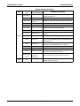
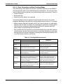
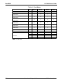
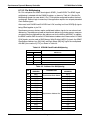
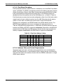
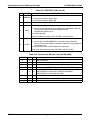
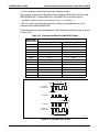
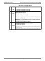
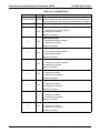
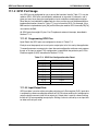
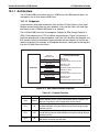
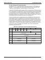
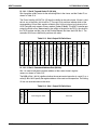
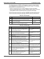
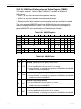
The LH7A404 can boot from either SynchFlash, internal ROM, external Asynchronous
ROM, or external Flash memory. The boot mode is specified at power-on reset by the
Media Change signal (MEDCHG, pin E4) and the Boot Width signals (WIDTH[1:0], pins
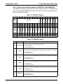
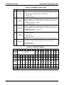
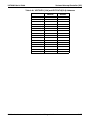
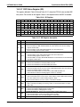
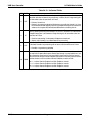
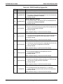
W13 and Y13, respectively) and the Internal Boot pin (INTBOOT, pin Y20). The signal values for each boot mode are shown in Table 3-1.
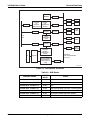
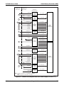
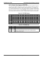
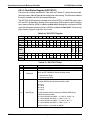
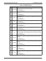
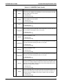
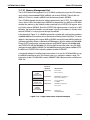
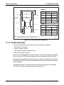
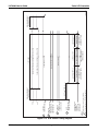
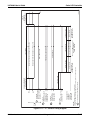
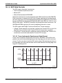
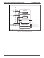
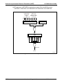
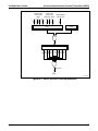
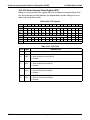
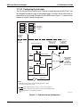
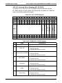
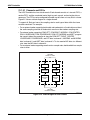
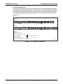
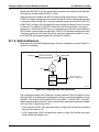
The boot mode determines the memory mapping, as shown in Figure 3-3. To boot from
external Synchronous memory, configure the WIDTH and MEDCHG signals to map SDMC
Bank 3 (nSCS3) to memory location 0x0000.0000. To boot from external Asynchronous
memory, map SMC Bank 0 (nCS0) to memory location 0x0000.0000. Booting from the
internal ROM is described in the next section.
After the LH7A404 has booted, software can reconfigure the mapping.
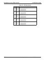
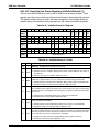
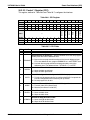
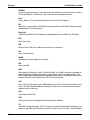
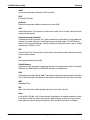
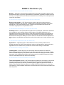
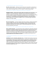
Table 3-1. Boot Mode Signals
BOOT MODE
WIDTH [1:0]
MEDCHG
INTBOOT
8-bit ROM
00
0
0
16-bit ROM
01
0
0
32-bit ROM
10
0
0
Invalid: Do not allow this condition.
11
0
0
16-bit SynchFlash (Initializes device MODE Register)
00
1
0
16-bit SROM (Initializes device MODE Register)
01
1
0
32-bit SynchFlash (Initializes device MODE Register)
10
1
0
32-bit SROM (Initializes device MODE Register)
11
1
0
Boot from internal Boot ROM; see Chapter 4
xx
x
1
3.1.5.1 Internal Boot ROM
Booting from on-chip ROM can also be selected by tying the INTBOOT pin HIGH. See
Chapter 4 for details about using the internal Boot ROM.
3-6
Ver. 1.3 — 27 August 2007
NXP Semiconductors