1
5. INSTALLATION
Two installation examples are detailed on the following pages; mortise and surface, however any combination of
the two can be achieved. Whichever installation method is chosen it is vital to ensure that the lock face plate
and the strike plate align correctly and the gap between the lock face plate and strike plate does not
exceed 8mm when the door is closed.
5.1 Mortise Installation
A typical mortise installation is described with the lock fitted into the door frame and the strike plate secured into the
door. It is possible to install the lock into the door and the strike plate into the frame however with this method
running wiring to the lock requires additional work.
5.1.1 Cutting the mortises
Referring to the dimension drawings in Section 3;
mortises are cut into the door and door frame
suitable to fit the strike plate and lock. Wooden
doors and frames require full mortises where metal
doors and frames, being hollow, often only require
a single rectangle cut-out to accommodate the lock
face plate or strike plate. For these installations the
supplied fitting tabs can be used to secure the lock
and strike plate in place.
The mortise behind the lock body needs to have
enough space to accommodate the wiring.
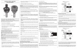
Cut-out in a
metal door to
accommodate
the strike plate.
Cut-out in a
wooden door
frame to
accommodate
the lock.
5.1.2 Wiring the lock
Wires are run from the power supply to the lock. A
hole needs to be drilled in the back of the mortise
to bring the wires out and a connection can be
made to the supplied wire loom which in turn plugs
into the lock. The jumper needs to be positioned
for fail safe / fail secure configuration as per the
instructions on the lock cover.
The Red, Black and Blue wires are essential
connections whilst the Violet and White are
optional. Detailed wiring instructions are found in
Section 6.
5.1.3 Fitting the lock and strike plate
The lock is slid back into the mortise, making sure
that the wiring integrity is maintained and secure in
place with the supplied 10G self-tapping screws.
Before the strike plate is installed the fitting tabs
are secured in behind the cut-out using the
supplied M5 machine screws. The strike plate is
then placed into the cut out and the remaining M5
screws are used to secure it.
© BQT Solutions (SEA) Pte Limited
Strike plate
installed in
the door using
the fitting tabs.
Lock secured
directly into
the door frame.
Page 5