1
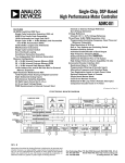
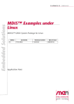
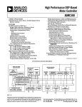
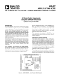
ADMC331
determined by the capacitor and the current source values. An
internal current source is made available for connection to the
external timing capacitor on the ICONST pin. An external
current source could also be used, if required. The four input
comparators of the ADC block continuously compare the values
of the four analog inputs with the capacitor voltage. Each comparator output will go high when the capacitor voltage exceeds
the respective analog input voltage.
VC
V1
VVIL
ADC Timer Block
The ADC timer block consists of a 12-bit counter clocked at a
rate determined by the ADCCNT bit in the MODECTRL
register. If ADCCNT is 0, the counter is clocked at twice the
CLKOUT period, or if ADCCNT is 1, the counter is clocked
at the CLKOUT period. Thus at the maximum CLKOUT
frequency of 26 MHz, this gives a timer resolution of 76.9 ns
when ADCCNT is 0, and 38.5 ns when ADCCNT is 1. The
counter is reset during the high PWMSYNC pulse so that the
counter commences at the beginning of the reference voltage
ramp. When the output of a given comparator goes high, the
counter value is latched into the appropriate 12-bit ADC register. There are four pair of ADC registers (ADC1, ADC2,
ADC3 and ADCAUX) corresponding to each of the four comparators. Each comparator’s register pair is organized as master/
slave or master/shadow. At the end of the reference voltage ramp,
which is prior to the next PWMSYNC, all four master registers
have been loaded with the new conversion count. At the rising edge
of the PWMSYNC, the registered conversion count for each channel is loaded into the DSP readable shadow registers, ADC1,
ADC2, ADC3, and ADCAUX. The controller will then read
these shadow registers containing the previous PWM period
conversion count, while internally the master registers will be
loaded with the current PWM period conversion count.
The first set of values loaded into the output registers after the
first PWMSYNC interrupt will be invalid since the latched value
is indeterminate. Also, if the input analog voltage exceeds the
peak capacitor ramp voltage, the comparator output will be
permanently low and a 0xFFF0 code will be produced. This
indicates an input overvoltage condition.
VREF
ICONST
CAPIN
PWMSYNC
C
ADC
REGISTERS
SGND
ADC
TIMER
BLOCK
ADCAUX
VAUX0
VAUX2
VAUX3
ADC2
ADC3
V3
VAUX1
4-1
MUX
ADMUX0
ADMUX1
Figure 11. ADC Overview
REV. B
MODECTRL (7)
ADC1
V1
V2
VCMAX
t
t VIL
TCRST
TPWM – TCRST
PWMSYNC
COMPARATOR
OUTPUT
Figure 12. Analog Input Block Operation
ADC Resolution
Because the operation of the ADC is intrinsically linked to the
PWM block, the effective resolution of the ADC is a function of
the PWM switching frequency. The effective ADC resolution is
determined by the rate at which the counter timer is clocked,
which is selectable by the ADCCNT Bit 7 in MODECTRL
register. For a CLKOUT period of tCK and a PWM period of
TPWM, the maximum count of the ADC is given by:
Max Count = min (4095, (TPWM – TCRST)/2 tCK
Max Count = min (4095, (TPWM – TCRST)/tCK
MODECTRL Bit 7 = 0
MODECTRL Bit 7 = 1
For an assumed CLKOUT frequency of 26 MHz and PWMSYNC pulsewidth of 1.54 µs, the effective resolution of the
ADC block is tabulated for various PWM switching frequencies
in Table VII.
Table VII. ADC Resolution Examples
PWM
Freq.
(kHz)
Max
Count
Effective
Max
Resolution Count
Effective
Resolution
2.5
4
8
18
24
4095
3230
1605
702
521
12
>11
>10
>9
>9
12
12
>11
>10
>10
MODECTRL[7] = 0
MODECTRL[7] = 1
4095
4095
3210
1404
1043
External Timing Capacitor
In order to maximize the useful input voltage range and effective
resolution of the ADC, it is necessary to carefully select the
value of the external timing capacitor. For a given capacitance
value, CNOM, the peak ramp voltage is given by:
V C max =
CLKOUT
I CONST (T PWM – T CRST )
CNOM
where ICONST is the nominal current source value of 13.5 µA and
TCRST is the PWMSYNC pulsewidth. In selecting the capacitor
value, however, it is necessary to take into account the tolerance
of the capacitor and the variation of the current source value.
–19–