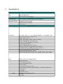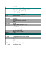
1
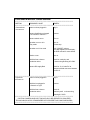
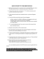
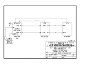
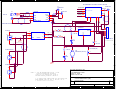
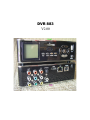
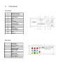
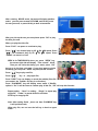
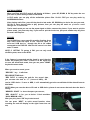
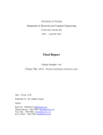
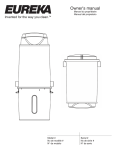
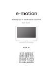
OUTLAND TECHNOLOGY INC. 38190 COMMERCIAL CT. SLIDELL, LOUISIANA USA 70458 (985)847-1104, Fax (985)847-1106 (Email) [email protected] (Website)http://www.outlandtech.com UNDERWATER VIDEO SYSTEM MODEL UWS-3210/3220 UWS-3210/3220 OPERATING INSTRUCTIONS 1. To operate Camera System, all interconnections from the Control Unit, VCR & Monitor, should already be connected but in the event there is a problem drawing # 0010550 shows how those items connect. CAUTION: Insure voltage does not exceed 250 volts AC to the Console. Also power source must be properly grounded. Typically 120 VAC for UWS-3210, 240 VAC for the UWS-3220. 2. Plug Camera Umbilical into Camera and light (Be sure to use a good quality silicon grease for lubrication). Plug topside end of umbilical into Control Unit connector on front panel. 3. After verifying supply power is correct, insure camera, light, recorder and monitor switches are in off position. Plug into power source. 4. Turn Monitor, Recorder and Camera switches on. Select TV on the recorder menu and within a few secs. a picture will appear. 5. Adjust Focus control to get a clear picture. (UWC-560 only) UWC-500 requires the Video Typewriter option. Hit the "Home" key to Zoom out and the "End" key to zoom in. Focus is automatic. To manually focus the UWC-500 hit the "+" key and then "Page up" and "Page down" to focus. To put back into automatic hit the "+" key. 6. Insure "Light Intensity" is at "Min" position. Turn light switch on. Turn control up to test light. Turn back to Min. and Turn switch off. CAUTION: " Light can be operated out of water but will shut down automatically if the temperature exceeds 50c. 7. The CON-3200 console only outputs 24 VDC maximum. 8.) To Use the recorder please refer to the DVR manual: When initially turned on the DVR recorder takes about 20 seconds for the menu to appear on screen. Just select TV and hit enter and a picture should appear from the camera. Note: Although the DR recorder is Equipped to record and playback in multiple speeds the High mode should be used for highest Quality recordings. Read the recorder manual for more details concerning the operation of these recorders. Any problems Please Contact: Outland Technology Inc. 38190 Commercial Ct. Slidell, La. U.S.A. 70458 (985)847-1104, Fax (985)847-1106 EMAIL: [email protected] Website: http://www.outlandtech.com TROUBLESHOOTING GUIDE ******************************************************************************************************* SYMPTOM PROBABLE CAUSE REMEDY ******************************************************************************************************* 1. Camera does Power cord not plugged in Plug in. not come on. Camera Umbilical not plugged in at Console or Camera. Connect. Camera switch not on. Turn on Recorder not on or is in Play mode. Turn onPress stop. Recorder not in line mode Push "VMODE" selector until video appears on the display. See DVR manual for more details. Monitor not on. Turn on. Umbilical has a short or has broken wires. Check for continuity and or shorts using Drawing # C-2303. Camera DC supply Bad Check for 12-16 volts DC at camera umbilical connector between pins B & C. ******************************************************************************************************* 2. Light does Power cord not plugged in Plug in. not come on Umbilical not plugged in at Console or Light Connect. Umbilical has a short or has broken wires. Check for continuity and/ or shorts using Drawing # C-2303 ******************************************************************************************************* CAUTION: CAMERA AND LIGHT SHOULD ONLY BE OPENED, BY QUALIFIED TECHNICIANS,IN A DRY ATMOSPHERE WITH PROPER TOOLS AND WORK AREA. ******************************************************************************************************* QUICK START TO THE NEW DVR 883 1) With camera and monitor connected, and on, push the DVR power button. This takes about 30 secs, to show the main menu. Please wait. 2) To show the camera live, scroll down to “TV”, with the arrow keys and push the center arrow key to select. 3) If the camera and monitor are connected and on, a picture will appear quickly. 4) To record, hit the record button and 4 lines will appear: a. Path, could be C or USB (if a USB device is plugged into the front) b. Memory size of drive plus how much is available. c. Video Quality, High is normally selected. Med and low are available. d. OK and Cancel. 5) “C” is usually highlighted and if you want to record to the internal Hard drive Just leave it alone. 6) Skip past video quality to OK and select enter. 7) The unit will start recording and a tiny red dot will appear on the bottom left side of the screen indicating it is in record. 8) To stop, hit the stop button. It may take a few seconds to actually say stop on the screen. It is closing the file and if it is large enough may take 5-10 secs. 9) To playback the video hit the menu button and scroll up to “Recorded files” Hit the select button to select “Recorded files”. 10) Select which file to play by using the arrow keys and enter. Hit the select button to select “Recorded files”. Select which file to play by using the arrow keys and enter. For more detailed operation of this DVR see the manual supplied with the system. Once you get the video files to your computer see the folder VLC in the DVR hard drive. Download it into your computer and use it to play and pull stills from the video. This program is free to distribute and use. Optional, only when ordered: 5100A/I, INTERNAL Video Time/Date/Text Typewriter, "For typing on screen" A. The Video typewriter powers up whenever the console is plugged in. The video always goes through the Video typewriter B. After powering on the system the screen should go to page zero "0". Anything in page zero will be displayed as well as time and date, if it were on the screen when it was powered off. C. Hit the “H” Key and the main menu will appear on the screen. D. Menu: (KEY)(FUNCTION) E EDIT PAGE 0 C CLEAR PAGE 0 T TIME OFF D DATE OFF S SET TIME R RESET SYSTEMS P SCALE (Ruler) X Cross Hair (Pointer) M Camera Mode I SET INTENSITY 1) E; Go to the Page you want to edit by touching the number key. Touch the letter “E”. This will bring you into the edit mode and you should see a Blinking cursor at the top left corner of the screen. Type in anywhere on the screen and when you finish hit the “ESC” key. The text will store in memory and the cursor will disappear. 2) C; Go to the page you want to clear and hit the letter C. The following will appear: ARE YOU SURE YOU WANT TO CLEAR PAGE 0 ? (Y/N) This will clear the page of all characters except the time and date. Select yes or no. 3) T; Hitting this key will turn the time either on or off. 4) D; Hitting this key will turn the date either on or off. 5) S; Hitting this key will allow you to set the time and date. The following will appear: ( 12,51,5,21,99) ENTER HR,MIN,MONTH,DAY,YEAR Input the time and date as shown with comas between each item followed by "ENTER". 6) R; Hitting this key will clear all pages. The following will appear: ARE YOU SURE YOU WANT TO CLEAR ALL MEMORY ? (Y/N) Select yes or no. The time and date screen. will remain on 7) P; Hitting this key will cause the Video Ruler to appear on the bottom of the screen. The Video typewriter time date features will continue to operate. The active keys to use this feature are: “O”, sets scale factor. 1=1, 2=2, 3=3, etc. for every tic mark. Minus for tic marks to the left and + for each tic mark to the right. The digital display below and to the left of the scale is where on the Ruler the cursor marker is in relation to the center of the scale. “Left Arrow” Key moves the cursor to the left on the ruler. “Right Arrow” Key moves the cursor to the right on the ruler. The digital display moves up and down as these arrow keys are used. “Home” Key moves the ruler tic marks wider. “End” Key moves the ruler tic marks closer. “Page Down” moves the center(offset) of the ruler Left. “Page Up” moves the center (offset) of the ruler Right. To use this feature set the scale factor for the required measurement. Move the center (offset) of ruler to the center of the item to be measured. A reference must be used to accurately measure with Video Ruler. If Laser dots are use then scale the to those dots. Once the ruler is scaled using the and “Home” Keys, use the arrow key to show the measurement. the the ruler “end” 8) X; Hit this key and a Crosshair will appear on Screen. Use the cursor keys to move the crosshair (Video Pointer) around the screen. In this mode the Scale will disappear. The time and date will remain on Screen and all page functions will work also. 9) I; Hitting this key will bring up the following: SET INTENSITY LEVEL 0 MIN, 15 MAX > Default is 3. If you enter 0 then the characters will turn black. If 14 or 15 are entered then the character will probably be a little too bright. Play around with this and set for best display. 10) M; Hit this key and the camera control menu will appear. See Multi Camera control for details about this function. Note: When in the Crosshair or Scale mode you can go to Camera mode by hitting any key not used to operate those functions. Example: Space Bar. Multi Camera control, Hit the “M” key and select which camera to control. If several cameras are connected to the serial data line each camera must be set to a different address. The single camera operation is always camera 0 "zero". Call Outland for more details. To control a camera the following keys are used: Up/Down Arrow Controls camera tilt up/down Left/Right Arrow Control camera Pan left/right “Home” = Zoom Telephoto “End” = Zoom Wide “Page up” = Focus Far “Page down” = Focus Near “+” key = Auto-Focus on/off IF AT ANY TIME THE VIDEO TYPEWRITER LOCKS UP, THE SYSTEM CAN BE RESET BY UNPLUGGING THE CONSOLE FROM THE POWER SOURCE. SIMPLY TURNING THE CAMERA, MONITOR AND VCR OFF WILL NOT WORK. A B C D E 0010460 MODEL 5100 VIDEO OVERLAY OPTION J1 AUDIO OUT J3 4 1 MIC IN 3 MIC L IN GND VIN GND VID IN 5(PWR) GRN 8 9 AUDIO MIXER AUDIO LINE IN ISOLATED 12 COMM+ L OUT GND 4 2(DATA) BRN 6 7 13 COMM- GND J6 U7 LM7815CT 1 AC PLUG 3 J7 2 S1 CAMERA POWER 4 Red wire 5 Black wire 1 IN OUT R1 2.7K 1W 2 S2 LAMP POWER C1 10uF 50V Black wire 1 AC RECPTACLE MS-3102A-18-08S White wire R2 2.7K 1W 3 CAMERA CABLE D1 LED N A B C D E F G H 3 2 1 L MEANWELL RS-75-1 +V N -V GND 24VPS 1 2 GND 3 J2 IBM KEYBOARD V+ J5 4(GND) ORG V- 4 5 VID OUT J4 AUDIO OUT 0010226 VIDEO OUT 1(CLK) BLUE Fan EFB0424LD (24V Fan) R3 CT2158-ND (5K) 2 J8 2 2 D2 LED 3 AC RECPTACLE J9 OUTLAND TECHNOLOGY INC. NOTES: 1. FOR THE INTERNATIONAL OPTION, J8 AND J9 ARE IEC RECEPTICLES QUALTEK PN 710W-00/01, FOR DOMESTIC USE J8 AND J9 ARE NEMA OUTLETS QUALTEK PN 738W-X2/03 1 2. TO DELETE VIDEO OVERLAY MODEL 5100 ADD DOTTED LINE WIRES BETWEEN VIDEO OUT JACK J2 AND PIN A OF J6. 3. ADJUST 24 VPS TO 26.5 VOLTS. A B C 38190 COMMERCIAL COURT SLIDELL, LA. 70458 (985)847-1104, FAX 1106 1 Title CU-3200 POWER SUPPLY (LED) Size A Document Number 0204099 Date: Monday, January 28, 2008 D Rev C Sheet of 1 E 1 OUTLAND TECHNOLOGY INC. UWL-400 UNDERWATER LIGHT Operating and Maintenance Procedures Reference: DRAWING UWL-400 Installation and Operation: A. The UWL-400, can be mounted to your Camera, ROV, Helmet or Hand bracket by using DHM-60 OR HM-300 helmet bracket. B. With Power Off, lubricate the light mating connector with a light coating of silicon lubricant. Slide the locking sleeve of the mating connector back. Align the raised dot on the connector with the large connector pin on the light connector and plug in. Securely tighten the locking sleeve. THERE ARE NO USER SERVICEABLE PARTS INSIDE. PLEASE SEND BACK TO THE FACTORY FOR SERVICE. The only maintenance required is to flush with fresh water and dry for storage. OUTLAND TECHNOLOGY INC. 38190 Commercial Court Slidell, Louisiana U.S.A. 70458 Ph.(985)847-1104, Fax 1106 Email: [email protected] Website: www.outlandtech.com LIMITED WARRANTY Outland has a strong commitment to high quality production. Each product has a twelve (12) month limited warranty against defects in workmanship or materials with the exception of those outlined in the limitations and exclusions. Outland will repair or replace at its discretion the defective components. Limitations and Exclusions • The limited warranty does not cover damage caused by improper use, poor maintenance or accidental damage of the product or its components. • The limited warranty does not cover items subject to wear including but not limited to view ports, o-rings, umbilical, unless found to be defective in workmanship and/or materials. • The limited warranty does not cover any modification made to these products without authorization from Outland Technology Inc. • The limited warranty does not cover lamps. • The limited warranty does not cover components damaged due to incorrect power connection per user’s manual. • The limited warranty does not cover items not actually built by Outland. Example (DVD recorder, Monitor etc.). That would be covered by the manufacturer's warranty. Advertising claims made by us represent our honest opinion of the qualities and features offered by the products described. We disclaim any warranties expressed or implied, including warranties of merchantability and fitness for a particular purpose, except as provided herein. In no event shall Outland Technology be liable for consequential damages of any kind. Shipping All returns for warranty service must be authorized by Outland. You must call or email Outland for a RMA#. The assigned RMA (Returned Materials Authorization) number which must be clearly indicated on each item returned for service. NOTE: To submit a product or its components for warranty a RMA form must be completed. Please complete as best and detailed as possible. For warranty shipping within the first 30 days, Outland will pay for ground shipment on domestic orders incoming and outgoing to a maximum of $75.00 each way. International shipments will be credited up to $75.00 US for incoming and outgoing freight charges to Outland Technology Inc. After 30 days the client is solely responsible for shipping to and from Outland Technology Inc. During the first 30 days of the warranty period, should faster delivery service be requested, a $75.00 US credit towards expedited freight for each applicable leg will be given. If you have any questions regarding the installation and operation of this equipment, or if more information is needed contact: OUTLAND TECHNOLOGY,INC., 38190 Commercial Ct.,Slidell, LOUISIANA USA 70458 (985)847-1104 FAX (985)847-1106 (Email) [email protected] (Website) http://www.outlandtech.com ENGLISH Federal Communications Commission (FCC) Statement This Equipment has been tested and found to comply with the limits for a class B digital device, pursuant to Part 15 of the FCC rules. These limits are designed to provide reasonable protection against harmful interference in a residential installation. This equipment generates, uses and can radiate radio frequency energy and, if not installed and used in accordance with the instructions, may cause harmful interference to radio communications. However, there is no guarantee that interference will not occur in a particular installation. If this equipment does cause harmful interference to radio or television reception, which can be determined by turning the equipment off and on, the user is encouraged to try to correct the interference by one or more of the following measures: - Reorient or relocate the receiving antenna. - Increase the separation between the equipment and receiver. - Connect the equipment into an outlet on a circuit different from that to which the receiver is connected. - Consult the dealer or an experienced radio/TV technician for help. Warning: A shielded-type power cord is required in order meet FCC emission limits and also to prevent interference to the nearby radio and television reception. It is essential that only the supplied power cord be used. Use only shielded cables to connect I/O devices to this equipment. You are cautioned that changes or modifications not expressly approved by the party responsible for compliance could void your authority to operate the equipment. IMPORTANT SAFEGUARDS Warning: 1. Read all of these instructions. 2. Save these instructions for later use. 3. Unplug this monitor from the wall outlet before cleaning. Do not use liquid cleaners or aerosol cleaners. Use a damp cloth for cleaning. 4. Do not use attachments not recommended by the monitor manufacturer as they may cause hazards. 5. Do not use this monitor near water. For example near a bathtub, washbowl, kitchen sink, or laundry tub, in a wet basement, or near a swimming pool, etc.. 6. Do not place this monitor on an unstable cart, stand, or table. The monitor may fall, causing serious injury to a child or adult, and serious damage to the appliance. Use only with a cart or stand recommended by the manufacturer or sold with monitor. Wall or shelf mounting should follow the manufacturer's instructions, and should use a mounting kit approved by the manufacturer. 7. Slots and openings in the cabinet and the back or bottom are provided for ventilation, and to insure reliable operation of the television receiver and to protect it from overheating, these openings must not be blocked or covered. The openings should never be blocked by placing the monitor on a bed, sofa, rug, or other similar surface. This monitor should never be placed near or over a radiator or heat register. This monitor should not be placed in built-in installation such as a bookcase unless proper ventilation is provided. 8. This monitor should be operated only from the type of power source indicated on the marking label. If you are not sure of the type of power supplied in your home, consult your monitor dealer or local power company 9. This monitor is equipped with a three-wire grounding type plug, a plug having a third (grounding) pin. This plug will only fit into a grounding-type power outlet. This is a safety feature. If you are unable to insert the plug into the outlet, contact your electrician to replace your obsolete outlet. Do not defeat the safety purpose of the grounding- type plug. 10. Do not allow anything to rest on the power cord. Do not locate this monitor where the cord will be abused by persons working on it. 11. Follow all warnings and instructions marked on the monitor. 1 ENGLISH 12. For added protection for this monitor, when it is left unattended and unused for long periods of time, unplug it from the wall outlet. This will prevent damage to the monitor due to power-line surges. 13. Do not overload wall outlets and extension cords as this can result into fire or electric shock. 14. Never push objects of any kind into this monitor through cabinet slots as they may touch dangerous voltage points or short out parts that could result in a fire or electric shock. Never spill liquid of any kind on the monitor. 15. Do not attempt to service this monitor yourself since opening or removing covers may expose you to dangerous voltage or other hazards. Refer all servicing to qualified service personnel. 16. Unplug this monitor from the wall outlet and refer servicing to qualified service personnel under the following conditions: a. When the power cord or plug is damaged or frayed. b. If liquid has been spilled into the monitor. c. If the monitor has been exposed to rain or water. d. If the monitor does not operate normally by following the operating instructions. Adjust only those controls that are covered by the operating instructions as improper adjustment of other controls may result in damage and will often require extensive work by a qualified technician to restore the monitor to normal operation. e. If the monitor has been dropped or the cabinet has been damaged. f. When the monitor exhibits a distinct change in performance- this indicated a need for service. 17. When replacement parts are required, be sure the service technician has used replacement parts specified by the manufacturer that has the same characteristics as the original parts. Unauthorized substitutions may result in fire, electric shock, or other hazards. 18. Upon completion of any service or repairs to this monitor, ask the service technician to perform routine safety checks to determine that the monitor is in safe operating condition. 12’’TFT COLOR MONITOR 1. Installing the Monitor Unpacking Open the shipping cartons and check the contents. If any items are missing or damaged, contact your dealer immediately. The package should include the following items: ․TFT color monitor ․User's guide ․Power cord ․Signal cable ․DC power adapter ․Audio cable Installing the Base Follow these steps to install the base: 1. Turn the monitor down. 2. Assembly the base to the arm with screw. 3. Tie the screw with a coin. Installing the Monitor This monitor is equipped with an auto sensing DC power adapter for voltage ranges 100-240VAC, 60/50Hz. Confirm the line voltage designation on the rear panel of the monitor. Follow these steps to install the monitor: 1. Before you connect the cables, made sure that the monitor and the system unit power switches are 2 ENGLISH off. 2. Plug one end of the 15pin-signal cable to the monitor and the other end to the video signal connector at the rear of the system. Tighten the two screws on the cable connector. 3. Connect the DC power cord to the DC jack. 4. Connect the power cable. 2. Control Functions The monitor digital control functions are located on the front panel. They are shown in the figure below and described in the following paragraphs. 1.Power Switch with Indicator LED 2.Function Keys 3. Function Select With the △ and ▽ knobs, you can adjust the speakers volume. Press the MENU/SELECT knob to show the OSD menu. Than use the △ and ▽ knobs to select a function. Press the AUTO/EXIT knob to close the OSD menu. You can hold the AUTO/EXIT knob for more than 3 second to adjust the image quality automatically. The OSD menu will close automatically after 3-10 seconds without operation and saves any changes you have made. 4. Function Adjustment 1.Signal Select VGA DVI Exit - Select the image signal coming from the VGA cable. - Select the image signal coming from the DVI cable.(option) - Close the Signal Select OSD menu. 2.Video Brightness Contrast Black Level Exit - Adjust the luminance level in the image. - Adjust the difference in luminance between light and dark areas of the image. - Adjust the black Level in the image. - Close the Video OSD menu. 3.Audio Volume - Adjust the volume of speakers. Exit - Exit the Audio OSD menu. 4.Color Color Temperature User - Adjust the R.G.B. gain level. 6500K - Select color temperature to 6500°K. 9300K - Select color temperature to 9300°K. Exit - Close the Color Temperature OSD menu. Flesh Tone - Adjust the flesh tone of the image. Hue - Adjust the shade of the image color. Saturation - Adjust the saturation of the image color. 3 ENGLISH Exit - Close the Color OSD menu. 5.Image Auto Tune H. Width H. Phase H. Position V. Position Exit 6.Language - Adjust geometry of the image automatically. - Adjust the horizontal sync size of signal. - Adjust the horizontal sync phase of signal. - Adjust the horizontal position of the image. - Adjust the vertical position of the image. - Close the Image OSD menu. - Sets the language of the OSD windows. 7.Tools OSD Control Recall Sharpness Exit 8.Exit OSD Timer - Setting the OSD menu display time. OSD H. Position- Adjust the horizontal position of the OSD menu. OSD V. Position- Adjust the vertical position of the OSD menu. Exit - Close the OSD Control OSD menu. - Recall the factory default setting. - Adjust the picture display more clear. - Close the Tools OSD menu. - Close the OSD menu. 5. Micro-controller Features The micro-controller automatically detects the video board installed in your system. When you turn on the monitor, the micro-controller first checks the display mode memory stored in the user setting area of the video board, and then the factory presetting area. It then adjusts to the proper display mode. 6. Display Modes Memory The micro-controller has the memory capacity to store different display modes, including timing formats and display-settings. Factory Presetting Area There are some preferred display modes preset in the micro-controller. These display modes are preset at the factory and include the most popular display modes currently available. The micro-controller searches for a proper display mode in this area if it fails to find a proper display mode in the user setting area. MODE 1. 2. 3. 4. 5. 6. VGA VGA VGA VESA/75 VESA/60 VESA/75 Resolution (Dots*lines) 640×350 720×400 640×480 640×480 800×600 800×600 Horizontal Freq.(KHz) 31.5 31.5 31.5 37.5 37.9 46.9 4 Vertical Freq.(Hz) 70 70 60 75 60 75 Remark Non-interlaced Non-interlaced Non-interlaced Non-interlaced Non-interlaced Non-interlaced ENGLISH 7. Signal Connector Pin-outs To connect VGA, 8514A or IBM-compatible graphics adapters, use a 15 pin mini D-type male connector. 15-pin Mini D-type Male Connector Pin Assignment 1 Red Video 2 Green Video 3 Blue Video 4 Ground 5 No Connection 6 7 8 9 10 Red Ground Green Ground Blue Ground No Connection Sync Ground 11 12 13 14 15 Ground Serial Data/I/O H. Sync V. Sync Serial Clock Input 8. Power Saving Feature When the power saving active them the power indicator LED will be from Green Light to Amber, And power saving feature complies with these VESA power saving modes: Power Consumption Normal On On Green <30W Stand-by Off On Amber < 3W Suspend On Off Amber < 3W Off Off Off Amber < 3W The monitor uses the H. Sync and V. Sync signals to determine the operation mode to enter. The monitor power-saving feature automatically turns off H. Sync and V. Sync if there is no input from the system for a certain period of time. To use this feature, you need a green PC that is compliant with the VESA power saving feature or a software utility to detect system input such as keyboard or mouse. Mode H. Sync. V. Sync. LED Time Settings Time settings are adjusted from the system unit by software. To fulfill the requirements in the NUTEK specification 803299/94 the total time from indicated inactivity to Power Saving position A2 (VESA OFF) must not be set more than 70 minutes. We recommend you switch off the monitor when you do not intend to use it for awhile. 5 ENGLISH 9. Specifications Model LCD Panel Size: Pixel Pitch: Brightness: Contrast Ratio: Response Time: Maximum viewable size Video Input Display area Power supply (Universal) Input voltage: Consumption External controls Horizontal frequency Vertical frequency Dimensions(with carton) Max. Resolution Power Saving Plug & Play Weight 288 12” 0.3075mm 400cd/㎡ 500:1 35ms(typ.) 12 inch(30.5cm) Analog:15-pin, D-sub connector Digital:DVI connector(option) 246mmx184mm 12V DC/2.5A 30watts maximum Power-switch,VGA,DVI(option),Brightness,Contrast, Black level,Volume,Color tempeture(User,6500°K, 9300°K),Flech tone,Hue,Saturation,H-width,H-phase, H-position,V-position,OSD control,Recall,Sharpness,Exit 30-47KHz 50-75Hz 365mm×195mm×340mm (W×D×H) 800×600 (Non-Interlaced) With EPA standard DDC 1/2B N.W.:2.4Kgs G.W.:3.0Kgs Ambient temperature Operation: Non-operating Humidity Operating: Storage: *Specifications are subject to change without notice. 6 5°C – 35°C -20°C – 60°C 20%-80% 10%-90% DVR 883 V2.00 Congratulations for having bought this product. We are sure that you will be entirely satisfied with this multi-media player/recorder. Please take some time to read thoroughly this manual so that you can use the unit to its best possibilities. Keep this instruction manual handy and refer to it when you need it. In case of faulty operation, do not attempt to repair the unit yourself. Opening the unit have you exposed to electrocution hazards. Please refer to a qualified person. Do not use this unit near any heating source, especially hot air vents, stove or any other appliance producing heat. Do not expose this unit to temperatures lower than 5 ℃ or higher than 35 ℃. Do not place your unit in front of a light projector or near a heating source. Do not use any substance containing alcohol, gasoline, detergent or any other flammable products to clean the surface of the unit. Do not drop the unit or let it be subjected to impacts that could seriously damage your unit or the hard drive. During the installation of the hard drive, please assure yourself to unload the unit of any electrostatic charge. Do not let any liquid or foreign substance be inserted inside the unit that could result in a short circuit with fire or electrocution hazards. Do not cut, deteriorate, or place any heavy object on the power cable that could result in a short circuit with fire or electrocution hazards. Disposal of Used Electrical & Electronic Equipment The meaning of the symbol on the product, its accessory or packaging indicates that this product shall not be treated as household waste. Please, dispose of this equipment at your applicable collection point for the recycling of electrical & equipments waste. In the European Union and Other European countries which there are separate collection systems for used electrical and electronic product. By ensuring the correct disposal of this product, you will help prevent harm to the environment and to human health, which could otherwise be caused by unsuitable waste handling of this product. The recycling of materials will help conserve natural Resources. Please do not therefore dispose of your old electrical and electronic equipment with your household waste. For more detailed information about recycling of this product, please contact your local city office, your household waste disposal service or the shop where you purchased this product. 1 Important Information In case of a breakdown: Have the player checked by a qualified technician if: • The power supply or the plug is damaged • An external object or a liquid went inside the player • The player was under the rain or in a humid area • The player dose not work properly • The performances of the player have drastically deteriorated • The player has been dropped down or the cover has been damaged DO NOT OPEN THE COVER AND DO NOT TRY TO REPAIR THE PLAYER YOURSELF. 2 Important safety instructions Make sure that your product is turned off while you connect cables between DVR 883 and your monitor. DVR 883 is designed to switch automatically to sleep during USB (rear) cable connection or disconnection. This is not a fault. Make sure that the hard disk jumper which will be installed on the DVR 883 is on “Master” position. If not, the hard disk will not be recognized. During the install of hard disk, make sure that it is formatted and partitioned before hand. WINDOWS 98 and ME don’t support NTFS files system as well as any other hard disk formatted in NTFS. To use the DVR 883 with one of those systems you need to format the hard disk in FAT 32. Never turn off the unit during an upgrade with a new firmware. If this happens, appliance could stop working properly and you would lose the warranty validity. the 3 Features All Internet Video Format This device supports video formats including RM/RMVB, H.264, MPEG-2/4, DivX3/4/5, XviD, FLV, and WMV. Preview, fast forward, fast backward( with sound), pause, DivX subtitle feature are supported. All Internet Music Format This device supports popular music formats including MP3, WMA, OGG Vorbis, AAC, RA, and FLAC. Subtitle can be displayed when listening to MP3 music (external subtitle file music exist). High Definition Photo Playback This device supports popular Photo formats including JPEG, GIF, BMP, and PNG. Popular Digital photo Frame feature is supported, including slide show, background music, and zoom. The most distinguished feature is supports video clips from Youtube (FLV video), RMVB from popular many video websites, and decode up to 16 million pixels high definition photo in 2 seconds. Personal Video Record Function This DVR 883 has a feature to record live Video or DVD program at DVD quality (D1 resolution, 720x576/720/480), with standard MPEG-4 encoder and AVI file container. This recorded AVI can be playback Windows Media Player without any additional plug-in, on many platform including PMP, PC, Smart Phone, etc. Connectivity and Storage SATA HDD - This device has build in SATA interface. It can support most popular 3.5” and 2.5” SATA disk from market. File system: Support NTFS (read and write. No partition and file size limitation) USB 2.0 Client. After installing an internal SATA HDD, and connecting to PC through USB interface, this device connection works as USB device. User can exchange the movies, music and photo with PC through USB 2.0. USB 2.0 Host - This device supports external USB device including USB HDD, Flash-Disk, Card reader, and Digital Camera. User can directly connect those device to the DVR 883 and playback multimedia content. Network Media Stream – By Ethernet 10/100/1000Mbps, user can watch video and listen to music stored in home network. Home NAS – When the DVR 883 and PC connect to home network (Ethernet), Using PC file manager user can manage and exchange file between them through network. TV – After DVR 883 was connected to a monitor, user can enjoy the multimedia entertainment content with family with superior consumer electronics user experience. 4 Specifications Network LAN Internal Storage Network neighborhood Network Attached Storage (NAS) Storage 2.5”/3.5” SATA-I or SATA-II HDD (1.5Gb/s or 3.0Gb/s) USB Mass Storage USB Mobile HDD, Flash-Disk USB Card Reader (SD/MMC) Digital Camera Playback Formats Video/Movie Real Media 8/9/10, D1 @ 30fps(.RM,.RMVB), 5.1ch RMVB movie Flash Video scale to D1 @ 30fps (.FLV) MPEG-1 (.MPG, .DAT) MPEG-2 720p (.MPG, .MPEG, .VOB, .TS, .M2TS) MPEG-4 720p @ 30fps (.AVI, .MP4, .TS) DivX 3.11/4/5, 720p @ 30fps (.AVI, .DIVX) XviD 720p @ 30fps (.AVI) WMV7/8 720p @ 30fps (.ASF, .WMV) WMV9/VC-1 SP/MP, 720p @ 30fps (.ASF, .WMV) H.264 BP/MP/HP, D1 @ 30fps (.AVI, .MKV, .MOV,.TS) AVI audio codec: MP3, AC3, ADPCM, WMA Multiple embedded audio track switch Subtitle: SUB (MicroDVD format), SRT (SubRIP format), SMI, multiple Music MPEG-1 Layer 3, 24~320kbps (.MP3) Ogg Vorbis (.OGG) AC3 (embedded in movie) Microsoft PCM Wave (.WAV) Real Audio (.RA) Advance Audio Coding LC (.AAC) Microsoft Windows Media Audio WMA7/8, 16~384kbps (.WMA). No FLAC (.FLAC) MP2 (.MPA) Subtitle: LRC (.LRC) JPEG up to 20 mega pixels (.JPG) GIF (.GIF) PNG (.PNG) Photo BMP (.BMP) Record Format Video Audio A/V Input MPEG-4 ASP D1 @ 30fps (NTFS/PAL), MP3 Stereo Quality setting at 3 level (HQ/MQ/LQ) AVI file format (.AVI) Composite, RCA L/R Hardware Composite, RCA L/R Video Output CVBS (D1) YPbPr (720p) VGA (640x480, 800x600, 1024x768) HDMI 1.2 Audio Output RCA L/R SPDIF 5.1 channel output (RAW AC-3) 2 x OTG high speed RJ45 (10/100M Ethernet) USB 2.0 Network Power Operation File System Language Display Cooler External Power Adapter (UL, cUL) Input: DC +5V/3A, +12V/2A Output: DC +5V/3A, +12V/2A 0 ~ 40 ℃ Others NTFS (no partition size and file size limitation) FAT16/32 HFS+ EXT2/3 VFAT Chinese/English LCD display with blue backlight 8CM Fan cooler inside 5 Front panel Front Panel: 1 2 3 4 5 6 7 8 9 10 11 12 13 Infrared receiver SD card reader Left/Preview Enter Up USB Host Power On/Off Right/Function Down Home Menu Video Mode Stop Record Rear Panel: 1 2 3 4 5 6 7 8 9 AV Output YPbPr Output AV Input Optical Output HDMI Output LAN Power Jack USB Connect Coax Output 6 Remote control POWER: Power On/Off MUTE: Silence V-MODE: AV / YpbPr / HDMI Switch DISPLAY: Display File Information SUB-T: Caption PHOTO:Enter PHOTO Mode MOVIE:Enter MOVIE Mode MUSIC:Enter MUSIC Mode TV: Enter AV Signal Input Mode Fast Backward Fast Forward FUNCTION: File Copy Function, Such as Rename, Copy, New File Name. Play Last File Play Next File HOME: Back to Home Mode SF: Slow Motion Synchronization UP: UP DOWN : DOWN LEFT : LEFT/Back to Last Mode/Left Turn Picture RIGHT:RIGHT/Right Turn Picture OK: ENTER STOP/EXIT: Stop to play PLAY: PLAY/PAUSE PLAYLIST: Enter PLAYLIST Mode SEEK:Random Play PLAYMODE: Play, Random Play, Repeat Play, Picture Display Mode Select 9PIC:Play First 9 Picture Together In Same Screen ZOOM: Zoom In/Out RECORD: Record AV Signal VOL+/VOL- : VOLUME+ / VOLUME- 7 Hard disk insertion 8 Connections AV connection Please connect the device as shown in the picture below. After wards, turn the DVR 883 on and then also the monitor. Please wait some 3 0 seconds while the file loading process completes. Press “V-mode” key in your remote control or on the front panel to visualize the image in your screen. Important, “V-Mode” key switches the video signal output between AV/YPbPr/HDMI. If after connecting the unit no image appears in the screen, press several times the “V-Mode” button. It is possible that image doesn’t appear because the video signal output has been wrongly selected. YpbPr connection Connect player’s YpbPr port to TV’s YpbPr port respectively. You must use the YpbPr cable for and the red and white connectors of AV cable for sound signal. signal HDMI connection If your monitor has a HDMI Port, you can use HDMI cable to connect to the DVR 883. Coaxial and optical output (5.1ch) If you have a 5.1 channel sound system to enjoy the surround sound during playing you can use the coaxial audio output and optical audio output. 9 Menu When you turn on the DVR 883 it will display the welcome picture like right (it need few second to wait, please be p at i e nt ) then it will display like below picture: The DVR 883 can recognize many partition and can also recognize a SD card and USB device. After that, the DVR 883 is ready to work for you, please enjoy it. MENU will show MOVIE, MUSIC, PHOTO, ALL FILES, RECORDED FILE, TV, SETTING, for you select, user can use remote or front panel control “UP” or “DOWN” key to choice the one you want, press “LEFT” key can back to last mode, except on “SETTING” mode, press “HOME” key can back to “MENU” mode. On “MOVIE” mode, it only can play video file, on “MUSIC” mode it only can play audio file, on “PHOTO” mode, it only can play picture file, on “ALL FILES” mode, you can play all kind file, it support “MUSIC SLIDESHOW”, on “RECORDED FILE” mode, it can record AV file. MOVIE PLAYING When chosing Home menu, MOVIE, MUSIC, PHOTO, ALL FILES, RECORDED FILE,it will show all partition,SD card,USB & PLAY LIST: In here you can use the remote or front control UP, DOWN & OK key,to select the one you want. After Enter MOVIE, MUSIC, PHOTO, ALL FILES, RECORDED FILE ,you can press remote “MOVIE” key enter movie mode, press “MUSIC” enter Music mode, press “PHOTO” key enter photo mode, press “TV” key enter AV signal input mode, If without AV signal input the screen will become black. You can press “home” back to home mode. After entering, MOVIE mode, the menu will display partition select,you can press remote UP, DOWN, and OK key, enter the one you want, or press left key to back to last mode. After you pick up the one you want please press “OK” to play the One you want. When you play the video file: Press “PLAY” can pause or continue to play; Press “” can forward play by X2 X4 X8 speed; Press “” can backward play by X2 X4 X8 speed; Press “ZOOM” can zoom in or out; SEEK is for TIME SEARCH, when you press “SEEK” key, the screen right side will display “Time search” block, Then you can choice the timing you want, press “OK” key to go to the time you want., if you don’t want to choice the timing you can press “SEEK” key and quit this function. Press “|” key to play next file; Press “|” key to play upper file; Press “SUB-T” key can display or cancel the subtitle (if the file not content the subtitle this key is no function); Press “PLAYMODE” key will display menu mode. If Shuffle option is “On” it will be come to random play all the file, “Off” will stop this function. Repeat option:“None” is nothing,“Single” is repeat play single file,“Folder” is repeat all the file on folder. STOP key is stop play file. Note: After setting finish ,press one time PLAYMODE key, it will quit that mode, When play file, can not use the left key to back to upper mode. MUSIC PLAYING Enter MUSIC mode, It will display some f i l e s , press UP, DOWN, and OK key will enter the f il e you want, or press LEFT key back to last mode. Select the one you want play, the press “OK” to play. When playing audio file you can : Press UP, DOWN and OK key to select other file; Press PLAY key to pause or keep playing; Press key, can work 2 time fast play; Press key is no function; Press | key to play next audio file; Press | key can play upper audio file; Press SEEK key can choice the one you want; Press PLAYMODE key can select random or repeat play. PHOTO PLAYING Enter PHOTO mode, you can use UP, DOWN and OK key to pick up the one you want, or press LEFT key back to last mode. In SETTING if setting slideshow time is 0 seconds,that will automatically repeat displaying that picture;if settings slideshow time is 5 seconds,it will automatically play all the picture in your file, and every picture will stay on 5 seconds. When playing the picture, press “LEFT” key, the picture will left turn from 90° 180° 270° 0°. Press “RIGHT” key picture will right turn from 90° 180° 270° 0°; Press “ZOOM” key it will X2 X3 X4 X5 change the size ; If use the “LEFT”, “RIGHT”, “ZOOM” function, the slideshow function will stop, after you press “PLAY” key two times, it will automatic play again. PLAYMODE key can select use, repeat, random play. But on the photo mode , PLAYMODE will have another function , after setting random or repeat, press PLAYMODE key will display next scene as below: “None” is normal display; “Top to bottom” is from the top to bottom display; “Bottom to top” is from the bottom to top display. FILE MANAGEMENT When you Enter ALL FILE mode it will display all folders ,press UP, DOWN ,& OK key enter the one you want or press left key to back to last mode。 In FILE mode, you can play all the audio/video picture files. On ALL FILE you can play music by SLIDESHOW function. After playing audio files, press left key back to last mode, UP, DOWN key to choice the one you want, OK key to enter picture folder to play pictures, then you can play the music a s p i c t u r e s w o r k t h o u g h a s a s l i d e s h o w. Choice music mode you can use the repeat signal or folder, same as the picture, if you want to quit the picture mode, just press stop key, if you want to quit the music too, just press another stop key, then the music will stop too. RECORD The DVR 883 has a very powerful recording function. It can help users record AV input to t h e i n t e r n a l HDD, o r e x t e r n a l U S B d e v i c e , through the AV to AV cables connected to the DVR 883. After the AV source is on then enter TV mode. NOTE: If SETTING TV system is PAL, you can only work the PAL system, same as the NTSC. If the Camera is connected and the signal is good, then the screen will display the video. If there is no AV signal the s c r e e n will show black mode, then you can press “HOME” key back to menu mode. When you want to record, press “RECORD” key ,it will show RECORD SETTING block: “REC PATH” is setting the path for the record data, , you can save the data to “ C ” ( i n t e r n a l H D D ) , SD card or USB device. If save to HDD, it will automatically go to the record folder. All the data will save to this folder. NOTE: When you save the data to SD card or USB device, please do not remove that unit when the data is saving. “MEMORY SPACE” is show the space you can use; “REC QUALITY” is for you to choice 3 kind resolution “HIGH, MEDIUM, LOW”. After you pick, press “OK” key to start record. You can press “NEXT” to quick record function, when recording the unit will display on the right Corner one red dot; Press “STOP” to stop record, after stop the red dot will change to grey color. If you want quit the TV, mode just press Home key back to menu mode. NETWORK NEIGHBORHOOD DVR 883 has a Local LAN function, you can search all the computer file (if the file is on share mode). After user connect DVR 883 to local net, DVR 883 will automatic pick up the IP address; Or you can use the manual setting to setup the IP address too. On setting mode choice MANUAL then pick up from IP, SUBNET MASK, GATEWAY, DNS SERVER option, then press OK key then will display as below, you can fill that to setting. Then enter MOVIE, MUSIC, PHOTO, FILE mode,it will come out NETWORK NEIGHBORHOOD option,press OK key enter is ok. When automatic search mode, it need take some time to find out all the computer on the local net, please be patient and wait. After search is complete it will automatic show all the file you can use. Then you can enter all the file on the list to play audio, video picture, if you w ant to use your computer to check DVR 883 file, you need to check the IP address from settings, then you can easy use PC to read all the file on DVR 883. FUNCTION DVR 883 has a copy, rename, new name function. After entering MOVIE, MUSIC, PHOTO, ALL FILES, RECORDED FILE mode , play list will show together with HDD partition,SD card and USB device. After you pick up the one you want, cursor will move to every file or folder press RIGHT key or function key it will display as below, then you can SELECT one file or folder. SELECT ALL: chooses all the file or folder; PASTE: copies your choice of file or folder,(can choose all the HDD, all the SD card, or all the USB device ); CLEAR: cancel operation; NEW FOLDER: create new folder cannot work in HDD mode. RENAME: put the new name for file or folder , can not rename the HDD, SD card, or USB device. ADD TO PLAYLIST: add the file and folder you already selected to play list, cannot put all the HDD, or SD card or USB device to play list. Upper function only works on entire HDD. 10 Settings Suggest new user enter “SETTING” mode,choice prompt setting. Then you can enjoy the DVR 883 to best service. After enter SETTING mode,it will show the one you pick up content data, you can use the remote or front control to choice the one you want. When cursor moving stop on the list, the screen right side will display data for the one you pick up, you can use the remote or control panel to setting the parameter you want. By “OK” or “RIGHT” Key. System setup: Menu language:support English and Chinese. Slideshow time:slideshow timing select can be 0 secs, 5secs, 10sesc, this setting is for picture display and slideshow. Skin type:back ground sleeted,can choice classic blue or darkness. Current time:time setting. Default setting:back to factory setting. Video setup: TV system: support PAL,NTSC. Video output: support CVBS, HMDI, YpbPr/ YcbCr. Video resolution: 480p, 576p, 720p. Aspect ratio: can be 16:9 or 4:3. Aspect ratio con: full screen,letter box,zoom. Audio setup: SPDIF output can choice:Off / RAW / PCM. Recording setup: Can choice High / Medium / Low 3 kind resolution to record. Caution: After user completes setting, press “OK” to confirm, then the setting will work. Then you can press HOME (back to home mode) or press LEFT key (back to last mode). 11 Trouble shooting No respones to remote control Point the remote control directly towards the receiver on the player front panel. Reduce the distance between the remote control and the player. Replace the batteries in the remote control. Reinsert the batteries in the remote control with the right polarities. Keys don’t work properly In order to activate the reset, unplug the supply cord for 10 seconds. No power Check whether your power supply cord is correctly plugged in. Press “POWER” button. No Picture Refer to the user manual to set up correctly the video channel. Test TV to see if it is on. No sound or distorted sound Increase the volume Test cable and check whether they are correctly plugged in. Any change or modification non-expressly authorized by a responsible party of this unit will invalidate users’ right to use this unit.