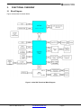
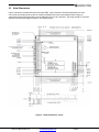
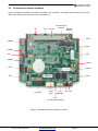
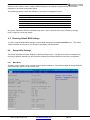
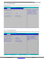
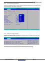
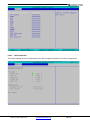
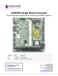
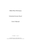
1
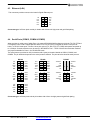
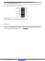
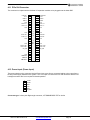
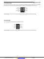
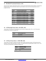
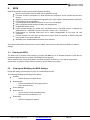
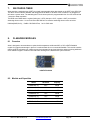
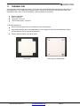
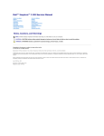
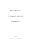
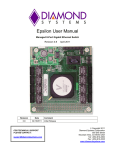
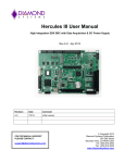
ATLAS Single Board Computer
PCI/104-Express SBC with Intel Atom N2800 Cedar Trail CPU
Revision
Date
Comments
Rev A.00
1/17/2014
Initial Release
Rev A.03
12/16/14
Updated Cable Kit, DK and SDK information
FOR TECHNICAL SUPPORT
PLEASE CONTACT:
[email protected]
Copyright 2014
Diamond Systems Corporation
555 Ellis Street
Mountain View, CA 94043 USA
Tel 1-650-810-2500
Fax 1-650-810-2525
www.diamondsystems.com
CONTENTS
Important Safe-Handling Information .....................................................................................................................4
1. Introduction .......................................................................................................................................................5
1.1 Atlas SBC Features .......................................................................................................................................6
1.2 Thermal Considerations ................................................................................................................................7
2. Functional Overview .........................................................................................................................................8
2.1 Block Diagram ...............................................................................................................................................8
2.2 Atlas Dimensions ...........................................................................................................................................9
2.3 Connector and Jumper Locations............................................................................................................... 10
2.3.1
Connector Summary .......................................................................................................................... 11
2.3.2
Configuration Jumper Summary ........................................................................................................ 11
3. Getting Started ............................................................................................................................................... 12
3.1 Introducing the Atlas Development Kit ....................................................................................................... 12
3.1.1
Atlas Cable Kit ................................................................................................................................... 13
3.2 System Setup ............................................................................................................................................. 14
3.2.1
Keyboard and Mouse ......................................................................................................................... 14
3.2.2
mSATA Flashdisk .............................................................................................................................. 14
3.2.3
Mass Storage Devices ....................................................................................................................... 14
3.2.4
Connecting Power .............................................................................................................................. 14
3.2.5
Display ............................................................................................................................................... 14
3.2.6
Installing Atlas in an Enclosure (optional) .......................................................................................... 14
3.3 Booting the System .................................................................................................................................... 15
3.3.1
BIOS Setup ........................................................................................................................................ 15
3.3.2
Operating System Drivers .................................................................................................................. 15
4. Interface Connector Details .......................................................................................................................... 16
4.1 External Battery (BAT) ................................................................................................................................ 16
4.2 SATA (SATA).............................................................................................................................................. 16
4.3 Ethernet (LAN) ............................................................................................................................................ 17
4.4 Serial Ports (COM12, COM34 & COM56) .................................................................................................. 17
4.5 USB 1-2 (USB12) ....................................................................................................................................... 18
4.6 USB 3-4 (USB34) ....................................................................................................................................... 18
4.7 Utility Signals (Utility) .................................................................................................................................. 19
4.8 LCD Backlight (LCD Backlight) ................................................................................................................... 19
4.9 LCD Panel (LVDS Interface) (LCD) ............................................................................................................ 20
4.10 PCI-104 ....................................................................................................................................................... 20
4.11 PCIe/104 Connector ................................................................................................................................... 21
4.12 Power Input (Power Input) .......................................................................................................................... 21
4.13 GPIO (GPIO) .............................................................................................................................................. 22
4.14 PCIe MiniCard / mSATA ............................................................................................................................. 22
4.15 Audio (Audio) .............................................................................................................................................. 23
4.16 VGA (VGA) ................................................................................................................................................. 23
5. Configuration Jumper Details ...................................................................................................................... 24
5.1 PCI-104 Voltage (JP1) ................................................................................................................................ 24
5.2 CMOS RAM Reset (JP2) ............................................................................................................................ 24
5.3 RS-422/485 Termination Resistors (JP4) ................................................................................................... 25
5.4 LCD Backlight Power Select – INV VSEL (JP5)......................................................................................... 25
5.5 LCD Panel Power Select – LVDS VSEL (JP6) ........................................................................................... 25
6. BIOS ................................................................................................................................................................ 26
6.1 Entering the BIOS ....................................................................................................................................... 26
6.2 Viewing and Modifying the BIOS Settings .................................................................................................. 26
6.3 Restoring Default BIOS Settings ................................................................................................................ 27
6.4 Setup Utility Settings .................................................................................................................................. 27
6.4.1
Main Menu ......................................................................................................................................... 27
6.4.2
Advanced Menu ................................................................................................................................. 28
6.4.3
Security Menu .................................................................................................................................... 33
6.4.4
Power Menu ....................................................................................................................................... 33
6.4.5
Boot Menu .......................................................................................................................................... 34
6.4.6
Exit Menu ........................................................................................................................................... 34
7. Watchdog Timer ............................................................................................................................................. 35
8. Flashdisk Modules ......................................................................................................................................... 35
8.1 Overview ..................................................................................................................................................... 35
Atlas User Manual Rev A.03
www.diamondsystems.com
Page 2
8.2 Models and Capacities ............................................................................................................................... 35
8.3 Features ...................................................................................................................................................... 36
8.4 Installation ................................................................................................................................................... 36
9. Power Supply ................................................................................................................................................. 36
10. Battery Backup............................................................................................................................................... 36
11. Thermal Pad ................................................................................................................................................... 37
12. Specifications................................................................................................................................................. 38
1.1 Operating System Support ......................................................................................................................... 38
1.2 Mechanical, Electrical, Environmental ........................................................................................................ 38
All trademarks are the property of their respective owners.
Atlas User Manual Rev A.03
www.diamondsystems.com
Page 3
IMPORTANT SAFE-HANDLING INFORMATION
WARNING: ESD-Sensitive Electronic Equipment!
Observe ESD-safe handling procedures when working with this product.
Always use this product in a properly grounded work area and wear
appropriate ESD-preventive clothing and/or accessories.
Always store this product in ESD-protective packaging when not in use.
Safe Handling Precautions
Atlas contains numerous I/O connectors that connect to sensitive electronic components. This creates many
opportunities for accidental damage during handling, installation and connection to other equipment. The list here
describes common causes of failure found on boards returned to Diamond Systems for repair. This information is
provided as a source of advice to help you prevent damaging your Diamond (or any vendor’s) embedded
computer boards.
ESD damage – This type of damage is almost impossible to detect, because there is no visual sign of failure or
damage. The symptom is that the board simply stops working, because some component becomes defective.
Usually the failure can be identified and the chip can be replaced.
To prevent ESD damage, always follow proper ESD-prevention practices when handling computer boards.
Damage during handling or storage – On some boards we have noticed physical damage from mishandling. A
common observation is that a screwdriver slipped while installing the board, causing a gouge in the PCB surface
and cutting signal traces or damaging components.
Another common observation is damaged board corners, indicating the board was dropped. This may or may not
cause damage to the circuitry, depending on what is near the corner. Most of our boards are designed with at
least 25 mils clearance between the board edge and any component pad, and ground / power planes are at least
20 mils from the edge to avoid possible shorting from this type of damage. However these design rules are not
sufficient to prevent damage in all situations.
A third cause of failure is when a metal screwdriver tip slips, or a screw drops onto the board while it is powered
on, causing a short between a power pin and a signal pin on a component. This can cause overvoltage / power
supply problems described below. To avoid this type of failure, only perform assembly operations when the
system is powered off.
Sometimes boards are stored in racks with slots that grip the edge of the board. This is a common practice for
board manufacturers. However our boards are generally very dense, and if the board has components very close
to the board edge, they can be damaged or even knocked off the board when the board tilts back in the rack.
Diamond recommends that all our boards be stored only in individual ESD-safe packaging. If multiple boards are
stored together, they should be contained in bins with dividers between boards. Do not pile boards on top of each
other or cram too many boards into a small location. This can cause damage to connector pins or fragile
components.
Power supply wired backwards – Our power supplies and boards are not designed to withstand a reverse
power supply connection. This will destroy each IC that is connected to the power supply. In this case the board
will most likely will be unrepairable and must be replaced. A chip destroyed by reverse power or by excessive
power will often have a visible hole on the top or show some deformation on the top surface due to vaporization
inside the package. Check twice before applying power!
Bent connector pins – This type of problem is often only a cosmetic issue and is easily fixed by bending the pins
back to their proper shape one at a time with needle-nose pliers. This situation can occur when pulling a ribbon
cable off of a pin header. Note: If the pins are bent too severely, bending them back can cause them to weaken
unacceptably or even break, and the connector must be replaced.
Atlas User Manual Rev A.03
www.diamondsystems.com
Page 4
1.
INTRODUCTION
Atlas is a high performance, highly integrated small form factor single board computer in the PCI/104-Express
form-factor. Atlas incorporates a wealth of standard PC-style I/O plus on-board digital I/O. Atlas provides
PCIe/104 I/O expansion by means of a new miniature, cost-effective expansion connector that supports most
PCIe/104 I/O modules. A PCIe MiniCard socket is available for additional add-on I/O. An integrated, bottommounted heatspreader dissipates heat efficiently to the system enclosure. This configuration leaves the SBC’s top
side free for easy access to memory, on-board I/O, and expansion sockets.
Key feature highlights include:
Compact, low-power, high-performance, stackable SBC
1.86GHz Intel N2800 CPU
2GB or 4GB soldered 64-bit DDR3 SDRAM
Comprehensive set of I/O interfaces:
- 4 USB 2.0 ports
- 4 RS-232/422/485 and 2 RS-232 serial ports
- 1 Gigabit Ethernet port
- 1 SATA port
- 18-bit LVDS LCD with dual independent displays
- VGA CRT
- ALC892 Codec based High Definition Audio with Stereo Line-Out, Stereo Line-In and Microphone
- USB keyboard and mouse support
- 8 programmable general purpose I/O lines
- Programmable watchdog timer
PCIe MiniCard socket auto-selects for either PCIe MiniCard module or mSATA flashdisk module
PC/104-Plus form factor (4.55” x 3.775”) with wings
Stackable I/O expansion flexibility
- PCI-104
- PCIe/104
-40°C to +75°C operating temperature
Atlas Models
Processor Type
ATLN2800-4G
Intel Atom N2800 CPU
1.86GHz
4GB DDR3 DRAM
ALTN2800-2G
Intel Atom N2800 CPU
1.86GHz
2GB DDR3 DRAM
Atlas User Manual Rev A.03
Processor Clock On-board RAM
www.diamondsystems.com
Page 5
1.1
Atlas SBC Features
Atlas is a compact, rugged, single board computer that features the Intel Atom N2800 Cedar Trail processor in the
PC/104-Plus form factor.
Functions
Intel Atom N2800 processor clocked at 1.86GHz
Cooling: Fanless design incorporates heatspreader and conduction cooling to the enclosure
Memory: 2GB or 4GB DDR3 memory soldered on board
Display options:
The video circuit consists of Intel’s GMA500 controller integrated into the processor. This circuit offers
dual independent simultaneous display support with both VGA and LVDS outputs. The video controller
shares main memory for its frame buffer.
- 18-bit LVDS flat panel interface supports dual independent displays; 1366 x 768 maximum resolution
- LVDS backlight power: +5V or +12V jumper selectable
- VGA CRT; 1280 x 1024 maximum resolution
4 USB 2.0 ports on headers
6 serial ports; Ports 1-4 supports TX, RX, RTS and CTS with RS-232/422/485 capability and Ports 5 & 6
support TX, RX, RTX and CTS RS-232 only
Networking: One Intel 82574IT based Gigabit Ethernet port on pin header, with on-board magnetics
Mass storage:
- One SATA port
- mSATA flashdisk mounting location supporting up to 64GB
Keyboard/Mouse: support for USB
Realtek ALC892 Codec based High Definition Audio with Stereo Line-Out, Stereo Line-In and
Microphone.
8 general purpose I/O lines
Programmable watchdog timer
Expansion socket: PCIe MiniCard full size auto-selects for either PCIe MiniCard module or mSATA
flashdisk module
Stackable I/O expansion buses: PCI-104 and PCIe/104
Input power: 5VDC ±5%
Power consumption: 7.53W idle
Operating temperature: -40°C to +75°C (-40°F to +167°F)
PC/104-Plus form factor with wings: mm x mm (4.550” x 3.775”)
Weight: 7.6oz (215.5 grams) with heatspreader
RoHS: Compliant
Atlas User Manual Rev A.03
www.diamondsystems.com
Page 6
LED Indicators
Atlas provides a set of LED indicators for various features as follows. All LEDS are located near their respective
function.
Power input:
Power on:
Ethernet:
Programmable LED:
Green LED when +5VDC is applied
Green LED when SBC is powered on
Green / yellow / orange; link, activity, and speed
Blue, connected to a GPIO line on the SCH3116 super I/O chip; this LED is off
during power-up and is turned on in the BIOS to indicate a successful system
BIOS startup.
PCIe MiniCard socket: 3 LEDs to support WWAN, WPAN, WLAN signals from the connector
Operating System Support
Windows Embedded Standard 7
Windows Embedded CE
Linux 2.6.xx
1.2
Thermal Considerations
o
o
All models of Atlas are specified for a -40 C to +75 C operating range, the temperature being measured at the
outside surface of the heatspreader. Diamond Systems provides a heatspreader attached to the Atlas single
board computer as a conductive cooled thermal layer. However, this heatspreader by itself does not constitute
the complete thermal solution necessary for any specific implementation, but provides a common interface
between the single board computer and the customer’s implementation-specific thermal solution.
o
The outside surface of the Atlas heatspreader must be kept at a temperature not to exceed +75 C. If your
environment causes the temperature on the outside surface of the heatspreader to exceed this temperature, you
are responsible for removing the additional heat from the system through either an additional passive thermal
solution or fan solution.
Atlas User Manual Rev A.03
www.diamondsystems.com
Page 7
2.
2.1
FUNCTIONAL OVERVIEW
Block Diagram
Figure 2 shows Atlas’ functional blocks.
Figure 2: Atlas SBC Functional Block Diagram
Atlas User Manual Rev A.03
www.diamondsystems.com
Page 8
2.2
Atlas Dimensions
Figure 3 shows the overall dimensions of the Atlas SBC. Atlas conforms to PC/104 specifications for the 4
corners and 4 mounting holes as well as component height limits on the top and bottom sides. Wings, or
extensions on the left and right sides, provide additional room for I/O connectors. The wings extend 0.5” past the
standard PC/104 board edges as shown in the drawing below.
.
Figure 3: Atlas Dimensions, inches
Atlas User Manual Rev A.03
www.diamondsystems.com
Page 9
2.3
Connector and Jumper Locations
Figure 4 illustrates the position of interface connectors, bus connectors, and jumper blocks located on the Atlas
SBC, which features PCI-104 and PCIe/104 stackable I/O.
JP1
JP2
PCIe MiniCard
/ mSATA External
PCI-104
Battery
GPIO
COM56
Utility
COM34
LAN
JP4
COM12
USB12
SATA
USB34
Audio
VGA
PCIe/104
Power
Input
JP5 JP6
LCD
Backlight
LCD
(on underside of board)
Figure 4: Atlas SBC Connector & Jumper Locations
Atlas User Manual Rev A.03
www.diamondsystems.com
Page 10
2.3.1
Connector Summary
The following table summarizes the functions of Atlas’s interface, utility, and power connectors. Signal functions
relating to all of Atlas’s interface connectors are discussed in greater detail in Section 4 of this document.
Diamond offers an optional Atlas Cable Kit (number CK-ATLAS-01), which provides mating cable assemblies for
most of Atlas’ I/O interface connectors.
2.3.2
Connector Function
Silkscreen Label
External Battery
SATA
Gigabit Ethernet
Serial Ports 1 & 2
Serial Ports 3 & 4
Serial Ports 5 & 6
USB Ports
Utility Signals
LCD Backlight
LCD (LVDS) Panel
PCIe/104
PCI-104
Power Input
GPIO
PCIe MiniCard / mSATA
Audio
VGA
BAT
SATA
LAN
COM12
COM34
COM56
USB12 & USB34
Utility
LCD Backlight
LCD
PCIe/104
PCI-104
Power Input
GPIO
PCIe MiniCard
Audio
VGA
Configuration Jumper Summary
The Atlas SBC contains jumper blocks for configuring the following features. The board also contains locations for
installation of 0-ohm resistors in place of all valid jumper positions for a rugged configuration. The 0-ohm resistors
are oriented and labeled in a way that provides easy understanding of their use and easy interpretation of their
settings.
Atlas’ configuration jumpers are listed below. Refer to Section 5 of this document for details regarding the
configuration of these jumper groups.
Jumper Group Function
Jumper Block
Array Size
PCI voltage (default: +5V)
JP1
1X3
CMOS RAM Reset (default: no clear)
JP2
1X3
Serial Port 1 RS-422/485 mode differential termination
resistor: Enable or Disable (default: Disable)
JP4
1X8
JP5
1X3
JP6
1X3
LCD backlight power: 5V or 12V (default: 5V)
(+12V provided through the input power connector)
LCD panel supply voltage: 3.3V or 5V (default: 3.3V)
-
Atlas User Manual Rev A.03
www.diamondsystems.com
Page 11
3.
GETTING STARTED
First-time Atlas SBC users normally receive the product as part of Diamond’s Atlas Development Kit, DK-ATLNLNX, which provides everything needed to ensure rapid application development. This section of the Atlas User
Manual covers basic hardware setup, power connection, system boot-up, and initial software configuration. After
Atlas is up and running, refer to the later sections of this manual for the detailed hardware and software reference
information needed to adapt the product to specific applications.
Important Safe-Handling Information
WARNING: ESD-Sensitive Electronic Equipment!
Observe ESD-safe handling procedures when working
with this product.
Always use this product in a properly grounded work area
and wear appropriate ESD-preventive clothing and/or
accessories.
Always store this product in ESD-protective packaging
when not in use.
Please refer to page 4 of this manual (“Important Safe-Handling Information”) for further
details.
3.1
Introducing the Atlas Development Kit
The Atlas Development Kit, DK-ATLN-LNX, provides everything required for Atlas-based rapid application
development. The table on the next page lists the boards, cables, and other items included. Each kit contains an
Atlas SBC, the Atlas Linux Software Development Kit, the Atlas Cable Kit, and a DVD with a Linux image.
Item
Diamond P/N
Description
1
ATLN2800-2G
Atlas SBC with 2GB DDR3 SDRAM on-board
2
8890673
16GB mSATA flashdisk with a bootable Linux image
3
6710673
DVD Linux image for Atlas SBC
4
CK-ATLAS-01
Atlas Cable Kit
5
PS-5V-04
5V AC Power Adapter
6
7480673
Atlas Quick Start Guide
7
DOC-PKG
Diamond Systems Document Package
Atlas User Manual Rev A.03
www.diamondsystems.com
Page 12
3.1.1
Atlas Cable Kit
The Atlas Cable Kit (number CK-ATLAS-01) provides convenient access to most of Atlas’s I/O features. The kit’s
cable assemblies are shown in the photo below, and identified in the table that follows.
Description
Diamond P/N
Connects to…
Item
Qty
1
1
Power input cable
6981074
Power Input
2
3
Dual serial cable
6981075
COM12, COM34 & COM56
3
1
HD Audio cable
6981076
Audio
4
1
Digital I/O cable
6981077
GPIO
5
1
Utility cable
6981078
Utility
6
1
Gigabit Ethernet cable to RJ45
6981080
LAN
7
2
Dual USB cable
6981082
USB12 & USB34
8
1
VGA cable
6981084
VGA
Note: On each interface cable, the end of the cable connector that has a red wire going to it
should be oriented toward the end of the board connector that is labeled “pin 1” (typically the pin
with a square pad on the PCB).
Atlas User Manual Rev A.03
www.diamondsystems.com
Page 13
3.2
System Setup
This section outlines a simple process for preparing Atlas for first-time operation using the Atlas Development Kit.
Additional details regarding Atlas’s interface functions and connections may be found in Section 4 of this
document.
3.2.1
Keyboard and Mouse
Atlas supports operation using a USB-based keyboard and mouse devices. Plug the USB keyboard connector
and USB mouse cable into the Atlas Cable Kit cable number 6981082 and the end of the cable into connector
USB12 on the Atlas SBC.
3.2.2
mSATA Flashdisk
Install the mSATA flashdisk, part number 8890673, onto the mSATA connector located on the top side of the
Atlas SBC. Remove the two screws from the mounting standoffs, insert the flashdisk into the mSATA connector,
re-installed the two screws into the standoffs securing the flashdisk to the Atlas SBC.
3.2.3
Mass Storage Devices
If you want to use an external SATA hard drive, connect a SATA hard drive to Atlas by connecting a SATA cable
to the SATA connector and then to the SATA drive. Atlas can operate with a combination of SATA and CD-ROM
drives, and can boot from either of them.
Caution! Be sure the PS-5V-04 AC power adapter is disconnected from
its AC power source prior to performing the following step.
3.2.4
Connecting Power
Connect cable 6981074 to the PS-5V-04 AC power adapter or an ATX power supply. Connect the other end of
the 6981074 cable to the Power Input connector on the Atlas SBC.
3.2.5
Display
Atlas provides interfaces for both LVDS flat panel displays and VGA output. Connect the VGA cable, 6981084,
between the VGA connector and a VGA-compatible display.
3.2.6
Installing Atlas in an Enclosure (optional)
Install the Atlas single board computer in an enclosure that has an appropriate mounting-hole pattern (2.8”
square).
Atlas’ heatspreader has four #6-32 threaded holes on 2.8” centers for mounting. Select four #6-32 threaded
screws of the proper length and head type to work with your enclosure. Allow a minimum of 0.25” and maximum
of 0.40” screw length for insertion into Atlas’s heatspreader. The total screw length will depend on the thickness
of your enclosure wall.
Atlas User Manual Rev A.03
www.diamondsystems.com
Page 14
3.3
Booting the System
Power-up the VGA video monitor. Then plug the PS-5V-04 AC power adapter to an AC outlet. Atlas should begin
its boot-up sequence immediately, as evidenced by BIOS messages on the connected VGA display. You can run
the BIOS Setup utility and proceed to install an operating system on the boot drive just as you would on a normal
desktop PC.
3.3.1
BIOS Setup
Atlas’s BIOS provides a wide range of configuration options. When you power up Atlas for the first time, you
should immediately enter the BIOS “Setup” utility in order to adjust BIOS settings to match your system’s
peripheral devices and other requirements, and to configure various other hardware and software parameters.
Options configurable via Setup typically include:
Number and type of mass storage devices
Boot device priority
Video display type and resolution
IDA, SATA, serial, and parallel interface modes and protocols
PCI and PnP configuration
Power management setup
Automatic power-up after LAN connection, RTC alarm, power resumption, etc.
System monitoring and security functions
3.3.2
Operating System Drivers
Using the operating system drivers provided on the CD in the Development Kit, create a bootable image of the
operating system, incorporating in any additional drivers desired for your system configuration. Atlas will boot and
run the operating system from the specified boot drive in the BIOS. Atlas should now be fully operational.
If you desire to run a different operating system, depending on the operating system to be installed, it may be
necessary to install software drivers for on-board interface controllers. Drivers for Windows Embedded Standard
7, Windows Embedded CE, and Linux 2.6, if required, are included on the Software and Documentation CD that
is included in the Atlas Development Kit.
Atlas User Manual Rev A.03
www.diamondsystems.com
Page 15
4.
INTERFACE CONNECTOR DETAILS
This section describes the functions associated with the Atlas SBC, bus expansion, utility, I/O interfaces, and
power connectors in greater detail. Section 3.1.1 contains a list of ready-to-use interface cables included in
Diamond’s Atlas Cable Kit.
4.1
External Battery (BAT)
Atlas has provision for an external battery connection via connector BAT, a two-pin connector.
A connector and jumper are provided to disable the on-board battery and enable use of an external battery
instead. The external battery voltage requirement is 3.3V +/-10%. The jumper also clears the CMOS RAM when it
is removed and no external battery is connected.
1
Ground
2
Battery+
Connector type: HIROSE, DF13-2P-1.25DSA(50)
4.2
SATA (SATA)
The SATA connector is an industry-standard right-angle connector. It is mounted flush with the edge of the board
so as to plug the SATA cable to an external hard drive.
1
Ground
2
Transmit+
3
Transmit-
4
Ground
5
Receive-
6
Receive+
7
Ground
Connector type: SAMTEC
Atlas User Manual Rev A.03
www.diamondsystems.com
Page 16
4.3
Ethernet (LAN)
This connector provides access to the board's Gigabit Ethernet port.
1
3
5
7
9
NC
DA+
DB+
DC+
DD+
2
4
6
8
10
Key
DADBDCDD-
Connector type: 2x5 2mm pitch vertical pin header with 4.0mm min high posts and gold flash plating
4.4
Serial Ports (COM12, COM34 & COM56)
Atlas provides six serial ports of which Ports 1-4 support RS-232/422/485 multiprotocol with the TX, RX, RTS and
CTS signals. Ports 5 and 6 support RS-232 with the TX, RX, RTS and CTS signals as shown in the pinouts
below. In RS-232 mode ports 1-4 offer 4 wires plus ground (TX, RX, RTS, CTS, GND) and operate at speeds up
to 115.2kbps. Console redirection can be set up in the BIOS for Port 1. TX/RX 121ohm line termination resistors
are jumper-selectable for Ports 1-4 in RS-422/485 mode.
The serial ports are provided on 2x5 pin headers with 2 ports per header labeled as COM12, COM34, and
COM56. The pin definition depends on the serial protocol selected. The pinouts below describe each protocol.
RS-232
RS-422
RS-485
TX1
RX1
GND
TX2
RX2
1
3
5
7
9
2
4
6
8
10
RTS1
CTS1
GND
RTS2
CTS2
TX1+
RX1+
GND
TX2+
RX2+
1
3
5
7
9
2
4
6
8
10
TX1RX1GND
TX2RX2-
TX1/RX1+
NC
GND
TX2/RX2+
NC
1
3
5
7
9
2
4
6
8
10
TX1/RX1NC
GND
TX2/RX2NC
TX3
RX3
GND
TX4
RX4
1
3
5
7
9
2
4
6
8
10
RTS3
CTS3
GND
RTS4
CTS4
TX3+
RX3+
GND
TX4+
RX4+
1
3
5
7
9
2
4
6
8
10
TX3RX3GND
TX4RX4-
TX3/RX3+
NC
GND
TX4/RX4+
NC
1
3
5
7
9
2
4
6
8
10
TX3/RX3NC
GND
TX4/RX4NC
TX5
RX5
GND
TX6
RX6
1
3
5
7
9
2
4
6
8
10
RTS5
CTS5
GND
RTS6
CTS6
Connector type: 2x5 2mm pitch vertical pin headers with 4.0mm min high posts and gold flash plating
Atlas User Manual Rev A.03
www.diamondsystems.com
Page 17
4.5
USB 1-2 (USB12)
This connector provides access to two of the board's four USB 2.0 ports, USB1 and USB2. The shield pin is tied
to system ground.
NC (Key)
USB2 GND
USB2 Data+
USB2 DataUSB2 Pwr
1
3
5
7
9
2
4
6
8
10
Shield
USB1 GND
USB1 Data+
USB1 DataUSB1 Pwr
Connector type: 2x5 2mm pitch vertical pin headers with 4.0mm min high posts and gold flash plating
4.6
USB 3-4 (USB34)
This connector provides access to two of the board's four USB 2.0 ports, USB3 and USB4. The shield pin is tied
to system ground.
NC (Key)
USB4 GND
USB4 Data+
USB4 DataUSB4 Pwr
1
3
5
7
9
2
4
6
8
10
Shield
USB3 GND
USB3 Data+
USB3 DataUSB3 Pwr
Connector type: 2x5 2mm pitch vertical pin headers with 4.0mm min high posts and gold flash plating
Atlas User Manual Rev A.03
www.diamondsystems.com
Page 18
4.7
Utility Signals (Utility)
This connector provides utility signals and LED indicator signals for Atlas as follows.
Gnd
Gnd
NC
+5V
+3.3V
+3.3V
+3.3V
+3.3V
Speaker
Power LED
LAN Link 100
LAN Link 1000
LAN Activity
1
3
5
7
9
11
13
15
2
4
6
8
10
12
14
16
ResetPWRBTNNC
Speaker
Power On LED
LAN Activity LED
LAN Link 100 LED
Lan Link 1000 LED
PC speaker. Connect a speaker between this pin and +5V.
Referenced to +3.3V. Does not require any external series resistor. Connect LED
directly between this pin and +3.3V pin.
Illuminated for 100Mbps Ethernet operation
Illuminated for 1000Mbps Ethernet operation
Illuminated during any Ethernet activity
Reset-
Connection between this pin and ground will generate a system reset condition. It is
intended for use with a momentary switch.
PWRBTN-
A momentary connection between this pin and ground will power-up/power-down the
board.
Connector type: 2x8 2mm pitch vertical pin header with 4.0mm min high posts and gold flash plating
4.8
LCD Backlight (LCD Backlight)
This connector provides the backlight power and control for the optional LCD panel.
Note: If needed, +12V must be provided on the input power connector.
1
Power +5V/+12V, jumper selectable (default +5V), fused
2
Power +5V/+12V, jumper selectable (default +5V), fused
3
Ground
4
Ground
5
Enable (GPIO output), 0 = off, open circuit = on
6
Brightness, 0-5VDC variable; 0V = max, 5V = min
The brightness control for the LCD backlight has a weak pull-down resistor to ensure maximum brightness when it
is not connected externally. Brightness may be controlled by a GPIO pin on the CPU or embedded microcontroller
or by pin 6 on this connector. A jumper selects the source of the brightness signal to this pin.
Connector type: Molex 53261-0671 or equivalent
Mating connector: Socket: Molex 51021-0600 or equivalent
Terminals: Molex 50058 / 50079 series or equivalent
Atlas User Manual Rev A.03
www.diamondsystems.com
Page 19
4.9
LCD Panel (LVDS Interface) (LCD)
This connector is mounted on the top side of Atlas. It provides connection to an LVDS LCD display. The LCD
panel power is jumper selectable for 3.3V (default) or 5V.
LVDS_DATA3+
SCAN_DIRECTION
GND
LVDS_CLKLVDS_DATA2+
GND
LVDS_DATA1LVDS_DATA0+
GND
VCC_LCD, fused
1
3
5
7
9
11
13
15
17
19
2
4
6
8
10
12
14
16
18
20
LVDS_DATA3LVDS_MAP
LVDS_CLK+
GND
LVDS_DATA2LVDS_DATA1+
GND
LVDS_DATA0GND
VCC_LCD, fused
Connector type: Hirose part number DF14-20P-1.25H(20) or equivalent
Cable-mount socket: Hirose part number DF14-20S-1.25C or equivalent
4.10 PCI-104
The PCI-104 (PCI) bus connector is provided on the top side to enable the mounting of additional I/O boards. The
PCI connector is non-stack through (top side only) and is located in the standard PCI-104 location. Its pinout is
as defined in the PC/104-Plus specification available on www.pc104.org. The VIO pins are jumper-selected and
are protected with a polyswitch resettable fuse.
Atlas User Manual Rev A.03
www.diamondsystems.com
Page 20
4.11 PCIe/104 Connector
This connector is implemented to facilitate I/O expansion modules to be plugged onto the Atlas SBC.
1
3
5
7
9
11
13
15
17
19
21
23
25
27
29
31
33
35
37
39
41
43
45
47
49
51
USB-OC+3.3V
USB 5+
USB 5Gnd
PCIe 4 T+
PCIe 4 TGnd
Gnd
PCIe 1 R+
PCIe 1 RGnd
Gnd
PCIe 4 Clk+
PCIe 4 Clk+5V_SB
Gnd
SMB Data
SMB Clk
SMB Alert-
+
5
V
T
A
B
2
4
6
8
10
12
14
16
18
20
22
24
26
28
30
32
34
36
38
40
42
44
46
48
50
52
PCIe Reset+3.3V
USB 6+
USB 6Gnd
PCIe 1 T+
PCIe 1 TGnd
Gnd
PCIe 0 R+
PCIe 0 RGnd
Gnd
PCIe 1 Clk+
PCIe 1 Clk+5V_SB
4.12 Power Input (Power Input)
The power signals on the connector labeled Power Input come from a connector leading to the output from a
DC/DC power supply installed in the system. The +12V input is routed to the PCI/104 connector and the LCD
backlight connector but is not required for board operation.
1
2
3
4
5
6
+5VDC
+5VDC
GND
+12V
GND
Ext_Batt
Connector type: 2.0mm pitch Right angle connector, JST SM06B-PASS-TBT or similar
Atlas User Manual Rev A.03
www.diamondsystems.com
Page 21
4.13 GPIO (GPIO)
Atlas provides eight general purpose I/O lines on a pin header derived from the NM10 chipset. These I/O lines are
protected with ESD devices to minimize potential damage to the NM10 from environmental conditions. The GPIO
connector provides the digital IO signals as shown below.
GPIO0
GPIO2
GPIO4
GPIO6
+3.3V (fused)
1
3
5
7
9
2
4
6
8
10
GPIO1
GPIO3
GPIO5
GPIO7
Ground
Connector type: 2x5 2mm pitch vertical pin header with 4.0mm min high posts and gold flash plating
4.14 PCIe MiniCard / mSATA
This is a shared socket for either full sized PCIe MiniCards or mSATA storage modules. The PCIe MiniCard
socket provides the facility to plug-in third party Mini-PCIe cards such as WiFi, Bluetooth, etc. The pinout below
shows both PCIe MiniCard and mSATA pinouts. The signals in bold are selected automatically based on the type
of card inserted into the socket.
PCIe MiniCard
ClkreqGnd
PCIe ClkPCIe Clk+
Gnd
mSATA
ClkreqGnd
PCIe ClkPCIe Clk+
Gnd
Gnd
PCIe RXPCIe RX+
Gnd
Gnd
PCIe TXPCIe TX+
Gnd
Gnd
+3.3V
+3.3V
PCIe Select-
Gnd
SATA 0 RXSATA 0 RX+
Gnd
Gnd
SATA 0 TXSATA 0 TX+
Gnd
Gnd
+3.3V
+3.3V
Pull-up to +3.3V
Pull-up to +3.3V
mSATA / PCIe MiniCard
1
2
3
4
5
6
7
8
9
10
11
12
13
14
15
16
KEY
17
18
19
20
21
22
23
24
25
26
27
28
29
30
31
32
33
34
35
36
37
38
39
40
41
42
43
44
45
46
47
48
49
50
51
52
+3.3V
Gnd
+1.5V
Gnd
DisablePCIe Reset+3.3V
Gnd
+1.5V
SMB Clk
SMB Data
Gnd
USB 4USB 4+
Gnd
WWAN LEDWLAN LEDWPAN LED+1.5V
Gnd
+3.3V
Connector type: JAE MM60-52B1-E1-R650
Atlas User Manual Rev A.03
www.diamondsystems.com
Page 22
4.15 Audio (Audio)
The Audio connector has the Stereo Line-In, Stereo Line-Out and Mono Microphone signals from the ALC892
HD-Audio Codec. External speakers, headphones and a microphone can be interfaced to this connector.
LineOut – L
GND_AUDIO
LineIn – L
GND_AUDIO
MIC_L
1
3
5
7
9
2
4
6
8
10
LineOut – R
GND_AUDIO
LineIn – R
GND_AUDIO
MIC_R
Connector type: 2x5 2mm pitch vertical pin header with 4.0mm min high posts and gold flash plating
4.16 VGA (VGA)
The VGA connector provides support for standard VGA CRTs.
Red
Green
Blue
HSync
VSync
1
3
5
7
9
2
4
6
8
10
Ground
Key
Ground
DDC-Data
DDC-Clock
Connector type: 2x5 2mm pitch vertical pin header with 4.0mm min high posts and gold flash plating
Atlas User Manual Rev A.03
www.diamondsystems.com
Page 23
5.
CONFIGURATION JUMPER DETAILS
This section explains the use of the jumper options on the Atlas SBC.
Atlas contains jumper blocks for configuring the following features. The board also contains locations for
installation of 0-ohm resistors in place of all valid jumper positions for a rugged configuration. The 0-ohm resistors
are oriented and labeled in a way that provides easy understanding of their use and easy interpretation of their
settings.
Jumper Group Function
Jumper Block
PCI-104 VIO voltage (default: +5V)
JP1
1X3
CMOS RAM Reset (default: no clear)
JP2
1X3
Serial Port RS-422/485 mode differential termination
resistors: Enable or Disable (default: Disable)
JP4
1X8
JP5
1X3
JP6
1X3
LCD backlight power: 5V or 12V (default: 5V)
(+12V provided through the input power connector)
LCD panel supply voltage: 3.3V or 5V (default: 3.3V)
5.1
Array Size
PCI-104 Voltage (JP1)
JP1 enables selection of 3.3V or 5V for VIO on the PCI-104 connector. This power is protected with a polyswitch
resettable fuse.
5.2
Setting
V10 Power
1-2
+3.3V (default)
2-3
+5V
CMOS RAM Reset (JP2)
JP2 provides for a reset of the BIOS settings and CMOS RAM on power up. The jumper connects both on-board
and external backup batteries to the backup power connection for the CMOS settings. Using the jumper resets
the settings to their programmed default values and also resets the on-board real-time clock.
To reset the settings, turn the power off, move the jumper to the reset position, turn power on and booth the
system.
Setting
Reset
1-2
No reset on power on (default)
2-3
CMOS reset at power on
Atlas User Manual Rev A.03
www.diamondsystems.com
Page 24
5.3
RS-422/485 Termination Resistors (JP4)
All the serial ports feature independent selection of protocol (RS-232/422/485) and IRQ in BIOS. For RS-422 and
RS-485 modes, 120 ohm termination resistors may be enabled on the receiver lines with jumpers found on
jumper block JP4.
5.4
Setting
Termination Enable/Disable
Protocol
Open
Termination Disable (default)
RS-233
1–2
COM1 RS-485 Termination Enable
RS-485
3–4
COM1 RS-422 Termination Enable
RS-422
5–6
COM2 RS-485 Termination Enable
RS-485
7–8
COM2 RS-422 Termination Enable
RS-422
9 – 10
COM3 RS-485 Termination Enable
RS-485
11 – 12
COM3 RS-422 Termination Enable
RS-422
13 – 14
COM4 RS-485 Termination Enable
RS-485
15 – 16
COM4 RS-422 Termination Enable
RS-422
LCD Backlight Power Select – INV VSEL (JP5)
Jumper block JP5 selects the LCD backlight inverter DC power voltage as either +5V or +12V. This power is
protected with a polyswitch resettable fuse.
5.5
Setting
LCD Backlight Power
1–2
+5V (default)
2–3
+12V
LCD Panel Power Select – LVDS VSEL (JP6)
Jumper block JP6 must be configured according to input voltage required by the type of LCD panel that will be
attached to Atlas’s LCD panel interface connector. The jumper sets the LCD panel power as either +3.3V or +5V.
This power is protected with a polyswitch resettable fuse.
Atlas User Manual Rev A.03
Setting
LCD Panel Voltage
1-2
+3.3V (default)
2-3
+5V
www.diamondsystems.com
Page 25
6.
BIOS
Atlas’ BIOS provides access to many valuable features including:
Boot from LAN (PXE) as well as USB, SATA, and mSATA ports
Free boot sequence configuration to allow different boot sequences as first, second and third boot
devices.
Support for various LCD configurations supported by the video chipset ( default should be 1024x768 )
LCD brightness control adjustment
Console (display and keyboard) redirection to one or more COM ports
DSC-configurable default settings in battery-less configurations
Customizable splash screen
POST message displays the board name and BIOS version. The BIOS version is displayed as
“Major.Minor-rev – Date Built” format. For example “Version 1.01 – 10/12/2012”.
Enable/disable for individual COM ports and a master enable/disable for the super I/O chip
completely.
Protocol selection for each of the 6 COM ports to select serial port protocol on SP336 using DIO
lines. Default for all 6 ports is RS-232.
Watchdog timer enable/disable and timeout period selection.
The following instructions describe how to enter the BIOS, set up features, and restore the BIOS to its default
settings.
6.1
Entering the BIOS
The BIOS may be entered during startup by pressing the ESC key on an attached keyboard. Press the key
repeatedly right after power-on or reset until the BIOS screen appears.
After a certain amount of time during startup, the BIOS will ignore the ESC key. If you wait too long and the
system does not respond, simply reset the system (or power down) and try again.
6.2
Viewing and Modifying the BIOS Settings
During SBC startup, press function key ESC to enter BIOS setup mode.
The main page displays the following menu options:
Continue
o Selects the first boot option device
Boot Manager
o Lists all the bootable EFI and legacy devices
o Select the boot device
Device Manager
Boot From File
o Lists all the FAT format message devices
o Select one EFI formatted file to run
Setup Utility
o Offers full configuration options
Atlas User Manual Rev A.03
www.diamondsystems.com
Page 26
Select the menu option to view or modify the BIOS settings for the desired configuration area. The screens
displayed for each area are described, below.
The following keyboard controls are available on any page for navigating the screen.
Key
Esc
up-/down-arrow
left-/right-arrow
plus/minus symbols (+/-)
Enter
Function
Exit current screen, return to previous screen
Select setup item
Select menu item
Change values
Select item / Execute command
At any time, select Save & Exit to exit BIOS setup mode. Use the up/down arrow keys, followed by carriage
return, to apply one of the exit actions.
6.3
Restoring Default BIOS Settings
In order to load the default BIOS settings, enter the BIOS settings and select Save and Exit menu. Then select
Restore Defaults, and save/exit. This will restore the BIOS to the default state.
6.4
Setup Utility Settings
This section describes the screen displays for the Setup Utility section. The data in the fields are examples only
and may be different depending on future product releases from Diamond Systems or the user’s configuration.
6.4.1
Main Menu
The Main menu provides a quick overview of basic system information. It provides the ability to change the BIOS
display language, system time and system date.
Atlas User Manual Rev A.03
www.diamondsystems.com
Page 27
6.4.2
Advanced Menu
The Advanced menu allows the user to configure advanced system settings such as super I/O, peripheral, USB
and console redirection settings.
6.4.2.1
Super I/O Configuration Menu
Available from the Advanced menu, the Super I/O menu allows the user to enable or disable the Super I/O chip,
enable and set addresses for each serial port, and set the watchdog timer.
6.4.2.2
Peripheral Configuration Menu
Available from the Advanced menu, the Peripheral Configuration menu provides for configuration of the digital I/O
lines. Selecting the GPIO Configuration sub menu provides line-by-line configurability.
Atlas User Manual Rev A.03
www.diamondsystems.com
Page 28
6.4.2.3
IDE Configuration Menu
Available from the Advanced menu, the IDE Configuration menu allows the user to select the IDE controller and
hard disk drive type.
6.4.2.4
Video Configuration Menu
Available from the Advanced menu, the Video Configuration menu allows the user to configure the video output
including the display type and resolution.
Atlas User Manual Rev A.03
www.diamondsystems.com
Page 29
6.4.2.5
USB Configuration Menu
Available from the Advanced menu, the USB Configuration menu allows the user to configure each USB port.
6.4.2.6
ACPI Table/Features Control Menu
Available from the Advanced menu, the ACPI Table/Features Control menu allows the user to enable or disable
the ACPI features.
Atlas User Manual Rev A.03
www.diamondsystems.com
Page 30
6.4.2.7
Console Redirection Setup Menu
Available from the Advanced menu, the Console Redirection Setup menu allows the user to set up and configure
console redirection for remote access via a serial port.
6.4.2.8
PCI Express Configuration Menu
Available from the Advanced menu, the PCI Express Configuration Setup menu allows the user to set up and
configure console redirection for remote access.
The detailed screen on the next page shows the PCIe configuration options for each port.
Atlas User Manual Rev A.03
www.diamondsystems.com
Page 31
6.4.2.9
Hardware Monitor
This screen displays the current health status of the SBC including temperature and various voltage levels.
Atlas User Manual Rev A.03
www.diamondsystems.com
Page 32
6.4.3
Security Menu
The Security Menu provides configuration for the system’s password settings.
6.4.4
Power Menu
The Power Menu provides configuration options used to manage the consumption of system power.
Atlas User Manual Rev A.03
www.diamondsystems.com
Page 33
6.4.5
Boot Menu
The Boot Menu provides configuration and sequencing of various boot devices.
6.4.6
Exit Menu
The Exit Menu provides various options for saving and exiting, and for loading default settings.
Atlas User Manual Rev A.03
www.diamondsystems.com
Page 34
7.
WATCHDOG TIMER
Atlas provides a watchdog timer (WDT) circuit with programmable delay time based on the WDT in the SCH3116.
The WDT can be enabled, disabled, and retriggered in the BIOS. If the WDT times out before it is retriggered, it
will cause a system reset. The watchdog timer circuit timeout period is programmable from 0 to 255 seconds with
1 second or better resolution.
The BIOS uses CMOS bank 1 register (index port = 0x70, data port = 0x71, register = 0x6F) to record the
watchdog timeout value. A user could send SW SMI 0x13 to reset the watchdog timeout value as below:
IOWrite8(0xB2, 0x13); //0xB2 = SW SMI IO Port, 0x13 = SMI value
8.
8.1
FLASHDISK MODULES
Overview
Atlas is designed to accommodate an optional wide-temperature solid-state MLC or SLC mSATA flashdisk
module for rugged mass storage in place of a notebook hard drive or commercial flashdisk. This module contains
8GB to 64GB of solid-state non-volatile memory that operates like any hard disk drive without requiring additional
driver software support. It features automatic wear leveling and 1,000,000 write cycles minimum.
mSATA Flashdisk
8.2
Models and Capacities
Atlas User Manual Rev A.03
Model
MLC/SLC
Capacity
FDMM-64G-XT
MLC
64GB
FDMM-32G-XT
MLC
32GB
FDMM-16G-XT
MLC
16GB
FDMS-64G-XT
SLC
64GB
FDMS-32G-XT
SLC
32GB
FDMS-16G-XT
SLC
16GB
FDMS-8G-XT
SLC
8GB
www.diamondsystems.com
Page 35
8.3
Features
The flashdisk module works just like a disk drive and requires no drivers. It provides high-speed nonvolatile mass
storage in capacities of 8GB to 64GB. It is available in both MLC and SLC versions. The flashdisk plugs in to the
PCIe MiniCard / mSATA socket and is held in place with two spacers and screws (included). It operates over the
full -40ºC to +85ºC operating temperature range.
mSATA flashdisk features:
mSATA compatible interface
Sustained read performance of 30MB/s
Sustained write performance of 20MB/s
Implements dynamic wear-leveling algorithms to substantially increase longevity
BCH (6/12 bit) Error Detection Code/Error Correction Code (EDC/ECC0)
Intrinsic data integrity after power loss
Wear leveling algorithm provides more reliable data storage over time
Write protection setting by jumper for prevention of data overwrites
Supports boot function for Windows Embedded Standard 7, Windows Embedded CE, and Linux
Low power consumption, typical 110mA when active and 0.45mA in sleep mode
-40ºC to +85ºC operation
RoHS compliant
8.4
Installation
Installing an mSATA flashdisk module on Atlas is straightforward using the following steps.
1. Ensure power is disconnected from Atlas.
2. Remove the two screws from the standoffs located across from the PCIe MiniCard / mSATA
connector.
3. Align the flashdisk at a 45 degree upward slant with its edge finger edge aligned with the pins on the
connector, the memory chips on the top side, and the mounting holes align above the standoffs.
4. Slide the flashdisk into the connector and downward onto the standoffs.
5. Reinstall the two screws, securing the flashdisk module to Atlas.
9.
POWER SUPPLY
Atlas requires only +5VDC input voltage as per the PC/104 Specification. It supports routing of +12VDC from the
input power connector to various other connectors. The +5V supply comes from an external source via the Power
Input connector. All the other on-board supply voltages are derived from the +5VDC main input.
A +5VDC/+12VDC source must be connected to the Atlas SBC power connector. An ATX power supply can be
used to power the Atlas SBC. The +5VDC/+12VDC power source is interfaced to the board on the locking
connector labeled Power Input. The +5VDC is used by the Atlas SBC for all its power subsystems. The +12VDC
is used for the LVDS panel backlight inverter.
10.
BATTERY BACKUP
Atlas includes a backup battery for CMOS RAM and real-time clock backup. The 3.0V lithium battery is mounted
on the board to provide the RTC voltage to the CMOS/RTC. The battery is a CR-2354/GUN or equivalent type
o
with 3 pins. The battery provides minimum 5 years lifetime based on Ta=25 C and 0% power duty cycle. The
battery is soldered on the top side of the board. The battery is an integrated unit with soldered terminals and
soldered on the top of the board. It is not a field replaceable battery. Connector BAT is provided to enable the
use of an external battery.
Atlas User Manual Rev A.03
www.diamondsystems.com
Page 36
11.
THERMAL PAD
A thermal pad is included with every Atlas. It is the same size as the heatspreader and attaches to the bottom of
the heatspreader, but is shipped loose with the product. Customers can choose to affix the thermal pad or not
depending on their needs. The specifications for the thermal pad are as follows.
Material: 3M 5590H
Color: Light Grey
Thickness: 0.5/1.0 mm
Thermal Conductivity: 3.0 W/m-K
To affix the thermal pad:
Remove the clear plastic film from the adhesive side of thermal pad
Align the thermal pad above the heatspreader so all four edges are flush with the heatspreader edges
and the adhesive side is facing the heatspreader
Press to attach as shown in the photo below
Thermal pad on heatspreader
Thermal pad
Atlas User Manual Rev A.03
www.diamondsystems.com
Page 37
12.
SPECIFICATIONS
1.86GHz Intel Atom N2800 Cedar Trail CPU
CPU Passmark: 653
Cooling : Heatspreader, fanless
2GB or 4GB 64-bit DDR3 memory soldered on board
Display options:
o
18-bit LVDS flat panel interface with support for dual independent displays; 1366 x 768 maximum
display size
o
LVDS backlight power: +5V or +12V jumper selectable
o
VGA CRT, 1280 x 1024 maximum display size
Keyboard/Mouse USB
USB: 4 USB 2.0 ports on headers
Serial: 6 serial ports; Ports 1-4 supports TX, RX, RTS and CTS with RS-232/422/485 capability and Ports
5 & 6 support TX, RX, RTX and CTS RS-232 only
Networking: One Intel 82574IT based Gigabit Ethernet port on pin header, with on-board magnetics
Mass storage:
o
1 SATA port
o
mSATA flashdisk mounting location
ALC892 Codec based High Definition Audio with Stereo Line-Out, Stereo Line-In and Microphone.
8 GPIOs from the PIC Microcontroller
Programmable watchdog timer
PCIe MiniCard / mSATA shared socket
PCI-104 and PCIe/104 stackable expansion connectors
1.1 Operating System Support
Windows Embedded Standard 7
Windows CE
Linux 2.6.xx
1.2 Mechanical, Electrical, Environmental
PC/104-Plus form factor
Heatspreader, for the processor and chipset on the bottom PCB surface, with 2.8” x 2.8” mounting pattern
-40°C to +75°C ambient operating temperature without a fan
Power input requirements: +5VDC +/- 5%
Power consumption: 7.53W idle
Optional +12VDC for the LCD backlight ONLY. No on-board circuits can depend on +12VDC.
Dimensions: 4.55" x 3.775" x 0.9” (125mm x 96mm x 23mm)
Weight: 7.6oz (215.5 grams) with heatspreader
Atlas User Manual Rev A.03
www.diamondsystems.com
Page 38