1
BreezeACCESS® VL and BreezeNET®
B Device Driver
AlvariSTAR™ User Manual
Software Version 3.0
October 2005
P/N: 214186
Legal Rights
Legal Rights
© Copyright 2005 Alvarion Ltd. All rights reserved.
The material contained herein is proprietary, privileged, and confidential and
owned by Alvarion or its third party licensors. No disclosure thereof shall be made
to third parties without the express written permission of Alvarion Ltd.
Alvarion Ltd. reserves the right to alter the equipment specifications and
descriptions in this publication without prior notice. No part of this publication
shall be deemed to be part of any contract or warranty unless specifically
incorporated by reference into such contract or warranty.
Trade Names
Alvarion®, BreezeCOM®, WALKair®, WALKnet®, BreezeNET®, BreezeACCESS®,
BreezeMANAGE™, BreezeLINK®, BreezeCONFIG™, BreezeMAX™, AlvariSTAR™,
MGW™, eMGW™, WAVEXpress™, MicroXpress™, WAVEXchange™, WAVEView™,
GSM Network in a Box and TurboWAVE™ and/or other products and/or services
referenced here in are either registered trademarks, trademarks or service marks
of Alvarion Ltd.
All other names are or may be the trademarks of their respective owners.
Statement of Conditions
The information contained in this manual is subject to change without notice.
Alvarion Ltd. shall not be liable for errors contained herein or for incidental or
consequential damages in connection with the furnishing, performance, or use of
this manual or equipment supplied with it.
Warranties and Disclaimers
All Alvarion Ltd. ("Alvarion") products purchased from Alvarion or through any of
Alvarion's authorized resellers are subject to the following warranty and product
liability terms and conditions.
Exclusive Warranty
With respect to the Software, Alvarion warrants the correct functionality
according to the attached documentation, for a period of fourteen (14) month from
invoice date (the "Warranty Period"). During the Warranty Period, Alvarion may
release to its Customers software updates, which include additional performance
improvements and/or bug fixes, upon availability (the "Warranty"). Bug fixes,
temporary patches and/or workarounds may be supplied as Software updates.
ii
BreezeACCESS VL and BreezeNET B Device Driver
Legal Rights
Additional hardware, if required, to install or use Software updates must be
purchased by the Customer. Alvarion will be obligated to support solely the two (2)
most recent Software major releases.
ALVARION SHALL NOT BE LIABLE UNDER THIS WARRANTY IF ITS TESTING
AND EXAMINATION DISCLOSE THAT THE ALLEGED DEFECT IN THE PRODUCT
DOES NOT EXIST OR WAS CAUSED BY PURCHASER'S OR ANY THIRD
PERSON'S MISUSE, NEGLIGENCE, IMPROPER INSTALLATION OR IMPROPER
TESTING, UNAUTHORIZED ATTEMPTS TO REPAIR, OR ANY OTHER CAUSE
BEYOND THE RANGE OF THE INTENDED USE, OR BY ACCIDENT, FIRE,
LIGHTNING OR OTHER HAZARD.
Disclaimer
(a) The Software is sold on an "AS IS" basis. Alvarion, its affiliates or its licensors
MAKE NO WARRANTIES, WHATSOEVER, WHETHER EXPRESS OR IMPLIED,
WITH RESPECT TO THE SOFTWARE AND THE ACCOMPANYING
DOCUMENTATION. ALVARION SPECIFICALLY DISCLAIMS ALL IMPLIED
WARRANTIES OF MERCHANTABILITY AND FITNESS FOR A PARTICULAR
PURPOSE AND NON-INFRINGEMENT WITH RESPECT TO THE SOFTWARE.
UNITS OF PRODUCT (INCLUDING ALL THE SOFTWARE) DELIVERED TO
PURCHASER HEREUNDER ARE NOT FAULT-TOLERANT AND ARE NOT
DESIGNED, MANUFACTURED OR INTENDED FOR USE OR RESALE IN
APPLICATIONS WHERE THE FAILURE, MALFUNCTION OR INACCURACY OF
PRODUCTS CARRIES A RISK OF DEATH OR BODILY INJURY OR SEVERE
PHYSICAL OR ENVIRONMENTAL DAMAGE ("HIGH RISK ACTIVITIES"). HIGH
RISK ACTIVITIES MAY INCLUDE, BUT ARE NOT LIMITED TO, USE AS PART OF
ON-LINE CONTROL SYSTEMS IN HAZARDOUS ENVIRONMENTS REQUIRING
FAIL-SAFE PERFORMANCE, SUCH AS IN THE OPERATION OF NUCLEAR
FACILITIES, AIRCRAFT NAVIGATION OR COMMUNICATION SYSTEMS, AIR
TRAFFIC CONTROL, LIFE SUPPORT MACHINES, WEAPONS SYSTEMS OR
OTHER APPLICATIONS REPRESENTING A SIMILAR DEGREE OF POTENTIAL
HAZARD. ALVARION SPECIFICALLY DISCLAIMS ANY EXPRESS OR IMPLIED
WARRANTY OF FITNESS FOR HIGH RISK ACTIVITIES.
(b) PURCHASER'S SOLE REMEDY FOR BREACH OF THE EXPRESS
WARRANTIES ABOVE SHALL BE REPLACEMENT OR REFUND OF THE
PURCHASE PRICE AS SPECIFIED ABOVE, AT ALVARION'S OPTION. TO THE
FULLEST EXTENT ALLOWED BY LAW, THE WARRANTIES AND REMEDIES SET
FORTH IN THIS AGREEMENT ARE EXCLUSIVE AND IN LIEU OF ALL OTHER
WARRANTIES OR CONDITIONS, EXPRESS OR IMPLIED, EITHER IN FACT OR BY
OPERATION OF LAW, STATUTORY OR OTHERWISE, INCLUDING BUT NOT
LIMITED TO WARRANTIES, TERMS OR CONDITIONS OF MERCHANTABILITY,
FITNESS FOR A PARTICULAR PURPOSE, SATISFACTORY QUALITY,
User Manual
iii
Legal Rights
CORRESPONDENCE WITH DESCRIPTION, NON-INFRINGEMENT, AND
ACCURACY OF INFORMATION GENERATED. ALL OF WHICH ARE EXPRESSLY
DISCLAIMED. ALVARION' WARRANTIES HEREIN RUN ONLY TO PURCHASER,
AND ARE NOT EXTENDED TO ANY THIRD PARTIES. ALVARION NEITHER
ASSUMES NOR AUTHORIZES ANY OTHER PERSON TO ASSUME FOR IT ANY
OTHER LIABILITY IN CONNECTION WITH THE SALE, INSTALLATION,
MAINTENANCE OR USE OF ITS PRODUCTS.
Limitation of Liability
(a) ALVARION SHALL NOT BE LIABLE TO THE PURCHASER OR TO ANY THIRD
PARTY, FOR ANY LOSS OF PROFITS, LOSS OF USE, INTERRUPTION OF
BUSINESS OR FOR ANY INDIRECT, SPECIAL, INCIDENTAL, PUNITIVE OR
CONSEQUENTIAL DAMAGES OF ANY KIND, WHETHER ARISING UNDER
BREACH OF CONTRACT, TORT (INCLUDING NEGLIGENCE), STRICT LIABILITY
OR OTHERWISE AND WHETHER BASED ON THIS AGREEMENT OR
OTHERWISE, EVEN IF ADVISED OF THE POSSIBILITY OF SUCH DAMAGES.
(b) TO THE EXTENT PERMITTED BY APPLICABLE LAW, IN NO EVENT SHALL
THE LIABILITY FOR DAMAGES HEREUNDER OF ALVARION OR ITS EMPLOYEES
OR AGENTS EXCEED THE PURCHASE PRICE PAID FOR THE PRODUCT BY
PURCHASER, NOR SHALL THE AGGREGATE LIABILITY FOR DAMAGES TO ALL
PARTIES REGARDING ANY PRODUCT EXCEED THE PURCHASE PRICE PAID
FOR THAT PRODUCT BY THAT PARTY (EXCEPT IN THE CASE OF A BREACH OF
A PARTY'S CONFIDENTIALITY OBLIGATIONS).
iv
BreezeACCESS VL and BreezeNET B Device Driver
Legal Rights
Important Notice
This user manual is delivered subject to the following conditions and restrictions:
This manual contains proprietary information belonging to Alvarion Ltd. Such
information is supplied solely for the purpose of assisting properly authorized
users of the respective Alvarion products.
No part of its contents may be used for any other purpose, disclosed to any
person or firm or reproduced by any means, electronic and mechanical,
without the express prior written permission of Alvarion Ltd.
The text and graphics are for the purpose of illustration and reference only.
The specifications on which they are based are subject to change without
notice.
The software described in this document is furnished under a license. The
software may be used or copied only in accordance with the terms of that
license.
Information in this document is subject to change without notice.
Corporate and individual names and data used in examples herein are
fictitious unless otherwise noted.
Alvarion Ltd. reserves the right to alter the equipment specifications and
descriptions in this publication without prior notice. No part of this
publication shall be deemed to be part of any contract or warranty unless
specifically incorporated by reference into such contract or warranty.
The information contained herein is merely descriptive in nature, and does not
constitute an offer for the sale of the product described herein.
User Manual
v
About This Manual
This manual describes Release 3.0 of the BreezeACCESS VL and BreezeNET B
Device Driver for AlvariSTAR and how to use it.
This manual is intended for personnel that are responsible for managing the
BreezeACCESS VL Broadband Wireless Access system and/or BreezeNET B
Broadband Wireless Bridge systems, using the AlvariSTAR Network Management
System. It is assumed that the reader is familiar with the operation and use of
AlvariSTAR and with the operation of BreezeACCESS VL and/or BreezeNET B
system components.
This manual includes the following chapters:
Chapter 1 – “Discovery and Resync Processes with BreezeACCESS VL and
BreezeNET B Devices”: Describes the functionality of the Discovery and Resync
processes with BreezeACCESS VL and BreezeNET B Devices.
Chapter 2 - “Using the Equipment Manager with BreezeACCESS VL and
BreezeNET B Devices”: Describes the functionality of the Equipment Manager
with BreezeACCESS VL and BreezeNET B Devices, which is affected by the
system’s architecture.
Chapter 3 - “Using the Software Upgrade Session Editor with BreezeACCESS
VL and BreezeNET B Devices”: Describes the functionality of the Software
Upgrade Session Editor with BreezeACCESS VL and BreezeNET B devices,
which is affected by the system’s architecture.
Chapter 4 – “Using The Device Manager”: Describes how to use the Device
Editor workspace for managing single or multiple devices.
Chapter 5 – “Managing Devices”: Describes the various options and
parameters that are available for configuration and management of devices.
Chapter 6 – “Performance Monitoring and BWA PM Data Collection Counters”:
Describes the counters available in the Performance Monitoring option of the
Site Survey menu for a single device, and in AlvariSTAR PM Data Collection
sessions.
Contents
Chapter 1 - Discovery and Resync Processes
with BreezeACCESS VL and BreezeNET B
Devices
1.1 The Discovery Process .................................................................................................2
1.2 The Resync Process .....................................................................................................3
Chapter 2 - Using the Equipment Manager with
BreezeACCESS VL and BreezeNET B Devices
2.1 Using the Equipment Manager.....................................................................................6
Chapter 3 - Using the Software Upgrade Session
Editor with BreezeACCESS VL and BreezeNET B
Devices
3.1 Adding and Editing Software Upgrade Sessions .......................................................8
3.2 The General Tab ..........................................................................................................10
3.3 The Devices Tab ..........................................................................................................13
3.4 The Scheduler Tab ......................................................................................................15
3.5 The TFTP Settings Tab................................................................................................16
3.6 The Operations Tab.....................................................................................................17
Chapter 4 - Using The Device Manager
4.1 Introducing the Single Device Manager ....................................................................22
Contents
4.1.1 Accessing the Single Device Manager .............................................................. 22
4.2 Introducing the Multiple Devices Manager ............................................................... 24
4.2.1 Overview ........................................................................................................... 24
4.2.2 Accessing the Multiple Devices Manager ......................................................... 25
4.3 The Device Manager Workspace Components ........................................................ 26
4.4 Using the Device Manager Workspace ..................................................................... 28
4.4.1 Control Buttons ................................................................................................. 29
4.4.2 The Device List (Multiple Configuration) ........................................................... 30
4.4.3 Navigating the Windows in the Current Session ............................................... 31
4.4.4 Resizing the Workspace ................................................................................... 32
4.4.5 Manipulating Tables .......................................................................................... 32
4.4.6 Selecting Parameter Values .............................................................................. 33
4.4.7 Tool-tips ............................................................................................................ 33
4.4.8 Grayed-out Fields .............................................................................................. 33
4.5 Menu Options .............................................................................................................. 34
4.5.1 Configuration Menu ........................................................................................... 34
4.5.2 Controls Menu ................................................................................................... 35
4.5.3 Site Survey Menu (Single Device) .................................................................... 38
4.5.4 Settings Menu ................................................................................................... 39
4.5.5 Window Menu ................................................................................................... 39
4.5.6 View Logs .......................................................................................................... 39
4.5.7 Help Menu ......................................................................................................... 39
4.5.8 Close ................................................................................................................. 39
Chapter 5 - Managing Devices
5.1 Device Status Parameters .......................................................................................... 43
viii
BreezeACCESS VL and BreezeNET B Device Driver
Contents
5.1.1 Device Status Properties Tab .......................................................................... 44
5.1.2 Associations Tab for an AU ............................................................................... 48
5.1.3 Associations Tab for a BU ................................................................................. 51
5.1.4 Associations Tab for an SU/RB ......................................................................... 52
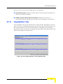
5.1.5 Capabilities Tab ................................................................................................ 53
5.1.6 Device Status for Multiple Device Configuration ............................................... 56
5.2 IP Parameters .............................................................................................................. 58
5.2.1 IP Settings ......................................................................................................... 59
5.2.2 DHCP Settings .................................................................................................. 60
5.2.3 Runtime IP Settings .......................................................................................... 60
5.3 Bridging Parameters ................................................................................................... 62
5.3.1 Bridging Parameters General Tab .................................................................... 62
5.3.2 Bridging Parameters VLAN Tab ........................................................................ 66
5.3.3 MAC Address Deny List Tab (AU only) ............................................................. 69
5.4 Air Interface Parameters............................................................................................. 74
5.4.1 Air Interface General Tab .................................................................................. 74
5.4.2 Air Interface Frequency Tab (Single Device) .................................................... 81
5.4.3 Air Interface Frequency Tab for Multiple Device Configuration ......................... 83
5.4.4 Air Interface DFS Tab (AU/BU only) ................................................................. 85
5.4.5 Air Interface Transmit Power Tab ..................................................................... 88
5.4.6 Air Interface Country Parameters Tab .............................................................. 91
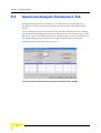
5.5 Spectrum Analysis Parameters Tab .......................................................................... 94
5.5.1 Scan Period ....................................................................................................... 96
5.5.2 Scan Cycles ...................................................................................................... 96
5.5.3 Automatic Channel Selection (AU/BU only) ...................................................... 96
5.5.4 Current Status ................................................................................................... 96
User Manual
ix
Contents
5.5.5 Reset Counters ................................................................................................. 96
5.5.6 Start Analysis .................................................................................................... 96
5.5.7 Refresh Interval (sec) ........................................................................................ 97
5.5.8 Start/Stop Automatic Refresh ............................................................................ 97
5.5.9 Spectrum Analysis Table .................................................................................. 97
5.6 Performance Parameters............................................................................................ 98
5.6.1 RTS Threshold (AU and SU only) ................................................................... 100
5.6.2 Minimum Contention Window (AU and SU only) ............................................ 100
5.6.3 Maximum Contention Window (AU and SU only) ........................................... 100
5.6.4 Number of Hardware Retries .......................................................................... 100
5.6.5 Average SNR Memory Factor ......................................................................... 101
5.6.6 Maximum Modulation Level ............................................................................ 101
5.6.7 Multicast Modulation Level (AU/BU only) ........................................................ 101
5.6.8 Burst Mode Option .......................................................................................... 101
5.6.9 Burst Interval ................................................................................................... 102
5.6.10 Concatenation Option ..................................................................................... 102
5.6.11 Adaptive Modulation Algorithm ....................................................................... 102
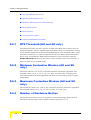
5.7 Service Parameters (AU, SU and RB)...................................................................... 103
5.7.1 User Filtering Parameters (SU/RB only) ......................................................... 104
5.7.2 MIR/CIR .......................................................................................................... 105
5.8 Security Parameters.................................................................................................. 107
5.8.1 Authentication Algorithm ................................................................................. 109
5.8.2 Data Encryption Option ................................................................................... 109
5.8.3 Security Mode ................................................................................................. 109
5.8.4 Promiscuous Authentication Option (AU/BU only) .......................................... 109
5.8.5 Default Multicast Key (AU/BU only) ................................................................ 109
x
BreezeACCESS VL and BreezeNET B Device Driver
Contents
5.8.6 Default Key (SU/RB only) ................................................................................ 109
5.8.7 Key 1 through Key 4 ........................................................................................ 109
5.9 Best AU/BU Parameters (SU/RB only)..................................................................... 110
5.9.1 Best AU/BU Support ....................................................................................... 111
5.9.2 Number of Scanning Attempts ........................................................................ 112
5.9.3 Preferred AU/BU MAC Address ...................................................................... 112
5.9.4 Clear Preferred AU MAC Address .................................................................. 112
5.9.5 Associated AU ................................................................................................. 112
5.9.6 Runtime ESSID ............................................................................................... 112
5.9.7 Neighboring AUs/BUs Table ........................................................................... 112
5.9.8 Selected AU/BU Details .................................................................................. 113
5.10Network Management Parameters .......................................................................... 114
5.10.1 Network Management General Parameters Tab ............................................ 114
5.10.2 Network Management Traps Tab .................................................................... 117
5.10.3 Network Management Telnet Tab ................................................................... 117
5.11Feature Upgrade ....................................................................................................... 119
5.11.1 Feature Upgrade - Single Device Configuration ............................................. 119
5.11.2 Feature Upgrade - Multiple Devices ................................................................ 120
5.12Performance Monitoring .......................................................................................... 121
5.13Traffic Counters ........................................................................................................ 124
5.13.1 Ethernet Counters ........................................................................................... 124
5.13.2 Reset Counters ............................................................................................... 125
5.13.3 Polling Interval ................................................................................................. 125
5.14Tx Counters............................................................................................................... 126
5.14.1 General Tx Counters ....................................................................................... 127
5.14.2 Submitted To Bridge ....................................................................................... 128
User Manual
xi
Contents
5.14.3 Wireless Tx Events ......................................................................................... 128
5.14.4 Retransmitted Frames ..................................................................................... 128
5.14.5 Dropped Frames ............................................................................................. 128
5.14.6 Discarded MIR/CIR ......................................................................................... 129
5.14.7 Concatenated Frames ..................................................................................... 129
5.14.8 Reset Counters ............................................................................................... 129
5.14.9 Polling Interval ................................................................................................. 129
5.15Rx Counters .............................................................................................................. 130
5.15.1 Wireless Rx Counters ..................................................................................... 130
5.15.2 Wireless Rx Events ......................................................................................... 131
5.15.3 Reset Counters ............................................................................................... 131
5.15.4 Polling Interval ................................................................................................. 131
5.16Per Modulation Level Counters (SU/RB) ................................................................ 132
5.16.1 Per Modulation Level Counters Table ............................................................. 132
5.16.2 Average Received SNR .................................................................................. 133
5.16.3 Average Modulation Level ............................................................................... 133
5.16.4 Reset Counters ............................................................................................... 133
5.16.5 Polling Interval ................................................................................................. 133
5.17Per SU Counters (AU)/BU Tx Statistics (BU).......................................................... 134
5.17.1 Per SU Counters/BU Tx Statistics Table ......................................................... 134
5.17.2 Reset Counters ............................................................................................... 135
5.17.3 Polling Interval ................................................................................................. 135
5.18Link Quality (SU/RB)................................................................................................. 136
xii
BreezeACCESS VL and BreezeNET B Device Driver
Contents
Chapter 6 - Performance Monitoring and BWA
PM Data Collection Counters
6.1 Performance Monitoring and BWA PM Data Collection Counters ....................... 138
6.1.1 Ethernet Statistics ........................................................................................... 139
6.1.2 Wireless Counters ........................................................................................... 139
6.1.3 Per SU Statistics (BWA PM Data Collection only) .......................................... 146
6.1.4 Per Mod Level Statistics (BWA PM Data Collection only) ............................... 151
6.1.5 Modulation Level Statistics (Performance Monitoring only) ............................ 155
6.1.6 Transmit Power Parameters (SU/RB only) ..................................................... 156
6.1.7 MIB II If Counters ............................................................................................ 156
User Manual
xiii
1
Chapter 1 - Discovery and Resync
Processes with BreezeACCESS VL and
BreezeNET B Devices
In This Chapter:
The functionality of the Discovery and Resync processes of AlvariSTAR depend on
the device family. This chapter describes the functionality of these processes with
BreezeACCESS devices.
“The Discovery Process” on page 1-2
“The Resync Process” on page 1-3
Chapter 1 - Discovery and Resync Processes with BreezeACCESS VL and BreezeNET B Devices
1.1
The Discovery Process
The discovery process can start only after one or more IP address ranges have
been defined. Each defined IP address range may be associated with a specific
pair of SNMP Read and Write communities. Alternatively, a list of global SNMP
Read and Write communities can be defined. These global pairs will be used with
all IP address ranges for whom a specific pair of Read and Write communities was
not defined. In addition, for each IP address range a location can be defined.
The discovery process is comprised of two phases. In the first phase, the system
accesses the defined addresses one by one, using Get SysOID SNMP requests with
the SNMP Read community defined for the applicable range. If no specific SNMP
community is defined, the system will try to access these addresses using the
defined global SNMP Read communities one after the other. If a device responded
to the Get SysOID request with a SysOID of a licensed device, the system will get a
few basic parameters from the device and will add it to the database using the
SysName. If the SysName is not defined, the device’s IP address will be used as its
name.
If the discovered device is not licensed (the number of discovered devices of its
type reached the maximum limit according to the license conditions), the Number
of Non Licensed Discovered Devices will be incremented by one and an alarm will
be generated. Devices with a non-licensed SysOID will be ignored.
In the second phase, the system gets some additional key parameters from the
discovered device, defines the device’s location and identifies wireless links to
other devices. The use of a different process for these tasks, that runs in parallel
to the actual discovery process, ensures that the discovery process will run at
maximum speed. The process activated in this phase is actually identical to the
Resync process.
Once the search parameters for the discovery process have been defined, it can be
configured to run periodically, accessing at each cycle, only devices that do not
exist in the database. For each of the defined IP address ranges, the cyclic
discovery process can be enabled/disabled separately. A discovery cycle may also
be initiated and/or terminated manually.
NOTE
Discovery/Resync parameters cannot be configured while the discovery process is running.
2
BreezeACCESS VL and BreezeNET B Device Driver
The Resync Process
1.2
The Resync Process
The Resync process can only start once there is at least one discovered device in
the database. The Resync application is responsible for accessing devices that
exist in the database, obtaining key parameters from each device and updating
the database accordingly. Upon identifying certain changes, special actions may
be taken, such as updating the database, initiating rediscovery or generating an
alarm. The Resync process is also responsible for identifying wireless links
between devices. This includes links to non-discovered devices, such as devices
that are not included in the defined IP address ranges, devices that have not been
discovered yet and devices that did not respond (currently not active).
The resync process can be configured to run periodically, accessing at each cycle
the devices that exist in the database.
NOTE
It is recommended to schedule the Resync process to run at non-busy hours. Intervals between
resync clycles should be in accordance with expected rate of changes in the system. Typically the
resync process should run every two weeks.
For each of the IP address ranges, the resync process can be enabled/disabled
separately. A Resync cycle may also be initiated and/or terminated manually.
NOTE
Discovery/Resync parameters cannot be configured while the Resync process is running.
A Resync process is also automatically activated as the second phase of the
discovery process following discovery of new devices. This “post-discovery” process
is independent of the regular cyclic or manually initiated process.
Each discovered device is associated with a location. A location can be defined for
each IP address range using the Location Manager. This location will be the
parent location for the discovered devices in this range. Otherwise, the IP address
range will be used as the default parent location. For an AU or a BU, a new
location is created under this parent location. The default name of the AU’s/BU’s
location is its System Name, or its IP address if a System Name does not exist. For
Non-Discovered AUs/BUs a new location is not generated, and they are moved to
the parent location as described above.
It is also possible to use location definition functionality based on the CPE Follow
Base algorithm. When this feature is enabled, all the SUs associated with the AU,
User Manual
3
Chapter 1 - Discovery and Resync Processes with BreezeACCESS VL and BreezeNET B Devices
or the RB associated with the BU, are also moved to the location of the AU/BU,
including Non-Discovered SUs/RBs. If the CPE Follow Base feature is not
enabled, the SUs/RBs will be moved to the parent location.
In addition to the scheduled Resync described above, the system may initiate
non-scheduled (background) resync processes. A background resync process is
initiated whenever the system identifies an event that necessitates a database
update process for certain devices. Such events include completion of a SW
upgrade session and discovery of a new device (post-discovery Resync). Unlike the
scheduled resync that is being executed for one device at a time, several
background resync processes may run in parallel. A background resync process is
controlled by the system, and the users cannot stop or start it.
4
BreezeACCESS VL and BreezeNET B Device Driver
2
Chapter 2 - Using the Equipment Manager
with BreezeACCESS VL and BreezeNET B
Devices
In This Chapter:
The functionality of the Equipment Manager with BreezeACCESS devices is
affected by the system’s architecture. This affects the device types, which are
displayed in the Returned Equipment list and in the Selected Items list, and the
method of selecting equipment for various sessions.
Chapter 2 - Using the Equipment Manager with BreezeACCESS VL and BreezeNET B Devices
2.1
Using the Equipment Manager
The Returned Equipment list includes all devices that meet the selected Criteria
Scheme parameters. This includes the following device types:
BreezeACCESS_VL_AU (Access Unit)
BreezeACCESS_VL_SU (Subscriber Unit)
BreezeNetB_BU (Base Unit
BreezeNetB_RB (Remote Bridge)
The background color of the icon on the left side of each device indicates the
alarm status of the device.
To move devices to the Selected Items List:
Select one or more items (use the Shift and Ctrl keys to select multiple devices) in
the Returned Equipment list to move them to the Selected Items list.
To select BreezeACCESS devices either in the Equipment Manager window or
when accessing the Select Equipment window from another window:
1
Define the required Criteria Scheme and click on Go.
2
From the Returned Equipment list, select the required devices. The selected
items are displayed in the Selected items list.
3
To select multiple devices for the session, use the Shift and Ctrl keys. The
selected devices will be added to the session.
6
BreezeACCESS VL and BreezeNET B Device Driver
3
Chapter 3 - Using the Software Upgrade
Session Editor with BreezeACCESS VL and
BreezeNET B Devices
In This Chapter:
“Adding and Editing Software Upgrade Sessions” on page 3-8
“The General Tab” on page 3-10
“The Devices Tab” on page 3-13
“The Scheduler Tab” on page 3-15
“The TFTP Settings Tab” on page 3-16
“The Operations Tab” on page 3-17
Chapter 3 - Using the Software Upgrade Session Editor with BreezeACCESS VL and BreezeNET B Devices
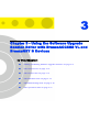
3.1
Adding and Editing Software Upgrade
Sessions
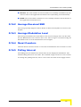
The New/Edit Software Upgrade Session window lets you define new software
upgrade sessions and edit existing sessions.
To create/edit a software upgrade session:
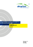
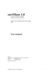
From the Software Upgrade Manager window, click New to create a new session,
or Edit to modify the current session. The following window is displayed:
Figure 3-1: New/Edit Software Upgrade Session Window
The New/Edit Software Upgrade Session window includes the following tabs:
General (see “The General Tab” on page 3-10) - for defining general session
parameters and software files to be loaded, viewing details on sessions status
and managing selected sessions.
Devices (see “The Devices Tab” on page 3-13) - for adding or removing devices
to be upgraded in the applicable session and viewing relevant details related to
these devices.
Scheduler (see “The Scheduler Tab” on page 3-15) - for defining session’s start
date and time and optionally the maximum length of each session.
8
BreezeACCESS VL and BreezeNET B Device Driver
Adding and Editing Software Upgrade Sessions
TFTP Settings (see “The TFTP Settings Tab” on page 3-16) - for defining TFTP
parameters for the session.
Operations (see “The Operations Tab” on page 3-17) - for defining software
versions management of the upgraded devices.
User Manual
9
Chapter 3 - Using the Software Upgrade Session Editor with BreezeACCESS VL and BreezeNET B Devices
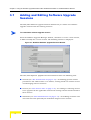
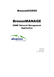
3.2
The General Tab
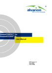
The General tab of the New/Edit Software Upgrade Session window lets you define
general session parameters, view details on the progress of existing sessions and
manage selected sessions.
Figure 3-2: New/Edit Software Upgrade Session - General Tab
The fields displayed in the General tab are described below:
Field
Description
Session
Enter the name for the new session. This is a
Name
read-only field when editing an existing session. The
session name can include up to 20 characters and
must be unique in the server database.
Session
Enter a description for the new session or edit the
Description
description of an existing session. The session
description can include up to 60 characters.
Session
Read-only field that displays the status of the
Status
session: New, Aborted, Failed, Finished, Paused,
Running or Scheduled.
10
Cycle
Read-only field that displays the progress in % of the
Progress
current session’s cycle.
Total Number
Read-only field that displays the total number of
Of Devices
devices participating in the upgrade session.
BreezeACCESS VL and BreezeNET B Device Driver
The General Tab
Field
Description
Number Of
Read-only field that displays the number of devices
Succeeded
for which the upgrade operation has been completed
Devices
successfully.
Number Of
Read-only field that displays the number of devices
Failed
for which the upgrade operation has failed.
Devices
Number Of
Read-only field that displays the number of devices
Uploading
which are currently being uploaded.
Devices
Policy In case
Select from the drop-down list, the policy to be
Of Failure
adopted when a failure occurs (Stop Session or
Continue Session). The Stop/Continue Session refers
to the next step (if any) according to the software
versions control process as defined in the Operations
tab.
If the Continue Session option is selected, the second
step (if defined) will be carried on only for devices for
which the first step was completed successfully .
If the Stop Session is selected, the application will
carry out the next step in the process only if the
current step operations are successful on all the
devices in the session.
User Manual
Version Root
Read-only field that displays the path to the software
Path
files in the Application Server.
Software
From the drop-down list, select the software version
Version
to be loaded.
11
Chapter 3 - Using the Software Upgrade Session Editor with BreezeACCESS VL and BreezeNET B Devices
Field
Description
Upgrade
From the drop-down list select the policy for loading
Mode
software versions that already exist in the target
device:
Always - Upload without checking the software
versions in the target device.
Different From Current Version - Upload only if the
loaded version differs from the current version in
the target device.
Different From Shadow Version - Upload only if the
loaded version differs from the shadow version in
the target device.
Different From Current and Shadow Version Upload only if the loaded version differs from both
the current and the shadow versions in the target
device.
The selected option should take into account the
software versions management policy in the target
devices.
Use the buttons on the right side of the window for managing sessions:
NOTE
Failed devices for the Retry option are defined as devices for whom at least one requested
operation failed (either upload or a software version control operation). See Operations tab for more
details.
12
Button
Description
View Log
Click to open the Log Report manager.
BreezeACCESS VL and BreezeNET B Device Driver
The Devices Tab
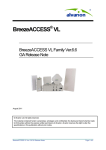
3.3
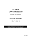
The Devices Tab
The Device tab of the New/Edit Software Upgrade Session window lets you view
relevant details related to devices participating in an existing session, add or
remove devices to the list of devices participating in the session and create a list of
devices for a new session.
Figure 3-3: New/Edit Software Upgrade - Devices Tab
The read-only devices table displays the following details for each of the devices
defined in the session:
Field
Description
Name
The device’s name.
Type
The device’s type.
Location
The device’s location.
Running Ver
The devices’s current running software version
Software Ver
The device’s current main software version.
Shadow Ver
The device’s shadow software version.
HW Version
The device’s hardware version.
Use the buttons on the right side of the window for adding or removing devices
to/from the list:
User Manual
13
Chapter 3 - Using the Software Upgrade Session Editor with BreezeACCESS VL and BreezeNET B Devices
Button
Description
Add
Click to open the Select Equipment window for adding devices
to the list.
Remove
Select one or several devices from the table and click Remove
to delete the selected device(s) from the session.
14
BreezeACCESS VL and BreezeNET B Device Driver
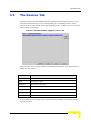
The Scheduler Tab
3.4
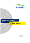
The Scheduler Tab
The Scheduler tab of the New/Edit Software Upgrade Session window lets you
define the start date and time for the session. It optionally enables limiting the
length of the session. A session that was not completed because the maximum
length of time defined for it has been reached, will be rescheduled automatically
for the same start time on the next day.
Figure 3-4: New/Edit Software Upgrade Session - Scheduler Tab
The fields displayed in the Scheduler tab are described below:
Field
Description
Start Date
Enter the required start date or click on the Browse button to
and Time
open the Select a Date Calendar window. Enter the start time
using a 12-hours clock format (or use the up/down arrows)
and select am or pm from the drop-down list.
Stop After
Check to enable defining the maximum length of the session.
When checked, you can select Hour/s or Minute/s from the
drop-down list and enter the session length (or use the
up/down arrows). Available values for maximum session
length are 1 to 9999 (Hours or Minutes).
User Manual
15
Chapter 3 - Using the Software Upgrade Session Editor with BreezeACCESS VL and BreezeNET B Devices
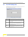
3.5
The TFTP Settings Tab
The TFTP Settings tab of the New/Edit Software Upgrade Session window lets you
define TFTP parameters for the session.
Figure 3-5: New/Edit Software Upgrade Session - TFTP Settings Tab
The fields displayed in the TFTP Settings tab are described below:
Field
Description
Timeout
Defines the time, in seconds, that the TFTP process waits for
an acknowledgement message for each packet. The range is 1
to 120 seconds.
Retries
Defines the maximum number of retries, which is the
number of times a packet is retransmitted when an
acknowledgement is not received within the defined timeout
period. The range is 0 to 10.
Attempts
Defines the number of times the TFTP session is retried
before determining that the upgrade procedure has failed.
The range is 0 to 10.
16
BreezeACCESS VL and BreezeNET B Device Driver
The Operations Tab
3.6
The Operations Tab
In BreezeACCESS VL and BreezeNET B systems, the SU/RB units are upgraded
first, followed by the AU/BU units. If an AU-SU or BU-RB pair is defined as a
Repeater (SU/RB connected back-to-back with an AU/BU), then all SU/RB units
served by the repeater are upgraded first, followed by the repeater AU/BU units.
Finally, the repeater’s SU/RB and the AU/BU that serves the repeater’s SU/RB
are upgraded.
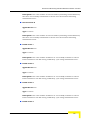
The Operations Tab of the New/Edit Software Upgrade Session window enables
the management of software versions in the devices participating in the session.
Software versions management can be defined as steps in the upgrade process
(what to do once a new software version has been successfully loaded), or as an
independent session that does not include the actual loading process (separating
the software loading process from the software versions control process).
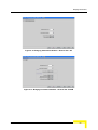
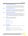
Figure 3-6: New/Edit Software Upgrade Session - Operations Tab
User Manual
17
Chapter 3 - Using the Software Upgrade Session Editor with BreezeACCESS VL and BreezeNET B Devices
The Operations tab is comprised of the following fields:
Field
Description
Upload
Check to upload a new software version to devices, according
to the policy defined by Upgrade Mode in the General tab.
If the Upload option is checked, the options for Devices
running from shadow become available. Since a new version
cannot be loaded to a device that is running from the shadow
version, the required option must be selected:
Ignore: The device will not participate in the session.
Reset to main ver: Before loading a new software version,
a reset operation is performed in order to get the device to
run from the main software version.
Change main ver: Before loading a new software version,
a Change Version After Reset To Current operation is
performed. The software version that the device is running
becomes the main version. No reset is performed.
Reset and
Check to reset the device and reboot it from its shadow
Run From
version. If Upload is checked, this will be performed only
Shadow
after the new software version has been successfully loaded.
Change
Check to use the running version as the main version after
Version After
reset.
Reset To
Current
If two or more of these optional steps are selected, then the system completes the
first step for all devices participating in the session before proceeding to the next
step. If a step was not completed successfully for one or more devices, the system
executes the next step(s) only if the Continue Session option has been selected in
the Policy In Case Of Failure field in the General tab.
18
BreezeACCESS VL and BreezeNET B Device Driver
The Operations Tab
The Devices Status Table includes the following details for each of the devices
participating in the session:
Field
Description
Name
The device’s name.
Upload
The status of the Upload process (if Upload option is
Status
checked).
Run from
The status of the Run From Shadow status (if the Reset And
Shadow
Run From shadow option is checked).
Status
Change to
The status of the Change to Current Version process (if the
Current
Change Version after Reset To Current option is checked).
Status
The possible options for the Status entries are:
Succeed: Operation was completed successfully
Failed: Operation failed
Ignored: Operation was requested but not executed. For
upload operation-if the upload to the device was skipped
because of selected Upgrade Mode rules. For software
version control operations - if the previous step failed.
Repeater
Indicates if the device is defined in the database as a part of a
repeater. This functionality determines the order of the
upgrade and multiple configuration processes for different
equipment types has no effect on the database.
User Manual
19
4
Chapter 4 - Using The Device Manager
In This Chapter:
The Device Manager enables you to manage, monitor and configure BreezeACCESS
VL and/or BreezeNET B devices.
The Device Manager has two modes of operation:
Single Device Manager - for managing, monitoring and configuring one
selected device.
Multiple Devices Manager - for simultaneously managing and configuring
multiple devices.
This chapter describes how to access the Device Manager and provides a brief
description of each workspace component.
This chapter is comprised of the following sections:
“Introducing the Single Device Manager” on page 4-22
“Introducing the Multiple Devices Manager” on page 4-24
“Using the Device Manager Workspace” on page 4-28
“Menu Options” on page 4-34
Chapter 4 - Using The Device Manager
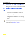
4.1
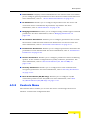
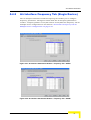
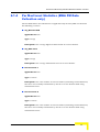
Introducing the Single Device Manager
The Device Manager enables you to manage a selected device using a wide array of
controlling, monitoring and configuration options.
4.1.1
Accessing the Single Device Manager
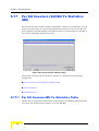
To access the Single Device Manager:
1
From the File>Open>AlvariSTAR menu, or from the Navigation Pane, select
Inventory, and then Equipment Manager. Select the appropriate filtering
criteria and click GO.
The Equipment Manager displays a list of all the equipment in the database
that match the selected criteria.
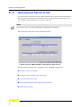
2
From the list of found devices, select the device you want to configure, and
click the Open button on the right side of the window - The Device Manager is
opened, and the Device Status window (Properties tab) is displayed in the
workspace.
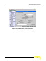
NOTE
The title bar of the AlvariSTAR window displays information about the managed device: Type (AU,
SU, BU or RB), Model (e.g. SU-6-BD, AU-BS, RB-B28), Name and IP Address.
To configure devices, see “Managing Devices” on page 5-41.
22
BreezeACCESS VL and BreezeNET B Device Driver
Introducing the Single Device Manager
Figure 4-1: Device Status Window (for the selected device)
User Manual
23
Chapter 4 - Using The Device Manager
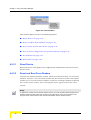
4.2
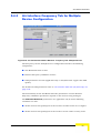
Introducing the Multiple Devices
Manager
4.2.1
Overview
The Multiple Devices Manager enables you to download configuration parameters
to multiple units simultaneously, including different unit types, such as
Subscriber Units, Access units, Base Units and Remote bridges. The options are
described in the following Chapter.
When this option is selected in the Equipment Manager (after selecting the
required devices), the system verifies that all selected devices belong to the
BreezeACCESS VL and/or BreezeNET B family. If the list of selected devices
includes devices that are not discovered yet (the system identified their existence
but actual discovery was not performed yet), a message notifying that these
devices do not participate in the Multiple Configuration is displayed. The list of
devices that will eventually participate in the multiple configuration process can
be further refined by editing the Device List in the Multiple Configuration window.
The available windows include all the configuration windows that are available for
any one or some of the relevant devices (AU, SU, BU and RB) in the single unit
Device Editor. Each window includes all parameters that are configurable (write)
for at least one device type. The Multiple Configuration loading mechanism loads
each unit only with the parameters that are applicable to the unit, taking into
account the Unit Type and its Software Version. To ensure a smooth process while
minimizing the risk of losing connectivity to devices, the SUs/RBs are modified
before the AUs/BUs. If an AU-SU or a BU-RB pair is defined as a Repeater
(SU/RB connected back to back with an AU/BU), then the all the SUs or the RB
served by the repeater are upgraded first, followed by the AU/BU of the repeater,
and then the SU/RB of the repeater. Finally, the AU/BU that serves the repeater’s
SU/RB is upgraded.
If the loading process to one or more devices failed, a notification message is
displayed, and the failed devices in the Device List are marked in red. The log
report includes the reason of the failure:
Error – The unit rejected the parameters set.
Time Out – The unit did not respond timely.
24
BreezeACCESS VL and BreezeNET B Device Driver
Introducing the Multiple Devices Manager
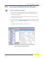
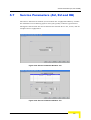
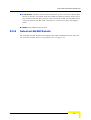
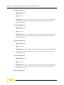
4.2.2
Accessing the Multiple Devices Manager
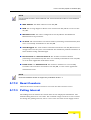
To access the Multiple Devices Manager
1
From the File>Open>AlvariSTAR menu, or from the Navigation Pane, select
Inventory, and then Equipment Manager. Select the appropriate filtering
criteria and then click GO.
The Equipment Manager displays a list of all the equipment in the database
that match the selected criteria.
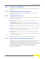
2
From the list of found devices, select the two or more devices that you want to
configure, and click the Multiple Configuration button on the right side of the
window.
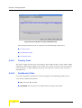
The Multiple Configuration Window is shown below.
Figure 4-2: Multiple Configuration Window
User Manual
25
Chapter 4 - Using The Device Manager
4.3
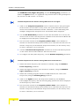
The Device Manager Workspace
Components
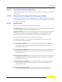
In this section, the Device Manager workspace components are listed, and shown
in the following example window.
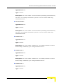
Figure 4-3: The Device Manager Workspace Components
The Device Manager workspace is comprised of the following components:
Menu Bar:
Enables you to access multiple options and application
functionality. For more information, see “Menu Options”
on page 4-34
Selected Window:
The Selected window depends on the option selected on
the Menu Bar. It displays, for the applicable parameters,
the correct configuration loaded from the device, and
enables the setting of new values for configuration
parameters.
Control Buttons:
All windows contain the same Control Buttons. For
more information see “Control Buttons” on page 4-29.
26
BreezeACCESS VL and BreezeNET B Device Driver
The Device Manager Workspace Components
Secondary Tabs:
Certain windows are divided into multiple workspaces,
to provide all required parameters in the selected
category. In these cases, the window contains a
Secondary Tabs area.
Device List:
In the Multiple Configuration window, the Device List
area enables you to edit the list of devices that will
participate in the multiple configuration process. For
more information, see “The Device List (Multiple
Configuration)” on page 4-30.
User Manual
27
Chapter 4 - Using The Device Manager
4.4
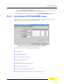
Using the Device Manager Workspace
This section describes how to use the Device Manager Workspace. This includes
the Control Buttons common to all windows and the Window Navigation Buttons
(opened from the Window menu) and all other Menus. In addition, common table
sort, workspace resize, Device List and parameter selection functions are
described. The Driver Manager Workspace window is displayed below.
Figure 4-4: The Device Editor Workspace Window
This section includes:
“Control Buttons” on page 4-29
“The Device List (Multiple Configuration)” on page 4-30
“Navigating the Windows in the Current Session” on page 4-31
“Resizing the Workspace” on page 4-32
“Manipulating Tables” on page 4-32
28
BreezeACCESS VL and BreezeNET B Device Driver
Using the Device Manager Workspace
“Selecting Parameter Values” on page 4-33
“Tool-tips” on page 4-33
“Grayed-out Fields” on page 4-33
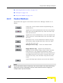
4.4.1
Control Buttons
The buttons that appear at the bottom of the Device Manager window are as
follows:
Closes the current window without implementing any
modifications.
Applies the current modifications and closes the window.
Note that some modifications may come into effect only
after the next reset
Applies the current modifications, closes the window and
resets the device. All modifications come into effect after
the reset.
Implements the current modifications without closing
the window. Some modifications may come into effect
only after the next reset.
Multiple Devices only: - Clears the window fields.
Single Devices only: - Updates the information
displayed in the window using current values acquired
from the device. The displayed information reflects
recently made modifications, which for some parameters
may differ from the actual values currently used by the
unit (because they come into effect only after the next
reset).
Opens the Help Topic window for the selected window.
NOTE
The Control Buttons function exclusively in the current window. This means that clicking
Apply saves only the configuration from the current window and does not apply the
changes made in previous windows.
User Manual
29
Chapter 4 - Using The Device Manager
4.4.2
The Device List (Multiple Configuration)
The left side of the Multiple Configuration window includes the device list. The
window opens with all the already discovered devices selected in the Equipment
Manager.
This section includes:
“Editing the Device List” on page 4-30
“The Remove Succeeded Devices Button” on page 4-30
4.4.2.1
Editing the Device List
You can edit the Device List by selecting one or more devices and using the mouse
right-click to remove the devices that are not required for multiple configuration
operation.
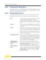
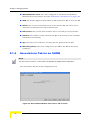
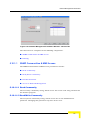
4.4.2.2
The Remove Succeeded Devices Button
Following a multiple configuration process where one or more devices failed, the
failed devices are marked in red, and the Remove Succeeded Devices button at the
bottom of the window becomes active.
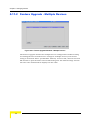
Click the Remove Succeeded Devices button to remove all succeeded devices
from the list (the failed devices remain listed). To retry loading the updated
configuration to the failed devices, press Apply or OK.
30
BreezeACCESS VL and BreezeNET B Device Driver
Using the Device Manager Workspace
Figure 4-5: Multiple Configuration - Removing Successfully Configured Devices
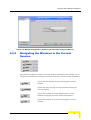
4.4.3
Navigating the Windows in the Current
Session
The window navigation buttons accessed from the Windows menu enable you to
navigate the windows previously accessed during the current session, as follows:
Opens the first window accessed during the current
session.
Opens the most recently accessed window during the
current session.
Opens the window accessed following the current
window during the previous chain of navigation
Opens the window accessed last during the current
session.
User Manual
31
Chapter 4 - Using The Device Manager
4.4.4
Resizing the Workspace
AlvariSTAR enables you to resize the workspace, as required. Hold the cursor over
the edge of the workspace until it is displayed as a double-headed arrow. Click
and drag to resize the window, as needed.
4.4.5
Manipulating Tables
AlvariSTAR enables you to sort, reorder and resize all tables displayed in the
workspace. For many tables, it also enables you to delete multiple entries.
Sort:
To sort a table by any of the table headings, click the
required table heading. The table is sorted
alphabetically in ascending order, according to the
selected parameter. Click again to sort in descending
order.
Reorder:
To reorder the columns displayed in any table, click
and drag the required column to the required location
in the table.
Resize:
To resize the columns displayed in any table, hold the
cursor over the edge of the column heading until it is
displayed as a double-headed arrow. Click and drag to
resize the column, as needed. All other columns are
resized automatically. The overall width of the table,
however, does not change.
Entering new values:
To enter a new value, click in the required row. The
current value must be deleted prior to entering a new
value. Alternatively, you may either double-click the
current value or drag the cursor across the existing
value to highlight it. Enter the required value. The
previous value is automatically deleted.
Deleting Entries
To delete one or more entries, mark the selected
(Multiple Devices
entries and then right-click the mouse. Click on the
only)
Delete Selected Entries pop-up menu to delete the
entries. The deleted entries are marked in red.
Clearing Selected
To clear unwanted displayed entries before applying
Rows
changes to required entries, mark the selected entries,
and then right-click the mouse. Click on the Clear
Selected Rows pop-up menu to clear the selected
fields in the display.
32
BreezeACCESS VL and BreezeNET B Device Driver
Using the Device Manager Workspace
4.4.6
Selecting Parameter Values
The following methods for selecting the required value for parameters within the
application are common to most configuration windows:
Dropdown Menus:
Parameters with several value options are configured
using dropdown menus that include the available
options. To configure these parameters, select the
required option from the dropdown menu. The value is
displayed in the field.
Up/Down
Parameters with value ranges are configured using up
Selection Arrows:
and down arrows to navigate through the range of values
available. Click the up and down arrows until the
required option is displayed in the field. You can also
enter the required value directly into the field.
4.4.7
Tool-tips
Tool-tips are common to all configuration windows in the Device Manager. These
are displayed whenever you move the mouse over buttons and tabs. Apart from
displaying the functionality of the object, tooltips also display parameter ranges in
up/down combo boxes.
4.4.8
Grayed-out Fields
Grayed-out fields are read-only. This may be due to the particular parameter
being read-only, or because another parameter must be changed to enable
read-write access for the required parameter.
User Manual
33
Chapter 4 - Using The Device Manager
4.5
Menu Options
This section describes all the menus and options available in the Main Menu of
the configuration windows:
“Configuration Menu” on page 4-34
“Controls Menu” on page 4-35
“Site Survey Menu (Single Device)” on page 4-38
“Settings Menu” on page 4-39
“Window Menu” on page 4-39
“View Logs” on page 4-39
“Help Menu” on page 4-39
“Close” on page 4-39
4.5.1
Configuration Menu
The Device Configuration menu enables you to access the main configuration
parameters for the selected device. The selectable items in the Configuration menu
may vary to reflect the parameter groups that are applicable for the selected
device.
The Multiple Devices Configuration menu enables you to access the main
configuration parameters for the selected device. The available configuration
windows include all the configuration windows that are available in the Single
Device Configuration for any of the relevant device types. Each window displays
all parameters that are configurable (write) for at least one device type;
informational parameters that are read-only for all device types are not displayed.
All relevant fields become write-only.
In multiple device configuration, the application does not perform any read
operation.
The Configuration menu includes the following options:
34
BreezeACCESS VL and BreezeNET B Device Driver
Menu Options
Device Status: Displays status information for the selected unit and enables
you to configure general parameters such as the device name and location. For
more information, refer to “Device Status Parameters” on page 5-43.
IP Parameters: Enables you to configure IP parameters for the device and
control the device's method for IP parameter acquisition. For more
information, refer to “IP Parameters” on page 5-58.
Bridging Parameters: Enables you to configure bridge, VLAN support and ToS
parameters. For more information, refer to “Bridging Parameters” on
page 5-62.
Air Interface Parameters: Enables you to configure parameters that control
the wireless communication between the Subscriber and Access Units. For
more information, refer to “Air Interface Parameters” on page 5-74.
Performance Parameters: Enables you to configure parameters that affect the
performance of the wireless link. For more information, refer to “Performance
Parameters” on page 5-98.
Service Parameters: Enables you to configure parameters related to filtering
options. It also enables configuration of Quality of Service parameters. For
more information, refer to “Service Parameters (AU, SU and RB)” on
page 5-103.
Security Parameters: Enables you to configure data and authentication
encryption parameters. For more information, refer to “Security Parameters”
on page 5-107.
Best AU Parameters (SU/RB only): Enables you to configure AU/BU
association preferences for SUs/RBs. For more information, refer “Best
AU/BU Parameters (SU/RB only)” on page 5-110.
4.5.2
Controls Menu
The Controls menu enables you to reset the device and manage the device’s
software versions and configuration files.
User Manual
35
Chapter 4 - Using The Device Manager
Figure 4-6: Controls Menu
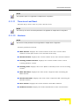
The Controls Menu includes the following options:
“Reset Device” on page 4-36
“Reset and Boot From Shadow” on page 4-36
“Use Current Version After Reset” on page 4-37
“Save Current Configuration As Operator Default” on page 4-37
“Set Defaults” on page 4-37
“Exit Telnet” on page 4-38
4.5.2.1
Reset Device
Resets the device and applies any configuration modifications introduced since
the last reset.
4.5.2.2
Reset and Boot From Shadow
Activates the shadow software version. The device’s flash memory can store two
software versions – one active and another inactive shadow version. This option
enables you to test the inactive software version by running it without replacing
the current active version, since resetting the device again restores the active
version.
NOTE
To replace the current version with the shadow version, you must first select Reset and Boot from
Shadow Version and then select Use Current Version After Reset. If not, the unit reverts to the
original current version after the next reset and the shadow version remains inactive.
36
BreezeACCESS VL and BreezeNET B Device Driver
Menu Options
4.5.2.3
Use Current Version After Reset
Defines the currently running version as the version to be activated and used after
the next reset.
4.5.2.4
Save Current Configuration As Operator Default
Enables you to save the current configuration as a configuration file to be used as
the Operator defaults. To activate the Operator defaults configuration, refer to Set
Operator Defaults below.
4.5.2.5
Set Defaults
There are two sets of default parameters, as follows:
Factory Defaults: Revert the system parameters to the original factory defaults
(see Full Factory and Partial Factory Defaults below).
Operator Defaults: Revert the system parameters to the configuration defined as
the Operator's defaults. The Operator can define a configuration file as the
Operator's default (see Full Operator and Partial Operator Defaults below).
The actual operation will be executed after the next reset.
Set Defaults enables you to reset the system parameters to the factory and
operator default values as follows:
Full Factory Defaults: Reverts all parameters, except for the AU Frequency
and the Passwords, to the factory default values. Note that you may lose
connectivity to the unit.
Partial Factory Defaults: Reverts all parameters to the factory default values
except for those parameters that are necessary to ensure connectivity and
management access.
Full Operator Defaults: Reverts all parameters, except for the AU Frequency
and the Passwords, to the Operator default values. Note that you may lose
connectivity to the unit.
Partial Operator Defaults: Reverts all parameters to the Operator default
values except for the parameters necessary to ensure connectivity and
management access.
Cancel Pending Operation: Select this option to cancel a pending Set
Defaults request (Set Defaults operation is executed only after reset).
User Manual
37
Chapter 4 - Using The Device Manager
4.5.2.6
Exit Telnet
The Exit Telnet option is applicable to Single Device Configuration only. It
enables you to terminate a current Telnet session to the unit.
4.5.3
Site Survey Menu (Single Device)
NOTE
The Site Survey Menu is available only in Single Device configuration.
The Site Survey menu enables you to view traffic and performance statistics for
the selected device.
The Site Survey menu is used to display the results of various tests and counters
for verifying the quality of the wireless link. This information can be used to help
determine where to position the units for optimal coverage, antenna alignment
and to assist in troubleshooting.
The Site Survey menu includes the following options:
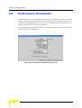
Performance Monitoring: Enables viewing the real-time graphs of the rates
(frames/second) of selected counters. For more details refer to “Performance
Monitoring” on page 5-121
Traffic Counters: Displays general Ethernet traffic statistics for the selected
unit. For more information, refer to “Traffic Counters” on page 5-124.
Tx Counters: Displays statistics regarding the traffic transmitted from the
selected unit. For more information, refer to “Tx Counters” on page 5-126.
Rx Counters: Displays statistics regarding the traffic received by the selected
unit. For more information, refer to “Rx Counters” on page 5-130.
Per Modulation Level Counters (SU/RB only): Displays information on
traffic transmitted by the SU/RB for each of the applicable modulation levels.
Refer to “Per Modulation Level Counters (SU/RB)” on page 5-132.
Per SU Counters (AU)/BU Tx Statistics (BU): For each of the associated SUs,
or the RB, displays information on the traffic transmitted to the SU/RB at
each of the applicable modulation levels. Refer to “Per SU Counters (AU)/BU
Tx Statistics (BU)” on page 5-134.
38
BreezeACCESS VL and BreezeNET B Device Driver
Menu Options
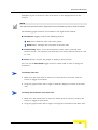
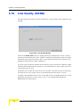
Link Quality (SU/RB only): Enables to view the quality of the uplink to the
AU/BU using the Average Modulation Level of transmitted frames as the link
quality indicator. For more details refer to “Link Quality (SU/RB)” on
page 5-136.
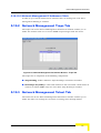
4.5.4
Settings Menu
The Setting menu enables access to Network Management parameters and to the
Feature Upgrade window.
Network Management Parameters: Enables you to configure filtering
parameters to limit access to the unit for management purposes and
parameters related to traps. It also enables you to define the Telnet time-out.
For more information, refer to “Network Management Parameters” on
page 5-114.
Feature Upgrade: The Feature Upgrade window enables you to upload
Feature License or Country Code strings to one or several devices. For more
information, refer to “Feature Upgrade” on page 5-119.
4.5.5
Window Menu
Enables you to browse the windows previously accessed. For more information,
refer to “Navigating the Windows in the Current Session” on page 4-31.
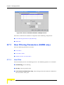
4.5.6
View Logs
NOTE
View Logs is enabled for Multiple Device Configuration only.
Select to open the AlvariSTAR Log for the Multiple Configuration Process.
4.5.7
Help Menu
Selecting Device Configuration Help from the Help Menu opens the Help Navigator
and Help Topic window for the current Device Driver.
4.5.8
Close
Closes the Device Manager for the current device.
User Manual
39
5
Chapter 5 - Managing Devices
In This Chapter:
Many management options provided by the Device Manager depend on the type of
device being configured.
When managing a single unit, the parameters and options displayed in the Device
Manager Window depend on the selected unit type.
In multiple devices configuration, the workspace includes parameters relevant to
any of the relevant device types (AU, SU, BU or RB). In addition, only configurable
parameters are available in multiple devices configuration.
NOTE
This Section presents the windows as they appear when configuring a single AU or SU device.
Some of the parameters may not be applicable to BU or RB devices. These parameters are marked
accordingly in the text. If you are working in multiple devices configuration, refer to the window
according to the type of device.
For detailed information on each of the parameters refer to the relevant System
Manual.
Managing Devices includes the following options:
Configuration Menu Options
“Device Status Parameters” on page 5-43
“IP Parameters” on page 5-58
“Bridging Parameters” on page 5-62
“Air Interface Parameters” on page 5-74
Chapter 5 - Managing Devices
“Performance Parameters” on page 5-98
“Service Parameters (AU, SU and RB)” on page 5-103
“Security Parameters” on page 5-107
“Best AU/BU Parameters (SU/RB only)” on page 5-110
Settings Menu Options
“Network Management Parameters” on page 5-114
“Feature Upgrade” on page 5-119
Site Survey Options (Single Configuration Only)
“Performance Monitoring” on page 5-121
“Traffic Counters” on page 5-124
“Tx Counters” on page 5-126
“Rx Counters” on page 5-130
“Per Modulation Level Counters (SU/RB)” on page 5-132
“Per SU Counters (AU)/BU Tx Statistics (BU)” on page 5-134
“Link Quality (SU/RB)” on page 5-136
42
BreezeACCESS VL and BreezeNET B Device Driver
Device Status Parameters
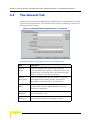
5.1
Device Status Parameters
The Device Status window enables you to define general device parameters such
as the name and location of the selected unit. In addition, the Device Status
window displays details regarding the unit's firmware and hardware versions. For
an SU/RB, information regarding its associated AU/BU is displayed, and for an
AU/BU, information regarding its associated SUs/RB is displayed.
Single (Device) Configuration: The Device Status window is divided into three
tabs:
The Properties tab includes the device’s Status parameters.
The Associations Tab in the AU/BU includes additional details about the
associated SUs/RB. In an SU/RB, the Associations Tab includes information
about the associated AU/BU.
The Capabilities tabs provide information on HW and SW capabilities of
relevant units. In an AU/BU, the information provided in the tab is for all
associated SUs or RB. In an SU/RB, the tab includes information on all
AUs/RBs in the neighboring AUs/BUs table (all AUs/BUs with whom the
SU/RB can communicate).
Multiple (Device) Configuration: In multiple device configurations, a single
Device Status tab includes only a small subset of the parameters available in
single device configuration.
The Device Status window is accessed from the Configuration Menu.
This section includes:
“Device Status Properties Tab” on page 5-44
“Associations Tab for an AU” on page 5-48
“Associations Tab for an SU/RB” on page 5-52
“Capabilities Tab” on page 5-53
“Device Status for Multiple Device Configuration” on page 5-56
User Manual
43
Chapter 5 - Managing Devices
5.1.1
Device Status Properties Tab
The Device Status Properties Tab is displayed below.
Figure 5-1: Device Status Properties Tab
The Device Status Properties tab is comprised of the following components:
Unit Type
Device Name
Device Location
Detailed Device Location
Contact
MAC Address
Ethernet Negotiation Mode
Current Ethernet Port State
Notes
Repeater
44
BreezeACCESS VL and BreezeNET B Device Driver
Device Status Parameters
Time since Last Reset
Versions
5.1.1.1
Unit Type
Identifies the unit's function.
NOTE
The Unit Type read-only parameter is not applicable to multiple device configuration.
5.1.1.2
Device Name
The device’s name.
NOTE
Device Name is not applicable to multiple device configuration.
5.1.1.3
Device Location
The device’s location in the AlvariSTAR database. Use the browser command
button to select a contact from the AlvariSTAR Location Manager.
NOTE
Device Location is not applicable to multiple device configuration.
5.1.1.4
Detailed Device Location
The device location in the device’s database (MIB II).
5.1.1.5
Contact
The Contact for the device. Use the browser command button to select a contact
from the AlvariSTAR Contact Manager. This contact is not configured in the
device. It is used to support functionality of the AlvariSTAR Contact Manager, and
it affects only the AlvariSTAR database (not the device).
5.1.1.6
MAC Address
Displays the unit's MAC address.
User Manual
45
Chapter 5 - Managing Devices
NOTE
The MAC Address read-only parameter is not applicable to multiple device configuration.
5.1.1.7
Ethernet Negotiation Mode
The Ethernet port negotiation mode. The available options are:
Auto Negotiation
Force 10 Mbps and Half-Duplex
Force 10 Mbps and Full-Duplex
Force 100 Mbps and Half-Duplex
Force 100 Mbps and Full-Duplex
5.1.1.8
Current Ethernet Port State
Displays the actual state of the Ethernet port.
NOTE
The Current Ethernet Port State read-only parameter is not applicable for multiple device
configuration.
5.1.1.9
Notes
An optional field enabling the addition of notes related to the managed device. The
notes are stored only in the AlvariSTAR database.
NOTE
The Notes field is not applicable for multiple device configuration.
5.1.1.10
Repeater
Check the Repeater option if the unit serves as part of a Repeater. This is not
configured in the unit - it serves to indicate the Repeater functionality in the
AlvariSTAR database, for use during software upgrade and multiple configuration
processes.
46
BreezeACCESS VL and BreezeNET B Device Driver
Device Status Parameters
NOTE
The Repeater option is not applicable to multiple device configuration.
5.1.1.11
Time since Last Reset
The time (days: hours: min: sec:) since the last reset.
NOTE
The read-only Time since Last Reset parameter is not applicable to multiple device configuration.
5.1.1.12
Versions
NOTE
The Versions control parameters are not applicable to multiple device configuration.
Versions parameters include:
Main Version: Displays the version number of the unit's current main
software version (the version to be used after next reset).
Shadow Version: Displays the version number of the unit's shadow software.
Running Software Version: Displays the version number of the current
running software version.
Running From: Displays the source (Main or Shadow) of the current running
version.
Main File Name: Displays the name of the compressed file containing the
Main Version.
Shadow File Name: Displays the name of the compressed file containing the
Shadow Version.
Boot Version: Displays the version number of the Boot software.
Hardware Version: Displays the model identification of the unit hardware.
User Manual
47
Chapter 5 - Managing Devices
5.1.2
Associations Tab for an AU
The Associations tab in the Device Status Window for an AU provides association
and additional information regarding the SUs associated with the specific AU. It
also enables disassociating one, several, or all SUs.
NOTE
The SUs Associations Tab is not applicable for multiple device configuration.
The Associations Tab for an AU is displayed below.
Figure 5-2: Device Status Window - Associations Tab for an AU
The Associations tab in AU is comprised of the following components:
Number of Associated SUs
Number of Associations Since Last Reset
Associated SUs Info Table
Disassociate Selected SUs/Disassociate All SUs
MIR/CIR Info Table
48
BreezeACCESS VL and BreezeNET B Device Driver
Device Status Parameters
5.1.2.1
Number of Associated SUs
Displays the number of Subscriber Units that are currently associated with the
Access Unit.
5.1.2.2
Number of Associations Since Last Reset
Displays the number of associations with Subscriber Units since the last reset,
including re-associations.
5.1.2.3
Associated SUs Info Table
A table that provides the following information for each SU currently associated
with the selected Access Unit.
MAC Address: The MAC address of the associated Subscriber Unit.
Max Modulation Level: The value configured in the SU for the Maximum
Modulation Level parameter. See also “Performance Parameters” on page 5-98.
SNR: The quality (Signal to Noise Ratio) in dB at which the AU receives the SU.
Status: The current association status of the relevant SU. The value can be
Associated, Authenticated or Not Authenticated.
SW Version: The version of the software that is currently in use by the SU.
Distance: The distance of the unit from the AU as measured by the automatic
cell distance mechanism.
Age: The time in seconds since receiving the last packet from the SU.
5.1.2.4
Disassociate Selected SUs/Disassociate All SUs
These buttons enable disassociating selected SUs or all SUs. This feature is useful
during configuration changes, enabling to force the SU(s) to re-initiate the
association process, including the search for the best AU (or a preferred AU) using
the Best AU process, without performing a full reset. To disassociate one or more
SUs, select the SU(s) in the Associated SUs Info Table and click on the
Disassociate Selected SUs button. To disassociate all SUs, click on the
Disassociate All SUs button.
User Manual
49
Chapter 5 - Managing Devices
5.1.2.5
MIR/CIR Info Table
The MIR/CIR Table provides the following information for each SU in the
associated SUs database:
MAC Address: The MAC Address of the associated Subscriber Unit.
MIR Rx: The value configured in the SU for the MIR Downlink (AU to SU)
parameter.
CIR Rx: The value configured in the SU for the CIR Downlink (AU to SU)
parameter.
MIR Tx: The value configured in the SU for the MIR Uplink (SU to AU)
parameter.
CIR Tx: The value configured in the SU for the MIR Uplink (SU to AU)
parameter.
Max Delay (msec): The value configured in the SU for the Maximum Delay
parameter.
50
BreezeACCESS VL and BreezeNET B Device Driver
Device Status Parameters
5.1.3
Associations Tab for a BU
The Associations tab in the Device Status Window for a BU provides association
and additional information regarding the RB associated with the specific BU.
NOTE
The SUs Associations Tab is not applicable for multiple device configuration.
Figure 5-3: Device Status Window - Associations Tab for BU
The Associations tab in AU is comprised of the following components:
Number of Associations Since Last Reset
Associated SUs Info Table
5.1.3.1
Number of Associations Since Last Reset
Displays the number of associations with an RB since the last reset, including
re-associations.
5.1.3.2
Associated RB Info Table
A table that provides the following information for the RB currently associated
with the selected Access Unit.
MAC Address: The MAC address of the associated RB.
User Manual
51
Chapter 5 - Managing Devices
Max Modulation Level: The value configured in the RB for the Maximum
Modulation Level parameter. See also “Performance Parameters” on page 5-98.
SNR: The quality (Signal to Noise Ratio) in dB at which the BU receives the RB.
Status: The current association status of the relevant RB. The value can be
Associated, Authenticated or Not Authenticated.
SW Version: The version of the software that is currently in use by the RB.
Distance: The distance of the unit from the BU as measured by the automatic
cell distance mechanism.
Age: The time in seconds since receiving the last packet from the RB.
Max Delay (msec): The value configured in the RB for the Maximum Delay
parameter.
5.1.4
Associations Tab for an SU/RB
NOTE
The Associations Tab for an SU/RB is not applicable for multiple device configuration.
The Associations Tab for an SU is displayed below.
Figure 5-4: Device Status Window -Associations Tab for an SU
52
BreezeACCESS VL and BreezeNET B Device Driver
Device Status Parameters
The Associations tab for an SU/RB includes the following:
Associated AU/BU: Displays the MAC address of the AU/BU with which the
device is currently associated.
Number of Associations Since Last Reset: Displays the number of
associations with any AU/BU since the last reset, including re-associations.
5.1.5
Capabilities Tab
The Capabilities tabs provide information on HW and SW capabilities of relevant
units. In an AU, the information provided in the tab is for all associated SUs. In a
BU, the information is for the associated RB. In an SU/RB, the tab includes
information on all AUs/BUs in the neighboring AUs/BUs table (all AUs/BUs with
whom the SU/RB can communicate).
Figure 5-5: Device Status Window - SUs Capabilities (AU)
User Manual
53
Chapter 5 - Managing Devices
Figure 5-6: Device Status Window - AUs Capabilities (SU)
The Capabilities tabs include the following components:
Link Capability-General
Link Capability-Wireless Link Configuration
Link Capability-Security Configuration
5.1.5.1
Link Capability-General
The Link Capability - General table provides information on general parameters of
relevant units. For each relevant unit, identified by its MAC address, the following
details are displayed:
HW Revision: the hardware revision of the unit.
CPLD Version (AU/BU): The version of the Complex Programmable Logic
Device (CPLD) used in the unit. This parameter is available only in AUs/BUs,
displaying the CPLD version in the relevant SU/RB.
Country Code: The 3 or 4 digits country code supported by the unit.
SW Version (SU/RB): The SW version used by the unit. This parameter is
available only in SUs/RBs, displaying the SW version in the relevant AU/BU.
54
BreezeACCESS VL and BreezeNET B Device Driver
Device Status Parameters
Boot Version (AU/BU): The Boot Version of the unit. This parameter is
available only in AUs/BUs, displaying the Boot version in the relevant SU/RB.
5.1.5.2
Link Capability-Wireless Link Configuration
The Link Capability-Wireless Link Configuration table provides information on
current wireless link parameters of relevant units. For each relevant unit,
identified by its MAC address, the following details are displayed:
ATPC Option: The status of the ATPC Option. Enable or Disable.
Adaptive Modulation Option: The status of the Adaptive Modulation Option.
Enable or Disable.
Burst Mode Option: The status of the Burst Mode Option. Enable or Disable.
DFS Option (SU/RB): The status of the DFS Option. Enable or Disable. This
parameter is available only in SUs/RBs, displaying the current option in the
relevant AU/BU.
Concatenation Option: The status of the Concatenation Option. Enable or
Disable.
Learn Country Code by SU (SU/RB): The status of the Country Code
Learning By SU/RB option. Enable or Disable. This parameter is available only
in SUs/RBs, displaying the current option in the relevant AU/BU.
5.1.5.3
Link Capability-Security Configuration
The Link Capability-Security Configuration table provides information on current
security related parameters of relevant units. For each relevant unit, identified by
its MAC address, the following details are displayed:
Security Mode: WEP or AES.
Authentication Algorithm: Shared Key or Open System.
Data Encryption: Enable or Disable.
User Manual
55
Chapter 5 - Managing Devices
5.1.6
Device Status for Multiple Device
Configuration
In multiple device configuration, a single Device Status tab includes only a small
subset of the parameters available in single device configuration, as shown below.
Figure 5-7: Device Status Window - Multiple Device Configuration
The Device status window for multiple device configuration includes the following
components:
Detailed Device Location
Contact
Ethernet Negotiation Mode
Disassociate All SUs (AUs only)
5.1.6.1
Detailed Device Location
The device location in the devices’ database (MIB II).
5.1.6.2
Contact
The Contact for the devices. Use the browser command button to select a contact
from the AlvariSTAR Contact Manager. This contact is not configured in the
56
BreezeACCESS VL and BreezeNET B Device Driver
Device Status Parameters
devices. It is used to support functionality of the Contact Manager, and it affects
only the AlvariSTAR database (not the devices).
5.1.6.3
Ethernet Negotiation Mode
The Ethernet port negotiation mode. The available options are:
Auto Negotiation
Force 10 Mbps and Half-Duplex
Force 10 Mbps and Full-Duplex
Force 100 Mbps and Half-Duplex
Force 100 Mbps and Full-Duplex
5.1.6.4
Disassociate All SUs (AUs only)
To disassociate all SUs associated will all AUs that participate in the multiple
configuration session, mark the Disassociate All SUs check-box.
User Manual
57
Chapter 5 - Managing Devices
5.2
IP Parameters
The IP Parameters window enables you to define IP parameters for the selected
device and determine its method for IP parameter acquisition.
The IP Parameters window is accessed from the Configuration Menu.
The following figures show the IP Parameters window for single device and
multiple device configuration respectively.
Figure 5-8: IP Parameters Window - Single Device Configuration
58
BreezeACCESS VL and BreezeNET B Device Driver
IP Parameters
Figure 5-9: IP Parameters Window - Multiple Devices Configuration
The IP Parameters window is comprised of the following components:
“IP Settings” on page 5-59
“DHCP Settings” on page 5-60
“Runtime IP Settings” on page 5-60
5.2.1
IP Settings
IP Address: The static IP address of the selected unit.
NOTE
The IP Address parameter is not applicable to multiple device configuration.
Subnet Mask: The static subnet mask of the selected unit.
Default Gateway: The address of the unit's default gateway.
No Default Gateway: This option sets the Default Gateway address to 0.0.0.0.
User Manual
59
Chapter 5 - Managing Devices
5.2.2
DHCP Settings
The DHCP Settings parameters include:
DHCP Option
Access to DHCP
5.2.2.1
DHCP Option
The operational mode for the DHCP mechanism. The available options are:
Select Disable to configure the IP parameters manually. The unit then
operates using the defined static IP parameters.
Select DHCP Only to enable the unit to search for and acquire its IP
parameters, including the IP address, subnet mask and default gateway, from
a DHCP server. If this option is selected, configuring the static IP parameters is
not required.
Select Automatic to enable the unit to search for a DHCP server and acquire
its IP parameters from the server. If a DHCP server is not located within
approximately 40 seconds, the currently configured static parameters are
used.
5.2.2.2
Access to DHCP
The port through which the unit searches for and communicates with a DHCP
server. The available options are:
Wireless Only
Ethernet Only
Both
5.2.3
Runtime IP Settings
NOTE
Runtime IP Settings are read-only and not applicable for multiple device management.
60
BreezeACCESS VL and BreezeNET B Device Driver
IP Parameters
IP Address: Displays the unit's current IP address.
Subnet Mask: Displays the unit's current subnet mask.
Default Gateway: Displays the unit's current default gateway.
User Manual
61
Chapter 5 - Managing Devices
5.3
Bridging Parameters
The Bridging Parameters window enables you to configure multiple system
parameters, including control and filtering options for bridge and broadcast
transmissions, VLAN support and Type of Service prioritization. In AUs, it also
enables defining the Deny List, disabling services to specific SUs.
The Bridging Parameters window in SUs, RBs and BUs is divided into two
secondary tabs, General and VLAN. AUs have the same two tabs with some
differences in available parameters. In addition, AUs have a third tab – MAC
Address Deny List.
The Bridging Parameters window is accessed from the Configuration Menu.
This section includes:
“Bridging Parameters General Tab” on page 5-62
“Bridging Parameters VLAN Tab” on page 5-66
“MAC Address Deny List Tab (AU only)” on page 5-69
5.3.1
Bridging Parameters General Tab
The Bridging Parameters window General tab enables you to define control
mechanisms and filtering options for various types of transmissions. The figures
below show the Bridging Parameters General tab for an AU, for an SU/RB, and for
multiple device configuration.
62
BreezeACCESS VL and BreezeNET B Device Driver
Bridging Parameters
Figure 5-10: Bridging Parameters Window - General Tab - AU
Figure 5-11: Bridging Parameters Window - General Tab - SU/RB
User Manual
63
Chapter 5 - Managing Devices
Figure 5-12: Bridging Parameters Window - General Tab - Multiple Device
The General tab includes the following components:
Bridge Aging Time (sec)
ToS Precedence Threshold
Broadcast Relaying (AU only)
Unicast Relaying (AU only)
Roaming Option (SU/RB only)
Broadcast Filtering (SU/RB only)
5.3.1.1
Bridge Aging Time (sec)
The bridge aging time for addresses of devices on both the wired and wireless
sides. This does not include BreezeACCESS VL and BreezeNET B units. The
available range is 20 to 2000 seconds.
5.3.1.2
ToS Precedence Threshold
The precedence threshold for ToS based prioritization. The available range is 0 to
7.
64
BreezeACCESS VL and BreezeNET B Device Driver
Bridging Parameters
5.3.1.3
Broadcast Relaying (AU only)
The functionality of the broadcast relaying mechanism. If enabled, broadcast
packets originating from devices on the wireless link are transmitted by the AU
back to the wireless link devices, as well as to the wired LAN. If disabled, these
packets are sent only to the local wired LAN and not back to the wireless link.
5.3.1.4
Unicast Relaying (AU only)
The functionality of the unicast relaying mechanism. If enabled, unicast packets
originating from devices on the wireless link can be transmitted by the AU back to
the wireless link devices. If disabled, these packets are not sent back to the
wireless link even if they are intended for devices on the wireless link side.
5.3.1.5
Roaming Option (SU/RB only)
The Roaming Option parameter defines the roaming support of the unit. When set
to Enable, the SU/RB waits only one second (rather than approximately 7
seconds) for beacons from the previous AU/BU after losing communication with it
before scanning for another AU/BU. In addition, when the Roaming Option is
enabled, the SU/RB sends Roaming SNAP messages upon associating with a new
AU/BU.
5.3.1.6
Broadcast Filtering (SU/RB only)
The Broadcast Filtering parameters include:
Filter Option
DHCP Broadcast Override
PPPoE Broadcast Override
ARP Broadcast Override
5.3.1.6.1
Filter Option
The Ethernet broadcast filtering functionality for the selected device. The available
options are:
Disable: default and means no Ethernet broadcast filtering.
Ethernet only: filters broadcast messages from the Ethernet port only.
Wireless only: filters broadcast messages from the wireless link only.
User Manual
65
Chapter 5 - Managing Devices
Both: filters broadcast messages from both the Ethernet and wireless link
ports.
5.3.1.6.2
DHCP Broadcast Override
The functionality of the override mechanism for DHCP broadcasts. If enabled,
DHCP messages are broadcast, even if the Filter Options parameter is set to filter
broadcast messages.
5.3.1.6.3
PPPoE Broadcast Override
The functionality of the override mechanism for broadcasting PPPoE messages. If
enabled, PPPoE messages are broadcast, even if the Filter Options parameter is set
to filter broadcast messages.
5.3.1.6.4
ARP Broadcast Override
The functionality of the override mechanism for broadcasting ARP messages. If
enabled, ARP messages are broadcast, even if the Filter Options parameter is set to
filter broadcast messages.
5.3.2
Bridging Parameters VLAN Tab
The Bridging Parameters window VLAN tab enables you to define the parameters
that control the VLAN support mechanisms of the devices.
In the VLAN tab, the parameters for AU, SU, BU and RB differ significantly.
The figures below show the VLAN tab for an AU, an SU, and for multiple devices
configuration.
Figure 5-13: Bridging Parameters Window - VLAN Tab - AU
66
BreezeACCESS VL and BreezeNET B Device Driver
Bridging Parameters
Figure 5-14: Bridging Parameters Window - VLAN Tab - SU
Figure 5-15: Bridging Parameters Window -VLAN Tab - Multiple Devices
The VLAN tab is comprised of the following components:
General VLAN Parameters
Priority
Forwarding
Relaying (AU only)
User Manual
67
Chapter 5 - Managing Devices
5.3.2.1
General VLAN Parameters
The General VLAN Parameters include:
Ethernet Link Type
VLAN ID for Data (SU/RB only)
VLAN ID for Management
5.3.2.1.1
Ethernet Link Type
The functionality of the unit's VLAN-aware capability. The following options are
available:
Access Link: Applicable on to SUs/RBs only, and transfers frames while
tagging/untagging them because all the devices connected to it are
VLAN-unaware. The unit cannot transfer tagged frames.
Trunk Link: the unit only transfers tagged frames, since all the devices
connected to it are VLAN-aware.
Hybrid Link: the device transfers both tagged and untagged frames because
the devices connected to it can be either VLAN-aware or VLAN-unaware.
5.3.2.1.2
VLAN ID for Data (SU/RB only)
Applicable for Access Links only. The VLAN ID for data frames, that identifies the
VLAN to which the SU/RB belongs. The available values range from 1 to 4094.
5.3.2.1.3
VLAN ID for Management
The VLAN ID that identifies remote stations for management purposes. This
applies to all applications using management protocols such as SNMP, TFTP,
DHCP, ICMP (ping) and Telnet. All stations must tag the management frames with
the defined ID number. The available values range from 1 to 4094. Select the
None check-box for no VLAN (VLAN ID = 65535).
5.3.2.2
Priority
The Priority parameters include:
Threshold
Management
68
BreezeACCESS VL and BreezeNET B Device Driver
Bridging Parameters
Data (SU/RB only)
5.3.2.2.1
Threshold
Applicable to Trunk and Hybrid Links only. The VLAN priority threshold for tagged
packets received from the Ethernet port. The available values range from 0 to 7.
5.3.2.2.2
Management
The value of the user priority field for management frames in units where the
VLAN ID for Management is not set to None (65535). The available values range
from 0 to 7.
5.3.2.2.3
Data (SU/RB only)
Applicable to Access Links only. From the drop-down list, select the value of the
user priority field for data frames transmitted to the wireless link.
The available values range from 0 to 7.
5.3.2.3
Forwarding
Forwarding Support: Applicable to Trunk Links only. The functionality of the
Forwarding Support feature. If enabled, the unit discards any data frame
received with a VLAN ID that is not a member of the unit's VLAN Forwarding
list, as defined in the Forwarding Table.
Forwarding Table: A table of up to 20 forwarding VLAN IDs.
5.3.2.4
Relaying (AU only)
Relaying Support: The functionality of the Relaying Support feature. If
enabled, the unit discards any data frame relayed from the wireless link
(received from and marked for transmission back through the wireless link),
and that is not a member of unit's VLAN Relaying list, as defined in the
Relaying Table.
Relaying Table: A table of up to 20 relaying VLAN IDs.
5.3.3
MAC Address Deny List Tab (AU only)
The Bridging Parameters window MAC Address Deny List tab enables you to
specify the SUs that are denied services from the AU. This feature enables you to
disconnect units from the services in question. For example, if a user fraudulently
configures a unit to values that differ from the subscription plan, you can deny
User Manual
69
Chapter 5 - Managing Devices
services to that unit. The figures below show the MAC Address Deny List tab for a
single device and for multiple devices.
Figure 5-16: Bridging Parameters - MAC Address Deny List - Single Device
Figure 5-17: Bridging Parameters - MAC Address Deny List Tab- Multiple Devices
The MAC Address Deny List tab is comprised of the following components:
MAC Address Deny List Table
Add
70
BreezeACCESS VL and BreezeNET B Device Driver
Bridging Parameters
Delete
Clear
5.3.3.1
MAC Address Deny List Table
A list of up to 100 SUs (specified by the MAC Address) that are not authorized to
receive services from the AU.
The MAC Addresses are colored either green, red or black, to indicate their status
as follows:
Green: Single device -The MAC Address is not currently stored in the device. It
will be added to the device Deny List table when the changes in the window are
applied (via the Apply, OK and Refresh buttons).
Green: Multiple devices - The MAC Address will be added to the device Deny
List table when the changes in the window are applied.
Red: Single device - The MAC Address is currently stored in the device but was
marked for deletion. It will be deleted from the device when the changes are
applied (via the Apply, OK and Refresh buttons).
Red: Multiple devices - The MAC Address will be deleted from all the devices
that have it in their Deny List table.
Black: Single device only - The MAC Address is currently stored in the device.
5.3.3.2
Add
Enables you to add SU MAC Addresses to the AU Deny List table.
To add a new MAC Address to the Deny List table:
1
In the MAC Address Deny List Tab, type the new MAC Address in the MAC
Address field .Use either spaces or dashes between the numbers: for example,
xx xx xx xx xx xx, or xx-xx-xx-xx-xx-xx.
The new MAC Address, colored green, appears in the window Deny List table.
The SU MAC Address is not yet stored in the actual AU Deny List table.
User Manual
71
Chapter 5 - Managing Devices
2
To apply the change to the device, click on either the Apply button or the OK
button and then click on the Refresh button to view the change.
NOTE
You can add more than one MAC Address before applying the changes to the device SUs (by clicking
on the Apply or OK button.
The SU MAC Address is stored in the actual AU Deny List table. Note that for
single device configuration, the MAC Address color turns to black. For multiple
device configuration, the MAC Address color remains green.
5.3.3.3
Delete
Enables you to delete SU MAC Addresses from the AU Deny List table.
To delete a MAC Address from the Deny List table:
1
In the MAC Address Deny List Tab, type the MAC Address in the MAC Address
field, and then click on the Delete button.
NOTE
For single device configuration, you can alternatively select a MAC Address (colored black) in the
window MAC Deny List, and then click on the Delete button.
2
Click on the Apply or the OK button to apply the change, and then click on
the Refresh button to view the change.
The MAC Address, now colored red in the table, indicates that the SU MAC
Address is deleted from the actual AU Deny List table.
5.3.3.4
Clear
NOTE
The Clear button is applicable to multiple device configuration only.
Enables you to clear entries from the window Deny List table (multiple device
configuration only).
72
BreezeACCESS VL and BreezeNET B Device Driver
Bridging Parameters
To clear MAC Address entries from the Deny List table (multiple device
configuration only):
1
In the MAC Address Deny List Tab, select one or more MAC Address entries
from the table.
2
Click on the Clear button to remove the entry from the table.
3
Click on the Apply or the OK button to apply the change, and then click on
the Refresh button.
User Manual
73
Chapter 5 - Managing Devices
5.4
Air Interface Parameters
The Air Interface Parameters window enables you to define parameters relating to
the communication between AUs and SUs or BUs and RBs.
The Air Interface Parameters window for SUs/RBs is divided into five secondary
tabs: General, Frequency, Transmit Power, Country Parameters, and Spectrum
Analysis Parameters. For AUs/BUs the same five tabs are displayed (with some
differences in available parameters), plus an additional DFS tabs that is available
only when DFS is supported by the applicable Country Code (Sub Band). In
multiple device configuration, there are four tabs: General, Frequency, Transmit
Power, and Spectrum Analysis Parameters. The Frequency tab in multiple device
configuration includes also parameters that for a single device configuration
appear in the Country Parameters and DFS tabs.
The Air Interface Parameters window is accessed from the Configuration Menu.
This section includes:
“Air Interface General Tab” on page 5-74
“Air Interface Frequency Tab (Single Device)” on page 5-81
“Air Interface Frequency Tab for Multiple Device Configuration” on page 5-83
“Air Interface DFS Tab (AU/BU only)” on page 5-85
“Air Interface Transmit Power Tab” on page 5-88
“Air Interface Country Parameters Tab” on page 5-91
“Spectrum Analysis Parameters Tab” on page 5-94
5.4.1
Air Interface General Tab
The Air Interface window General tab enable you to define ESSID, ATPC and other
parameters. The figures below show the Air Interface General Parameters for an
AU, an SU, and for multiple device configuration.
74
BreezeACCESS VL and BreezeNET B Device Driver
Air Interface Parameters
Figure 5-18: Air Interface Parameters Window - General Tab - AU
Figure 5-19: Air Interface Parameters Window - General Tab - SU
User Manual
75
Chapter 5 - Managing Devices
Figure 5-20: Air Interface Parameters Window - General Tab - Multiple Devices
The General tab of the Air Interface Parameters window includes the following
components:
General Air Interface Parameters
Cell Distance Parameters
ESSID Parameters
ATPC Parameters
5.4.1.1
General Air Interface Parameters
The General Air Interface Parameters include:
Band
Arbitration IFS (AU and SU only)
Antenna Gain
Wireless Trap Threshold (AU and BU only)
Max Number Of Associations (AU only)
Maximum Num of Associations Limit (AU only)
76
BreezeACCESS VL and BreezeNET B Device Driver
Air Interface Parameters
Scanning Mode (SU/RB only)
5.4.1.1.1
Band
A read-only field that displays the frequency band of the selected unit.
NOTE
The Band parameter is read-only and not applicable to multiple device configuration.
5.4.1.1.2
Arbitration IFS (AU and SU only)
The Arbitration Inter-Frame Spacing. Defines the typical minimum time (DIFS)
between consecutive transmissions. The available options are:
1 Slot
2 Slots
A value of 1 Slot should be used only in point-to-point applications. A unit with a
value of 1 Slot has an advantage in accessing the wireless link over a unit with a
value of 2 Slots.
5.4.1.1.3
Antenna Gain
The Antenna Gain parameter defines the net gain of the antenna, including
attenuation of the RF cable. This value is used for calculating the maximum
permitted transmit power, where there are limitations set by local regulations. In
certain units with an integral antenna, the value is pre-configured at the factory
and cannot be changed. A value of Not Set Yet indicates that the actual value
must be entered (as long as the value remains Not Set Yet the unit will not
transmit). A value of Don’t Care means that there are no transmit power
limitations.
The configurable range is 0 to 50 dBi.
5.4.1.1.4
Wireless Trap Threshold (AU and BU only)
The Wireless Trap Threshold parameters defines the threshold for sending the
AU/BU Wireless Quality Trap, that indicates that the quality of the wireless link
has dropped below or has risen above the specified threshold. The Wireless Trap
Threshold is in percentage of retransmissions compared to total transmissions.
The range is from 0% to 100%.
5.4.1.1.5
Max Number Of Associations (AU only)
The maximum number of Subscriber Units that can associate with the selected
Access Unit. The available values range from 0 to 512.
User Manual
77
Chapter 5 - Managing Devices
5.4.1.1.6
Maximum Num of Associations Limit (AU only)
When data encryption is enabled, the maximum number of SUs that can be
served by the AU is 124. The value of this read-only parameter is either 512 (when
data encryption is disabled) or 124 (when data encryption is enabled).
5.4.1.1.7
Scanning Mode (SU/RB only)
The Scanning Mode parameter defines whether the SU/RB uses Passive or Active
scanning when searching for an AU/BU. When the DFS Option is enabled, the Scanning Mode is forced to Passive.
5.4.1.2
Cell Distance Parameters
The Cell Distance Parameters include:
Cell Distance Option (AU/BU only)
Max Cell Distance
Fairness Factor (AU only)
Measured Max Cell Distance (AU/BU only)
Most Distant Unit (AU only)
5.4.1.2.1
Cell Distance Option (AU/BU only)
The Cell Distance Option defines whether the maximum distance of the AU/BU from
any of the SUs or the RB it serves is determined manually (using the Maximum Cell
Distance parameter) or automatically.
5.4.1.2.2
Max Cell Distance
Max Cell Distance is the distance from the AU/BU of the farthest SU or RB served by
tit. Max Cell Distance is configurable only in AU/BU, and only if the Cell Distance
Option is set to Manual; otherwise it is read-only. The Max Cell Distance affects the
maximum time that the AU/BU and all units served by it wait for a response message (including acknowledgements of unicasts and response messages during the
authentication and association process). This parameter also affects the size of time
slots, to ensure fairness in the contention back-off algorithm between SUs located at
different distances from the AU.
The available values are 1 to 54 (kilometers) or 0 for no compensation (minimum slot
size, maximum time-out when expecting a response message).
78
BreezeACCESS VL and BreezeNET B Device Driver
Air Interface Parameters
5.4.1.2.3
Fairness Factor (AU only)
The Fairness Factor parameter defines the level of fairness in providing services to
different SUs. When set to 100%, all SUs have the same probability of receiving services when competing for bandwidth. If set to X%, then SUs located up to X% of the
maximum distance from the AU have the advantage in receiving services over SUs
located farther than this distance.
The range is 0 to 100 (%).
5.4.1.2.4
Measured Max Cell Distance (AU/BU only)
A read-only field displaying the distance of the farthest SU or the RB served by the
AU/BU, as measured by the Automatic Cell Distance mechanism.
5.4.1.2.5
Most Distant Unit (AU only)
A read-only field displaying the MAC Address of the unit that the Automatic Cell
Distance algorithm identified as being the farthest from the AU.
5.4.1.3
ESSID Parameters
The ESSID Parameters include:
ESSID
RunTime ESSID (SU/RB only)
Operator ESSID Option (AU/BU only)
Operator ESSID (AU/BU only)
5.4.1.3.1
ESSID
The Extended Service Set ID for the selected unit. The ESSID identifies the
wireless network, that prevents the undesired merging of two collocated wireless
networks, because an SU can only associate with an AU that has the identical
ESSID. The ESSID can be a string of up to 31 case-sensitive printable ASCII
characters.
5.4.1.3.2
RunTime ESSID (SU/RB only)
A read-only field that displays the ESSID currently used by the selected device to
associate with an AU/BU.
5.4.1.3.3
Operator ESSID Option (AU/BU only)
The Operator ESSID Option defines whether the AU/BU supports the use of the
Operator ESSID. The Operator ESSID is a secondary ESSID to be used when
adding SUs/RBs to existing deployments, where the primary ESSID can differ
User Manual
79
Chapter 5 - Managing Devices
among neighboring AUs/BUs. It is also used to support the Best AU/BU feature.
The available options are Enable and Disable.
5.4.1.3.4
Operator ESSID (AU/BU only)
The secondary Extended Service Set ID for the selected AU/BU for use if the
Operator ESSID Option is enabled. The ESSID can be a string of up to 31
case-sensitive printable ASCII characters.
5.4.1.4
ATPC Parameters
The ATPC Parameters include:
ATPC Option
Minimum SNR Level (AU/BU only)
Delta From Minimum SNR Level (AU/BU only)
Min Interval Between ATPC Messages (AU/BU only)
Power Level Steps (AU/BU only)
5.4.1.4.1
ATPC Option
Defines whether to Enable or Disable the Automatic Transmit Power Control
algorithm.
5.4.1.4.2
Minimum SNR Level (AU/BU only)
The minimum required level in dB of the average SNR at the AU/BU for each
SU/RB. This value reflects the lower limit of the optimal reception level range.
Available values range from 4 to 60 dB.
5.4.1.4.3
Delta From Minimum SNR Level (AU/BU only)
The Minimum SNR Level plus the value of this parameter define the maximum
required level of the average SNR at the AU/BU. This value reflects the upper limit
of the optimal reception level range. Available values range from 4 to 20 dB.
5.4.1.4.4
Min Interval Between ATPC Messages (AU/BU only)
The minimum permitted time, in seconds, between consecutive
power-up/power-down messages. Available values range from 1 to 3600 seconds.
5.4.1.4.5
Power Level Steps (AU/BU only)
The step size in dB that the SU/RB uses when receiving an ATPC
Power-Up/Power-Down message. The available values range from 1 to 20 dB.
80
BreezeACCESS VL and BreezeNET B Device Driver
Air Interface Parameters
5.4.2
Air Interface Frequency Tab (Single Device)
The Air Interface Parameters window Frequency tab enables you to configure
frequency parameters. The figures below show the Air Frequency Parameters
window - Frequency Tab for an AU/BU and for an SU/RB. The Frequency tab for
multiple device configuration is described in “Air Interface Frequency Tab for
Multiple Device Configuration” on page 5-83.
Figure 5-21: Air Interface Parameters Window - Frequency Tab - AU/BU
Figure 5-22: Air Interface Parameters Window - Frequency Tab - SU/RB
User Manual
81
Chapter 5 - Managing Devices
The Frequency tab is comprised of the following components:
Current Frequency Definition
Planned Frequency Definition
5.4.2.1
Current Frequency Definition
NOTE
The Current Frequency Definition parameters are not applicable to multiple device
configuration.
Current Operating Frequency: A read-only field that displays the current
operating frequency in MHz.
Current Frequency Subset Table (SU/RB only): A read-only table that
displays the current subset of frequencies used during scanning.
5.4.2.2
Planned Frequency Definition
Defined Frequency (AU/BU only): The Defined Frequency is the fixed
operating frequency used if the DFS option is disabled. This is also the first
frequency used by the DFS mechanism the first time it starts functioning. The
available values depend on the selected Sub Band.
Frequency Subset Table: Displays the available frequencies and enables
defining the planned frequencies subset by selecting either Active (default) or
Inactive for each entry in the table.
Set Selected Frequencies: Check the Set Selected Frequencies check box to
use the selected frequencies as the subset that becomes effective after the next
reset. In SUs, these are the frequencies that will be included in the Current
Frequency Subset Table after the next reset. In AUs/BUs, these are the
frequencies that can be used by the DFS mechanism when the DFS option is
enabled.
82
BreezeACCESS VL and BreezeNET B Device Driver
Air Interface Parameters
5.4.3
Air Interface Frequency Tab for Multiple
Device Configuration
Figure 5-23: Air Interface Parameters WIndow - Frequency Tab - Multiple Devices
The Frequency tab for multiple device configuration includes the following
components:
Sub Band Selection section
Planned Frequency Definition section
DFS parameters section (applicable only to AUs/BUs that support the DFS
option)
For details on DFS parameters refer to “Air Interface DFS Tab (AU/BU only)” on
page 5-85.
The functionality of the Sub Band Selection parameters and the Planned
Frequency Definition parameters depend on the devices being managed.
The Sub Band Selection parameters are applicable only if all the following
conditions are met:
All the devices that participate in the session use SW version 2.0 or higher.
All the devices that participate in the session use the same Country Code.
User Manual
83
Chapter 5 - Managing Devices
The SubBand Lower/Higher Frequency and the Scanning Step parameters, as
well as the Update button, are applicable only if all the devices that participate in
the session use SW version 1.2 or lower.
To define frequencies for devices running SW version 2.0 or higher:
1
Click on the Compute Frequencies button. If all the devices that participate
in the session use the same Country Code, the system will collect from the
devices the available Sub Bands’ details. Otherwise, a note indicationg that
multiple configuration of frequencies is not feasible will be displayed.
2
Use the Sub Band Index parameter to select the Sub Band to be used by all
devices in the session. The frequencies available in the selected Sub Band will
be displayed in the Frequency subset table.
3
For each of the entries in the Frequency Subset Table, select whether to
include it in the Planned Frequencies Subset to be used after the next reset. To
include a frequency in the Planned Frequencies Subset, set the Activity entry
to Active. Otherwise, set it to Inactive.
4
Check the Set Selected Frequencies checkbox to use the selected frequencies
as the subset that becomes effective after the next reset.
5
To configure the AU’s/BU’s frequency, use the Defined Frequency parameter.
To define frequencies for devices running SW version lower than 2.0:
1
Define the lowest frequency that should be available, using the SubBand
Lower Frequency parameter.
2
Define the highest frequency that should be available, using the SubBand
Upper Frequency parameter.
3
Define the scanning step (the distance in MHz between two consecutive
frequencies) using the Scanning Step parameter.
4
Click on the Update button. The frequencies defined by the SubBand
Lower/Higher Frequency and the Scanning Step parameters will be displayed
in the Frequency subset table.
5
For each of the entries in the Frequency Subset Table, select whether to
include it in the Planned Frequencies Subset to be used after the next reset. To
include a frequency in the Planned Frequencies Subset, set the Activity entry
to Active. Otherwise, set it to Inactive.
84
BreezeACCESS VL and BreezeNET B Device Driver
Air Interface Parameters
6
Check the Set Selected Frequencies checkbox to use the selected frequencies
as the subset that becomes effective after the next reset.
7
5.4.4
To configure the AU’s frequency, use the AU Defined Frequency parameter.
Air Interface DFS Tab (AU/BU only)
The DFS tab is available only for units where DFS is supported by the country
dependent parameters of the selected Sub Band.
Figure 5-24: Air Interface Parameters WIndow - DFS Tab
The DFS tab includes the following components:
DFS Option
Channel Check Time
Channel Avoidance Period
SU/RB Waiting Option
Minimum Pulses to Detect Radar
Channel Reuse Option
Radar Activity Assessment Period
Maximum Number of Detections in Assessment Period
User Manual
85
Chapter 5 - Managing Devices
DFS Channels Table
Clear DFS Channels Table
5.4.4.1
DFS Option
The DFS Option enables or disables the radar detection and dynamic frequency
selection mechanism.
5.4.4.2
Channel Check Time
The Channel Check Time defines the time allocated for checking whether there is
radar activity on a new frequency after power up, or after trying to move to a new
frequency upon detecting radar activity on the previously used frequency. During
this period, the AU does not transmit.
The range is 1 to 3600 seconds.
5.4.4.3
Channel Avoidance Period
The Channel Avoidance Period defines the time that the frequency remains
marked in the database as Radar Detected or Adjacent to Radar after detecting
radar activity. These frequencies are not used when searching for a new
frequency. Once this time has elapsed, the unit frequency’s marking changes to
Radar Free.
The range is from 1 to 60 minutes.
5.4.4.4
SU/RB Waiting Option
The SU/RB Waiting Option defines whether the disassociation message sent by the
AU/BU (after detecting radar activity on the current frequency) includes a
message instructing the SU/RB to search only for that specific AU/BU, before
attempting to search for another AU/BU. The message includes also the time
period during which the SU/RB does not search for any other AU/BU. The waiting
time is the Channel Check Time plus 5 seconds.
5.4.4.5
Minimum Pulses to Detect Radar
The minimum number of detected radar pulses before reaching a decision that an
active radar is using the channel.
The range is from 1 to 100 pulses.
5.4.4.6
Channel Reuse Option
Enabling/disabling the Channel Reuse algorithm.
86
BreezeACCESS VL and BreezeNET B Device Driver
Air Interface Parameters
5.4.4.7
Radar Activity Assessment Period
The period in hours used for assessment of radar activity in the original channel.
The range is 1 to 12 hours.
5.4.4.8
Maximum Number of Detections in Assessment Period
The maximum number of radar detection in the original channel during the Radar
Activity Assessment Period that is required for reaching a decision to try again the
original channel.
The range is 1 to 10 radar detections.
5.4.4.9
DFS Channels Table
The read-only DFS Channels Table displays all the applicable frequencies together
with their status in the database (Radar Free, Radar Detected or Adjacent to
Radar).
5.4.4.10
Clear DFS Channels Table
If checked, all viable frequencies will be marked in the database as Radar Free
after the next reset. This includes frequencies previously marked as either Radar
Detected or Adjacent to Radar. In addition, the AU starts operation using its
default frequency.
User Manual
87
Chapter 5 - Managing Devices
5.4.5
Air Interface Transmit Power Tab
The Transmit Power tab enables you to configure transmit power parameters. The
figures below show the Air Interface Parameters window - Transmit Power Tab for
an AU/BU, an SU/RB, and for multiple devices configuration.
Figure 5-25: Air Interface Parameters Window - Transmit Power Tab - AU/BU
Figure 5-26: Air Interface Parameters Window - Transmit Power Tab - SU/RB
88
BreezeACCESS VL and BreezeNET B Device Driver
Air Interface Parameters
Figure 5-27: Air Interface Parameters Window - Transmit Power Tab - Multiple Devices
The Transmit Power tab includes the following components:
Transmit Power Table
Maximum Transmit Power Table (SU/RB only)
Tx Control (AU/BU only)
5.4.5.1
Transmit Power Table
The Transmit Power Table includes the following components for each of the
applicable modulation levels:
Max Tx Power Range
Tx Power
Current Tx Power (SU/RB only)
5.4.5.1.1
Max Tx Power Range
A read-only field that displays the range available for the applicable Tx Power
parameter. In an AU/BU, the range is defined by the hardware of the unit. In
some cases the upper bound may be limited by the Maximum Tx Power as defined
in the Sub Band, and/or by the Max EIRP as defined in the Sub Band together
with the Antenna Gain parameter.
User Manual
89
Chapter 5 - Managing Devices
In an SU/RB, the range is defined by the unit hardware and the value of the
applicable Max Tx Power entry in the Maximum Transmit Power Table.
NOTE
The Max Tx Power Range is not available for multiple device configuration.
5.4.5.1.2
Tx Power
In SUs/RBs, if ATPC is disabled, this is the transmit power in dBm defined for the
applicable modulation level. If ATPC is enabled, it serves as the initial transmit
power in dBm for the ATPC algorithm. In AUs/BUs, it sets the Transmit Power in
dBm for the applicable modulation level.
In multiple device configuration where the Max Tx Power Range is not available,
you can select the applicable Max check-box to set the Tx Power to the maximum
available in each unit.
5.4.5.1.3
Current Tx Power (SU/RB only)
A read-only field that displays the actual transmit power in dBm for the applicable
Modulation Level.
NOTE
The Current Tx Power is not available for multiple device configuration.
5.4.5.2
Maximum Transmit Power Table (SU/RB only)
The Maximum Transmit Power Table includes the following components for each
of the applicable modulation levels:
Defined Max Tx Power Range
Max Tx Power
5.4.5.2.1
Defined Max Tx Power Range
A read-only field that displays the range available for the applicable Max Tx Power
parameter. The range is defined by the unit's hardware. In some cases, the upper
limit may be limited by the Maximum Tx Power as defined in the Sub Band
(Country Parameters), and/or by the Max EIRP as defined in the Sub Band
together with the Antenna Gain parameter.
90
BreezeACCESS VL and BreezeNET B Device Driver
Air Interface Parameters
NOTE
The defined Max Tx Power Range is not available for multiple device configuration.
5.4.5.2.2
Max Tx Power
The maximum Tx power level. It sets the upper limit for the applicable Max Tx
Power Range entry in the Transmit Power Table. It also sets the maximum level for
the ATPC algorithm. The Max Tx Power value cannot be higher than the current
value of the applicable Tx Power entry in the Transmit Power Table.
In multiple device configuration where the Defined Max Tx Power Range is not
available, you can select the applicable Max check-box to set the Max Tx Power to
the maximum available in each unit.
5.4.5.3
Tx Control (AU/BU only)
The Tx Control option enables turning Off/On the AU's/BU’s transmitter. This
feature can be used during maintenance or testing to avoid transmissions using
undesired parameters.
The parameter is available only when managing the unit from its Ethernet port.
NOTE
The unit is reset immediately upon configuring the Tx Control parameter to either On or Off (even if it
is set to its current option).
5.4.6
Air Interface Country Parameters Tab
NOTE
The unit is reset immediately upon configuring the Tx Control parameter to either On or Off (even if it
is set to its current option).
The Country Parameters tab displays the country dependent parameters of the
available Sub Band(s). If more than one Sub Band is available, it enables Sub
Band selection.
The figure below show the Air Interface Parameters window - Country Parameters
Tab.
User Manual
91
Chapter 5 - Managing Devices
Figure 5-28: Air Interface Country Parameters Tab
The Country Parameters tab is comprised of the following components:
Country Code
Sub Band(s) Table
Sub Band Index
5.4.6.1
Country Code
The up to 3 digits country code (according to ISO 3166) and the country name. Some
regulatory requirements apply to more than one country. In these cases the Country
Code includes a 4 digits proprietary group code and the Country Group name (for
example FCC).
5.4.6.2
Sub Band(s) Table
A country dependent parameters table that displays the following parameters for
each of the available Sub Bands:
No.: The Sub Band Index
Sub Band: The frequencies available when using the Sub Band.
92
BreezeACCESS VL and BreezeNET B Device Driver
Air Interface Parameters
Bandwidth: The bandwidth when using the Sub Band. If more than one
bandwidth is allowed, than each bandwidth is associated with a different Sub
Band, because the bandwidth may affect the available frequencies.
Max Tx Power: The maximum transmit power allowed at the antenna port of
the unit.
Max EIRP: The maximum allowed EIRP (Effective Isotropic Radiated Power).
Min Mod Level: The lowest permitted modulation level.
Max Mod Level: The highest permitted modulation level.
Burst Mode: Indicates whether Burst Mode operation is supported.
Max Burst Duration: If Burst Mode is supported, this parameter displays the
upper limit for the Maximum Burst Duration parameters.
DFS: Indicates whether the DFS (Dynamic Frequency Selection) mechanism
for identification and avoidance of channels with radar activity is supported.
Minimum HW Required: The lowest HW version that supports the Sub Band.
5.4.6.3
Sub Band Index
Available if more than one Sub Band is available, enabling you to select the Sub
Band to be used.
User Manual
93
Chapter 5 - Managing Devices
5.5
Spectrum Analysis Parameters Tab
The Spectrum Analysis tab enables you to define the spectrum analysis test
parameters, activate a spectrum analysis test and view the spectrum analysis
results.
Upon activating the spectrum analysis the unit will automatically reset. During
the information-gathering period the unit will not receive nor transmit data. It also
will not be able to synchronize/associate, meaning that it cannot be managed via
the wireless link. At the end of the period the unit will reset automatically
regaining normal operability upon start up.
Figure 5-29: Air Interface Spectrum Analysis Parameters Tab - AU/BU
94
BreezeACCESS VL and BreezeNET B Device Driver
Spectrum Analysis Parameters Tab
Figure 5-30: Air Interface Spectrum analysis Parameters Tab - SU/RB
Figure 5-31: Air Interface Spectrum analysis Parameters Tab - Multiple Devices
The Spectrum Analysis tab includes the following components:
Scan Period
Scan Cycles
Automatic Channel Selection (AU/BU only)
Current Status
User Manual
95
Chapter 5 - Managing Devices
Reset Counters
Start Analysis
Refresh Interval (sec)
Start/Stop Automatic Refresh
Spectrum Analysis Table
5.5.1
Scan Period
The Spectrum Analysis Channel Scan Period is the period of staying on each
channel during each cycle for information gathering when performing spectrum
analysis.
Range: 2-30 seconds.
5.5.2
Scan Cycles
The Spectrum Analysis Scan Cycle is the number of scanning cycles when
performing Spectrum Analysis.
Range: 1-100 cycles.
5.5.3
Automatic Channel Selection (AU/BU only)
The Automatic Channel selection option defines weather the AU/BU will choose
the best noise free channel upon startup after completion of the spectrum
analysis process. The selection is per analysis: once the analysis is completed it
will be disabled automatically.
5.5.4
Current Status
A read-only display of the current status of the spectrum analysis test.
5.5.5
Reset Counters
Click on the Rest Counters button to clear the spectrum analysis counters.
5.5.6
Start Analysis
Click on the Activate Spectrum Analysis button to activate the spectrum analysis
process. Upon activation, the unit will reset automatically and start-up in
spectrum analysis mode.
96
BreezeACCESS VL and BreezeNET B Device Driver
Spectrum Analysis Parameters Tab
5.5.7
Refresh Interval (sec)
The refresh interval for the Spectrum Analysis Table to be used in Automatic
refresh mode (see Start/Stop Automatic Refresh).
The range is 5 to 1000 seconds. The default is 5 seconds.
NOTE
The Refresh Interval parameter is available only during an active spectrum analysis test
5.5.8
Start/Stop Automatic Refresh
The Start/Stop automatic refresh toggle button is used to control whether the
Spectrum analysis Table will be updated automatically during the spectrum
analysis. Upon selecting Start automatic Refresh, the display will be updated
automatically using the defined Refresh Interval. The button will toggle to Stop
Automatic refresh mode. Click on the Stop automatic Refresh button to stop the
automatic refresh.
NOTE
The Start/Stop automatic Refresh button is available only during an active spectrum analysis test.
5.5.9
Spectrum Analysis Table
The Spectrum Analysis Table displays the results of the last analysis process. The
displayed information includes the following details for each channel:
Frequency in MHz
Signal Count: The number of signals (excluding OFDM frames with the
correct bandwidth) in the channel.
Signal SNR: The approximate SNR of signals (excluding OFDM frames with
the correct bandwidth) in the channel.
Signal Width: The average width in microseconds of signals (excluding OFDM
frames with the correct bandwidth) in the channel.
OFDM Count: The number of OFDM frames with the correct bandwidth
detected in the channel.
User Manual
97
Chapter 5 - Managing Devices
5.6
Performance Parameters
The Performance Parameters window enables you to control the method by which
traffic is transmitted through the wireless network. The Performance Parameters
window differs slightly between AUs, SUs, BUs and RBs, and the differences are
clearly indicated for the relevant parameters.
The figures below show the Performance Parameters window for an AU, an SU, and
for multiple device configuration.
Figure 5-32: Performance Parameters Window - AU
98
BreezeACCESS VL and BreezeNET B Device Driver
Performance Parameters
Figure 5-33: Performance Parameters Window - SU
Figure 5-34: Performance Parameters Window - Multiple Devices
The Performance Parameters window is comprised of the following components:
RTS Threshold (AU and SU only)
Minimum Contention Window (AU and SU only)
Maximum Contention Window (AU and SU only)
Number of Hardware Retries
User Manual
99
Chapter 5 - Managing Devices
Average SNR Memory Factor
Maximum Modulation Level
Multicast Modulation Level (AU/BU only)
Burst Mode Option
Burst Interval
Concatenation Option
Adaptive Modulation Algorithm
5.6.1
RTS Threshold (AU and SU only)
The minimum frame size that requires an RTS/CTS (Request To Send/Clear To
Send) handshake. Frames smaller than the defined value are transmitted directly
to the wireless link without the preceding RTS frames. The available values range
from 20 to 3399 bytes. A value of 3400 means that the RTS/CTS mechanism is
never used. To disable the RTS/CTS mechanism (a value of 3400), mark the
Disable RTS/CTS check-box. (For devices that use SW version 2.0 and lower, a
value of 1600 means no RTS/CTS).
5.6.2
Minimum Contention Window (AU and SU
only)
The initial value for use by the contention window calculation algorithm. The
available values are 0, 7, 15, 31, 63, 127, 255, 511 and 1023. 0 disables the
contention window back-off algorithm and must be used only in point-to-point
applications.
5.6.3
Maximum Contention Window (AU and SU
only)
The maximum value to be used by the contention window calculation algorithm.
The available values are 7, 15, 31, 63, 127, 255, 511 and 1023.
5.6.4
Number of Hardware Retries
The maximum number of tries to transmit an unacknowledged frame in each
Hardware Retrials phase. The available values range from 1 to 15.
100
BreezeACCESS VL and BreezeNET B Device Driver
Performance Parameters
5.6.5
Average SNR Memory Factor
The SNR Memory Factor defines the previous value weighting (value of last
calculated average SNR) in the formula used for calculating the current average
SNR for received data frames. This average SNR is used by the ATPC algorithm in
the AU and is also included in the Adaptive Modulation information messages
transmitted by the AU and the SU. The higher the value of this parameter, the
higher is the previous value weighting in the formula.
Available values: -1 to 32. -1 is for no previous value weighting, signifying that
average SNR equals the last measured SNR. Alternatively, you can select the None
check-box for no history.
5.6.6
Maximum Modulation Level
If the Adaptive Modulation algorithm is enabled, it sets the Maximum Modulation
Level for use. If The Adaptive Modulation algorithm is disabled, it sets the Fixed
Modulation Level to be used. In multiple device configuration, you can select the
Max check-box to set the parameter to the maximum supported by each unit
(depending on the HW and on the selected Sub Band).
5.6.7
Multicast Modulation Level (AU/BU only)
The modulation level for transmission of multicast and broadcast data frames.
Since multicast and broadcast transmissions are not acknowledged, it is
recommended that you set a low modulation level to ensure transmission without
error. In multiple device configuration, you can select the Max check-box to set
the parameter to the maximum supported by each unit (depending on the HW and
on the selected Sub Band).
5.6.8
Burst Mode Option
From the drop-down menu, select whether to Enable or Disable the Burst Mode
operation. Burst mode provides an increased throughput by reducing the
overhead associated with transmissions in the wireless media.
NOTE
In units with HW Revision B or lower, the Burst Mode option will be "blocked" upon trying to enable it
when using WEP for data encryption.
User Manual
101
Chapter 5 - Managing Devices
5.6.9
Burst Interval
The Burst Interval defines the burst size, that is, the time in which data frames
are sent immediately without contention for the wireless medium. The available
values range from 1 to 10 milliseconds.
5.6.10 Concatenation Option
The Concatenation Option enables or disables the packet concatenation
mechanism. The Concatenation mechanism enables bundling two data frames
into a single frame for transmission to the wireless link. This feature reduces the
overhead in the wireless media and improves throughput.
5.6.11 Adaptive Modulation Algorithm
The Adaptive Modulation Algorithm parameters include the following:
Adaptive Modulation Algorithm Support: The functionality of the adaptive
modulation algorithm.
Minimum Interval Between Adaptive Modulation Messages: The minimum
permitted time, in seconds, between consecutive messages carrying
information regarding the quality (SNR) of received signals. Available values
range from 1 to 3600 seconds.
Adaptive Modulation Decision Thresholds: Enables selection between
Normal and High decision thresholds for the Adaptive Modulation algorithm.
In links with a low SNR (below 13), the Adaptive Modulation algorithm may not
stabilize on the correct modulation level when using the standard decision
thresholds. In this case the algorithm may try to use a modulation level that is
too high, resulting in a relatively large number of dropped frames. The "High"
option solves this limitation and ensures good performance also in links with a
low SNR.
102
BreezeACCESS VL and BreezeNET B Device Driver
Service Parameters (AU, SU and RB)
5.7
Service Parameters (AU, SU and RB)
The Service Parameters window (accessed from the Configuration Menu), enables
the definition of user filtering options and QoS (Quality of Service) parameters.
The figures below show the Service Parameters window for an AU, an SU, and for
multiple device configuration.
Figure 5-35: Service Parameters Window - AU
Figure 5-36: Service Parameters Window - SU
User Manual
103
Chapter 5 - Managing Devices
Figure 5-37: Service Parameters Window - Multiple Devices
The Service Parameters window is comprised of the following components:
User Filtering Parameters (SU/RB only)
MIR/CIR
5.7.1
User Filtering Parameters (SU/RB only)
The User Filtering Parameters include:
User Filter
User Filter Table
DHCP Unicast Override Filter
5.7.1.1
User Filter
The functionality of the user filtering feature. The following options are available:
No Filtering, for no filtering.
IP only, only IP packets pass.
User Defined IP Addresses only, only messages from IP addresses defined in
the User Filter table pass.
104
BreezeACCESS VL and BreezeNET B Device Driver
Service Parameters (AU, SU and RB)
PPPoE Only, only PPPoE messages pass.
5.7.1.2
User Filter Table
A table of up to eight addresses for use when the User Filter is set to the User
Defined IP Addresses only option.
NOTE
You should configure either the Mask or Filter Range. If the Range is other than 0, the Mask entry is
ignored.
5.7.1.3
DHCP Unicast Override Filter
When user filtering is activated, unicast DHCP messages are filtered out; therefore
the unit cannot communicate with the DHCP server. The DHCP Unicast Override
Filter Option enables to overcome this problem. When enabled, unicast DHCP
messages pass, overriding the user filtering mechanism.
5.7.2
MIR/CIR
The MIR/CIR parameters include:
CIR Downlink and Uplink (SU only)
MIR Downlink and Uplink (SU and RB only)
Maximum Burst Duration (AU and SU only)
Maximum Delay (SU only)
Graceful Degradation Limit (AU only)
MIR Only (AU only)
5.7.2.1
CIR Downlink and Uplink (SU only)
Defines the Committed Information Rate in the Downlink (AU to SU) and in the
Uplink (SU to AU). The range depends on the unit type. The actual value is the
entered value rounded to the nearest multiple of 128(N*128).
User Manual
105
Chapter 5 - Managing Devices
5.7.2.2
MIR Downlink and Uplink (SU and RB only)
Defines the Maximum Information Rate in the Downlink (AU/BU to SU/RB) and
in the Uplink (SU/RB to AU/BU). The range depends on the unit type. The actual
value is the entered value rounded to the nearest multiple of 128 (N*128).
5.7.2.3
Maximum Burst Duration (AU and SU only)
Defines the maximum time during which inactivity bonus time can be
accumulated for future burst transmissions. Range: 0 - 2000 (milliseconds).
5.7.2.4
Maximum Delay (SU only)
Defines the maximal time packets that may be delayed by the CIR/MIR
mechanism. Above the configured maximal period, the packets are discarded.
Range: 300 - 10000 (milliseconds).
5.7.2.5
Graceful Degradation Limit (AU only)
Defines the maximum limit for activating the graceful degradation limit.
Range: 0 - 70 (%).
5.7.2.6
MIR Only (AU only)
When the MIR Only option is enabled, it overrides the CIR/MIR algorithm for
determining actual information rate, and forces the algorithm to operate with MIR
parameter settings only. When enabled, the Graceful Degradation algorithm is
disabled.
106
BreezeACCESS VL and BreezeNET B Device Driver
Security Parameters
5.8
Security Parameters
The Security Parameters window enables you to define security options and
parameters. The Security Parameters window varies slightly between Access and
Subscriber Units. The applicable parameters are clearly indicated.
The Security Parameters window is accessed from the Configuration Menu.
The figures below show the Security Parameters window for an AU/BU, an SU/RB,
and for multiple device configuration.
Figure 5-38: Security Parameters Window - AU/BU
User Manual
107
Chapter 5 - Managing Devices
Figure 5-39: Security Parameters Window - SU/RB
Figure 5-40: Security Parameters Window - Multiple Devices
The Security Parameters window is comprised of the following components:
Authentication Algorithm
Data Encryption Option
Security Mode
Promiscuous Authentication Option (AU/BU only)
108
BreezeACCESS VL and BreezeNET B Device Driver
Security Parameters
Default Multicast Key (AU/BU only)
Default Key (SU/RB only)
Key 1 through Key 4
5.8.1
Authentication Algorithm
Enables selection between Open System (no encryption) and Shared Key
(encryption) authentication modes.
5.8.2
Data Encryption Option
The functionality of the data encryption option.
5.8.3
Security Mode
The encryption standard for use. The available options are WEP and AES.
5.8.4
Promiscuous Authentication Option (AU/BU
only)
The functionality of the Promiscuous Authentication option. When enabled, any
SU/RB can be authenticated by the AU/BU, regardless of its security settings.
NOTE
Do not leave the AU/BU in the Promiscuous Authentication mode enabled for prolonged
periods. Use it only when absolutely necessary. Perform the required actions (SW upgrade
and or setting Security parameters in a new SU/RB) as quickly as possible and then disable
the option. The unit will return automatically to Promiscuous Authentication disabled mode
after reset.
5.8.5
Default Multicast Key (AU/BU only)
The key (First, Second, Third or Fourth) that should be used for encrypting
multicasts.
5.8.6
Default Key (SU/RB only)
The key (First, Second, Third or Fourth) that should be used for authentication
privacy and/or data encryption.
5.8.7
Key 1 through Key 4
Keys to be used for authentication and/or data encryption.
Each key comprises 32 hexadecimal digits.
User Manual
109
Chapter 5 - Managing Devices
5.9
Best AU/BU Parameters (SU/RB only)
The Best AU/BU window is applicable to SUs/RBs only. It enables you to
configure parameters related to the Best AU/BU selection algorithm and the
preferred AU/BU (with which the SU/RB should associate). If the Best AU/BU
feature is activated, the SU/RB assigns a grade based on performance level to
each AU/BU with which it can associate. The SU/RB then attempts to connect
with the best AU/BU, as required.
The figures below show the Best AU/BU window for an SU, and for multiple device
configuration.
Figure 5-41: Best AU Window - SU
110
BreezeACCESS VL and BreezeNET B Device Driver
Best AU/BU Parameters (SU/RB only)
Figure 5-42: Best AU Window - Multiple Devices
The Best AU window is comprised of the following components:
Best AU/BU Support
Number of Scanning Attempts
Preferred AU/BU MAC Address
Clear Preferred AU MAC Address
Associated AU
Runtime ESSID
Neighboring AUs/BUs Table
Selected AU/BU Details
5.9.1
Best AU/BU Support
Defines whether the Best AU/BU feature is enabled or disabled. If disabled, the
SU/RB associates with the first AU/BU that it locates with an identical ESSID or
Operator ESSID.
User Manual
111
Chapter 5 - Managing Devices
5.9.2
Number of Scanning Attempts
The number of scanning cycles that the SU/RB uses to gather information
regarding the neighboring AUs/BUs. The available values range from 1 to 255.
5.9.3
Preferred AU/BU MAC Address
The MAC address of a specific AU/BU with which the SU/RB should associate.
The default value is 00-00-00-00-00-00, that signifies no preferred AU/BU. Enter
the required MAC address as 6 groups of two hexadecimal numbers each,
separated by either dashes (“-“) or spaces (“ “). For example, 00-11-22-33-44-55 or
00 11 22 33 44 55.
5.9.4
Clear Preferred AU MAC Address
In multiple device configuration mode, this option sets the Preferred AU MAC
Address to "all zeros", signifying that no AU/BU is preferred.
NOTE
The Clear Preferred AU MAC Address is applicable only to multiple device configuration.
5.9.5
Associated AU
A read-only field that displays the MAC address of the AU/BU with which the
SU/RB is currently associated.
5.9.6
Runtime ESSID
A read-only field that displays the ESSID currently used by the SU/RB to
associate with the AU/BU.
5.9.7
Neighboring AUs/BUs Table
A read-only display, the Neighboring AUs/BUs Table displays the information
gathered by the SU/RB during the last scanning cycle, as follows:
MAC Address: The MAC Address of the AU/BU.
SNR: The reception quality of the AU/BU.
Mark: The quality mark given to the AU/BU.
112
BreezeACCESS VL and BreezeNET B Device Driver
Best AU/BU Parameters (SU/RB only)
Load Status: The load status of the AU/BU.For an AU, Full status means that
the AU is already associated with the maximum allowed number of SUs. For a
BU, it means that the BU is already associated with an RB. The SU/RB cannot
associate with an AU/BU with a Full status, even if it was given the highest
mark.
ESSID: The ESSID of the AU/BU.
5.9.8
Selected AU/BU Details
The Selected AU/BU Details table displays the Link Capabilities for the selected
AU. For more details refer to “Capabilities Tab” on page 5-53.
User Manual
113
Chapter 5 - Managing Devices
5.10
Network Management Parameters
The Network Management Parameters window enables you to protect a unit from
unauthorized access by defining a set of IP addresses from which the unit can be
managed using protocols such as Telnet, TFTP, SNMP, DHCP or ICMP. This
excludes messages generated in the unit, such as SNMP traps or Ping test frames.
In addition, you can select from which direction management access is permitted,
from the wireless media, the wired Ethernet, or both.
The Network Management Parameters window also enables you to define the
management stations to which trap messages are to be sent, and to define the
inactivity time-out for Telnet sessions. The Network Management Parameters
window is divided into three secondary tabs, General, Traps and Telnet. The
Network Management Parameters window is accessed from the Settings Menu.
This section includes:
“Network Management General Parameters Tab” on page 5-114
“Network Management Traps Tab” on page 5-117
“Network Management Telnet Tab” on page 5-117
5.10.1 Network Management General Parameters
Tab
The General tab of the Network Management Parameters window enables you to
define management-filtering options.
114
BreezeACCESS VL and BreezeNET B Device Driver
Network Management Parameters
Figure 5-43: Network Management Parameters Window - General Tab
The General tab is comprised of the following components:
SNMP Communities & NMS Access
Filtering
5.10.1.1
SNMP Communities & NMS Access
The SNMP Communities & NMS Access parameters include:
Read Community
Read/Write Community
Installer Password
Access to Network Management
5.10.1.1.1 Read Community
The read-only community string, which serves also as the read-only password for
the monitor program.
5.10.1.1.2 Read/Write Community
The read/write community string, which serves also as the Administrator
password. Changing this parameter requires device reset.
User Manual
115
Chapter 5 - Managing Devices
5.10.1.1.3 Installer Password
The Installer password, for use with the Monitor program.
5.10.1.1.4 Access to Network Management
The port through which the unit can be managed. The available options are:
Wireless Only
Ethernet Only
Both
CAUTION
Be careful not to block your access to the unit. For example, if you manage an SU via the wireless link,
setting the Access to Network Management parameter to From Ethernet Only completely blocks your
management access to the unit. In this case, a technician may be required to change the settings at
the user's site.
5.10.1.2
Filtering
The Filtering parameters include:
Enable Filtering on
Network Management IP Addresses Table
5.10.1.2.1 Enable Filtering on
The IP address-based management filtering option. If enabled, stations can only
manage the unit with IP addresses matching one of the entries in the Network
Management IP Address table. When enabling the option, select the port to which
the filtering is to be applied, from the following options:
Disable
Ethernet Only
Wireless Only
Both
116
BreezeACCESS VL and BreezeNET B Device Driver
Network Management Parameters
5.10.1.2.2 Network Management IP Addresses Table
A table of up to ten IP Addresses for stations that can manage the unit when
management filtering is enabled.
5.10.2 Network Management Traps Tab
The Traps tab in the Network Management Parameters window enables you to
define the stations that are to receive SNMP trap messages from the device.
Figure 5-44: Network Management Parameters Window - Traps Tab
The Traps tab is comprised of the following components:
Trap Sending: Defines whether Traps Sending is enabled or disabled.
Send Traps To: (table): A table of IP Addresses and associated communities of
stations to which SNMP traps are sent when Trap Sending is enabled.
5.10.3 Network Management Telnet Tab
The Telnet tab in the Network Management Parameters window enables you to
define the time-out settings for use when accessing units through Telnet.
User Manual
117
Chapter 5 - Managing Devices
Figure 5-45: Network Management Parameters Window - Telnet Tab
The Telnet tab includes a single parameter:
Telnet Logout Timer (min): Defines the number of minutes that the Monitor
program remains inactive before the unit automatically exits from the
program. The time-out value ranges from 1 to 999 minutes.
118
BreezeACCESS VL and BreezeNET B Device Driver
Feature Upgrade
5.11
Feature Upgrade
The Feature Upgrade window enables you to enter a license string for upgrading
the unit to support new features and/or options. The change takes effect only
after reset.
The license string is unique for each unit and it depends on the MAC address of
the unit.
This section includes:
Feature Upgrade - Single Device Configuration
Feature Upgrade - Multiple Devices
5.11.1 Feature Upgrade - Single Device
Configuration
Figure 5-46: Feature Upgrade Window - Single Device
The Feature Upgrade window for a single device configuration includes the
following components:
MAC Address: Displays the MAC address of the unit.
License Number: The MAC address dependent license string.
User Manual
119
Chapter 5 - Managing Devices
5.11.2 Feature Upgrade - Multiple Devices
Figure 5-47: Feature Upgrade Window - Multiple Devices
The Feature Upgrade window for multiple devices configuration enables loading
an existing file that includes license strings for multiple devices (each license
string is associated with a specific MAC Address). To load a file, click on the Load
File button to open the Select License File dialog box. The loaded strings and the
relevant units’ details will be displayed in the table.
120
BreezeACCESS VL and BreezeNET B Device Driver
Performance Monitoring
5.12
Performance Monitoring
The Performance Monitoring window enables viewing the real-time graphs for
multiple counters. The graphs display the rate (e.g. frames per second) for each
selected counter.
The Performance Monitoring window is accessed from the Site Survey Menu.
Figure 5-48: Performance Monitoring Window
The counters selection table, on the left side of the window, displays all the
devices/services belonging to the selected session.
You can perform the following operations in the Counters Selection table:
To expand/collapse the list of counters:
1
Double click on the device name to view the available counter groups. Counter
groups are identified by the folder icon on their left side. Double click on any
counter group name to expand it and see its contents. For sub-groups,
continuew double-clicking on selected items until the required counters are
displayed.
For details on available counters, refer to “Performance Monitoring and BWA
PM Data Collection Counters” on page 6-137
User Manual
121
Chapter 5 - Managing Devices
2
Double-click again to collapse the view and hide all counters/groups.
The icon to the left of an item indicates the status as follows:
Collapsed view of a file, none of the items in the file is displayed for viewing.
Expanded view of a file, all of the items in the file are displayed for viewing.
Collapsed view, at least on of the counters in the file is selected for viewing.
To view the graph of a counter:
Select the check box to the left of a counter to add it to the graph and view its
details. The check box becomes colored and marked, as follows:
The counter is selected. The color indicates the color of the graph for the applicable
counter.
Deselect the check box to terminate the on-line display of the counter. Select
again to continue the display.
To define the polling interval:
The Polling Interval defines the refresh time for the displayed information. The
default Polling Interval is 5 seconds. The available range is from 5 to 120 seconds.
To change the polling interval, select a new value and click on the Apply button.
To change the values scale of a counter:
The values scale (vertical axis) is fixed, between -100 to +100 (or between 0 to 100
for a Positive Only graph). Some counters may have values that exceed this range.
To change the value scale of a counter, select it and choose the desired scale from
the Scale drop-down list. Click Apply. The scale factor is displayed next to the
counter. The displayed values for this counter are the actual counter values
122
BreezeACCESS VL and BreezeNET B Device Driver
Performance Monitoring
multiplied by the scale factor. The Scale factor is also displayed next to the
counter.
NOTE
The Scale drop-down menu and the Apply button become available only when a counter is selected.
The following graph controls are available at the right of the window:
Pan/Zoom: Toggles between the following modes:
Pan mode: Shifts the time axis of the graph.
Zoom mode: Changes the resolution of the time axis.
Positive Only: Select to set the boundaries of the values (vertical) axis
between 0 and +100. Deselect (the default) to set the boundaries between -100
to +100.
Print: Enables to print the graph or display a print preview.
You can use the Pan/Zoom toggle button to either shift an axis or change its
resolution:
To shift the Time axis:
1
Make sure that Pan mode is selected. If Zoom mode is selected, click the
button to toggle to Pan mode.
2
Drag the graph surface left or right to shift the displayed section of the Time
axis.
To change the resolution of the Time axis:
1
Make sure that Zoom mode is selected. If Pan mode is selected, click on the
button to toggle to Zoom mode.
2
User Manual
Drag the graph surface left or right to change the resolution of the Time axis.
123
Chapter 5 - Managing Devices
5.13
Traffic Counters
The Traffic window displays general Ethernet traffic statistics for the selected
device.
The Traffic window is accessed from the Site Survey Menu.
Figure 5-49: Traffic Window
The Traffic window is comprised of the following components:
Ethernet Counters
Reset Counters
Polling Interval
5.13.1 Ethernet Counters
Tx Packets: Displays the total number of packets received from the Ethernet
port.
Rx Packets: Displays the number of packets transmitted by the unit to the
Ethernet port. These include packets received from the wireless media and
packets generated by the unit itself.
124
BreezeACCESS VL and BreezeNET B Device Driver
Traffic Counters
5.13.2 Reset Counters
Click the Reset Counters button to reset the Ethernet counters to zero. This also
resets the Tx Counters and the Rx Counters.
5.13.3 Polling Interval
The Polling Interval defines the refresh time for the displayed information. The
default Polling Interval is 5 seconds. The available range is from 5 to 120 seconds.
To change the polling interval, select a new value and click on the Apply button.
User Manual
125
Chapter 5 - Managing Devices
5.14
Tx Counters
The Wireless Tx window displays information regarding data transmitted from the
selected device.
Figure 5-50: Wireless Tx Window - AU/BU
Figure 5-51: Wireless Tx Window - SU/RB
126
BreezeACCESS VL and BreezeNET B Device Driver
Tx Counters
The Wireless Tx window is comprised of the following components:
General Tx Counters
Submitted To Bridge
Wireless Tx Events
Retransmitted Frames
Dropped Frames
Discarded MIR/CIR
Concatenated Frames
Reset Counters
Polling Interval
5.14.1 General Tx Counters
Total Tx Frames: The number of frames transmitted to the wireless media.
The count includes one count for each data frame transmitted successfully
(excluding retransmissions), and the number of transmitted control and
wireless management frames.
AU Beacons (AU/BU only): The number of Beacon frames transmitted to the
wireless media.
Data and Other Mng (AU/BU only): The number of data and other
management frames (excluding beacons) transmitted to the wireless media.
The count includes multicasts/broadcasts and one count for each unicast
frame transmitted successfully (excluding retransmissions).
Unicasts (AU/BU only): The number of unicast frames successfully
transmitted to the wireless media, excluding retransmissions.
User Manual
127
Chapter 5 - Managing Devices
5.14.2 Submitted To Bridge
Total: Displays the total number of data frames submitted to the bridge for
transmission to the wireless media. This statistic does not include internally
generated control or wireless management frames or retransmissions.
Via High Queue: Displays the number of frames sent to the bridge and routed
to the highest priority queue for transmission to the wireless media.
Via Mid Queue: Displays the number of frames sent to the bridge and routed
to the medium priority queue for transmission to the wireless media.
Via Low Queue: Displays the number of frames sent to the bridge and routed
to the lowest priority queue for transmission to the wireless media.
5.14.3 Wireless Tx Events
Total: The total number of Tx events.
Dropped Frames: The number of frames that were dropped, because they
were retransmitted the maximum permitted number of times without being
acknowledged.
Underrun: The number of times that a transmission was aborted because the
rate of submitting frames for transmission exceeds the available transmission
capability.
Others: The number of Tx events due to reasons other than Dropped Frames,
or Underrun.
5.14.4 Retransmitted Frames
Total: The total number of retransmissions of data frames (counts all
unsuccessful transmissions/retransmissions).
5.14.5 Dropped Frames
Total: Displays the total number of frames that were dropped after being
retransmitted the maximum permitted number of times.
128
BreezeACCESS VL and BreezeNET B Device Driver
Tx Counters
5.14.6 Discarded MIR/CIR
Internally Discarded MIR/CIR: Displays the number of data frames received
from the Ethernet port that were discarded by the MIR/CIR mechanism to
avoid exceeding the MIR.
5.14.7 Concatenated Frames
Total Double: The total number of concatenated data frames with two packets
transmitted to the wireless media.
Total Single: The total number of concatenated data frames with a single
packet transmitted to the wireless media.
5.14.8 Reset Counters
Click the Reset Counters button to reset the Wireless Tx Counters to zero. This
also resets the Wireless Rx Counters and the Ethernet Counters.
5.14.9 Polling Interval
The Polling Interval defines the refresh time for the displayed information. The
default Polling Interval is 5 seconds. The available range is from 5 to 120 seconds.
To change the polling interval, select a new value and click on the Apply button.
User Manual
129
Chapter 5 - Managing Devices
5.15
Rx Counters
The Wireless Rx window displays information regarding the traffic received by the
selected device.
The Wireless Rx window is accessed from the Site Survey Menu.
Figure 5-52: Wireless Rx Window
The Wireless Rx window is comprised of the following components:
Wireless Rx Counters
Wireless Rx Events
Reset Counters
Polling Interval
5.15.1 Wireless Rx Counters
Frames from Wireless: Displays the total number of frames received from the
wireless media, including data, control and wireless management frames and
beacons received from the AU. The count does not include frames discarded
internally, bad frames and duplicate frames.
130
BreezeACCESS VL and BreezeNET B Device Driver
Rx Counters
Data Frames: The total number of data frames received from the wireless
media, including duplicate frames.
Bad Fragments: Displays the total number of frames received from the
wireless media that contain CRC errors.
Duplicate Frames Discarded: Displays the number of frames discarded
because multiple copies are received.
Concatenated Frames Double: The total number of concatenated data frames
with two packets received from the wireless media.
Concatenated Frames Single: The total number of concatenated data frames
with a single packet received from the wireless media.
5.15.2 Wireless Rx Events
Total: The total number of Rx events.
Hardware: The number of frames that were not received properly due to a
hardware problem.
CRC: The number of frames received from the wireless media containing CRC
errors.
Overrun: The number of frames that were discarded because the receive rate
exceeded the processing capability or the capacity of the Ethernet port.
Rx Decrypt: The number of frames that were not received properly due to a
problem in the data decrypting mechanism.
5.15.3 Reset Counters
Click the Reset Counters button to reset the Wireless Rx Counters to zero. This
also resets the Wireless Tx Counters and the Ethernet Counters.
5.15.4 Polling Interval
The Polling Interval defines the refresh time for the displayed information. The
default Polling Interval is 5 seconds. The available range is from 5 to 120 seconds.
To change the polling interval, select a new value and click on the Apply button.
User Manual
131
Chapter 5 - Managing Devices
5.16
Per Modulation Level Counters (SU/RB)
The Per Modulation Level Counters window (for SU/RB only) displays information
related to the transmissions at each modulation level supported by the selected
unit.
Figure 5-53: Per Modulation Level Counters Window
The Per Modulation Level Counters window is comprised of the following
components:
Per Modulation Level Counters Table
Average Received SNR
Average Modulation Level
Reset Counters
Polling Interval
5.16.1 Per Modulation Level Counters Table
The Per Modulation Level Counters table provides the following information for
each of the applicable modulation levels:
132
BreezeACCESS VL and BreezeNET B Device Driver
Per Modulation Level Counters (SU/RB)
Success: The total number of unicast frames successfully transmitted by the
selected unit at the applicable modulation level (excluding retransmissions).
Failed: The total number of failures to successfully transmit unicast frames at
the applicable modulation level.
5.16.2 Average Received SNR
The average quality (Signal to Noise Ratio) at which the SU/RB is received at the
AU/BU.
5.16.3 Average Modulation Level
The average modulation level (rounded to the nearest integer) since the last time
the Per Modulation Level counters were reset. The average is calculated using the
SUCCESS count at each modulation level as weights.
5.16.4 Reset Counters
Click the Reset Counters button to reset the Per Modulation Level Counters to zero.
5.16.5 Polling Interval
The Polling Interval defines the refresh time for the displayed information. The
default Polling Interval is 5 seconds. The available range is from 5 to 120 seconds.
To change the polling interval, select a new value and click on the Apply button.
User Manual
133
Chapter 5 - Managing Devices
5.17
Per SU Counters (AU)/BU Tx Statistics
(BU)
The Per SU Counters window displays information related to transmission to each
of the associated SUs, at each of the applicable modulation levels. In the BU, the
BU Tx Statistics window displays information related to transmission to the RB, at
each of the applicable modulation levels.
Figure 5-54: Per SU Counters Window (AU)
The Per SU Counters/BU Tx Statistics window is comprised of the following
components:
Per SU Counters (AU)/BU Tx Statistics (BU)
Reset Counters
Polling Interval
5.17.1 Per SU Counters/BU Tx Statistics Table
The Per SU Counters/BU Tx Statistics table includes the following information for
each associated Subscriber Unit(AU) or for the RB (BU).
134
BreezeACCESS VL and BreezeNET B Device Driver
Per SU Counters (AU)/BU Tx Statistics (BU)
NOTE
Use the vertical scroll bar to review additional units. Use the horizontal scroll bar to review additional
parameters.
MAC Address: The MAC address of the SU/RB.
SNR: The average Signal to Noise ratio at which the SU/RB is received at the
AU/BU.
Max Mod. Level: The value configured in the SU/RB for the Maximum
Modulation Level parameter.
Tx Total: The total number of unicast frames (excluding retransmissions) that
were successfully transmitted to the SU/RB
Total Dropped: The total number of frames intended to the SU/RB that were
dropped because they were retransmitted the maximum permitted number of
times without being acknowledged.
Success Level 1 to Success Level 8: The number of unicast frames
(excluding retransmissions) that were successfully transmitted to the SU/RB,
at each of the applicable modulation levels.
Failed Level 1 to Failed Level 8: The number of failures to successfully
transmit unicast frames destined for the SU/RB, at each of the applicable
modulation levels.
NOTE
Units with Hardware Version A support only modulation levels 1-7.
5.17.2 Reset Counters
Click on the Reset Counters button to reset the Per SU Counters to zero.
5.17.3 Polling Interval
The Polling Interval defines the refresh time for the displayed information. The
default Polling Interval is 5 seconds. The available range is from 5 to 120 seconds.
To change the polling interval, select a new value and click on the Apply button.
User Manual
135
Chapter 5 - Managing Devices
5.18
Link Quality (SU/RB)
The Link Quality window provides information on the quality of the uplink for the
SU/RB.
Figure 5-55: Link Quality Window
Click on the Start Test button to begin gathering of information on the average
quality of the wireless link to the AU/BU, using the dynamically updated average
modulation level measurements. After a short period the last test results for the
Uplink Quality Indicator will be displayed.
In order to get quick and reliable measurements, there should be sufficient traffic
between the SU/RB and the AU/BU. It is recommended to have traffic of at least
100 packets per second.
If Limited Test is indicated next to the test results, it means that the results may
not indicate the true quality since not all modulation levels from1 to 8 are
available. The limitation may be due to the HW of the unit (HW Revision A), or the
applicable parameters in the country code, or the configurable Maximum
Modulation Level parameter.
136
BreezeACCESS VL and BreezeNET B Device Driver
6
Chapter 6 - Performance Monitoring and
BWA PM Data Collection Counters
In This Chapter:
“Performance Monitoring and BWA PM Data Collection Counters” on
page 6-138
Chapter 6 - Performance Monitoring and BWA PM Data Collection Counters
6.1
Performance Monitoring and BWA PM
Data Collection Counters
This section describes the counters that are available in the Performance
Monitoring option and in the BWA PM Data Collection Manager.
The Counters tab of the BWA PM Data Collection Manager in AlvariSTAR include
several counters groups that can be selected for data collection. Some of these
groups can be expanded to display several selectable sub-groups. A very similar
list of counters groups is available also in the Performance Monitoring window for
a selected unit.
Each of the selectable groups/sub-groups includes several objects. These objects
represent data sources that can have different characteristics. There are two data
source types:
Gauge: A data source with finite measurements (limited range). The graphs for
these data sources use the absolute values.
Counter: A continuous, incrementing counter. The graphs for these data
sources use the rates (e.g. frames/second) rather than the absolute values.
The counters groups are:
“Ethernet Statistics” on page 6-139
“Wireless Counters” on page 6-139
“Per SU Statistics (BWA PM Data Collection only)” on page 6-146
“Per Mod Level Statistics (BWA PM Data Collection only)” on page 6-151
“Modulation Level Statistics (Performance Monitoring only)” on page 6-155
“Transmit Power Parameters (SU/RB only)” on page 6-156
“MIB II If Counters” on page 6-156
138
BreezeACCESS VL and BreezeNET B Device Driver
Performance Monitoring and BWA PM Data Collection Counters
6.1.1
Ethernet Statistics
The Ethernet Statistics counters are:
Total Rx Via Eth
Applicable for: All units
Type: Counter
Description: Total number of frames received from the Ethernet port.
Tx Wireless To Eth
Applicable for: All units
Type: Counter
Description: Total number of frames transmitted to the Ethernet port.
6.1.2
Wireless Counters
The Wireless Counters group includes the following sub-groups:
“Wireless Tx” on page 6-140
“Wireless Rx” on page 6-143
“Wireless Tx Events” on page 6-144
“Wireless Rx Events” on page 6-145
User Manual
139
Chapter 6 - Performance Monitoring and BWA PM Data Collection Counters
6.1.2.1
Wireless Tx
The Wireless Tx counters are:
Total Tx Frames To Wireless
Applicable for: All units
Type: Counter
Description: The number of frames transmitted to the wireless media. The
count includes one count for each data frame transmitted successfully
(excluding retransmissions), and the number of transmitted control and
wireless management frames.
Total Retransmitted Frames
Applicable for: All units
Type: Counter
Description: The total number of retransmissions of data frames (counts all
unsuccessful transmissions/retransmissions).
Frames Dropped
Applicable for: All units
Type: Counter
Description: The number of dropped frames. The frames retransmitted to the
maximum allowed number of retransmissions without being acknowledged.
Total Tx Concatenated Double
Applicable for: All units
Type: Counter
Description: The number of concatenated frames with two data frames that
were transmitted to the wireless media.
140
BreezeACCESS VL and BreezeNET B Device Driver
Performance Monitoring and BWA PM Data Collection Counters
Total Tx Concatenated Single
Applicable for: All units
Type: Counter
Description: The number of concatenated frames with a single data frames
that were transmitted to the wireless media.
AU Beacons To Wireless
Applicable for: AU/BU
Type: Counter
Description: The number of Beacon frames transmitted to the wireless media.
Data And Other Mng To Wireless
Applicable for: AU/BU
Type: Counter
Description: The number of data and other management frames (excluding
beacons) transmitted to the wireless media. The count includes multicasts/broadcasts and one count for each unicast frame transmitted successfully (excluding retransmissions).
Total Transmitted Unicasts
Applicable for: AU/BU
Type: Counter
Description: The total number of unicast frames successfully transmitted to
the wireless media, excluding retransmissions.
MIR/CIR Internally Discarded
Applicable for: All units
Type: Counter
User Manual
141
Chapter 6 - Performance Monitoring and BWA PM Data Collection Counters
Description: The number of data frames received from the Ethernet port that
were discarded by the MIR/CIR mechanism to avoid exceeding the maximum
allowed information rate.
Total Data Frames Submitted
Applicable for: All units
Type: Counter
Description: The total number of data frames submitted to the internal bridge
for transmission to the wireless media.
Frames Submitted Via High Queue
Applicable for: All units
Type: Counter
Description: The number of data frames submitted to the internal bridge via
the high priority queue for transmission to the wireless media.
Frames Submitted Via Mid Queue
Applicable for: All units
Type: Counter
Description: The number of data frames submitted to the internal bridge via
the mid priority queue for transmission to the wireless media.
Frames Submitted Via Low Queue
Applicable for: All units
Type: Counter
Description: The number of data frames submitted to the internal bridge via
the low priority queue for transmission to the wireless media.
142
BreezeACCESS VL and BreezeNET B Device Driver
Performance Monitoring and BWA PM Data Collection Counters
6.1.2.2
Wireless Rx
The Wireless Rx counters are:
Total Rx Frames From Wireless
Applicable for: All units
Type: Counter
Description: The total number of frames received from the wireless media.
The count includes data and control and wireless management frames,
including beacons received from the AU. The count does not include frames
discarded internally, bad frames and duplicate frames.
Total Rx Data Frames
Applicable for: All units
Type: Counter
Description: The total number of data frames received from the wireless
media, including duplicate frames.
Rx Bad Frames
Applicable for: All units
Type: Counter
Description: The number of frames received from the wireless media with
errors (CRC errors).
Duplicate Frames Discarded
Applicable for: All units
Type: Counter
Description: The number of frames discarded due to receiving multiple
copies.
User Manual
143
Chapter 6 - Performance Monitoring and BWA PM Data Collection Counters
Total Rx Concatenated Double
Applicable for: All units
Type: Counter
Description: The number of concatenated frames with two data frames that
were received from the wireless media.
Total Rx Concatenated Single
Applicable for: All units
Type: Counter
Description: The number of concatenated frames with a single data frames
that were received from the wireless media.
6.1.2.3
Wireless Tx Events
The Wireless Tx Events counters are:
Total Tx Events
Applicable for: All units
Type: Counter
Description: The total number of Tx events.
Dropped Frame Events
Applicable for: All units
Type: Counter
Description: The number frames that were dropped because they were
retransmitted to the maximum allowed number of retransmissions without
being acknowledged.
Underrun Events
144
BreezeACCESS VL and BreezeNET B Device Driver
Performance Monitoring and BWA PM Data Collection Counters
Applicable for: All units
Type: Counter
Description: The number of frames whose transmission was aborted because
the rate of submitting frames for transmission exceeds the available
transmission capability.
Other Tx Events
Applicable for: All units
Type: Counter
Description: The number of Tx events due to problems other than those
represented by the other Tx Events counters.
6.1.2.4
Wireless Rx Events
Total Rx Events
Applicable for: All units
Type: Counter
Description: The total number of Rx events.
Phy Events
Applicable for: All units
Type: Counter
Description: Applicable only when DFS is enabled. The number of
unidentified signals.
CRC Errors
Applicable for: All units
Type: Counter
User Manual
145
Chapter 6 - Performance Monitoring and BWA PM Data Collection Counters
Description: The number of frames received from the wireless media
containing CRC errors.
Overrun Events
Applicable for: All units
Type: Counter
Description: The number of frames that were discarded because the receive
rate exceeded the processing capability or the capacity of the Ethernet port.
Rx Decrypt Events
Applicable for: All units
Type: Counter
Description: The number of frames that were not received properly due to a
problem in the data decryption mechanism.
6.1.3
Per SU Statistics (BWA PM Data Collection
only)
The Per SU Statistics is applicable only for AUs and includes the following
counters for each of the SUs associated with the applicable AU:
NOTE
The Per SU Statistics counters are available only in the BWA PM Data Collection Manager.
SNR
Applicable for: AU
Type: Gauge
Description: The average Signal to Noise Ratio in dB of frames received by the
AU from the relevant SU.
Tx Total
146
BreezeACCESS VL and BreezeNET B Device Driver
Performance Monitoring and BWA PM Data Collection Counters
Applicable for: AU
Type: Counter
Description: The total number of frames (excluding retransmissions) that
were transmitted by the AU to the relevant SU.
Total Dropped
Applicable for: AU
Type: Counter
Description: The total number of intended to the relevant SU that were
dropped because they were retransmitted by the AU to the extent of the
maximum allowed number of retransmissions without being acknowledged.
Success Level 1
Applicable for: AU
Type: Counter
Description: The total number of unicast frames (excluding retransmissions)
that were successfully transmitted to the SU over the wireless link using
modulation level 1.
Success Level 2
Applicable for: AU
Type: Counter
Description: The total number of unicast frames (excluding retransmissions)
that were successfully transmitted to the SU over the wireless link using
modulation level 2.
Success Level 3
Applicable for: AU
Type: Counter
User Manual
147
Chapter 6 - Performance Monitoring and BWA PM Data Collection Counters
Description: The total number of unicast frames (excluding retransmissions)
that were successfully transmitted to the SU over the wireless link using
modulation level 3.
Success Level 4
Applicable for: AU
Type: Counter
Description: The total number of unicast frames (excluding retransmissions)
that were successfully transmitted to the SU over the wireless link using
modulation level 4.
Success Level 5
Applicable for: AU
Type: Counter
Description: The total number of unicast frames (excluding retransmissions)
that were successfully transmitted to the SU over the wireless link using
modulation level 5.
Success Level 6
Applicable for: AU
Type: Counter
Description: The total number of unicast frames (excluding retransmissions)
that were successfully transmitted to the SU over the wireless link using
modulation level 6.
Success Level 7
Applicable for: AU
Type: Counter
148
BreezeACCESS VL and BreezeNET B Device Driver
Performance Monitoring and BWA PM Data Collection Counters
Description: The total number of unicast frames (excluding retransmissions)
that were successfully transmitted to the SU over the wireless link using
modulation level 7.
Success Level 8
Applicable for: AU
Type: Counter
Description: The total number of unicast frames (excluding retransmissions)
that were successfully transmitted to the SU over the wireless link using
modulation level 8.
Failed Level 1
Applicable for: AU
Type: Counter
Description: The total number of failures to successfully transmit a unicast
frame intended to the SU during a HW Retry cycle using modulation level 1.
Failed Level 2
Applicable for: AU
Type: Counter
Description: The total number of failures to successfully transmit a unicast
frame intended to the SU during a HW Retry cycle using modulation level 2.
Failed Level 3
Applicable for: AU
Type: Counter
Description: The total number of failures to successfully transmit a unicast
frame intended to the SU during a HW Retry cycle using modulation level 3.
Failed Level 4
User Manual
149
Chapter 6 - Performance Monitoring and BWA PM Data Collection Counters
Applicable for: AU
Type: Counter
Description: The total number of failures to successfully transmit a unicast
frame intended to the SU during a HW Retry cycle using modulation level 4.
Failed Level 5
Applicable for: AU
Type: Counter
Description: The total number of failures to successfully transmit a unicast
frame intended to the SU during a HW Retry cycle using modulation level 5.
Failed Level 6
Applicable for: AU
Type: Counter
Description: The total number of failures to successfully transmit a unicast
frame intended to the SU during a HW Retry cycle using modulation level 6.
Failed Level 7
Applicable for: AU
Type: Counter
Description: The total number of failures to successfully transmit a unicast
frame intended to the SU during a HW Retry cycle using modulation level 7.
Failed Level 8
Applicable for: AU
Type: Counter
Description: The total number of failures to successfully transmit a unicast
frame intended to the SU during a HW Retry cycle using modulation level 8.
150
BreezeACCESS VL and BreezeNET B Device Driver
Performance Monitoring and BWA PM Data Collection Counters
6.1.4
Per Mod Level Statistics (BWA PM Data
Collection only)
The Per Modulation Level Statistics is applicable only for SUs/RBs and includes
the following counters:
Avg Receive SNR
Applicable for: SU
Type: Gauge
Description: The average Signal to Noise Ratio of received frames.
Avg Mod Level
Applicable for: SU
Type: Gauge
Description: The average modulation level of received frames.
Success Level 1
Applicable for: SU
Type: Counter
Description: The total number of unicast frames (excluding retransmissions)
that were successfully transmitted by the SU over the wireless link using
modulation level 1.
Success Level 2
Applicable for: SU
Type: Counter
Description: The total number of unicast frames (excluding retransmissions)
that were successfully transmitted by the SU over the wireless link using
modulation level 2.
User Manual
151
Chapter 6 - Performance Monitoring and BWA PM Data Collection Counters
Success Level 3
Applicable for: SU
Type: Counter
Description: The total number of unicast frames (excluding retransmissions)
that were successfully transmitted by the SU over the wireless link using
modulation level 3.
Success Level 4
Applicable for: SU
Type: Counter
Description: The total number of unicast frames (excluding retransmissions)
that were successfully transmitted by the SU over the wireless link using
modulation level 4.
Success Level 5
Applicable for: SU
Type: Counter
Description: The total number of unicast frames (excluding retransmissions)
that were successfully transmitted by the SU over the wireless link using
modulation level 5.
Success Level 6
Applicable for: SU
Type: Counter
Description: The total number of unicast frames (excluding retransmissions)
that were successfully transmitted by the SU over the wireless link using
modulation level 6.
Success Level 7
152
BreezeACCESS VL and BreezeNET B Device Driver
Performance Monitoring and BWA PM Data Collection Counters
Applicable for: SU
Type: Counter
Description: The total number of unicast frames (excluding retransmissions)
that were successfully transmitted by the SU over the wireless link using
modulation level 7.
Success Level 8
Applicable for: SU
Type: Counter
Description: The total number of unicast frames (excluding retransmissions)
that were successfully transmitted by the SU over the wireless link using
modulation level 8.
Failed Level 1
Applicable for: SU
Type: Counter
Description: The total number of failures to successfully transmit a unicast
frame during a HW Retry cycle using modulation level 1.
Failed Level 2
Applicable for: SU
Type: Counter
Description: The total number of failures to successfully transmit a unicast
frame during a HW Retry cycle using modulation level 2.
Failed Level 3
Applicable for: SU
Type: Counter
User Manual
153
Chapter 6 - Performance Monitoring and BWA PM Data Collection Counters
Description: The total number of failures to successfully transmit a unicast
frame during a HW Retry cycle using modulation level 3.
Failed Level 4
Applicable for: SU
Type: Counter
Description: The total number of failures to successfully transmit a unicast
frame during a HW Retry cycle using modulation level 4.
Failed Level 5
Applicable for: SU
Type: Counter
Description: The total number of failures to successfully transmit a unicast
frame during a HW Retry cycle using modulation level 5.
Failed Level 6
Applicable for: SU
Type: Counter
Description: The total number of failures to successfully transmit a unicast
frame during a HW Retry cycle using modulation level 6.
Failed Level 7
Applicable for: SU
Type: Counter
Description: The total number of failures to successfully transmit a unicast
frame during a HW Retry cycle using modulation level 7.
Failed Level 8
Applicable for: SU
154
BreezeACCESS VL and BreezeNET B Device Driver
Performance Monitoring and BWA PM Data Collection Counters
Type: Counter
Description: The total number of failures to successfully transmit a unicast
frame during a HW Retry cycle using modulation level 8.
6.1.5
Modulation Level Statistics (Performance
Monitoring only)
The Per Modulation Level Statistics is applicable only for SUs and includes the
following counters:
Avg Receive SNR
Applicable for: SU
Type: Gauge
Description: The average Signal to Noise Ratio of received frames.
Avg Mod Level
Applicable for: SU
Type: Gauge
Description: The average modulation level of received frames.
User Manual
155
Chapter 6 - Performance Monitoring and BWA PM Data Collection Counters
6.1.6
Transmit Power Parameters (SU/RB only)
The Transmit Power Parameters group includes the following for each of the
applicable modulation levels:
Current Tx Power Level 1 to 5
Applicable for: SU, RB
Type: Gauge
Description: The actual transmit power in dBm at the modulation levels 1 to
5.
Current Tx Power Level 6
Applicable for: SU, RB
Type: Gauge
Description: The actual transmit power in dBm at modulation level 6.
Current Tx Power Level 7
Applicable for: SU, RB
Type: Gauge
Description: The actual transmit power in dBm at modulation level 7.
Current Tx Power Level 8
Applicable for: SU, RB
Type: Gauge
Description: The actual transmit power in dBm at modulation level 8.
6.1.7
MIB II If Counters
The MIB II Counters group includes standard interface counters defined by MIB
II. These counters are applicable for all units.
156
BreezeACCESS VL and BreezeNET B Device Driver
Index
A
Access Link ...............................................................................................................................5-68
Access to DHCP ........................................................................................................................5-60
Access to Network Management .............................................................................................5-116
Adaptive Modulation Algorithm .............................................................................................5-102
Adaptive Modulation Algorithm Support ...............................................................................5-102
Adaptive Modulation Decision Thresholds .............................................................................5-102
Adding software upgrade session ................................................................................................3-8
Air Interface Parameters ............................................................................................................5-74
Antenna Gain .............................................................................................................................5-77
Arbitration IFS ...........................................................................................................................5-77
ARP Broadcast Override ...........................................................................................................5-66
Associated AU ...........................................................................................................................5-53
Associated SUs Info Table .............................................................................................. 5-49, 5-51
Associations Tab for a BU ........................................................................................................5-51
Associations Tab for an AU ......................................................................................................5-48
Associations Tab for an SU .......................................................................................................5-52
ATPC Option .............................................................................................................................5-80
ATPC Parameters ......................................................................................................................5-80
AU Defined Frequency .................................................................................................... 5-84, 5-85
Authentication Algorithm ........................................................................................................5-109
Automatic Channel Selection ....................................................................................................5-96
Average Modulation Level ......................................................................................................5-133
Average Received SNR ...........................................................................................................5-133
Average SNR Memory Factor .................................................................................................5-101
B
Band ...........................................................................................................................................5-77
Best AU Parameters ................................................................................................................5-110
Best AU Support ......................................................................................................................5-111
Boot Version ..............................................................................................................................5-47
Bridge Aging Time ....................................................................................................................5-64
Bridging Parameters ..................................................................................................................5-62
Bridging Parameters General Tab .............................................................................................5-62
Bridging Parameters VLAN Tab ...............................................................................................5-66
Broadcast Filtering ....................................................................................................................5-65
Broadcast Relaying ....................................................................................................................5-65
Burst Interval ...........................................................................................................................5-102
Burst Mode Option ..................................................................................................................5-101
Index
C
Cancel Pending Operation .........................................................................................................4-37
Cell Distance Option .................................................................................................................5-78
Cell Distance Parameters ..........................................................................................................5-78
Channel Avoidance Period ........................................................................................................5-86
Channel Check Time .................................................................................................................5-86
Channel Reuse Option ...............................................................................................................5-86
CIR Downlink .........................................................................................................................5-105
CIR Uplink ..............................................................................................................................5-105
Clear DFS Channels Table ........................................................................................................5-87
Clear Preferred AU MAC Address .........................................................................................5-112
Compute Frequencies ................................................................................................................5-84
Concatenated Frames ..............................................................................................................5-129
Concatenation Option ..............................................................................................................5-102
Configuration Menu ..................................................................................................................4-34
Contact ......................................................................................................................................5-45
Control Buttons .........................................................................................................................4-29
Controls Menu ...........................................................................................................................4-35
counters
Ethernet .............................................................................................................................5-124
Country Code ............................................................................................................................5-92
Current Ethernet Port State .......................................................................................................5-46
Current Frequency Definition ...................................................................................................5-82
Current Frequency Subset Table ...............................................................................................5-82
Current Operating Frequency ....................................................................................................5-82
Current Tx Power ......................................................................................................................5-90
D
Data Encryption Option ..........................................................................................................5-109
Data Priority ..............................................................................................................................5-69
Default Gateway ........................................................................................................................5-59
Default Key .............................................................................................................................5-109
Default Multicast Key .............................................................................................................5-109
Defined Frequency ....................................................................................................................5-82
Defined Max Tx Power Range ..................................................................................................5-90
Delta From Minimum SNR Level .............................................................................................5-80
Detailed Device Location ..........................................................................................................5-45
Device List ................................................................................................................................4-30
Device Location ........................................................................................................................5-45
Device Name .............................................................................................................................5-45
Device Status Properties Tab ....................................................................................................5-44
DFS Channels Table ..................................................................................................................5-87
DFS Option ...............................................................................................................................5-86
DHCP Broadcast Override ........................................................................................................5-66
DHCP Option ............................................................................................................................5-60
158
BreezeACCESS VL and BreezeNET B Device Driver
Index
DHCP Settings ..........................................................................................................................5-60
DHCP Unicast Override Filter ................................................................................................5-105
Disable RTS/CTS ....................................................................................................................5-100
Disassociate All SUs .................................................................................................................5-49
Disassociate Selected SUs .........................................................................................................5-49
Discarded MIR/CIR ................................................................................................................5-129
Dropped Frames ......................................................................................................................5-128
E
Enable Filtering on ..................................................................................................................5-116
ESSID ........................................................................................................................................5-79
ESSID Parameters .....................................................................................................................5-79
Ethernet Counters ....................................................................................................................5-124
Ethernet Link Type ....................................................................................................................5-68
Ethernet Negotiation Mode .......................................................................................................5-46
Exit Telnet .................................................................................................................................4-38
F
Fairness Factor .......................................................................................................................... 5-79
Feature Upgrade ......................................................................................................................5-119
Forwarding ................................................................................................................................5-69
Forwarding Support ...................................................................................................................5-69
Forwarding Table ......................................................................................................................5-69
Frequency Subset Table ...................................................................................................5-82, 5-84
Full Factory Defaults .................................................................................................................4-37
Full Operator Defaults ...............................................................................................................4-37
G
Graceful Degradation Limit ....................................................................................................5-106
H
Hardware Version .....................................................................................................................5-47
Help Menu .................................................................................................................................4-39
Hybrid Link ...............................................................................................................................5-68
I
Internally Discarded MIR/CIR ................................................................................................5-129
IP Address .................................................................................................................................5-59
IP Parameters .............................................................................................................................5-58
IP Settings .................................................................................................................................5-59
L
License Number ......................................................................................................................5-119
Load Status ..............................................................................................................................5-113
M
MAC Address ............................................................................................................................5-45
MAC Address Deny List Tab ....................................................................................................5-69
User Manual
159
Index
MAC Address Deny List Table .................................................................................................5-71
Main File Name .........................................................................................................................5-47
Main Version .............................................................................................................................5-47
Management Priority .................................................................................................................5-69
Mark ........................................................................................................................................5-112
Max Cell Distance .....................................................................................................................5-78
Max Number Of Associations ...................................................................................................5-77
Max Tx Power ...........................................................................................................................5-91
Max Tx Power Range ................................................................................................................5-89
Maximum Burst Duration .......................................................................................................5-106
Maximum Contention Window ...............................................................................................5-100
Maximum Delay ......................................................................................................................5-106
Maximum Modulation Level ..................................................................................................5-101
Maximum Num of Associations Limit ......................................................................................5-78
Maximum Number of Detections in Assessment Period ..........................................................5-87
Maximum Transmit Power Table .............................................................................................5-90
Measured Max Cell Distance ....................................................................................................5-79
Min Interval Between ATPC Messages ....................................................................................5-80
Minimum Contention Window ...............................................................................................5-100
Minimum Interval Between Adaptive Modulation Messages .................................................5-102
Minimum Pulses to Detect Radar ..............................................................................................5-86
Minimum SNR Level ................................................................................................................5-80
MIR Downlink ........................................................................................................................5-106
MIR downlink and uplink (SU only) ......................................................................................5-106
MIR Only ................................................................................................................................5-106
MIR Uplink .............................................................................................................................5-106
MIR/CIR ..................................................................................................................................5-105
MIR/CIR Info Table ..................................................................................................................5-50
Multicast Modulation Level ....................................................................................................5-101
N
Neighboring AUs Table ..........................................................................................................5-112
Network Management IP Addresses Table .............................................................................5-117
Network Management Parameters ..........................................................................................5-114
No Default Gateway ..................................................................................................................5-59
Notes ..........................................................................................................................................5-46
Number of Associated SUs .......................................................................................................5-49
Number of Associations Since Last Reset ............................................................. 5-49, 5-51, 5-53
Number of Hardware Retries ..................................................................................................5-100
Number of Scanning Attempts ................................................................................................5-112
O
Operator ESSID .........................................................................................................................5-80
Operator ESSID Option ............................................................................................................5-79
160
BreezeACCESS VL and BreezeNET B Device Driver
Index
P
packets
rx ........................................................................................................................................5-124
tx ........................................................................................................................................5-124
Pan ...........................................................................................................................................5-123
Partial Factory Defaults .............................................................................................................4-37
Partial Operator Defaults ...........................................................................................................4-37
Per Modulation Level Counters (SU) ......................................................................................5-132
Per SU Counters (AU) .............................................................................................................5-134
Performance Parameters ............................................................................................................5-98
Planned Frequency Definition ...................................................................................................5-82
Polling Interval ........................................................................................................................5-125
Post-discovery ............................................................................................................................. 1-3
Power Level Steps .....................................................................................................................5-80
PPPoE Broadcast Override ........................................................................................................5-66
Preferred AU MAC Address ...................................................................................................5-112
Priority .......................................................................................................................................5-68
Priority Threshold .....................................................................................................................5-69
Promiscuous Authentication Option .......................................................................................5-109
R
Radar Activity Assessment Period ............................................................................................5-87
Read Community .....................................................................................................................5-115
Read/Write Community ..........................................................................................................5-115
Relaying ....................................................................................................................................5-69
Relaying Support .......................................................................................................................5-69
Relaying Table ..........................................................................................................................5-69
Remove Succeeded Devices ......................................................................................................4-30
Repeater .....................................................................................................................................5-46
Reset and Boot from Shadow ....................................................................................................4-36
reset counters ...........................................................................................................................5-125
Reset Device ..............................................................................................................................4-36
Resync Process ............................................................................................................................1-3
Retransmitted Frames ..............................................................................................................5-128
Roaming Option ........................................................................................................................5-65
RTS Threshold ........................................................................................................................5-100
Running From ...........................................................................................................................5-47
Running Software Version ........................................................................................................5-47
RunTime ESSID ........................................................................................................................5-79
Runtime IP Settings ...................................................................................................................5-60
Rx Counters .............................................................................................................................5-130
rx packets .................................................................................................................................5-124
S
Save Current Configuration As Operator Default .....................................................................4-37
User Manual
161
Index
Scan Cycles ...............................................................................................................................5-96
Scan Period ................................................................................................................................5-96
Scanning Mode ..........................................................................................................................5-78
Scanning Step ............................................................................................................................ 5-84
Security Mode .........................................................................................................................5-109
Security Parameters .................................................................................................................5-107
Send Traps To .........................................................................................................................5-117
Service Parameters ..................................................................................................................5-103
Set Defaults ...............................................................................................................................4-37
Set Selected Frequencies ........................................................................................ 5-82, 5-84, 5-85
Settings Menu ............................................................................................................................ 4-39
Shadow File Name ....................................................................................................................5-47
Shadow Version ........................................................................................................................5-47
Site Survey Menu ......................................................................................................................4-38
SNMP Communities & NMS Access .....................................................................................5-115
Software Upgrade Manager
Adding a new session ............................................................................................................3-8
Devices Tab ......................................................................................................................... 3-13
Editing software upgrade session ..........................................................................................3-8
General Tab ......................................................................................................................... 3-10
Scheduler Tab ......................................................................................................................3-15
TFTP Settings Tab ..............................................................................................................3-16
Software Upgrade Sessions
editing ....................................................................................................................................3-8
Spectrum analysis Parameters ...................................................................................................5-94
Spectrum Analysis Table ..........................................................................................................5-97
SU Waiting Option ....................................................................................................................5-86
Sub Band Index ................................................................................................................5-84, 5-93
Sub Band Selection ...................................................................................................................5-83
Sub Band(s) Table .....................................................................................................................5-92
SubBand Lower Frequency .......................................................................................................5-84
SubBand Upper Frequency .......................................................................................................5-84
Subnet Mask ..............................................................................................................................5-59
T
Telnet Logout Timer ...............................................................................................................5-118
Time since Last Reset ...............................................................................................................5-47
ToS Precedence Threshold ........................................................................................................5-64
Traffic Counters ......................................................................................................................5-124
Transmit Power Table ...............................................................................................................5-89
Trap Sending ...........................................................................................................................5-117
Trunk Link .................................................................................................................................5-68
Tx Control .................................................................................................................................5-91
Tx Counters .............................................................................................................................5-126
tx packets .................................................................................................................................5-124
162
BreezeACCESS VL and BreezeNET B Device Driver
Index
Tx Power ...................................................................................................................................5-90
U
Unicast Relaying .......................................................................................................................5-65
Unit Type ...................................................................................................................................5-45
Use Current Version After Reset ..............................................................................................4-37
User Filter ................................................................................................................................5-104
User Filter Table ......................................................................................................................5-105
User Filtering Parameters ........................................................................................................5-104
V
Versions .....................................................................................................................................5-47
View Logs .................................................................................................................................4-39
VLAN Forwarding ....................................................................................................................5-69
VLAN ID for Data ....................................................................................................................5-68
VLAN ID for Management .......................................................................................................5-68
VLAN Priority ...........................................................................................................................5-68
VLAN Relaying ........................................................................................................................5-69
W
Window Menu ...........................................................................................................................4-39
Window Navigation Menu ........................................................................................................4-31
Wireless Rx Counters ..............................................................................................................5-130
Wireless Rx Events .................................................................................................................5-131
Wireless Tx Events ..................................................................................................................5-128
WirelessTrap Threshold ............................................................................................................5-77
Z
Zoom .......................................................................................................................................5-123
User Manual
163