1
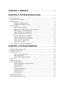
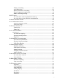
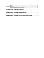
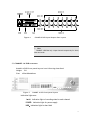
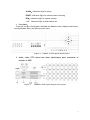
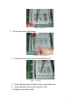
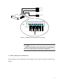
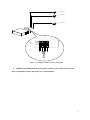
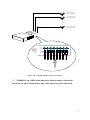
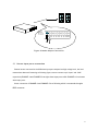
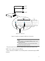
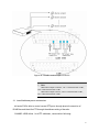
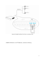
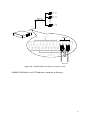
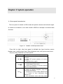
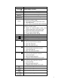
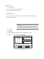
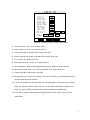
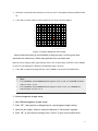
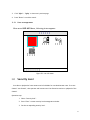
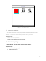
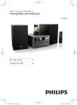
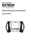
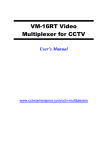
ICRealtime DVR
User’s manual
CHAPTER 1: PREFACE..........................................................................4
CHAPTER 2: SYSTEM INSTALLATION ........................................5
2.1 ACCESSARY LIST ................................................................................................. 5
2.2 OPERATION ENVIRONMENT ................................................................................... 5
2.3 APPEARANCE ..................................................................................................... 6
Channel 8 DVR structure ........................................................................ 6
CHANNEL 16 DVR structure .................................................................... 8
2.4 INSTALLATION .................................................................................................. 10
Hard disk Installation ........................................................................... 10
CHANNEL 4/8/16 Video input ports connection........................................... 12
Video output ports connection............................................................. 14
Audio input ports connection............................................................... 15
Audio output port connection.............................................................. 18
Sensor input ports connection ............................................................. 19
Alarm output ports connection ............................................................ 21
Pan/Tilt/Zoom ports connection............................................................ 23
Ethernet port connection..................................................................... 27
Start the recorder ................................................................................ 28
2.5
Network software installation ............................................................. 29
CHAPTER 3 SYSTEM OPERATION............................................... 30
3.1 FRONT PANEL INTRODUCTION .............................................................................. 30
3.2 REMOTE CONTROLLER ....................................................................................... 33
3.3 WINDOW DISPLAY.................................................................................................. 35
Split-window definition ....................................................................... 35
OSD information................................................................................... 37
Menu and window interface................................................................. 38
3.4 LOGIN ............................................................................................................ 40
3.5 KEYPAD AUTO-LOCK .......................................................................................... 42
3.6 SYSTEM MANAGEMENT ....................................................................................... 42
System parameter configuration ......................................................... 42
Disk Management.................................................................................... 45
System reset......................................................................................... 46
Display adjustment .............................................................................. 46
Language Selection ................................................................................. 47
Time setting ......................................................................................... 47
Version Query ......................................................................................... 47
3.7 RECORDING SEARCH .......................................................................................... 48
3.8 RECORD PARAMETER SETTING .............................................................................. 49
1
Timing recording .................................................................................. 50
Alarm Recording ..................................................................................... 52
Motion detection recording ................................................................. 54
Record segment length setup............................................................... 55
Audio recording setting........................................................................ 56
3.9 PTZ SETUP ..................................................................................................... 56
Pan/Tilt/Zoom control parameter setting ............................................. 57
Pan/Tilt/Zoom Preset positions management ........................................ 57
3.10 VIDEO CHANNEL SETTING ................................................................................. 58
3.11 COMMUNICATION SETUP ................................................................................... 60
Network parameter setup........................................................................ 60
Serial port setup..................................................................................... 61
3.12 SYSTEM RUNNING LOG ..................................................................................... 62
System log ............................................................................................ 62
Alarm log.............................................................................................. 63
3.13 USER MANAGEMENT ...................................................................................... 64
Security level................................................................................................ 64
On-line user inquiry ............................................................................. 65
Password modification ......................................................................... 65
Key lock ................................................................................................ 66
3.14 PARAMETER DATA MANAGEMENT ......................................................................... 66
Save current parameter ....................................................................... 67
Restore factory settings....................................................................... 67
Vidio Data Backup ................................................................................ 68
3.15 MONITORING CONTROL .................................................................................... 68
Window splitting .................................................................................. 68
Video auto-switching............................................................................ 68
Image freezing ..................................................................................... 69
Change focused channel....................................................................... 69
Audio monitor ...................................................................................... 69
3.16 CONTROL OF PAN/TILT/ZOOM .......................................................................... 70
Pan/Tilt/Zoom control ........................................................................... 70
Lens control ......................................................................................... 70
3.18 RECORDING CONTROL ...................................................................................... 71
Manual recording ................................................................................. 71
Stop recording...................................................................................... 72
3.19 PLAYBACK CONTROL ........................................................................................ 72
Playback ............................................................................................... 72
Slow playback ....................................................................................... 73
Stop playback ....................................................................................... 73
Frame playing ...................................................................................... 74
Forward ................................................................................................ 74
Backward .............................................................................................. 74
Previous................................................................................................ 75
2
Next...................................................................................................... 75
3.20 ALARM CANCEL .............................................................................................. 75
Remote controller address selection ................................................... 75
CHAPTER 4. SPECIFICATIONS ...................................................... 77
APPENDIX1: RECORD PARAMETER........................................... 77
APPENDIX2: OPERATION ATTENTION LISTS ..................... 78
3
Chapter 1: Preface
Thank you for choosing our stand-alone MPGE4 Digital Video Recorder
System! Please read carefully before proceeding on.
l
Only our MPGE4 series DVR users will find this manual instructive with
their operation.
l
Contents described in this manual can be adapted to our CHANNEL 4,
CHANNEL 8 and CHANNEL 16 MPGE4 DVRs.
l
Operation on CHANNEL 8 is as same as on the CHANNEL 4, except that there are no keys
to control functions of 9 images splitting and 6 images splitting on the panel of CHANNEL
4, Keys to control functions of 13 images splitting、16 images splitting are added on
CHANNEL 16 on the basis of CHANNEL 8
l
We take CHANNEL 16 as an example for description in this manual.
l
Please kindly read this manual carefully and follow the instructions to set
up the system before operation.
l
This manual is written according to V1.1 of the mainboard sortware which
is announced on 04/12/01.
l
Any further inquiries please contact us or our authorized agents/dealers.
Contents are subject to change without notice when upgraded. Please
turn to our website for any latest information and tech-support
concerning products&operations.
4
Chapter 2: System Installation
2.1 Accessary List
1. Please make sure all the items listed as follows are included in when you unpack
this unit.
Table1 DVR accessory list
NO.
Accessories
1
1
POWER CABLE
2
3
4
5
6
7
8
9
10
Remote controller
5# battery supply for remote controller
Screws to fix HDD
HDD connection cable
RJ45 cable
Serial cable
Operator’s manual
Software CD
Warranty card
QC passed certificate
Package list
DB25
11
12
13
Quantity
1
2
1
4
1
1
1
1
1
1
1
1
2. Please contact your agent if anything missed.
2.2 Operation Environment
1. Our DVR operation requirements are descripted as follows:
Table2 DVR operation enviroment
Item
ELECTROMAGNETISM
TEMPERATURE
Description
C series DVRs are complied with National
Electromagnetism Radiation Standard and
guarantee no harm to human body
0℃ ~ 55℃
5
Humidity
Air pressure
Power supply
Power consumption
10% ~ 90%
86kpa ~ 106kpa
110 VAC, 60HZ
40W
2. Please kindly note the following issues during installation & operation of the machine:
l
l
l
l
l
l
Do not expose directly under sunshine, keep away from heat sources and high
temperature sites.
Do not leave in humid places and never touch with wet hands.
Never spill liquid of any kind on the unit to prevent short circuit and fire.
Please place steady and don’t put any other equipments on the unit.
Avoid install in places shaking violently.
Never use the unit when power supply is far beyond normal level
2.3 Appearance
& Channel 8 DVR structure
CHANNEL 8 DVR front panel layout is as following described.
Height: 2U
Size
:
430x100x440mm
Figure 1
CHANNEL 8 DVR front panel layout
Indication light zone:
1-8:Indication light of recording state for each channel
POWER:Indication light for power supply
HDD:Indication light for hard disk
ALARM:Indication light for alarm
REMOT: Indication light for remote control
RUN:Indication light for system running
6
1. Front Panel:
From left to right: the keypad is devided into Numbers zone, display control zone,
record/playback zone, and system control zone.
Figure 2
CHANNEL 8 DVR keypad distributions
% Note
Keys for 6-screen splitting and 9-screen splitting are not
available on the front panal of CHANNEL 4
2. Connection ports on the back
Figure 3
CHANNEL 8 DVR back panel layout
3. Audio, video, PTZ control and alarm input/output ports connection of CHANNEL 8
DVR
7
Figure 4
CHANNEL 8 DVR Input/Output Port Layout
% Note
CHANNEL 4 DVR has only 4 input channels respectively for alarm,
video and audio.
& CHANNEL 16 DVR structure
CHANNEL 16 DVR front panel layout is as following described.
Height: 2U
Size: 430x100x440mm
Figure 5
CHANNEL 16 DVR front panel layout
Indication light zone:
1-16:Indication light of recording state for each channel
POWER:Indication light for power supply
HDD:Indication light for hard disk
8
ALARM:Indication light for alarm
REMOT: Indication light for remote control receiving
RUN:Indication light for system running
+10: Indication light for add number ten
1. Front Panel:
From left to right: the keypad is devided into Numbers zone, display control zone,
record/playback zone, and system control zone.
Figure 6
CHANNEL 16 DVR keypad distributions
2. Audio, video, PTZ control and alarm input/output ports connection of
CHANNEL 16 DVR
Figure 7
CHANNEL 16 DVR Input/Output Port Layout
9
2.4 Installation
& Hard disk Installation
Installation steps:
1. Dismantle the upper part of the HD bracket.
Figure 8 up part of HD bracket dismantle
2. Set the HD to work mode required, for example: master HD or slave HD.
3. Install the HD
Figure 9 Insert the HD
4.
Fix the HD
10
Figure 10 Fix HD
5.
Fix the upper part of HD bracket.
Figure11 Fix the HD Bracket
6.
Install HD into the upper part of the bracket and fix it.
Figure 12 Fix HD
7.
Connect HD data cable with IDE interface on the main board.
8.
Connect HD data cable with IDE interface on HD.
9. Plug ATX power cable into HD
11
% Note:
One IDE interface supports Max. 2 HD only, one “Master” and the
other “slave”, You have to set it as “Master” mode when one HD is
required, otherwise it cannot be recognized by the system.
& CHANNEL 4/8/16 Video input ports connection
1.
CHANNEL 4 has 4 BNC video input ports at the back panel for direct connection
with cameras.
CAMERA1
CAMERA2
CAMERA4
VIDEO
INPUT
Figure 13 CHANNEL 4 camera connecting
2.
CHANNEL 8 has 8 BNC video input ports at the back panel for direct connection
with cameras as following described.
12
Figure 14 CHANNEL 8camera connecting
3.
CHANNEL 16 has 16 BNC video input ports at the back panel for direct
connection with cameras.
13
CAMERA1
CAMERA2
CAMERA16
VIDEO
INPUT
Figure 15 CHANNEL 16 DVR camera connecting
$ Note:
When it is unnecessary to use all the inputs, it is recommended to
start from 1# video input port for easy system configuration,
& Video output ports connection
Video output port is in the middle part of the back panel, which is used to connect the recorder with
monitor.
14
Figure 16 Video Output Connection
&
Audio input ports connection
Audio/Video recording synchronization is available for DV series DVR .
1.
CHANNEL 4 has 4 BNC audio input ports that are used to collect audio sources on
site which corresponds to each video input port on the back panel.
15
microphone1
microphone2
microphone4
Audio
Input
Figure 17 CHANNEL 4 Audio Input Connection
2. CHANNEL 8 has 8 BNC audio input ports that are used to collect audio sources on site
which corresponds to each video input port on the back panel.
16
Figure 18
3.
CHANNEL 8 Audio Input Connection
CHANNEL 16 has 16 BNC audio input ports that are used to collect audio
sources on site which corresponds to each video input port on the back panel.
17
microphone1
microphone2
microphone16
Audio
Input
Figure 19
&
CHANNEL 16 Audio Input Connection
Audio output port connection
CHANNEL4/8/16 provides one audio output port for connection to sound boxes, on-site audio and
recorded audio data can be outputted through this port.
18
Figure 20 Audio Output Connection
&
Sensor input ports connection
External sensor connected to the DVR alarm input ports outputs low/high voltage level, low level
means alarm detected.Connecting as following figure, sensors connect to pin “Input” and “GND”
respectively.CHANNEL 4 and CHANNEL 8 has eight alarm input ports while CHANNEL 16 has sixteen
alarm input ports .
Sensor connection of CHANNEL 4 and CHANNEL 8 is as following which is connected through a
DB25 connector:
19
Figure 21 CHANNEL 4 and CHANNEL 8 DVR Sensor Connection
O Note:
Both CHANNEL 4 and CHANNEL 8 DVR provide 1 to 8
alarm input port(s).
12VDC power is provided for most sensors and alarm output
equipments for easier system construction
Two pins are used in the connection between sensor and DVR,One connects to the
ALARM
IN pin ,another connects the GND pin.
Sensor connection of CHANNEL 16 is as following which is connected through two DB25
connector:
20
Figure 22 CHANNEL 16 DVR sensor connection
&
Alarm output ports connection
CHANNEL 4 and CHANNEL 8 provide 3 groups alarm output ports and CHANNEL 16 provide 4
groups, with ” NO” and “NC” available for each alarm output.
CHANNEL 4 and CHANNEL 8 alarm output connection is as following which is connected through
a DB25 connector:
21
Figure 23 CHANNEL 4 and CHANNEL 8 alarm output connection
CHANNEL 16 provides 4 alarm output ports through two DB25 interfaces which is connected as
following:
22
Figure 24 CHANNEL 16 alarm output connection
% Note
When alarm output is inactive, “NC” is connected with “COM”,
“NO” is disconnected with “COM”;
When alarm output is active, “NO” is connected with “COM”,
“NC” is disconnected with “COM”;
&
Pan/Tilt/Zoom ports connection
M4 series DVR is able to control several PTZ ports through physical connection of
RS-485 bus and identifies PTZ through the address setting of decoder.
CHANNEL 4 DVR define 1 to 4 PTZ addresses, connected as following:
23
Figure 25 CHANNEL 4 DVR Pan/Tilt/Zoom connection wire
CHANNEL 8 DVR define 1 to 8 PTZ addresses, connected as following:
24
Figure 26
CHANNEL 8 Pan/Tilt/Zoom connection wire
CHANNEL 8 DVR define 1 to 8 PTZ addresses, connected as following:
25
Figure 27 CHANNEL 16 Pan/Tilt/Zoom connection wire
% Note
PTZ address in system is the same as the camera number,
namely,
Camera 1 has PTZ address of 1
Camera 2 has PTZ address of 2
…
Camera 16 has PTZ address of 16
PTZ address configurations have to follow the above rule.
26
&
Ethernet port connection
M4 series DVR provides one 10/100M Ethernet port connection to LAN or Internet directly.
CHANNEL 4 or CHANNEL 8 is connected to network as following:
Figure 28
CHANNEL 4 or CHANNEL 8 DVR Network Connection
CHANNEL 16 is connected to network as following:
27
Figure 29 CHANNEL 16 DVR Network Connection
&
Start the recorder
Before starting the recorder, please confirm:
1. Plug in power line of recorder;
2.Power on external equipments;
3.Push the power button at the front of the recorder;
4.Power indication lights on, with the following starting picture shown on the monitor.
28
Figure 30 System Starting
After the starting picture ends, video from cameras will be displayed on the
monitor. DVR enters into normal working mode for operation.
2.5 Network software installation
Network browser installation notification:
Network browser only support windows 2K/ windows XP
Installation Step:
Run the CD driver and follow the installation prompt to setup the program.
29
Chapter 3 System operation
3.1 Front panel introduction
The front panel of CHANNEL 16 DVR includes all operation buttons and indication lights
of CHANNEL 4 and CHANNEL 8, so we take CHANNEL 16 DVR as an example to introduce these
functions.
Figure 31
CHANNEL 16 DVR Operation Panel
From left to right, the front panel is divided into four function zones :
Numbers zone, window control zone, Record/playback zone, and System control zone.
Function key definition of front panel:
Key Name
REC
Stop
Play
Function
1.Activate manual recording of current
channel
2.Save PTZ preset position of current
channel
3.HDD directory repair
1.Stop recording of current channel
2.Stop playback operation
3.Place PTZ position of current channel
back to initial position
1.Activate playback of current channel
2. Back to normal playback from fast
forward & backward
3.Playback by frames under PAUSE mode
4. 3 levels of slow backward play
back(X1/2)
5. Pan horizontal move and stop under
30
pan control mode
Pause
Forward
Backword
Next
Previous
Enter
ESC
F
Menu
Direction
Direction
PAUSE CURRENT PLAYBACK
3 levels of fast forward playback
3 levels of fast backward playback
Jump to next recorded segment
Jump to previous recorded segment
1.Confirm key when in menu operation
or window prompt mode
2.Set/cancel motion detection areas
3. set mask area
4. P/Z、lens, iris and die state switching
1.Cancel key when in menu operation or
window prompt mode
2 . Back to menu/window state from
motion detection area setup state
3、log out the mask area setup mode
4、set or cancel mute mode
5、cancel bidirectional talking
Freeze picture of current channel
Cancel alarm output
Single channel auto-switching
Enter system menu mode
1.“Up”
2.Pan/tilt up direction control
3.move the lens near
4.Move the mask area up
1.“Down”
2.Pan/tilt down direction control
3.move the lens far
4.Move the mask area down
Direction
Direction
1.“Left”
2.Pan/tilt left direction control
3.Lens focus near
4.Move the mask area left
5.Playback data backward at *2,*4,*8
1.“Right”
2.Pan/tilt right direction control
3.Lens focus far
4.Move the mask area left
5.Playback data forward at *2,*4,*8
4 window splitting
6 window splitting
9 window splitting
13 window splitting
31
16 window splitting
+10
0
1
2
3
4
5
+10
1.“0”
1. “1”
2 . Switch from 9 window splitting to
camera1 single window
3 . Set camera1 as the main window
under 6 window splitting mode
4. Switch from 4 window splitting to
camera1 single window
5. Switch from 16 window splitting to
camera1 single window
6. Set camera1 as the main window
under 13 window splitting mode
7. display the mask area under video
mask area setup mode
1. “2”
2 . Switch from 9 window splitting to
camera2 single window
3 . Set camera2 as the main window
under 6 window splitting mode
4. Switch from 4 window splitting to
camera2 single window
5. Switch from 16 window splitting to
camera2 single window
6. Set camera2 as the main window
under 13 window splitting mode
7. identify the mask area under video
mask area setup mode
1. “3”
2 . Switch from 9 window splitting to
camera3 single window
3 . Set camera3 as the main window
under 6 window splitting mode
4. Switch from 4 window splitting to
camera3 single window
5. Switch from 16 window splitting to
camera3 single window
6. Set camera3 as the main window
under 13 window splitting mode
1. “4”
2 . Switch from 9 window splitting to
camera4 single window
3 . Set camera4 as the main window
under 6 window splitting mode
4. Switch from 4 window splitting to
camera4 single window
5. Switch from 16 window splitting to
camera4 single window
6. Set camera4 as the main window
under 13 window splitting mode
1. “5”
2 . Switch from 9 window splitting to
32
6
7
8
9
camera5 single window
3 . Set camera5 as the main window
under 6 window splitting mode
4. Switch from 16 window splitting to
camera5 single window
5. Set camera5 as the main window
under 13 window splitting mode
1. “6”
2 . Switch from 9 window splitting to
camera6 single window
3 . Set camera6 as the main window
under 6 window splitting mode
4. Switch from 16 window splitting to
camera6 single window
5. Set camera6 as the main window
under 13 window splitting mode
1. “7”
2 . Switch from 9 window splitting to
camera7 single window
3 . Set camera7 as the main window
under 6 window splitting mode
4. Switch from 16 window splitting to
camera7 single window
5. Set camera7 as the main window
under 13 window splitting mode
1. “8”
2 . Switch from 9 window splitting to
camera8 single window
3 . Set camera8 as the main window
under 6 window splitting mode
4. Switch from 16 window splitting to
camera8 single window
5. Set camera8 as the main window
under 13 window splitting mode
1. “9”
2 . Switch from 9 window splitting to
camera9 single window
3 . Set camera9 as the main window
under 6 window splitting mode
4. Switch from 16 window splitting to
camera9 single window
5. Set camera9 as the main window
under 13 window splitting mode
3.2 Remote controller
The remote controller is an accessory to enhance handy operation of digital video
recorder. All the setting and operation can be done through remote controller. Most
keypad functions of remote controller are as the same as the front panel. Please
33
refer to section“front panel” for detailed functional description.Special keys of
remote controller are explained below:
choice
?
1
2
3
4
5
6
7
8
9
0
P/Z
F
OK
Cancel
Menu
Save
Figure 32
Key Name
Choice
P/Z
Set
Save
Back
Set
Back
Remote controllers
Function
Select DVR to be controlled
Pan,lens,iris idle state switching
Set P/Z original position of current
channel
Save P/Z preset position of current
channel
Place P/Z back to original postion
34
3.3 Window Display
&
Split-window definition
M4 series DVR supports single window,picture in picture,4/6/9/13/16 window splitting .
35
Figure 33
Display modes
36
% Note
CHANNEL 4 DVR supports only single and 4 picture splitting
CHANNEL 8 DVR supports single and 4/6/9 picture splitting.
CHANNEL 16 DVR supports single and 4/6/9/13/16 picture
splitting.
& OSD information
Entire system picture displays as following:
General
2004-07-09
16:30:38
HDD size
Date
Audio output
Cam1
Cam2
Cam3
Current channel
Cam4
Cam5
Cam6
Camera NO.
Cam7
Cam8
Figure 34
Cam9
System picture display
The status display of Single channel is as following:
37
Figure 35
Channel display
& Menu and window interface
User interface of DV series DVR are composed of menu interface and window interface through
which user controls the system. Basic operation is described below:
1.Menu
Below shows basic menu format. Press “up” and “down” to move the cursor. Press”Enter”to
confirm your choice.
38
MAIN MENU
SYSTEM
PLAYBACK
PTZ SETUP
REPORT
RECORDER
CAMERA
NETWORK
USER INFO
DATA MANAGE
HINT:SYSTEM SETUP
Figure 36
Menus
2. Window
l
Below shows system window interface.
Figure 37 Windows Interface
l
Window operation is similar with the menu operation.
1. Press”up” and “down” to move the cursor.
2. Targets controllable in the window interface includes number input box, date input box, time input box,
selection box, etc.
39
3. The uncontrollable targets include characters, boundaries, and titles.
l Descrioption
Fig. 4 Window operation setting
TARGET
OPERATION
Data Input:
REMARKS
1.Input numbers
2.Press “Left” or “Right”
move the cursor
1. Input numbers
2.Press “Left” or “Right”
move the cursor
1. Input numbers
2.Press”Left” or “Right”
move the cursor
Press “Left” or “Right”
select terms
Date Input:
Time Input:
Selection Table:
Common
to
to
to
to
Selection Bar:
Press”OK” to confirm
current selection
OK/Cancel
Press “OK” to confirm your
selection
Cancel
Cursor is unmovable
when illegal date
inputted
Cursor is unmovable
when illegal time
inputted
your
In list box
Mostly shown on the
bottom
of
the
window
3.4 Login
l
Login by inputting your passwords.
The recorder has three password levels: Manager, Operator and Browser with Master at the top level
and Browser at the bottom. The security level will be verified according to the input password. If
passwords of different levels are the same, then most highest operation level is granted. Different
password level leads to different operation restrictions.
O
Note
1,The password consists of Max. 6 numbers, factory default
configuration is set as:
Manager---------333333
Operator----222222
Browser--------111111
2.If wrong password is inputed 3 times, DVR will produce a
beep..
40
l
Login steps:
1. Press any key, system will pop up a login dialogue box;
2. Input your password;
3. Press “OK” for your selection;
4. After password verification, system will remind you of your level after successful login.
Logi n Passwor d
Passwor d
******
OK
Cancel
Figure 38 User Login Interface
Successful login:
Logi n Success
O
Wel come- - - - - Manager !
OK
Figure 39 Login Successful
Unsuccessful login:
Passwor d Er r or
%
Your Passwor d i s i ncor r ect
Log on Fai l ed!
OK
Figure 40 Login Failed
41
3.5 Keypad auto-lock
Keypad auto-locking works after long-time operation vacancy. Re-logon is required for further
operation. Keypad auto-locking starts timing when no operation is done on the system, timing stops
when user operates the system.
When keypad auto locks, system pops up following message:
Keyboar d Lock
O
Do you r eal l y want t o l ock keyboar d ?
OK
Figure 41 Keyboard Auto Lock
3.6 System Management
&
System parameter configuration
Basic system parameter configuration are provided:
F
System recognition
F
Single channel auto-switching interval setting
F
Recorder overwrite mode select
F
Power-on auto-recording select
F
Video format select
F
Keypad auto-locking interval setting
F
Screen show select
F
Buzzer select
F
Pre-recording select
F
Manual recording quality select
F
I frame interval setting
F
VGA output resolution setup
42
F
External trigger source for auto-switching(Only available in
CHANNEL 2 DVR )
F
Stream type select
F
Alarm switch select
F
Frame rate select
operation steps:
1. Click SYSTEM Management on the menu.
Figure 42 System Parameter Setup Menus
2.
Click System paramter.
43
Figure 43 System Parameter Setup
3.Configure parameter as required.
Detailed function description of each parameter shows in the following table.
Table 3 system parameter configuration description
Items
Description
System
Identification
Single
channel
auto-switching
interval
Power
on
auto-recording
select
Recorder overwrite
mode select
Define the ID of DVR for control
through remote controller
Define
single
channel
auto-switching interval
Video format
Keypad
auto-lock
interval
Screen show
Select the current video format
Length of idle time before
keypad auto locks
Whether to display the channel
title and other icon or not
Buzzer
on/off
when
alarm
triggered
Startup pre-recording or not
Select manual recording image
quality level
Define record I-frame interval
Buzzer
Pre-recording
Image quality
I-Frame interval
Remarks
>0s
Auto-recording or not when the
system is powered on
Yes or No
Auto/manual overwrite mode
select when the HD is full
Auto: System overwrites
the most earliest records
without notice.
Manual: System notifies
user when HD full.
PAL or NTSC
≥5s
All,cancel,title
and
status can be selected
Yes or No
Yes or No
Bad/normal/good/better
/best
Suggestion: use default
44
VGA
resolution
setting
Trigger source for
video switching
Stream type
Alarm switch
Frame Rate
value 00
800*600 or
1024*768
Setup external alarm input as Only available in CHANNEL
trigger
source
for
video 2 DVR
switching
Define the stream of manual Yes or no
record variable or not
Define single channel display or Yes or no
not when the channel is alarm
recording.
manual
record
frames(full FULL、1/2F、1/4F、1/8F or
means 25fps)
1/16F
Setup VGA output resolution
% Warning:
System time is extremely important to a smooth
running of the whole system. Exiting from all other
functions are suggested when system time.modification is
necessary, otherwise it’ll result in mistake in recording.
4. Choose “OK” to confirm your setting; Choose “Cancel” to give up.
& Disk Management
Query and management of HD information is provided. Formatting is required before a new HD can
be used after installation.
Operation step:
1. Select Disk Information.
2.“Disk Information” window will popup, information of all connected HD is
displayed.
3.When formatting is required, move the select bar to the HD wanted and press”OK” key. Formatting
status will be displayed on the screen.
4.When repairing the HD catalog is required, move the select bar to the HD wanted and press
“Record”key
45
% Warning:
HD formatting will delete all the stored data
5.
Choose”PgUp” or “PgDn” to view all the information.
6.Choose”Return” to close “Disk Information” window.
&
System reset
User may use this function to reset the whole system.
Operation step:
1.Click System Reset.
2.A dialogue box will popup to make sure the operaton.
3.Press ”OK” to reset system; Press ”Cancel” to give up.
& Display adjustment
Video parameter of each current channel can be adjusted separately, with values ranging from 0-99.
Adjustable figure is displayed below:
Figure 44 video parameter adjust
46
$ Note:
Video adjusted is the focused channel. Only in live
video monitor mode can channel 1 be adjusted.
If Channel 1 is under playback mode, Its contrast,
brightness and color cannot be adjusted.
The saturation parameter is not realized now.
Operation step:
1.
Move cursor to the desired channel.
2.
Click Picture adjust.
3. Select different item using ”Up” and “Down”; Change numbers using ”Left” or “Right”.
4.
Press ”Return” to finish the adjustment.
& Language Selection
User can select English or Chinese to operate the system.
Operation step:
1.
Select Language Selection.
2.
Press “OK”, use “UP” and “DOWN” keys to select.
3. Press ”BACK” button to end the selection.
& Time setting
Set the system time of recorder.
Operation step:
1. Select “Time setting”.
2. Press “OK” to display current system time, set new time using number keys.
3. Press “OK” to activate new time; Press “Cancel” to give up modification.
&
Version Query
Software version can be queried from system menu.
47
Operation step:
1. Select System Version.
2. Press “OK”, version information will be displayed.
3. Press ”OK” again to close the window.
3.7 Recording search
Three methods are provided to search recorded data, based on Time/Channel/Event separately,
Combined search is also available.
% Warning:
Max..5000 records are available for each search.Other
records can be searched by changing search conditions
Operation step:
1. Select playback.
2. Video search dialogue will popup for users to input search conditions.
Channel No. Set at “0” means searching all the channels.
VI DEO SEARCH
Camer a No.
05
Fr om
2004- 07- 12 11: 24: 00
To
2004- 07- 12 12: 00: 00
Event Vi deo
No
HI NT: " 00" means sear ch al l channel s
Ok
Figure 45
Cancel
Vidio Search window
48
$ Note:
When event record search is selected, only event
recording data is searched. Else all type of datas are
searched.
Event recording include 3 types:
1.External alarm event
2.Motion detection event
3.Timing event
3. Press ”OK” to start searching; Press”Cancel” to stop
4. Dialogue box will popup to show the search result.
5. Move curcor to select record data. Use “PgDn” or “PgUp” to view the recording data page by
page.
6. Click “OK” to play back the records selected.
7. Please refer to section 16 for control during playback.
$ Note:
During playback, when current segment is over,
system will continue playback by jumping to the next
segment.
3.8 Record parameter setting
Users select “record parameter setting” through the menu display as following.
49
figure 46 Record parameter setting menu
&
Timing recording
According to the preset time, system will automatically record. Parameters like record
quality,record frame,record stream and record interval of time can be setted individually for each
channel.
Operation step:
1. Select “Timing Record Setup”.
2.
Press “OK”, enter timing record parameter configuration window. Press”Up” or “Down” to move
the curcor and press “Left” or“ Right” to select the Parameters.
50
TI MER REC.
Channel 01
Basi c
Ful l
CBR
SUN 00: 00
24: 00
Of f
00: 00
24: 00
Of f
MON 00: 00
24: 00
Of f
00: 00
24: 00
Of f
00: 00
24: 00
Of f
00: 00
24: 00
Of f
WED 00: 00
24: 00
Of f
00: 00
24: 00
Of f
THU 00: 00
24: 00
Of f
00: 00
24: 00
Of f
FRI
00: 00
24: 00
Of f
00: 00
24: 00
Of f
SAT
00: 00
24: 00
Of f
00: 00
24: 00
Of f
ALL
00: 00
24: 00
Of f
00: 00
24: 00
Of f
TUE
Al l
Ok
Figure 47
Cancel
Timer Recorder parameters setup
3.
Channel No.: from 1 to 16.
4.
Record quality: Bad/normal/good/better/best; default value:normal;
5.
Record frame:Full,1/2F,1/4F,1/8Fand 1/16F,default value:Full
6.
Stream type:CBR or VBR. defaut value:CBR.
7.
The date of record time is Sunday, Monday, Tuesday, Wednesday, Thursday, Friday, Saturday or all.
Two record intervals can be set for each day. “all” indicates record that is carried out each day
according to the setted time.After setting every interval time, option bar must be set “on” to
make the setting active. Default value: all timing recordings are turned off.
8.
If all of the channels have the same timing recording parameters, after setup of one channel,
press “all” below the memu, system will hint as following.
Figure 48 “all” hint
51
9. After set the timing record parameters according to your requirement, press “Ok”.
10. Press ”OK” to make current parameter settings effective; Press ”Cancel” to give up the
modification.
$ Note:
As to CHANNEL 4, channel selection is only available
from No.1 to No. 4
As to CHANNEL 8, channel selection is available from
No.1 to No. 8.
As to CHANNEL 16, channel selection is available from
No.1 to No. 16
&
Alarm Recording
According to alarm input signals generated by external sensors, system can start auto-recording
and output related alarm signals. Users can setup following parameters: alarm input port、alarm
output port、alarm time length、alarm recording time length、P/T/Z action、recording channel、
recording quality、recording interval. Operation step:
1.
Select Alarm-Rec Setup.
2.
“Alarm-Rec Setup “ dialogue box pop up. Press”Up” or “Down” to move the cursor for setting,
press”Left” or “Right” to select terms and input parameters. The menu looks like following:
52
Figure 49 Alarm Recording parameter setup menu
3. Alarm input port: from 1 to 16. default value: 1.
4. Alarm output port: from 1 to 4. default value: 0.
5. Alarm time length: from 000 to 999. default value: 060.
6. Alarm recording time length: From 000 to 999. default value: 060.
7. P/T/Z action: 00. default value: 00.
8. Recording channel no.: from 1 to 16. default value: 1.
9. Recording quality: Bad/normal/good/better/best; default value:normal;
10. Recording frame rate:. Full,1/2F,1/4F,1/8Fand 1/16F. default value:Full
11. Stream type:CBR or VBR. defaut value:CBR.
12. Recording interval 1 and 2: two intervals can be set for each day, only during these intervals
external alarm inputs are detected.
13. If all of the channels have the same alarm recording parameters, after setup of one channel,
press “all” below the memu, system will hint “current channel parameter is applied to all
channels”, press “ENTER” all channels will set these parameters automatically.
14. Press ”OK” to make current parameter settings effective; Press ”Cancel” to give up the
modification.
53
$
Note:
$
For CHANNEL4 and CHANNEL8 alarm input is from 1 to 8, for CHANNEL16 alarm
input is from 1 to 16.
$
For CHANNEL4 and CHANNEL8 alarm output is from 1 to 3, for CHANNEL16
alarm output is from 1 to 4.
$
No alarm output if alarm time length is “0”;
$
If recording channel is set to 0, it means record all channels.
$
No P/T/Z function if P/T/Z set at “0”
& Motion detection recording
By detecting the motion in the video, recorder can start motion detection recording. Parameters
like sensitivity of motion detection, motion detection zone, P/T/Z movement, alarm recording
duration, record quality, alarm output port, alarm output duration can be configured individually.
Opeartion Step:
1.
Select Motion-Rec. Setup.
2.
Press “OK” to popup a dialogue box for parameter setting. Press”Up” or “Down” to move the
cursor for setting, press”Left” or “Right” to select terms and input parameters. The menu looks
like following:
Figure 50 motion detection recording parameter setup menu
Sensitivity adjustment and motion detection zone setup are described below in detail:
54
3.
Sensitivity: motion detection sensitivity is from 0 to 99, 0 is the highest sensitivity. Default value :
50.
4.
Click ”set”on certain channel, motion detection zone setup interface appears.
1
2
3
4
5
6
7
8
9
10
11
12
1 2 3 4 5 6 7 8 9 1 1 1 1 1 1 1
0 1 2 3 4 5 6
Figure 51 motion detection area setup
Motion detection setting is only available in the green area, in which green area
represents the setted area. White area represents the not setted area.
Move the cursor using up/down/right/left keys. Press “OK” for area setup /clearance. Press ”Cancel”
to return to the dialogue box. Maximum 192 individual areas can be set.
5.
Press ”OK” to make all settings effective. Press “Cancel” to give up all the modification.
$
Note:
$
For CHANNEL4 and CHANNEL8 alarm input is from 1 to 8, for CHANNEL16 alarm
input is from 1 to 16.
$
For CHANNEL4 and CHANNEL8 alarm output is from 1 to 3, for CHANNEL16
alarm output is from 1 to 4.
& Record segment length setup
1. Select Record segment length setup.
2. Press “OK”, then pops out a dialogue box for record segment length setting.
3. Input the new length, effective values are between 5~240 seconds/ segment.
4. Press “OK” to activate new settings; Press “Cancel” to give up the modification.
55
& Audio recording setting
Audio recording companion to video recording can be selected for each channel.
$ Note:
Audio data has to be included in the recording if
remote on-site sound surveillance is needed. As.HD
capacity is considered, we suggest not select audio
recording when audio is not used,
Operation Step:
1. Click “Audio recording setting”.
2. Move the cursor using “Up” and “Down”; Select item using ”Left” or “Right”.
3. Press ”OK” to save the setting; Press ”Cancel” to give up current modification.
3.9 PTZ setup
Figure 52 P/T/Z setup menu
56
&
Pan/Tilt/Zoom control parameter setting
According to the P/T/Z type, user can setup P/T/Z parameters such as P/T/Z control protocol,
P/T/Z communication rate and P/T/Z connetion.
Operation step:
1. Select P/T/Z Setup.
2. Press “OK” to enter P/T/Z parameter setup window.
3.
Move the cursor using “Up” and “Down”; Select item using ”Left” or “Right”.
4.
Press ”OK” to activate new configurations; Press ”Cancel” to give up modification.
$ Note
Max 4 P/T/Z channels can be set in CHANNEL4.
Max 8 P/T/Z channels can be set in CHANNEL8.
Max 16 P/T/Z channels can be set in CHANNEL16.
&
Pan/Tilt/Zoom Preset positions management
P/T/Z preset positions are used in alarm recording and motion detection recording, when needed
P/T/Zs can be directed to the preset positions. Preset position management function includes query
and deletion of preset positions.
Operation step:
1. Select P/T/Z preset.
2. Press “OK” to enter preset position management window
3. Move the cursor using “Up” and “Down”; Select item or input parameters using ”Left” or
“Right”.
4. Channel no.: select the channel to be managed.
5. Preset position: select the preset position to be managed.
6. Call: place the P/T/Z of current channel to current preset position.
7. Original position: place the P/T/Z of current channel to its original position.
8. Delete: delete current preset position.
57
9. Status: show whether current preset position was set or not.
10. Return: return to its top layer menu.
11. Auto circular monitoring: under Pan control mode press “Play” to start auto circular
monitoring, press again to stop.
$ Note
P/T/Z preset position setup and original
position setup will be described in section 16
“ P/T/Z control”.
3.10 Video channel setting
Parameters like connection, display position, shelter zone, P/T/Z protocal can be configured for
each channel.
CAMERA SETUP PAGE
Channel No
01
Enabl e
On
Mask Ar ea
Set
Mask Act i ve
On
Noi se Mode
Nor mal
PI Z Pr ot ocol
PELCO- P2
Rec. Reser ve
000
Channel Name
Camer a0001
Al l
Ok
Days
Cancel
Figure 53 video channel connection setup menu
Operation step:
1.
Select Video channel setting
2.
Press “OK” to enter video channel setting window.
58
3.
Move the cursor using “UP” and “DOWN”. Modify parameters
using number keys or “RIGHT”/”LEFT”.
4.
Channel no.: select the channel to be controlled.
5.
Connection: whether to display current channel or not.
6.
Shelter zone: setup the area to be masked of current channel.
7.
Shelter active: whether to activate the mask area of current
channel or not. Default value: no.
8.
Low noise mode: function not realized now.
9.
P/T/Z protocol: communication protocol between DVR and
external P/T/Z. default value: PELCO-P1.
10. Recording reserved when overwrite: when the disk is full,
records of current channel among days setted here won’t be
deleted when overwrite.
11. Channel name: display current channel name
12. If all of the channels have the same video channel parameters,
after setup of one channel, press “all” below the memu,
system will hint “current channel parameter is applied to all
channels”, press “ENTER” all channels will set these
parameters automatically.
13. Press ”OK” to activate new configurations; Press ”Cancel” to
give up modification.
Shelter zone setup operation step:
When enter video area setup mode, following picture appears:
59
Figure 54 mask area setup
a)
Use direction key to move whole area or adjust area size.If user controls the start position
then move the area; If user controls the end position then adjust the area size.
b)
Press number key “1” and “2” to show its outline or fill the whole area.
c) Press “OK” to change start position or end position; Press “Cancel” to quit area setup
mode.
& Note
When applying “all”, the shelter zone setup doesn’t apply to all
channels, it needs to be set individually for each channel.
3.11 Communication setup
Communication setup includes two parts: Network parameter setup and serial port setup.
& Network parameter setup
Operation step:
1. Select Network parameter on the main menu.
2. Press “OK” to enter network parameter setup window.
60
3. Move the cursor using “UP” and “DOWN”. Modify parameters
using number keys or
“RIGHT”/”LEFT”.
Net wor k Set up
I P Addr ess
192. 168. 123. 230
Subnet Mask
255. 255. 255. 000
Gat eway
000. 000. 000. 000
Ser ver Por t
2000
Moni t or Pr ot ocol
TCP
Al ar m cent er I P
192. 168. 123. 252
Al ar m Por t
4000
Al ar m Enabl e
On
Li nk Speed
Aut o Mode
OK
Figure 55
Cancel
Network Parameter setup
4. Press ”OK” to save, press “Cancel” to give up modifications.
& Serial port setup
Baud rate setup: default value 2400bps
Data width: 8bits
Stop bit: 1bit
Checksum: none
& Note:
Never set the recorder and gateway IP address as 255
255 255 255;
Never set service port number as “0”
Re-start the recorder to make modification valid.
61
3.12 System running log
When enter SYSTEM LOG Menu, following picture appears:
picture 56 system log menu
&
System log
Main system events are recorded in system log. Records are kept in time sequence. When the
occupation has 100 system logs, the most earliest event will be overwrited.
Operation step:
1. Select System log
2. Press “Enter” to view current system log information.
3. Click ”PgDn” / “PgUp” to view next/ previous page.
4. Press ”Return” to end the search.
62
Syst em Log
No.
Descr i pt i on page01/ 01
Ti me
1
2002- 11- 29 11: 29: 34 Syst em st ar t ed
2
2002- 11- 29 11: 29: 34 [ Manager ] l ogi n
3
No Log
4
No Log
5
No Log
6
No Log
7
No Log
8
No Log
9
No Log
10
No Log
Pr ev
Next
Ret ur n
Figure 57 system log display
& Alarm log
Alarm events are recorded in alarm log. Records are kept in time sequence. When the occupation has
100 alarm logs ,the most earliest event will be overwrited.
Operation Step:
1. Select Alarm log.
2. Press “Enter” to view current alarm log information.
Event Log
No.
Descr i pt i on P01/ 01
Ti me
1
2002- 11- 29 11: 29: 34
Cam: 5 get si gnal
2
2002- 11- 29 12: 29: 34
Cam: 2 Vi deo Lost
3
No Al ar m Log
No Al ar m Log
5
No Al ar m Log
6
No Al ar m Log
7
No Al ar m Log
8
No Al ar m Log
9
No Al ar m Log
10
No Al ar m Log
Pr ev
Next
Ret ur n
Figure 58 event log display
63
3.
Click ”PgDn” / “PgUp” to view next/ previous page.
4.
Press ”Return” to end the search.
3.13
User management
When enter USER INFO Menu, following picture appears:
Figure 59 user info menu
&
Security level
Live video or playback of some camera can be forbidden for non-administrater users. If set one
channel “not allowed”, then operator and browser won’t be allowed to monitor or playback of the
channel.
Operation step:
1. Select “Security level”.
2. Press “Enter” to enter security level management window.
3. Set the corresponding security level.
64
4. Press “Return” to end the setup.
&
On-line user inquiry
Remote connected user can be inquiried and forced disconnected.
Operation Step:
1. Select “On line user”.
2. Press “OK” to enter on-line user information window.
3. Move selection bar using ”Up” and “Down” keys. Press ”OK” to disconnect the selected user.
Confirmation dialogue box will pop up as following.
4. Press ”OK” to disconnect, press ”Cancel” to give up.
Di sconnect Remot e User
% Do You Want To Di sconnect
The Remot e User ?
OK
Figure 60
Cancl e
disconnect remote user
5. Select ”Return” to end current inquiry.
&
Password modification
Password levels that can be modified are determined by the current user security level. The
recorder has three password levels as administrator, operator, and browser. Administrator can modify
all passwords, operator can modify passwords of opertator and browser, browser can only modify
password of browser.
Operation step:
1. Select “Password modification”.
2. Press “OK” to enter password modification window.
65
3. Input password with number keys. Press ”OK” to activate new passwords, press ”Cancel” to give
up the modification.
&
Key lock
Key lock function is provided to prevent illegal user from entering system.
Operation step:
1. Select Key lock.
2. Press “OK” to enter confirmation dialogue box.
3. Press “OK” to lock the keys, press ”Cancel” to give up.
$ Note:
The key lock function will be performed automatically
after long-time absence. Please refer to chapter ”auto-key
lock”. Manual key lock is also available.
3.14 Parameter data management
When enter DATA MANAGE Menu, following picture appears:
66
Fiagure 61 DATE MANAGE Menu
&
Save current parameter
Only after this operation will current system parameters be saved into system internal flash.
Otherwise, the recorder will lose the modified parameters when it powers down.
Operation step:
1. Select “Save current parameter”.
2. Press “OK” and system will notify when successful.
&
Restore factory settings
Factory default settings can be restored when needed.
Operation Step:
1. Select “Restore factory settings”.
2.
Press “OK” to confirm.
67
& Vidio Data Backup
Video data stored in harddisk can be backuped to external USB devices through USB interface
Operation step:
1.Select “Video data backup”.
2.Press “Enter”, backup search condition window will popup.
3.Input the backup conditions, press “OK” to confirm.
4 When the search results popup, press “backup” to start copy.
3.15 Monitoring control
&
Window splitting
Single video window or split-window can be displayed.
1. Split-window -> single window
According to the split mode, press the corresponding number key to display the single video
window. Please refer to Chaper “Basic Display” for key definitions.
2. Single window - > Split-window
Press split key to enter split-window mode.
&
Video auto-switching
Single video can be auto displayed channel by channel. Please refer to “System parameter setup”
for auto-switching interval setup.
Operation step:
1. Press”
icon”
2. Press ”
” under non auto-switching mode, system will enter auto-switching mode with an
” displayed on the left bottom corner of the screen.
” to stop auto-switching when already in auto-switching mode.
68
&
Image freezing
“Image freezing” is used to freeze current video for detail analysis when in live monitoring mode.
Other functions such as recording are not affected by freezing.
Opeartion Step:
1. Freeze current video channel by pressing ”F”, with an icon “F” shown on the left bottom
corner of the channel.
2.When in freeze mode press ”F” again to return to normal mode, icon ”F” disappeared.
$ Note:
The recorder will automatically return to the normal
running mode if you use the function of Image
auto-switching
& Change focused channel
Current focused channel has a selection bar on the channel, next operations such as start recording,
P/T/Z operation, picture freeze, video adjust etc are only effective to this channel. Focused channel
can be changed through direction keys.
Operation step:
a)
Press ”Up” or ”Down” to move the selection bar.
b)
Channel with the selection bar on the bottom is the current channel.
& Audio monitor
On-site sound can be monitored through the recorder. Only one channel can be monitored at one
time. Sound of the focused channel is outputted.
1. Press ”
”on the Remote controller or “ESC” on the pannel to enter mute mode and disable
system sound output.
2. Press ”
”on the Remote controller or “ESC” on the pannel again to enable system sound
output.
69
3.16 Control of Pan/Tilt/Zoom
& Pan/Tilt/Zoom control
P/T/Z can be moved up/down or left/right under control. P/T/Z preset positions and initial
position can be setup.
Operation guide:
1. On channel configured with P/T/Z connected, press”P/T/Z”(on remote controller) or
“Enter” (on panel).
2.
System enters P/T/Z control mode, with an icon ”
of
” displayed on left bottom corner
the channel.
3. Press”up” and “down” to adjust P/T/Z vertical angle.
4. Press”left” and “right” to adjust P/T/Z horizontal angle.
5. Press ”recording” on panel or “Save” on remote controller to save current P/T/Z
position as preset position.
6. Press ”F” on panel or “setup” on remote controller to save current P/T/Z position as
initial position.
7. Press ”stop” on panel or “Return” on remote controller to turn P/T/Z back to initial
position.
8. Re-press ”P/T/Z” or “Enter” to enter lens control mode. Please refer to the next section
for details.
& Lens control
Lens control includes zoom in/ zoom out, foculizing/dilating, preset positions setup, initial
position setup.
Operation step:
1.Press ”P/T/Z”(using remote controller) or “Enter”(using front panel) under P/T/Z control
mode.
70
2. System enters lens control mode with an icon ”
” displayed on left bottom corner of
the channel.
3. Press”up” and “down” to zoom lens near or far.
4. Press”left” and “right” to move lens focus near or far.
5. System enters iris control mode when press “Enter” under lens control mode, with an
icon “
” displayed on left bottom corner of the channel.
6. Press”up” and “down” to set the iris value.
7. Press ”recording” on panel or “Save” on remote controller to save current P/T/Z
position as preset position.
8. Press ”F” on panel or “setup” on remote controller to save current P/T/Z position as
initial position.
9. Press ”stop” on panel or “Return” on remote controller to turn P/T/Z back to initial
position.
10. Re-press ”P/T/Z” on remote controller or “Enter” on front panel to quit iris control mode
and enter normal mode.
3.18 Recording control
&
Manual recording
Manual recording is different from auto-recording, in that, manual recording will not stop unless
the user stops it.
Operation step:
1. Press ”recording” at current channel.
2. Start to recording with an icon
displaying on left bottom corner of the screen. Please refer
to ”System setup” to set image quality.
$ Note:
71
Manual recording will not be initiated if the current channel is under
recording;
Manual recording will be uneffective if the hard risk is fully
occupied. .
&
Stop recording
To stop the recording manually, no matter whatever recording modes are
(manual/timing/alarm/motion detection mode).
Operation step:
1. Press”stop ■”on the recording channel.
2.The recorder will stop recording.
System will return the P/T/Z position back to the initial position automatically if P/T/Z is
auto-adjusted during recording.
$ Note:
If it’s under the event trigger recording, this function can only
stop recording. It will not affect alarm output. Please refer to
section”alarm cancel” for simultaneous alarm stopping.
3.19 Playback control
&
Playback
The recorder has 2 playback modes: records searching playback and current channel immediate
playback.
l
Records searching playback: please refer to section ”records searching”
l
Current channel immediate playback: press”playback” on current channel and system will
automatically playback all its recording.
l
The playback information is as following:
72
Recor d Pl ayback St at e
Recor d Pl ayback Ti t t l e
Common 3Level
2002- 12- 23 12: 00: 30
NO. 1 Channel
9
Pl ay
Recor d Pl ayi ng
Recor d Pl ayback Hi nt
$ Note:
Records playback of all channels will be performed on channel
No.1, during which it will switch from monitoring mode to the playing
back.
& Slow playback
Press “playback” under record playback mode to enter slow playback mode with 1/2 normal
speed. System will return to normal speed when press “playback” again under 1/8 normal speed
mode.
&
Stop playback
Press “stop ■” to end playback mode. Channel No.1 will be switched from playback mode to
monitor mode.
O
Note:
1.Record stopping is avaliable under following modes; frame
playing/ forward/backward/playing. Press”stop” to end current
playing;
2.If it’s under recording and playing modes simultaneously, the
function of stop playing back takes priority.
73
& Frame playing
Press ”pause” under recording mode to enter frame playing mode, shown as following.
Under this mode, press ”playback” or “Direction
” to play by frames. Press ”pause” to return
back to normal playing.
&
Forward
Press ”forward” or “Direction
”under recording mode to enter forward mode.
NO. 1 Channel
Common 3Level
FF x2
2002- 12- 23 12: 00: 30
Forward playback rates are X2, X4, X8 available, which is switched using “Forward” key.
Press ”playback” to return to normal speed.
&
Backward
Press ”backwoard” or “Direction
” under recording mode to enter backward mode.
NO. 1 Channel
Common 3Level
RW x2
2002- 12- 23 12: 00: 30
74
Backward playback rates are X2, X4, X8 available, which is switched using “backward” key.
Press ”playback” to return to normal speed.
& Previous
Press ”prev” to play previous record segment, which will speed up the playback of different
segments.
O
Note:
Playing records are decided by searching term. Shifting among
different recording only refers to those measuring up the term.
&
Next
Press ”next” to play next record segment, which will speed up the playback of different segments.
3.20 Alarm cancel
Alarm cancel allows user to confirm system alarm output, press ”
” to stop all alarm outputs
including the internal buzzer.
$ Note:
Alarm cancel is only used to stop current alarm output.
Re-triggered alarm output and other functions, such as recording, will
not be affected,.
& Remote controller address selection
The remote controller is capable of controlling more than one recorder. Each recorder has its own
system id number. Remoter controller address selection command defines the recorder to be
controlled. Set address at “0” allows the remote controller to control all the recorders.
75
Operation step:
i.
Press “select” on the remote controller.
ii.
All idle recorders( no menu and P/T/Z operations etc ) under control of remote
controller pops up the address selection window.
iii.
Input recorder address to be controlled.
iv.
Press “OK” to activate the selection.
76
Chapter 4. Specifications
Items
Video Input
Video Output
Audio Input
Audio Output
Sensor Input
Alarm Output
Monitoring Mode
Compression Mode
Recording Speed
Display Speed
Compression Quality
Recording Mode
Searching Mode
Motion Dection
PTZ Control
Network
Security
Users Interface
Operation System
HDD Store
Remote Control
Power
Parameters Index
4-16ch PAL/NTSC,BNC (1.0Vpp 75 Ohm)
1 ch PAL/NTSC,BNC (1.0Vpp 75 Ohm)
1ch VGA output (800*600 / 1024*768)
4-16ch 8db 22K RCA
1ch 8db 22K RCA
8~16ch N.O
CHANNEL 16 4ch N.O or N.C ,CHANNEL 4 and CHANNEL 8 3ch N.O or
N.C
single window,picture in picture,4/6/9/13/16 window splitting
MPEG-4 A/V
(4-16) x 25 f/s PAL (x30 f/s NTSC),real time
(4-16) x 25 f/s PAL (x30 f/s NTSC),real time
5 levels adjustable
Manual/Timing/Alarm/Motion Dection
According to time/date/channel/event
Max. 192 detection areas per channel
Up/Down/Left/Right/Focus/Zoom/bright In&Out per channel
10/100M Ethenet, TCP/IP
3 levels password
GUI
Real-time Operation System
Up To 8 Internal HDD,Standard file system
Remote control software installed on PC
AC 110V 60Hz / AC 220V 50Hz
Appendix1: record parameter
Single channel record parameter (no audio)
Record
Video
HDD capacity
Record time
77
quality
Basic
25 FPS
80G
621hours
Common
Good
Better
25 fps
25 fps
25 fps
80G
80G
80G
414 hours
311 hours
248 hours
Best
25 fps
80G
207 hours
Single channel record parameter (audio)
Record
quality
Basic
Common
Good
Better
Best
Video
Audio
HDD capacity
25fps
25fps
25fps
25fps
25fps
Sync single audio 8K
Sync single audio 8K
Sync single audio 8K
Sync single audio 8K
Sync single audio 8K
80G
80G
80G
80G
80G
record time
561
387
295
238
200
hours
hours
hours
hours
hours
Note : The parameter listed is the reference data of single channel;
parameters for 8 channels and different HD capacities can be
calculated accordingly.
Appendix2: Operation attention lists
◆ Audio input must use active audio sensor. Keep audio sensor away from audio power
amplifier.
◆ When the DVR is in the menu operation mode, remote user cann’t modify the
parameters through network.
◆ Set motion detection sensitivity at 10-25 to effectively detect moving objects.
◆ About save of parameters
There are many “acceptance” icon in menu, which can save parameters temporaryly,
but when system power down these parameters are not saved. “Save configuration”
in “Data management” menu will save all parameters permanently into system flash.
Following parameters won’t be active unless system reboots after save:
auto-recording when power on、network parameter setup、VGA resolution.
◆ It is forbidden to format hard disk when DVR is recording.
78
◆ If the buzzer beeps when DVR startup, maybe no harddisk is connected or some video
input channel is not connectd, please examine these situations.
◆ If no hard disk is connected successfully, no operation related to data storage into
hard disk is allowed. (Hard disks should be installed by ICRealtime certified technicians)
◆ If unformatted hard disk is connected, user should enter into main menu to format
this disk. (Hard disks should be installed by ICRelatime certified technicians)
◆ When the hard disk is full, and “recording auto overwrite” function is not active.
Message “Hard disk full, recording with overwrite?”. Press “OK” to start overwrite,
press “Cancel” to stop recording.
79