1
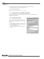
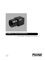
AccuPiXEL Series Camera-Control Software
Installation and Operation Manual
69-0109
Rev. A
Imaging Products
i
Notice Page
Notice
The material contained in this manual consists of information that is proprietary to PULNiX America, Inc., and may only be
used by the purchasers of the product. PULNiX America, Inc. makes no warranty for the use of its product and assumes no
responsibility for any errors which may appear or for damages resulting from the use of the information contained herein.
PULNiX America, Inc. reserves the right to make changes without notice.
Microsoft Windows 2000, Windows 98, Windows 95, Windows NT, and Windows Explorer are either registered trademarks or
trademarks of Microsoft Corporation in the United States and/or other countries.
Warranty
All of our solid-state cameras have a full three-year warranty. If any such product proves defective during this warranty period,
PULNiX America, Inc. will repair the defective product without charge for parts and labor or will provide a replacement in
exchange for the defective product. This warranty shall not apply to any damage, defect or failure caused by improper use or
inadequate maintenance and use.
WARNING
I
S
UL
®
FI
REG
AccuPiXEL Series Camera-Control Software Manual
Printing:August 6, 2002
PULNiX America, Inc.
1330 Orleans Drive
Sunnyvale, CA 94089
Tel:(408) 747-0300
Tel:(800) 445-5444
Fax:(408) 747-0880
E-mail: [email protected]
www.pulnix.com
RM
Changes or modifications to this unit not expressly approved by the party responsible for
FCC compliance could void the user’s authority to operate the equipment.
TE ED
R
PULNiX AMERICA, INC.
REGISTERED TO ISO-9001
FILE #A3942
AccuPiXEL Series Camera-Control Software
ii
Table of Contents
1 Introduction . . . . . . . . . . . . . . . . . . . . . . . . . . . . . . . . . . . . . . . . . .1
1.1 Software Installation. . . . . . . . . . . . . . . . . . . . . . . . . . . . . . . . . . . . . . . . 1
1.1.1
1.1.2
1.1.3
1.1.4
Before Installing the AccuPiXEL Series Camera-Control Software . . . . . . . . .
Installing the Software . . . . . . . . . . . . . . . . . . . . . . . . . . . . . . . . . . . . . . . . . . . .
Installing the Camera Link API DLL (clserXXX.dll) . . . . . . . . . . . . . . . . . . . . .
Uninstalling the Software . . . . . . . . . . . . . . . . . . . . . . . . . . . . . . . . . . . . . . . . . .
1
1
2
2
2 Graphical User Interface . . . . . . . . . . . . . . . . . . . . . . . . . . . . . . . .3
2.1 GUI Features . . . . . . . . . . . . . . . . . . . . . . . . . . . . . . . . . . . . . . . . . . . . . 3
2.2 Open the Link to the Camera . . . . . . . . . . . . . . . . . . . . . . . . . . . . . . . . 3
2.2.1 Open RS-232 Port . . . . . . . . . . . . . . . . . . . . . . . . . . . . . . . . . . . . . . . . . . . . . . . 3
2.2.2 Open Camera Link. . . . . . . . . . . . . . . . . . . . . . . . . . . . . . . . . . . . . . . . . . . . . . . 3
2.3 Operating The Control Software . . . . . . . . . . . . . . . . . . . . . . . . . . . . . 4
2.3.1
2.3.2
2.3.3
2.3.4
2.3.5
Exposure Control . . . . . . . . . . . . . . . . . . . . . . . . . . . . . . . . . . . . . . . . . . . . . . .
Gain Control . . . . . . . . . . . . . . . . . . . . . . . . . . . . . . . . . . . . . . . . . . . . . . . . . . .
Knee Control . . . . . . . . . . . . . . . . . . . . . . . . . . . . . . . . . . . . . . . . . . . . . . . . . . .
“Password” Menu. . . . . . . . . . . . . . . . . . . . . . . . . . . . . . . . . . . . . . . . . . . . . . . .
“Erase EEPROM” Menu . . . . . . . . . . . . . . . . . . . . . . . . . . . . . . . . . . . . . . . . . . .
4
4
5
5
6
3 AccuPiXEL Series Camera Serial Commands. . . . . . . . . . . . . . . .7
AccuPiXEL Series Camera-Control Software
Page iii
Table of Contents
AccuPiXEL Series Camera-Control Software
August 6, 2002
AccuPiXEL Series Camera-Control
Software
PRELIMINARY Operation Manual
TM-1020-15, TM-1020-25, TM-1020-30, and CL versions
TM-1320-15, TM-1320-24, TM-1320-12, and CL versions
TM-2016-8, TM-2016-15, and CL versions
TM-6760 and TM-6760CL
TM-2020-8, TM-2020-15, and CL versions
1
Introduction
The AccuPiXEL series cameras are high resolution, progressive scan cameras with PULNiXproprietary LUT control and other excellent features. The camera control software was developed to
function as standard software for the entire AccuPiXEL series. This software can open either the RS232 serial port (COM) or Camera Link. Camera Link users must physically install the Camera Link
frame grabber board into the PC. They must also install the Camera Link API (clserXXX.dll) software.
These cameras are specially designed to capture images in progressive scan (non-interlace) format,
producing a full frame of electronic shutter images, as well as normal images.
1.1 Software Installation
Following are instructions to install the AccuPiXEL series camera-control software on a PC.
1.1.1 Before Installing the AccuPiXEL Series Camera-Control Software
Before installing the AccuPiXEL series Camera-Control Software, please note the following.
•
The AccuPiXEL series camera-control software requires Microsoft Windows 95, 98, NT 4.0., or
Windows 2000.
•
We recommend that you use small fonts for the Display Properties dialog box in the control panel.
•
The AccuPiXEL series camera-control software requires one free communication port that is not in
conflict with other peripherals such as the mouse or modem.
•
Installation of the AccuPiXEL series camera-control software requires 2.0 MB of free space in
your PC hard disk.
1.1.2 Installing the Software
To install the AccuPiXEL series camera-control software, follow the steps below.
AccuPiXEL Series Camera-Control Software
Page 2
Introduction
1.
2.
3.
Insert the installation diskette into the floppy drive of your PC and run “Setup.exe.”
The installer will direct you to install the application code.
Follow the installer instructions.
Note: You can change the installation directory if you want.
1.1.3 Installing the Camera Link API DLL (clserXXX.dll)
To install the Camera Link control software with frame grabber software, please consult the frame
grabber company or PULNiX.
1.1.4 Uninstalling the Software
You can uninstall the AccuPiXEL series camera-control
software from the control panel. To uninstall, follow the
steps below.
1.
2.
3.
Open “Add/Remove Programs” in the control panel.
Select “TM-1020 Camera Control Station” from the
lists of the installed software.
Click the “Add/Remove” button, then click “Yes” to
confirm.
AccuPiXEL Series Camera-Control Software
Page 3
Graphical User Interface
2
Graphical User Interface
2.1 GUI Features
The following is a list of camera functions that can
be controlled by PC serial commands. The
AccuPiXEL series Camera Link cameras use
differential serial communication through the
Camera Link connector on the rear panel of the
camera.
•
Shutter Mode and Speed
•
Scan Mode (Normal, Binning)
•
Gain
•
LUT (Look-Up Table)
•
Double Knee Control
•
Write / Read settings into / from the EEPROM
2.2 Open the Link to the Camera
For the RS-232 serial port, refer to “Open RS-232
Port”, below. For Camera Link, refer to “Open
Camera Link” below.
2.2.1 Open RS-232 Port
From the main menu tab, select “Comm Port” and
click “Open.” Select the port number, and set 9600
bps, no parity, 8 data bits, 1 stop bit, and click “Done.” Click on the “Report” button and the software
updates the current settings onto the main control panel.
2.2.2 Open Camera Link
Select frame grabber board index. This index is for users who install multiple Camera Link frame
grabbers. For a single board user, the index is selected as zero as default. Once the board index is set,
open Camera Link. Choose the appropriate Camera Link API dll (typically named “clserXXX.dll”)
which is provided by the frame grabber manufacturer. If the board is not installed or the wrong API dll
is selected, an error message appears. If this happens, please contact PULNiX for further assistance.
Click the “Report” button to reflect the current settings onto the main control panel.
AccuPiXEL Series Camera-Control Software
Page 4
Graphical User Interface
2.3 Operating The Control Software
2.3.1 Exposure Control
In Exposure Control, you can specify the shutter mode and scan mode.
2.3.1 (a)
Shutter Mode
In this list box you can select Manual or Asynchronous or Direct
shutter or no shutter mode.
2.3.1 (b)
Shutter Time
The Shutter Time list box allows you to select the specific shutter
speed.
2.3.1 (c)
Scan Mode
The AccuPiXEL series cameras have several selectable scan modes. The Scan Mode list box allows you
to select scan mode (Normal, Binning).
2.3.2 Gain Control
2.3.2 (a)
Gain
The Gain Control box allows you to change the Gain value from 0 to
255 (integer). To change the value, move the slider, or enter the value
directly into the text box.
2.3.2 (b)
V-Top
The V(top) box allows you to change the V(top) value of the A/D
converter from 30% to 85% (integer). To change the value, move the
slider or enter the value directly into the text box.
2.3.2 (c)
V-Bottom
The V(bottom) box allows you to change the V(bottom) value of the A/D converter from 0 to 100%
(integer). To change the value, move the slider or enter the value directly into the text box.
AccuPiXEL Series Camera-Control Software
Page 5
Graphical User Interface
2.3.3 Knee Control
The Knee Control box allows you to set your own knee
value to each LUT. For more detail regarding knee control,
please refer to the appropriate hardware operation manual or
datasheet.
2.3.3 (a)
LUT (Look-Up Table) Selection
The LUT Selection box allows you to select the linear, knee,
or gamma 0.45 output.
2.3.3 (b)
Knee Selection
The Knee Selection box allows you to select the preset knee
control LUT. The AccuPiXEL series cameras have 8 preset
knee control LUTs.
2.3.3 (c)
Knee Control
The Knee Control graphical control allows you to change two knee point values visually by clicking
and dragging the “knee line.” You may enter X1, Y1, X2, Y2 values directly to adjust the knee curve.
When you have chosen the value you want and are ready to set this value to the camera, click the “Send
Knees” button.
2.3.4 “Password” Menu
2.3.4 (a)
Password
Please contact PULNiX for password access. The password allows
access to the EEPROM to rewrite or erase factory settings.
AccuPiXEL Series Camera-Control Software
Page 6
Graphical User Interface
2.3.5 “Erase EEPROM” Menu
2.3.5 (a)
Load Setting From the EEPROM
The EEPROM section consists of three memory locations that
allow you to Load (open), Write (save) and Report the current
configuration.
“Page Memory” has seven pages available to write current
configurations. Page “0” is the factory default configuration and
cannot be edited without a password. Page memory “1” is power
up default. This page will allow you to save your default
configuration to load at power up. Page memory will allow you to save the current Exposure Control,
Knee, Gain, Vtop, and Vbtm settings.
“User Memory” will allow you to load, write, and report the current configuration for Gain, Vtop, and
Vbtm only.
“System Memory” is the same as “User Memory” except that it requires a password for access. “Current
Memory” is the camera’s current configuration. Select “Current” and click the “Report” button to
display the cameras settings.
The “Load” option in the menu bar allows you to restore the Gain Table setting from EEPROM. Click
on “Load” and select “From Gain Table” in the menu to restore the setting from four user memory pages
and four preset setting memory pages.
AccuPiXEL Series Camera-Control Software
Page 7
AccuPiXEL Series Camera Serial Commands
3
AccuPiXEL Series Camera Serial Commands
The AccuPiXEL series cameras can be controlled by serial command either via RS-232 or Camera
Link. The Start character is always “:” and the End character is always <CR> (return). For example, to
set Asynchronous Pulse Width Mode, send the command :SA9<CR> to the camera. The following table
contains serial commands that can be used to control the camera.
TABLE 1.
1
Serial Command List
First
Character
Second
Character
Third
Character
“S” (Shutter)
“M” (Manual)
“0” - “9”
Mode
ACK
Manual Shutter Mode
“A” (ASYNC)
“0” - “8”
Mode
ACK
Async Shutter Mode
“9” (Pulse
Width Mode)
ACK
Async Pulse Width Mode
“X”
“000” - “419”
ACK
Direct Shutter Mode
Response
Functions
2
“G” (Gain)
“M”
“00” - “FF”
ACK
Gain Control
3
“V” (A/D Vref)
“T” (Top)
“00” - “FF”
ACK
Vtop reference setting
“B” (Bottom)
“00” - “FF”
ACK
Vbtm reference setting
“P” (Page)
“0” - “6”
ACK
Write current setting to Page
EEPROM
“U” (User)
“A” - “D”
ACK
Write current setting to User
EEPROM
“S” (System)
“A” - “D”
ACK
Write current setting to System
EEPROM
“P” (Page)
“0” - “6”
ACK
Restore setting from Page
EEPROM
“U” (User)
“A” - “D”
ACK
Restore setting from User
EEPROM
“S” (System)
“A” - “D”
ACK
Restore setting from System
EEPROM
“N” (kNee)
“0” - “9”
ACK
Load Preset Knee Table
“P” (Page)
“0” - “6”
ACK
ACK + “P” + (“9” - “F”) + 16
bytes
“U” (User)
“A” - “D”
ACK
ACK + “U” + (“A” - “D”) + 6
bytes
“S” (System)
“A” - “D”
ACK
ACK + “S” + (“A” - “D”) + (6
bytes)
“R” (Current)
ACK
ACK + “RR” + 16 bytes
“X” (Execute)
ACK
Set Camera with loaded data
“D” (Date)
info
Report CPU program version
4
5
6
“W” (Write)
“L”
“R” (Report)
AccuPiXEL Series Camera-Control Software
Page 8
AccuPiXEL Series Camera Serial Commands
TABLE 1.
7
Serial Command List (Continued)
First
Character
Second
Character
Third
Character
“T” (Table)
“N” (kNee)
X1 + Y1 + X2
+ Y2
Response
ACK
Functions
(X1, Y1) coordinate for knee 1
X1, Y1, X2, Y2: “00 - FF”
(X2, Y2) coordinate for knee 2
“M” (Gamma)
ACK
“L” (Linear)
ACK
“C” (Switch A,
B Table)
8
“N”
ACK
“0” (Normal)
ACK
Normal Scan Formal
“3” (Binning)
ACK
Double Speed Binning
Note:
One byte of data consists of two ASCII codes. For example, 0x3A is “3” (0 x 33) and “A”
(0 x 41). <ACK> is 0 x 06. <NAK> is 0 x 15. <CR> is 0 x 0D.
Note:
1-byte data is represented in 2 ASCII characters, e.g. 0x3A is “3A” or 0x3341.
<CR> = 0x0D
<ACK> = 0x06
<NAK> = 0x15
RS Command:
RS Return:
TABLE 2.
“0” or “1”
Command or response terminator
Command accepted
Command not accepted
RR<CR>
RR + “16 bytes” + <CR>
16 Bytes Status Report
Byte 1
MGCL (1 byte)
--
CDS Gain
Byte 2
Vtop(1 byte)
--
A/D reference voltage Top
Byte 3
Vbtm(1 byte)
--
A/D reference voltage Bottom
Byte 4
XA1 (1 byte)
--
X-Coordinate of right knee for table A
Byte 5
YA1 (1 byte)
--
Y-Coordinate of right knee for table A
Byte 6
XA2 (1 byte)
--
X-Coordinate of right knee for table A
Byte 7
YA2 (1 byte)
--
Y-Coordinate of right knee for table A
Byte 8
XB1
--
X-Coordinate of left knee for table B
Byte 9
YB1
--
Y-Coordinate of left knee for table B
Byte 10
XB2
--
X-Coordinate of left knee for table B
Byte 11
YB2
--
Y-Coordinate of left knee for table B
AccuPiXEL Series Camera-Control Software
Page 9
AccuPiXEL Series Camera Serial Commands
TABLE 2.
TABLE 3.
16 Bytes Status Report (Continued)
Byte 12
FUNCFLAG1 (1 byte)
--
function flag #1
Byte 13
FUNCFLAG2 (1 byte)
--
function flag #2
Byte 14
SHTRNUM (1 byte)
--
current shutter number
Byte 15, 16
SHTRVAL (2 byte)
--
manual/direct shutter value
Function Flag Description 1
BIT
7
6
5
4
3
2
1
0
FUNCFLAG #1
Resv
Resv
Resv
Resv
SHTR2FLG
SHTR1FLG
MSEL2FLG
MSEL1FLG
SHTR2FLG (Bit3) -- 00 - (0) no shutter, 01 - (1) normal shutter
SHTR1FLG (Bit2) -- 10 - (2) direct shutter, 11- (3) async shutter
MSEL2FLG (Bit1) -- 00 - (0) normal scan, 01 - (1) partial scan #1 (optional)
MSEL1FLG (Bit0) -- 10 - (0) normal scan, #2 (optional), 11-(3) two-row scan
TABLE 4.
Function Flag Description 2
BIT
FUNCFLAG #2
7
6
5
4
3
2
1
0
TSELFLG
LUTB2FLG
LUTB1FLG
LUTA2FLG
LUTA1FLG
TSELFLG (Bit4) -- 0 - Select table A, 1 - Select table B
LUTB2FLG (Bit3) -- 00 - Linear mode; 01 - Knee mode (for table B)
LUTB1FLG (Bit2) --10 - Gamma mode; 11 - Direct input mode (reserved)
LUTA2FLG (Bit1) -- 00 - Linear mode; 01 - Knee mode (for table A)
LUTA1FLG (Bit0) -- 10 - Gamma mode; 11 - Direct input mode (reserved)
AccuPiXEL Series Camera-Control Software
Imaging Products
JAI PULNiX, Inc.
1330 Orleans Drive
Sunnyvale, CA 94089
Tel: 408-747-0300
Tel: 800-445-5444
Fax: 408-747-0660
Email: [email protected]
w w w . j a i p u l n i x . c o m
69-0109
Rev. A