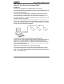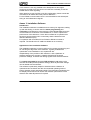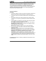
1
PRO 18 Series
Installation Manual
May 2007
Part 201362.05
PRO 18 Series Installation Manual
Disclaimer
The contents of this document are provided on an "as is" basis. No representation or warranty (either
express or implied) is made as to the completeness, accuracy or reliability of the contents of this document.
The manufacturer reserves the right to change designs or specifications without obligation and without
further notice. Except as otherwise provided, all warranties, express or implied, including without limitation
any implied warranties of merchantability and fitness for a particular purpose are expressly excluded.
Intellectual Property and Copyright
The contents of this document are provided on an "as is" basis. No representation or warranty (either
express or implied) is made as to the completeness, accuracy or reliability of the contents of this document.
The manufacturer reserves the right to change designs or specifications without obligation and without
further notice. Except as otherwise provided, all warranties, express or implied, including without limitation
any implied warranties of merchantability and fitness for a particular purpose are expressly excluded.
General Warning
This product must only be installed, configured and used strictly in accordance with the General Terms and
Conditions, User Manual and product documents available from Xtralis. All proper health and safety
precautions must be taken during the installation, commissioning and maintenance of the product. The
system should not be connected to a power source until all the components have been installed. Proper
safety precautions must be taken during tests and maintenance of the products when these are still
connected to the power source. Failure to do so or tampering with the electronics inside the products can
result in an electric shock causing injury or death and may cause equipment damage. Xtralis is not
responsible and cannot be held accountable for any liability that may arise due to improper use of the
equipment and/or failure to take proper precautions. Only persons trained through an Xtralis accredited
training course can install, test and maintain the system.
Liability
You agree to install, configure and use the products strictly in accordance with the User Manual and product
documents available from Xtralis.
Xtralis is not liable to you or any other person for incidental, indirect, or consequential loss, expense or
damages of any kind including without limitation, loss of business, loss of profits or loss of data arising out
of your use of the products. Without limiting this general disclaimer the following specific warnings and
disclaimers also apply:
Fitness for Purpose
You agree that you have been provided with a reasonable opportunity to appraise the products and have
made your own independent assessment of the fitness or suitability of the products for your purpose. You
acknowledge that you have not relied on any oral or written information, representation or advice given by
or on behalf of Xtralis or its representatives.
Total Liability
To the fullest extent permitted by law that any limitation or exclusion cannot apply, the total liability of Xtralis
in relation to the products is limited to:
(i) in the case of services, the cost of having the services supplied again; or
(ii) in the case of goods, the lowest cost of replacing the goods, acquiring equivalent goods or having the
goods repaired.
Indemnification
You agree to fully indemnify and hold Xtralis harmless for any claim, cost, demand or damage (including
legal costs on a full indemnity basis) incurred or which may be incurred arising from your use of the
products.
Miscellaneous
If any provision outlined above is found to be invalid or unenforceable by a court of law, such invalidity or
unenforceability will not affect the remainder which will continue in full force and effect. All rights not
expressly granted are reserved.
Doc 10650_05
i
PRO 18 Series Installation Manual
Document Conventions
The following typographic conventions are used in this document.
Convention
Bold
Italics
Description
Used to denote: emphasis
Used for names of menus, menu options, toolbar buttons
Used to denote: references to other parts of this document or other documents.
Used for the result of an action
The following icons are used in this document
Convention
Description
Caution: This icon is used to indicate that there is a danger to equipment. The
danger could be loss of data, physical damage, or permanent corruption of
configuration details.
Warning: This icon is used to indicate that there is a danger of electric shock.
This may lead to death or permanent injury.
Warning: This icon is used to indicate that there is a danger of inhaling
dangerous substances. This may lead to death or permanent injury.
Tradename statement
ADPRO is a registered trademark of Xtralis AG Pty Ltd.
Lightning or Related Voltage Surges
Equipment malfunction caused by lightning or related voltage surges is specifically exempted from the
warranty conditions.
Xtralis AG Pty Ltd reserves the right as to final determination of whether or not an equipment malfunction
was caused by lightning or related voltage surges.
Contact Us
The Americas +1 781 740 2223 Asia +852 2297 2438 Australia and New Zealand +61 3 9936 7000
Continental Europe +41 55 285 99 99 UK and the Middle East +44 1442 242 330
www.xtralis.com/adpro
Doc 10650_05
PRO 18 Series Installation Manual
Overview
This manual describes the PRO 18 series of detectors, which includes the
following models:
•
PRO 18
•
PRO 18H
•
PRO 18W
•
PRO 18WH
The PRO 18 series of detectors are highly sensitive passive infrared
detectors with wide angle, volumetric differential fields of view, designed for
detection outdoors. They incorporate microprocessor controlled signal
processing, including signal shape analysis, adaptive threshold level by
feedback of environmental effects, temperature compensation and rejection
of disturbance signals.
Sensitivity adjustments are done with DIP switches for each individual unit,
to alter the required detection range in order to adapt to the specific needs
of an installation.
In addition to the hardware settings, adjustments can be made in a two way
communication mode and signals displayed on a PC screen by using the
optional installation software and RS485 communication interface module.
Doc 10650_05
PRO 18 Series Installation Manual
Contents
1.0
Mounting and Installation.......................................................................... 1
2.0
Hardware / Software Mode of Operation ................................................. 1
3.0
Connecting the PRO 18 .............................................................................. 2
3.1 Alarm Signalling ..................................................................... 2
3.2 Cover Tamper Switch............................................................. 2
3.3 Electronics Supply ................................................................. 2
3.4 Anti-Tamper Output ............................................................... 2
4.0
Field of View................................................................................................ 3
4.1 PRO 18..................................................................................... 3
4.2 PRO 18H .................................................................................. 3
4.3 PRO 18W ................................................................................. 3
4.4 PRO 18WH............................................................................... 3
5.0
Alignment..................................................................................................... 3
5.1 Typical Vertical Alignment .................................................... 4
5.1.1 PRO 18 for a required detection range of 24 m............. 4
5.1.2 PRO 18H for a required detection range of 30 m .......... 4
5.1.3 PRO 18W for a required detection range of 21 m ......... 5
5.1.4 PRO 18WH for a required detection range of 27 m....... 5
5.2 Typical Horizontal Alignment................................................ 6
5.2.1 PRO 18 .......................................................................... 6
5.2.2 PRO 18H........................................................................ 6
5.2.3 PRO 18W ....................................................................... 7
5.2.4 PRO 18WH .................................................................... 8
6.0
Sensitivity Settings ...................................................................................... 9
7.0
Adaptive Threshold Discrimination (ATD) .............................................. 9
8.0
Pulse Count................................................................................................ 10
9.0
Test ............................................................................................................. 11
10.0
Anti Tamper Feature ................................................................................ 11
11.0
LED ............................................................................................................ 12
12.0
Alarm Management .................................................................................. 13
13.0
Alarm Time................................................................................................ 13
14.0
Internal Temperature Compensation...................................................... 13
Doc 10650_05
i
PRO 18 Series Installation Manual
15.0
Internal Heater (PRO 18H and PRO 18WH only)................................. 13
16.0
External Sensitivity Adjustment via RS485 Data Bus ........................... 14
17.0
Signal Processing....................................................................................... 14
18.0
Accessories ................................................................................................. 14
18.1 Interface Module IF 485B and Installation Software ......... 14
18.2 Cordless Walk Tester CT 45................................................ 16
18.2.1 Receiver ....................................................................... 16
18.2.2 Transmitter ................................................................... 17
18.3 Pole Mount Hardware ZA P-L1............................................ 17
19.0
Maintenance .............................................................................................. 18
20.0
General Comment on the PRO 18 ........................................................... 18
21.0
Wiring the Alarm Outputs ....................................................................... 20
22.0
Specifications ............................................................................................. 21
22.1 Mechanical Dimensions ...................................................... 23
Annex 1: Electronic Board and Terminal Block ............................................... 24
Annex 2: Two Way Communication RS485....................................................... 26
Annex 3: Installation Software............................................................................ 27
Doc 10650_05
PRO 18 Series Installation Manual
1.0
Mounting and Installation
The mounting structure should be stiff enough and resistant to significant
deflections in windy conditions. Movement of the PRO 18 caused by
vibrations or other movements will result in swings of the field of view
covered by the PRO 18 and could cause disturbance signals. These
unwanted signals may lead to an increase of the alarm threshold level,
which reduces the detection probability, or in certain cases can lead to
unwanted alarms.
The PRO 18 is supplied with a bracket suitable for wall mounting. A
separate attachment (ZA P-L1) is available for mounting the detector on a
pole, refer to section 18.3.
CAUTION: It is very important that the cover of the PRO 18 is
securely tightened. It must be tightened with the two
screws to the point where it cannot be closed further
with reasonable force. There will then be hardly any gap
between the cover and the bottom part of the housing
(considerably less than 1 mm).
The cable entry assembly should not be changed without authorisation
by the manufacturer. It is specifically designed to allow air entry and exit so
that the inside of the PRO 18 is always at atmospheric pressure. This
prevents moisture being sucked into the PRO 18 by a drop in internal
pressure, likely to happen when rainfall rapidly cools down a unit warmed
up in the sun.
The nut on the cable entry assembly should be tightened to clamp the
cable in place with the nylon grip. If the cable diameter is too small to be
held by the grip, insulation tape should be wound around the cable to
increase the outside diameter to a suitable size.
2.0
Hardware / Software Mode of Operation
The PRO detectors can be operated in two modes of operation:
•
Hardware mode: The configuration and operation is managed by
DIP switches on the PRO detectors. This particularly applies to the
Sensitivity Settings. Note that some configuration changes can only
be made through the installation software.
Doc 10650_05
1
PRO 18 Series Installation Manual
•
3.0
Software mode: Through the installation software and an RS485
connection, the configuration and operation is managed through
software settings. This can be done proactively, or setup using the
software and then disconnected from the RS485 bus. The detectors
store their configuration locally.
Connecting the PRO 18
For the definition of the connector board and terminal block refer to Annex
1: Electronic Board and Terminal Block for details.
3.1
Alarm Signalling
There are two types of alarm signalling from the PRO 18:
•
one SPST potential-free relay contact
•
an RS485 two way communication link (refer to Annex 2: Two Way
Communication RS 485)
With the factory default setting, the relay contact opens on alarm. The
output logic and function can be changed using the installation software.
During turn-on time, the relay output is in the alarm state.
3.2
Cover Tamper Switch
To detect attempts to open the PRO 18, a tamper switch is fitted on the
cover. Its contact opens when the cover is opened and it should be
connected in series with the normally closed relay contact.
3.3
Electronics Supply
The PRO 18 can operate on either a 10.5 – 30 VDC or 24 VAC supply. If
using a DC supply, ensure that polarity is correct when connecting power to
the electronic circuit. Protective circuitry will withstand a short period of
reversed polarity, but damage will result if this is not corrected quickly.
3.4
Anti-Tamper Output
To detect if the PRO 18 has been moved, a movement detection sensor is
located in the unit. If the PRO 18 is moved, the open collector transistor will
signal. The transistor is open circuit in its default non-tamper state.
Doc 10650_05
2
PRO 18 Series Installation Manual
4.0
4.1
Field of View
PRO 18
The PRO 18 has a volumetric 50° angle of detection, with differential
detection areas and a nominal range of 24 m.
4.2
PRO 18H
The PRO 18H has a volumetric 50° angle of detection, with differential
detection areas and a nominal range of 30 m.
4.3
PRO 18W
The PRO 18W has a volumetric 90° angle of detection, with differential
detection areas and a nominal range of 21 m.
4.4
PRO 18WH
The PRO 18WH has a volumetric 90° angle of detection, with differential
detection areas and a nominal range of 27 m.
5.0
Alignment
The detection range of a PIR detector is not limited but a function of size,
speed and temperature contrast of a target against its background. The
PRO 18 should be aligned so that a natural or artificial background at the
end of the range terminates the field of view.
Vertical alignment is optimal when the upper edge of the field of view is at
1.5 to 2.5 m above ground at the end of the required detection range,
provided that the field of view is properly terminated.
Alignment can be done visually by looking along the groove on the top of
the detector. This line of sight corresponds to the upper edge and centre of
the detection pattern.
Where the detection range has to be limited, a terminating screen can be
used to avoid detection of targets beyond the wanted range.
Note: Adverse environmental conditions may reduce the maximum
detection range.
Doc 10650_05
3
PRO 18 Series Installation Manual
5.1
Typical Vertical Alignment
5.1.1
PRO 18 for a required detection range of 24 m
The PRO 18 should be aligned vertically so that at least the lower half of a
person standing upright at the maximum required range will be within the
field of view (refer to Figure 1 - Side view of PRO 18 below).
4m
3m
2m
1.5 m
1m
0 1
24 m
Figure 1 - Side view of PRO 18
5.1.2
PRO 18H for a required detection range of 30 m
The PRO 18H should be aligned vertically so that at least the lower half of
a person standing upright at the maximum required range will be within the
field of view (refer to Figure 2 - Side view of PRO 18H below).
4m
3m
2m
1.5 m
1m
0 1
30 m
Figure 2 - Side view of PRO 18H
Doc 10650_05
4
PRO 18 Series Installation Manual
5.1.3
PRO 18W for a required detection range of 21 m
The PRO 18W should be aligned vertically so that at least the lower half of
a person standing upright at the maximum required range will be within the
field of view (refer to Figure 3 - Side view of PRO 18W below).
Figure 3 - Side view of PRO 18W
5.1.4
PRO 18WH for a required detection range of 27 m
The PRO 18WH should be aligned vertically so that at least the lower half
of a person standing upright at the maximum required range will be within
the field of view (refer to Figure 4 - Side view of PRO 18WH below).
Figure 4 - Side view of PRO 18WH
Doc 10650_05
5
PRO 18 Series Installation Manual
5.2
5.2.1
Typical Horizontal Alignment
PRO 18
Horizontal alignment should be done to avoid unwanted signals being
generated by targets (branches, bushes, fences) likely to be moved by
wind (refer to Figure 5 - Top view of PRO 18 below). Movement within the
field of view will reduce the sensitivity of the PRO 18 by increasing the
alarm threshold level and may lead to unwanted alarms.
10 m
5m
50o
0
5m
10 m
0
5m
10 m
15 m
20 m
25 m
Figure 5 - Top view of PRO 18
5.2.2
PRO 18H
Horizontal alignment should be done to avoid unwanted signals being
generated by targets (branches, bushes, fences) likely to be moved by
wind (refer to Figure 6 - Top view of PRO 18H below). Movement within the
field of view will reduce the sensitivity of the PRO 18H by increasing the
alarm threshold level and may lead to unwanted alarms.
Doc 10650_05
6
PRO 18 Series Installation Manual
10 m
5m
50o
0
5m
10 m
0
5m
10 m
15 m
20 m
25 m
30 m
Figure 6 - Top view of PRO 18H
5.2.3
PRO 18W
Horizontal alignment should be done to avoid unwanted signals being
generated by targets (branches, bushes, fences) likely to be moved by
wind (refer to Figure 7 - Top view of PRO 18W below). Movement within
the field of view will reduce the sensitivity of the PRO 18W by increasing
the alarm threshold level and may lead to unwanted alarms.
Figure 7 - Top view of PRO 18W
Doc 10650_05
7
PRO 18 Series Installation Manual
5.2.4
PRO 18WH
Horizontal alignment should be done to avoid unwanted signals being
generated by targets (branches, bushes, fences) likely to be moved by
wind (refer to Figure 8 - Top view of PRO 18WH below). Movement within
the field of view will reduce the sensitivity of the PRO 18WH by increasing
the alarm threshold level and may lead to unwanted alarms.
Figure 8 - Top view of PRO 18WH
Note: The detection patterns of Figures 1 to 8 are for illustration of the
volumetric coverage of the detectors. Actual detection zones depend
on the mounting height and exact alignment.
CAUTION: When walk testing the unit, the threshold level will
increase as a result of the signal generated by the
target and decrease exponentially in time after the
event. To make sure that original sensitivity is reached,
wait at least for three minutes between each crossing or
disable the Adaptive Threshold Discrimination (ATD)
function by setting DIP switch 3 to “off”.
Doc 10650_05
8
PRO 18 Series Installation Manual
If the Installation software is used for monitored walk tests and DIP
switches 1 and 2 are set to software settings (on – on), the threshold level
can be kept to its nominal value by changing the configuration of the ATD
for this test.
6.0
Sensitivity Settings
The various settings of the PRO 18 are made by means of multiple DIP
switches on the connector board.
The DIP switches 1 and 2 are for sensitivity setting, depending on the
required detection performance. If the maximum required range is less than
the nominal range of the detector, it is recommended to reduce the overall
sensitivity to reduce nuisance alarms.
(*)
Switch 1 and 2
Overall Sensitivity
off – off
40%
off – on
75%
on – off
100% (*)
on – on
Software Settings
20% … 140% (**)
Factory Setting.
(**) With DIP switches 1 and 2 both set to “on”, the overall sensitivity is
100% factory setting but can be changed with the installation software.
If the sensitivity is adjusted with the installation software, the
programmed value will remain active following a power off.
Operation of the PRO 18 with overall sensitivity set to more than 100%
is not recommended in outdoor applications as the nuisance alarm
rate could increase significantly.
7.0
Adaptive Threshold Discrimination (ATD)
The background noise is constantly averaged and used to adjust the
threshold levels for the alarm. This special feature reduces the probability
of nuisance alarms caused by wind, moving vegetation or objects that have
a thermal contrast, although usually weaker than that of a person.
Doc 10650_05
9
PRO 18 Series Installation Manual
Each signal exceeding a certain minimum value will activate the ATD and
increase the threshold levels, depending on its strength. The time
constants for increase and decrease are chosen in a way to adapt to
gradual changes. Signals generated by a person moving within the
specified speed range, however, are fast enough for detection.
Repeated movement of any kind within the field of view is therefore
activating the ATD, reducing the overall sensitivity. This has to be noted
particularly when walk testing the PRO 18 following installation.
DIP switch 3 is used to activate or deactivate the ATD.
(*)
Switch 3
ATD
off
off (*)
on
on (**)
Operation of the PRO 18 in this mode is possible but not
recommended in outdoor applications, as the nuisance alarm rate
could increase significantly as a result of turbulence.
(**) Factory Setting.
Note: When walk testing the unit, the threshold level will increase as a
result of the signal generated by the target and decrease exponentially in
time after the event. To make sure that original sensitivity is reached, wait
for at least three minutes between each crossing or disable the ATD
function by setting DIP switch 3 to “off“.
If the Installation software is used for monitored walk tests and DIP
switches 1 and 2 are set to software settings (on – on), the threshold level
can be kept to its nominal value by changing the configuration of the ATD
to “off“ for this test.
8.0
Pulse Count
DIP switch 4 is used to set a pulse count delay for the alarm activation.
This means that the alarm output is only activated after a pre-set number of
pulses having reached the alarm criteria within a certain period of time. If
DIP switch 4 is set to “on” the pulse count delay is 3.
The programmed setting adds the defined number of pulses to the one
pulse required without pulse count (e.g. pulse count 3 results in 1 + 3 = 4
pulses for alarm).
Doc 10650_05
10
PRO 18 Series Installation Manual
If software settings are used (DIP switches 1 and 2 need both to be set
to “on”) the pulse count delay can be programmed to any value between
0 - 10.
(*)
Switch 4
Pulse Count
off
off
on
on (*)
Factory Setting 3.
9.0
Test
When doing a walk test using the CT 45 (refer to section 18.2), in HW
mode DIP switch 5 must be set to “on“ or when operating the detector in
SW mode the “test” mode must be set to “on“. After the walk test the “test”
mode must be switched “off“.
Important: The transmitter CT 45-T of the cordless installation tester has to
be placed within the housing with the detector cover closed and securely
tightened. The antenna of the transmitter must be placed straight in the
detector housing.
(*)
Switch 5
Test
off
off (*)
on
on
Factory Setting.
10.0
Anti Tamper Feature
The PRO 18 is equipped with sophisticated protection against tampering. It
detects misalignment of a detector from its original position, defined during
installation and commissioning.
A change of the detector position generates a permanent alarm until the
detector’s alignment is back in its original position or until the position has
purposely been reset. When using the alarm management with RS485
communication a tamper alarm will be identified separately.
The transistor and/or relay may be configured via software to activate. By
default, the transistor only activates for a tamper.
After the turn-on time of typically 60 seconds from power on, the detector
determines and stores its alignment position (only with the detector cover
closed).
Doc 10650_05
11
PRO 18 Series Installation Manual
After opening and closing the cover with the unit powered on, the detector
determines its alignment position and stores the position value after five
minutes again without having the detector in permanent alarm state. During
this time the anti tamper sensor can be reset with a power off-on. When
using the PRO software the anti tamper sensor can be reset by means of
setting the tamper reset function in the setting window.
During normal operation, resetting the anti tamper sensor after the
detector’s position has been changed, can be done either remotely with the
PRO program (takes app. 10 seconds) or a power off-on (60 seconds).
Hardware Mode
When operating the detector in the HW mode, the anti vandal function is
activated by setting DIP switch 6 to “on“.
(*)
Switch 6
Anti Tamper Feature
off
off
on
on (*)
Factory Setting.
Software Mode
Operating the detector in the SW mode, the anti tamper function is
activated by means of setting of the corresponding parameter in the
settings of the PRO programs to “on“. By default, the anti-tamper function
is enabled.
11.0
LED
The electronic board is fitted with a dual LED, which has a red and green
colour side. This can be monitored during installation while the cover is
open.
•
•
The red LED indicates whether the detector is in alarm state
The green LED flashing at 2 Hz frequency indicates the detector
ready state.
During the turn-on time, the red LED is on.
Doc 10650_05
12
PRO 18 Series Installation Manual
12.0
Alarm Management
The PRO 18 features an alarm management function over RS485
communication. All the detectors connected to the same data bus provide
all the information relevant to an alarm in a two-byte string. For further
information please contact the manufacturer.
13.0
Alarm Time
Alarm time and count per event is determined by the duration of the
detected event and depends on the shape and amplitude of the alarm
signal. Individual alarm pulses have a minimum time of approximately
2.5 s.
14.0
Internal Temperature Compensation
The PRO 18 is detecting radiation differences of a target against its
background. In the course of the day and year the contrast of a person will
vary considerably and affect the signal strength. To compensate for this
contrast variation, the PRO 18 has internal temperature compensation with
maximum sensitivity at approximately 30°C (where the contrast of a human
target is weakest) and gradual reduction at higher and lower temperatures.
CAUTION: When installing a unit the internal temperature may take
up to 30 minutes or more to stabilise to the actual
external temperature. Sufficient time should be given to
the PRO 18 to reach the correct internal temperature
and sensitivity before performing walk tests.
During the initial period of operation it is strongly recommended that walk
tests are repeated and signals monitored under various weather conditions,
such as high and low temperatures, wind, fog, snow, rain etc. to obtain
comparative data and information on the effects of environmental
conditions on detection and nuisance alarm probabilities for this particular
site. Fine-tuning of the detector based on this data, by changing the
sensitivity settings, may optimise the performance.
15.0
Internal Heater (PRO 18H and PRO 18WH only)
A regulated heater connected to the electronic board and powered by the
supply voltage of the PRO 18H and PRO 18WH prevents the optical
surfaces from fogging or frosting and maintains the internal temperature at
optimal levels.
Doc 10650_05
13
PRO 18 Series Installation Manual
16.0
External Sensitivity Adjustment via RS485 Data Bus
If DIP switches 1 and 2 are both set to “on”, the detection performance
can be adjusted via the RS485 two way communication port. Overall
sensitivity of the PRO 18 can be set to any value between 20% and 140%.
The external sensitivity adjustment may also be used if overall sensitivity
has to be changed at certain periods of the day or year depending on the
prevailing thermal contrasts. Field tests in the actual environment will
determine the optimum settings.
17.0
Signal Processing
The sophisticated signal processing ensures optimum performance and
reliability of the detector.
The background noise is sampled and averaged over a large number of
cycles, giving a noise dependent value for the alarm threshold and to start
the adaptive signal shape analysis whenever a certain amplitude value is
exceeded.
If the threshold has temporarily been increased by high background noise
or repeated movements in the field of view, the exponential decay of the
threshold level to its original value will take approximately 1… 2 minutes
from the end of the event.
Once the threshold level value has been exceeded, the microprocessor
starts its signal shape analysis routine where a number of interdependent
parameters are calculated and analysed.
Only if a signal meets all the predetermined criteria an alarm will be
generated.
18.0
Accessories
18.1 Interface Module IF 485B and Installation Software
The installation software is very useful for alignment and signal check
during setting up and routine maintenance. It will indicate the amplitudes
generated by wanted as well as unwanted targets and help setting the gain
control correctly during walk tests and also show the magnitude of
disturbance signals. The installation software is to be installed on a PC; an
interface module is required to convert RS232 to RS485. The information
for installation and signal monitoring is displayed on the screen of the PC.
Doc 10650_05
14
PRO 18 Series Installation Manual
If more than one detector is connected to the same RS485 communication
bus, each detector must have a different identification number.
The RS485 standard requires a bus topology. To ensure proper
communication, the data must be terminated on both ends. The IF 485B
features a built-in termination resistor.
The interface module IF 485B is available as an accessory and is preconfigured and equipped with the necessary connectors to be operated
with any detector of the PRO Series.
The input cable is 5.0 m long and is terminated with a RJ12 connector
fitting into the test socket on the electronic board of the detector.
The connection to the PC’s COM port is with a standard 3.0 m RS232 or
with a 1.8 m USB cable (supplied with the IF 485B).
Doc 10650_05
15
PRO 18 Series Installation Manual
18.2 Cordless Walk Tester CT 45
The cordless walk tester, CT 45, is an accessory for checking the detector
alignment remotely. During a walk test it indicates a detector alarm with a
beeper and an LED. The walk tester CT 45 consists of a transmitter (CT
45-T) and a receiver (CT 45-R).
18.2.1 Receiver
LED Description
•
•
•
Power: LED indicates power is on and battery o.k., dims when
voltage is low.
Comm.: LED indicates communication with transmitter is ok.
Alarm: LED lights up as long as alarm is activated.
Doc 10650_05
16
PRO 18 Series Installation Manual
18.2.2 Transmitter
Description
1. Power and Communication plug: Connects to the detector’s test
socket
2. Power LED: LED indicates correct connection and power.
3. Antenna: To be placed straight in the detector housing
18.3 Pole Mount Hardware ZA P-L1
Pole mounting bracket with two strap bands for poles 4 – 16 cm in
diameter.
Doc 10650_05
17
PRO 18 Series Installation Manual
19.0
Maintenance
The detector has been designed to be virtually maintenance free but the
following precautions are recommended:
1.
Visual inspection of the front window for accumulation of dirt on the
outer surface or damage at intervals of approximately 6 months. Clean
the surface with a paper tissue and avoid rubbing dirt into the surface.
Use the same precautions as for a camera lens.
2.
Visual inspection of the inside for ingress of water is recommended
at intervals of 6 to 12 months or whenever the unit is opened for
adjustments or tests. Make sure that the sealing gasket is in place
before closing the cover tightly again.
3.
Inspection is recommended following extreme conditions such as
snow storms, sand storms, hail etc. to make sure that nothing has
been damaged and the sensitivity is not reduced by accumulation of
snow, sand or dirt on the front window. Snow or dust in front of the
window should be removed by hand or by using a soft instrument (e.g.
a cloth covered wooden stick).
20.0
General Comment on the PRO 18
•
Despite the advanced design and state-of-the-art features of the PRO
18 it is in the nature of a Passive Infrared Detector that an absolute
detection probability and freedom from nuisance alarms cannot be
achieved, masking of the PRO 18 cannot be excluded.
•
Detection is a function of thermal contrast, speed and size of a target
crossing the field of view. Contrast conditions can vary significantly in
the course of the day and year.
•
Detection depends also on the sensitivity settings, the exact aiming and
the prevailing weather conditions, as well as the nature of the target
and background.
•
The detection pattern and frequency response of the PRO 18 has been
optimised for the detection of human size targets crossing the field of
view in an upright position at speeds in the range of 0.2 - 5.0 m/s.
•
Detection of slow moving targets at long range may become uncertain
under weak contrast conditions. It is strongly recommended to limit the
zone length to less than the nominal range when human targets
moving at the minimum specified speed need to be detected with high
probability.
Doc 10650_05
18
PRO 18 Series Installation Manual
•
Animals or crawling people may or may not be detected depending on
their size, speed, contrast and distance from the PRO 18.
•
It is therefore strongly recommended to combine the PRO 18 with an
alarm verification such as CCTV or a second system using other
physical means of detection (e.g. VMD).
•
Any liability for direct or indirect damage resulting from the use of the
PRO 18 as a detection device is explicitly disclaimed.
•
The information in this product manual is based on testing of samples
taken at random from production and believed to be representative,
E&OE.
Doc 10650_05
19
PRO 18 Series Installation Manual
21.0
Wiring the Alarm Outputs
If used with a product that supports tamper detecting inputs, the PRO
detector can be connected to signal both cover tamper and alignment
tamper.
The product (eg FastTrace) should have the alarm input configured as
Dual-End-of-Line Normally Closed. The PRO detector should be wired as
below:
Doc 10650_05
20
PRO 18 Series Installation Manual
22.0
Specifications
Model
Optical
Nominal Range
Width @ Nominal Range
Mounting Height
Detection Speed
Sensor
Spectral Response
Optics
Front Window
Sensitivity Adjustment
Mechanical
Case Material
Colour
Weight
Cable Feeds
Outer Cable Diameter
Electrical
Supply Voltage
Current Consumption
Alarm Relay Output
Transistor Output
Cover Switch
Heating
Heating Power @ -40°C (F)
Turn-on Time
Communication
Test Socket
Environmental
Operating Temperature
Humidity
Sealing
Doc 10650_05
PRO 18
PRO 18H
24 m (80 ft)
30 m (100 ft)
21 m (70 ft)
27 m (90 ft)
2.5 … 4.0 m (8 … 13 ft)
0.2 to 5 m/s (0.7 to 17 feet/s)
Pyroelectric, differential single channel
8 – 14 µm, double filtering
Segmented precision mirror
Plastic, IR transmissive
Silicon wafer
DIP switches and RS485
Heavy duty plastic
white
app. 900 g (2.0 lbs), incl. mounting bracket
2 x M 16 with cable clamp
4 … 10 mm (0.16 … 0.40 inch)
10.5 … 30 V DC / 24 V AC (± 15%)
typ. 18 mA @ 12 V DC / 10 mA @ 24 V DC
SPST rated 28 V DC, 250 mA, 10 W
Open collector NPN, 60 V, 20 mA
30 V DC, 100 mA
n/a
10.5 … 30 V DC /
24 V AC (± 15%)
n/a
typ. 2 W
typ. 60 seconds from power on
Bi-directional RS 485 @ 9’600 baud
9
9
–20°C … +60°C
–40°C … +60°C
(–4 … +140ºF)
(–40 … +140ºF)
95 % RH max.
IP 64 splash proof
21
PRO 18 Series Installation Manual
Model
Optical
Nominal Range
Width @ Nominal Range
Mounting Height
Detection Speed
Sensor
Spectral Response
Optics
Front Window
Sensitivity Adjustment
Mechanical
Case Material
Colour
Weight
Cable Feeds
Outer Cable Diameter
Electrical
Supply Voltage
Current Consumption
Alarm Relay Output
Transistor Output
Cover Switch
Heating
Heating Power @ -40°C (F)
Turn-on Time
Communication
Test Socket
Environmental
Operating Temperature
Humidity
Sealing
Doc 10650_05
PRO 18W
PRO 18WH
21 m (70 ft)
27 m (90 ft)
24 m (80 ft)
30 m (100 ft)
2.5 … 4.0 m (8 … 13 ft)
0.2 to 5 m/s (0.7 to 17 feet/s)
Pyroelectric, differential single channel
8 – 14 µm, double filtering
Segmented precision mirror
Plastic, IR transmissive
Silicon wafer
DIP switches and RS485
Heavy duty plastic
white
app. 900 g (2.0 lbs), incl. mounting bracket
2 x M 16 with cable clamp
4 … 10 mm (0.16 … 0.40 inch)
10.5 … 30 V DC / 24 V AC (± 15%)
typ. 18 mA @ 12 V DC / 10 mA @ 24 V DC
SPST rated 28 V DC, 250 mA, 10 W
Open collector NPN, 60 V, 20 mA
30 V DC, 100 mA
n/a
10.5 … 30 V DC /
24 V AC (± 15%)
n/a
typ. 2 W
typ. 60 seconds from power on
Bi-directional RS 485 @ 9’600 baud
9
9
–20°C … +60°C
–40°C … +60°C
(–4 … +140ºF)
(–40 … +140ºF)
95 % RH max.
IP 64 splash proof
22
PRO 18 Series Installation Manual
22.1 Mechanical Dimensions
Doc 10650_05
23
PRO 18 Series Installation Manual
Annex 1:
Doc 10650_05
Electronic Board and Terminal Block
24
PRO 18 Series Installation Manual
DIP Switches
Sensitivity
SW1
SW2
Function
ON
ON
SW Settings
ON
OFF
HW Setting 100%
OFF
ON
HW Setting 75%
OFF
OFF
HW Setting 40%
Function Switches
Doc 10650_05
SW
Function
3
ATD
4
Pulse Count
5
Test LED
6
Anti-tamper Feature
25
PRO 18 Series Installation Manual
Annex 2: Two Way Communication RS485
Introduction
The PRO 18 is equipped with a RS485 interface for two-way
communication between the detector and a PC or other control device. This
communication link is used for detector set-up and remote adjustments as
well as for signal monitoring.
It can either be used temporarily for installation or permanently wired for
remote access to the detector from the control room. RS485 can
accommodate up to 32 detectors on the same data bus with a maximum
bus length of 1000 m – provided the detectors have all different IDs and the
data link is properly terminated.
There is no terminating resistor built into the detector. The last detector on
the bus, on the opposite side of the IF485B interface module, also needs a
terminating resistor of 120R. This can be accomplished by adding a resistor
between the wires RS485A and RS485B.
Temporary Connection for Installation and Configuration
For this, the use of the interface module IF 485B is recommended (refer to
Section 18.1 - Interface Module IF 485B and Installation Software for
details). The test socket carries V+, GND and the two RS485 ports A and
B. The detector must be opened for access to the test socket and closed
again after the adjustments.
Installation and Configuration for Permanent Wiring
For permanent connection of the RS485 communication link to a control
room the two RS485 ports A and B are also accessible on the terminal
block. The connector board contains all components required for protection
of the communication link.
Doc 10650_05
26
PRO 18 Series Installation Manual
In this mode it is not only possible to do all adjustments and signal
monitoring remotely from the control room but also eventually to use the
RS485 link for alarm signalling.
When planning to use the PRO 18 in this configuration, please consult the
manufacturer for details about the protocol definitions.
For the RS485 communication bus it is recommended to use twisted pair
wiring to avoid disturbance signals.
Annex 3: Installation Software
Introduction
The installation software is available as an accessory for alignment, setting
up and fault finding. It can be used for remote programming and
verification of all detectors connected to the same RS485 data bus and is
recommended for verification of all installations, in order to optimise the
performance of the detectors. If more than one detector is operated over
the same communication link it is necessary that the detectors have
different addresses (IDs).
For operation with a standard PC an RS232 to RS485 converter is
required. The interface box IF 485B is available as an accessory.
Application of the Installation Software
The installation software is a most useful tool for remote programming and
for checking the alignment of the detectors. It greatly facilitates the
optimisation of an installation to suit a particular site.
Independently of the position of DIP switches 1 and 2 (hardware or
software settings) the program is capable of displaying the actual
parameter settings, as well as the analog signals of the selected detector.
For remote programming purposes DIP switches 1 and 2 have to be
switched to on-on position (software settings). Now all parameter settings
can be altered with the software.
The software is particularly helpful in situations where a detector is
operated under conditions near the recommended operating limits of
height, detection range and target speeds. The information supplied by the
PC display should be used to monitor the detection performance of the
detector and make adjustments if required.
Doc 10650_05
27
PRO 18 Series Installation Manual
Depending on the site’s animal activity, vegetation moving in the wind
and/or other sources of disturbance, it is possible that unwanted alarms
occur. Monitoring and interpreting the information supplied by the
installation software will help find the best solution, either by adjusting the
alignment and/or settings of the detector or by removing disturbance
sources from within the field of view.
Software Installation
Procedure
•
Connect the detector to power and connect the interface module to the
detector’s test socket or the terminal block, as defined in annex 1.
•
Connect the output of the interface module with the serial COM port of
the PC.
•
After double clicking on the Setup_PROXX.exe the software will be
installed on your computer (xyz indicates the software release version
V xy.z).
•
Once installation is complete, the new folder ‘PRO’ has been created
and includes the following subdirectory and files:
Ini – Folder: Contains the necessary detector Ini-files. Each detector
model requires its specific Ini-file.
PRO.cfg-file: Contains specific data relevant to the display structure,
logo on bitmaps etc. (do not delete).
PRO.exe-file: Installation program for set-up and signal display.
•
As soon as the PRO.exe program is started the following additional
folders are created:
Bmp-Folder: Contains all pictures of the analog signals taken by
pushing the take picture button in the scope function of the program.
Dat-Folder: If the debugger or statistics-function has been activated
and a file name has been defined a data-file will be created.
CFG-Folder: Contains configuration of a particular detector. When
saving the settings of a detector a dialog opens that asks the user for a
corresponding filename. Upon entering in the appropriate name and
selecting OK, the software saves the parameters in a file in the “CFG”
folder.
For additional Information or ordering of additional Ini-files please contact
the manufacturer.
Doc 10650_05
28
Doc. 10650_05