1
PSZ 19:16 (Pind. 1/07)
UNIVERSITI TEKNOLOGI MALAYSIA
DECLARATION OF THESIS / UNDERGRADUATE PROJECT PAPER AND COPYRIGHT
Author’s full name :
KUAN PEI WEN
Date of birth
:
25 SEPTEMBER 1988
Title
:
PICK AND PLACE ROBOTIC ARM
Academic Session :
2011/2012
I declare that this thesis is classified as :
√
CONFIDENTIAL
(Contains confidential information under the Official Secret
Act 1972)*
RESTRICTED
(Contains restricted information as specified by the
organization where research was done)*
OPEN ACCESS
I agree that my thesis to be published as online open access
(full text)
I acknowledged that Universiti Teknologi Malaysia reserves the right as follows:
1. The thesis is the property of Universiti Teknologi Malaysia.
2. The Library of Universiti Teknologi Malaysia has the right to make copies for the purpose
of research only.
3. The Library has the right to make copies of the thesis for academic exchange.
Certified by :
SIGNATURE
880925-07-5142
(NEW IC NO. /PASSPORT NO.)
Date : 25 June 2012
NOTES :
*
SIGNATURE OF SUPERVISOR
DR. KUMERESAN A/L DANAPALASINGAM
NAME OF SUPERVISOR
Date : 25 June 2012
If the thesis is CONFIDENTAL or RESTRICTED, please attach with the letter from
the organization with period and reasons for confidentiality or restriction.
“I hereby declare that I have read this thesis and in my opinion this thesis is
sufficient in terms of scope and quality for the award of the degree of Bachelor of
Engineering (Electrical – Mechatronics).”
Signature : ______________________________
Supervisor : DR. KUMERESAN A/L DANAPALASINGAM
Date
: 25 JUNE 2012
PICK AND PLACE ROBOTIC ARM
KUAN PEI WEN
A thesis submitted in partial fulfillment of the
requirements for the award of the degree of
Bachelor of Engineering (Electrical – Mechatronics)
Faculty of Electrical Engineering
Universiti Teknologi Malaysia
JUNE 2012
ii
DECLARATION
I declare that this thesis entitled “Pick and Place Robotic Arm“ is the result of my
own research except as cited in the references. The thesis has not been accepted for
any degree and is not concurrently submitted in candidature of any other degree
Signature : _______________________
Name
: KUAN PEI WEN
Date
: 25 JUNE 2012
iii
DEDICATION
This thesis is dedicated with respect and love to my parents who never stop believing
in me and for their eternal encouragement and strong support throughout my journey
of education.
iv
ACKNOWLEDGEMENT
In preparing this thesis, I received numerous guidance from many people. A
number of them made significant contributions to this thesis. Their insights, advice,
suggestions and guidance helped me greatly in completing my final year project.
First of all, I would like to thank my helpful supervisor, Dr. Kumeresan a/l
Danapalasingam.
The supervision and support that he gave truly help the
progression and smoothness in completing this thesis. His cooperation and top notch
guidance are very much appreciated.
Special thanks go to my course mates and friends for their continuous
encouragement and valuable advice. I am also appreciative of the suggestions and
solutions they gave to help me solve any problem that arises.
Lastly, I will like to thank my parents for their never ending support and
encouragement throughout my studies. Thank you for believing in me.
v
ABSTRACT
Robotic arm is widely used in manufacturing and assembling industries to
replace human labour and overcome human inefficiency in performing job tasks.
Automated robotic arms are proven to be able to perform well especially in repetitive
pick and place task. In this project, a four degree of freedom automated robotic arm
with a two finger gripper is developed and built. This robotic arm serve as a solution
to replace workers who are assigned to manually pick up hard drive circuit boards
one by one and place the circuit boards in trays following the correct arrangement
and orientation in manufacturing industry. The hardware, software (programming)
and a simple circuitry were designed, built and later integrated to produce a fully
automated pick and place robotic arm. This project will serve as a future reference to
students who are interested and also for any further development by industries.
vi
ABSTRAK
Lengan robot diguna secara luas dalam industri pembuatan dan pemasangan
untuk mengganti buruh manusia dan mengatasi ketidakcekapan manusia dalam
menjalankan tugas pekerjaan. Lengan robot automatik telah dibukti boleh memberi
prestasi yang baik terutamanya dalam tugas ambil dan letak berulang. Dalam projek
ini, lengan robotik berautomatik yang mempunyai empat darjah kebebasan dengan
penggenggam dua jari direka dan dibina. Lengan robot ini menjadi penyelesaian
untuk mengganti pekerja yang ditugaskan untuk mengambil papan litar tercetak satu
demi satu dan meletak papan litar dalam dulang mengikut susunan dan orientasi yang
betul secara manual dalam industri pembuatan. Perkakasan, perisian (pengaturcaraan)
dan sebuah litar yang mudah telah direka, dibina dan kemudiannya disepadukan
untuk menghasilkan sebuah lengan robot ambil dan letak berautomatik. Projek ini
akan berfungsi sebagai rujukan kepada pelajar-pelajar yang berminat dan juga untuk
penyelidikan dan pembangunan lanjut pada masa depan.
vii
TABLE OF CONTENTS
CHAPTER
1
2
TITLE
PAGE
DECLARATION
ii
DEDICATION
iii
ACKNOWLEDGEMENT
iv
ABSTRACT
v
ABSTRAK
vi
TABLE OF CONTENTS
vii
LIST OF FIGURES
x
LIST OF ABBREVATIONS
xii
LIST OF APPENDICES
xiii
INTRODUCTION
1.1 Background
1
1.2 Objectives
2
1.3 Scopes
3
1.4 Problem Statements
3
LITERATURE REVIEW
2.1 Introduction
4
2.2 Previous Projects
4
2.2.1 Lynx 5 Programmable Robot Arm Kit
5
2.2.2 Robot Arm with Image Processing
6
viii
2.2.3 Competitive Low Cost Robot Arm
3
8
METHODOLOGY
3.1 Introduction
11
3.2 Project Flow
12
3.3 Mechanical Hardware
13
3.3.1 Robotic Arm Design
14
3.3.2 Two Finger Gripper
15
3.3.2 Radio Control Servo Motor
16
3.4 Circuit Development
17
3.4.1 Microcontroller
18
3.4.2 Enhanced 40 Pins PIC Start-Up Kit
20
3.4.3 8 Channels Servo Controller
21
3.4.4 UART
22
3.4.5 Current Booster and Voltage
Regulating Circuit
3.4.6 Power Source
24
3.5 Software Programming
25
3.5.1 Flow Chart for Programming
4
5
REFERENCES
23
25
RESULTS AND DISCUSSIONS
4.1 Introduction
27
4.2 Actual Robotic Arm Structure
27
4.3 Complete Circuitry Design
29
4.4 Complete Programming Source Code
30
4.5 Pick and Place Routines
30
CONCLUSION
5.1 Conclusion
32
5.2 Recommendations
33
34
ix
Appendix A
36-37
Appendix B
38-43
x
LIST OF FIGURES
FIGURE NO.
TITLE
2.1
Lynx 5 Programmable Robotic Arm
2.2
Completed robotic arm hardware structure by
PAGE
6
Sam Men Wee
7
2.3
Free body diagram of robot arm
9
2.4
Actual hardware structure of robot arm
9
3.1
Complete system design
12
3.2
Simplified project flow chart
13
3.3
Preliminary robotic arm design in different
14
angle views
3.4
Image of 2 finger gripper
15
3.5
C55R RC servo motor from Cytron
16
3.6
PIC 16F877A
18
3.7
Schematic diagram of PIC 16F877A
19
3.8
SK40C
20
3.9
SC08A
21
3.10
Schematic diagram of UART interface
22
3.11
Schematic diagram of current booster and
23
voltage regulating circuit
3.12
12V 0.5A AC-DC adapter
24
3.13
12V 2A AC-DC adapter
24
3.14
Programming flow chart
26
4.1
Programming flow chart
28
xi
4.2
Complete circuit
29
4.3
Pick and place routine
31
xii
LIST OF ABBREVIATIONS
SCARA
-
Selective Compliance Automatic Robotic Arm
PCA
-
Printed circuit assembly
RIOS
-
Robotic arm Interactive Operating System
SSC
-
Serial Servo Controller
GUI
-
Graphical user interface
RC
-
Servo Radio
DC
-
Direct current
PIC
-
Printed Integrated Circuit
Approx
-
Approximately
xiii
LIST OF APPENDICES
APPENDIX
TITLE
PAGE
A1
Gantt Chart for Semester 1
36
A2
Gantt Chart for Semester 2
37
B
Programming Source Code
38
CHAPTER 1
INTRODUCTION
1.1
Background
In manufacturing and assembling industries, human labour is largely
employed to do repetitive task which usually requires precision and accuracy. It is
unavoidable that humans will make mistakes while performing a task. Moreover,
productivity will be lower as human have limited working hours and work slower.
To overcome the human inefficiency, more and more industrial robots are designed
and built to accommodate the increasing demands for better productivity, product
quality and precision in performing task. Industrial robots come in various types and
designs depending on the function and purpose it is build for. These robots reduce
labour cost and will become the solution for shortage of workers in future by directly
replacing human workers in performing task in industries and other fields of work.
Celestica Inc. is a multinational electronics manufacturing services company.
The headquarters of this company is situated in Toronto, Canada.
One of the
branches in Malaysia is located at the Tampoi Industrial Estate in Johor Bahru. The
Johor Bahru team provides its customers with printed circuit assembly (PCA), box
build, repair services, systems assembly and test [1]. In Celestica Inc, some of the
workers are assigned to manually pick up hard drive circuit boards one by one and
2
place the circuit boards in trays following the correct arrangement and orientation.
Due to slow productivity and human error, Celestica Inc decided to request for an
automatic pick and place robotic arm which can replace human workers in
performing the previous task mentioned. An automatic robotic arm can perform
repetitive task faster with higher precision without stopping.
A robotic arm is a mechanism that is designed and built to resemble and
imitate the movement of a human arm. The design and structure of a robotic arm
depends on the function and complexity of the task to be performed. Usually robotic
arms are more widely used in manufacturing industries that deals with small
electronic components where pick and place task is essential.
Lynx 5, Type I
SCARA and Type II SCARA are some of the robotic arms that were already
developed and sold in the market.
1.2
Objectives
The objective of this project is to design and build a four degree of freedom
robotic arm with a gripper for pick and place purposes. Besides that, a hardware
and software system that can be integrated to support the application system of the
pick and place robotic arm will be developed.
3
1.3
Scopes
The scope of the project is to construct a robotic arm with 4 revolute joints to
pick a rectangular item with the dimension of 4cm x 3cm x 3cm from a fix position
A to another designated position B. The item to be picked will resemble a hard drive
circuit board but in a smaller and lighter version.
1.4
Problem Statement
Below are the problems encountered while designing and constructing the
robotic arm:
(i)
Unable to pick up a real hard drive circuit board due to the limited
torque of the robotic arm motors.
(ii)
The actuator used has limited torque. A robot arm structure that is
bulky and heavy will wear out the actuators due to overloading.
(iii)
Constraints in the robotic arm design due to limited rated torque of the
actuators.
(iv)
Difficulty in programming the RC servomotors to the desired position
as each of the motors has a slightly different angle or rotation with the
same given input.
CHAPTER 2
LITERATURE REVIEW
2.1
Introduction
The research conducted on previous theses, journals, articles, research papers
and other sources will be presented in this chapter. The main idea of literature
review is to obtain enough relevant information and knowledge on similar projects
done by others. A few projects done previously by students and researchers will be
discussed here.
2.2
Previous Projects
For the past years, many have attempted to design, create and construct
robotic arms using different approaches. Below are some of the projects which are
closely related to the concept of a pick and place robotic arm.
5
2.2.1
Lynx 5 Programmable Robotic Arm Kit
Lynx 5 is one of the successful robot arm build by Lynxmotion which is
already sold in the market with popular demands. It is build for repeated, fast and
accurate movements. This robotic arm has 4 degrees of freedom that allows rotation
at the base and motion at the shoulder, elbow and wrist. The kit comes along with a
two finger gripper.
The structure of the robotic arm is made from ultra-tough laser-cut Lexan
structural components, black anodized aluminium servo brackets, and custom
injection moulded components [2]. For motion at each joint of the arm, servo motors
are used. Hitec HS-422 servo motor is used for all the joints except the gripper
where HS-81 is used. Figure 2.1 shows the structure of the Lynx 5 robotic arm.
A pre-assembled Mini SSC-II servo controller controls the motion of the
servo motors by providing control pulses to servos after receiving position
commands from a computer. The robotic arm can be taught to have a sequence of
movements using RIOS (Robotic arm Interactive Operating System) with a mouse or
joystick. For better arm positioning, inverse kinematic is applied in this robot. The
software used is a DOS software written in Quick BASIC version 4.5.
This robotic arm has an interesting structural design which can serve as a
reference. The design is simple and not too bulky for a robotic arm with four degrees
of freedom. On the other hand, Mini SSC-II servo controller can be replaced by
microcontroller for easier implementation and better actuator control.
6
Figure 2.1 Lynx 5 Programmable Robotic Arm
2.2.2
Robotic Arm with Image Processing
This is a robotic arm done by Sam Men Wee, a student from Universiti
Teknologi Malaysia in year 2009. The core idea of this project is to construct a 6
degree of freedom robotic arm that can emulate the movements of a human arm
successfully with the assistance of image processing application.
The wanted
outcome is to use the robot arm to help human in daily chores.
Since the robotic arm is built to emulate as closely as possible the motion of a
human arm, all joints constructed are revolute joints. The shoulder part has three
degrees of freedom with three joints constructed in revolute configuration for the
positioning of robot wrist. Another three revolute joints are designed for yam, pitch
and roll movement at the wrist. A two finger gripper is attached as the end effector.
7
Figure 2.2 illustrates the complete hardware structure of the robot arm.
Figure 2.2 Completed robotic arm hardware structure by Sam Men Wee
In this project, robot kinematics is used to compute each robotic arm joint
position and dynamics deals with its movement that takes into consideration of mass
and inertia. Path planning is also used in interpolating robotic arm movement from
one point to another point. Moreover, a camera is attached to the robotic arm, and
image processing is employed to extract image data and features that can eventually
help the robotic arm recognize the object in its presence [3].
Windows graphical user interface (GUI) is important for the simulation of the
robotic arm and the result is displayed in 3D where the current arm position and
8
movement will be shown. GUI is also used to monitor the robotic arm status. The
remote control interface via Bluetooth device is an extra feature for the robotic arm.
The idea of using image processing to help the robot recognize object targets
enables the robot arm to pick up a specific item with better efficiency and higher
accuracy.
However, the high degree of freedom complicates the mechanical
structure. The 6 degrees of freedom used in this project increases the complexity of
the control algorithm and kinematic control. Complexity in inverse kinematics leads
to the inaccuracy of link angle position given by the mechanism.
2.2.3
Competitive Low Cost Robot Arm
This low cost robot arm was developed by a group of researchers from
different countries and universities. The objective of this work is to design, develop
and implement a competitive low budget robot arm with enhanced control. The
robot arm is develop to handle or pick and place light material which can later be
used as an assistant for industrial workforce.
According to their research, a basic structured robot arm should be limited to
4 degrees of freedom because such a design allows most of the necessary movements
and at the same time keeping the costs and the complexity of the robot competitively
low. Thus, this project implements the idea of a 4 degrees of freedom robotic arm
where all the joints are revolute. Acrylic material was used to build the robot arm
and servo motors were used to execute arm movements. Controllers were replaced
by servo motors with encoders in this project. Hextronik HX12K servo motors are
responsible for joint movements at the shoulder, elbow, wrist, and base. A two
finger commercially available gripper was chosen as the end effector. Figure 2.3
9
shows the free body diagram of the robot arm whereas Figure 2.4 illustrates the
actual hardware structure.
Figure 2.3 Free body diagram of robot arm
Figure 2.4 Actual hardware structure of robot arm
10
To control the robot arm, an Atmega 368 with an “Arduino”
development/programming board microcontroller, a six-channel Micro Maestro
servo controller board driver and a computer-based user interface was integrated to
form a working system for robot arm movement. Moreover, Labview performs
inverse kinematic calculations and communicates the proper angles serially to a
microcontroller that drives the servo motors with the capability of modifying position,
speed and acceleration [4]. As an addition feature, this robot arm can function fully
in manual mode. Users can switch to manual mode when the inverse kinematics
calculations become too complicated.
This research paper suggests the use of 4 degrees of freedom for simple
robotic arm. It is a good suggestion as the complexity of the structure, kinematics
calculation and algorithm will be lower. Using lower degree of freedom can reduce
the cost of developing a robotic arm as well.
CHAPTER 3
METHODOLOGY
3.1
Introduction
Methodology is about the entire flow and methods implemented to complete
the project.
It includes information and explanation on the basic mechanical
structure to the final stage where testing and tuning takes place. The project is
divided into three parts which are mainly the hardware construction, circuit
development and software programming.
Main components used will also be
elaborated here. Figure 3.1 shows the complete system design.
12
Figure 3.1 Complete system design
3.2
Project Flow
A successful project requires good planning before implementing any part of
the project. Project flow is the tasks arranged in sequence planned for the project.
Here, the project started with literature review whereby articles, journals and
research papers were read to obtain necessary information before carrying out the
project. After getting sufficient background knowledge on theories and concept,
hardware and circuit design will be develop. Designs will be drawn using software
like Google SketchUp 8.
The designs will be based on the requirements and
functions stated in previous chapters. Based on the designs developed, construction
of the hardware and circuit will be executed. Then, the project will proceed to the
hardware and software integration. This will be the hardest part and more time will
be required here. After successfully combining and integrating all the necessary
parts, the robot arm will be tested and tuned. If the robotic arm functions as desired,
13
the project is successful and work will stop here. However if it has errors or
complications, software and hardware integration have to be carried out all over
again. Figure 3.2 shows the simplified project flow chart.
Figure 3.2 Simplified project flow chart
3.3
Mechanical Hardware
Mechanical hardware includes the structure of the robot arm from the base,
links to the 2 finger gripper as the end effector. The materials used to build the main
frame of the robot arm are aluminium links and bars. The choice of materials is due
to the availability, lower cost and weight.
14
3.3.1
Robotic Arm Design
The robotic arm is designed for simple pick and place purposes. The robotic
arm will pick an item from a fix point and place it at another fix point. Thus, a
simple structure with four degrees of freedom is sufficient. This design has four
revolute joints which is located at the base, shoulder, elbow and wrist. These four
joints emulate the motion of a human arm. In this project, only two links will be
used. A two finger gripper will serve as the end effecter. Due to time constrain and
the complexity to build a gripper, a commercially available gripper was used for this
project. For motion and movements of the joins, actuators like servo motors are
considered. A radio control servo motor is attached to every joint of robotic arm.
Figure 3.3 shows the preliminary sketch of the robotic arm design using Google
SketchUp 8.
Figure 3.3 Preliminary robotic arm design in different angle views
15
3.3.2
Two Finger Gripper
A two finger gripper will serve as the end effector for this project. A gripper
set that comes with a medium size metal gear servo was purchase from Cytron
Technologies Sdn Bhd. This gripper is made from metal and can pick up some
relatively heavy objects. The claws open to about 2 inches depending on the servo
motor used. Since the two fingers move parallel to each other, a better grip is
acquired. However, this gripper set is not assembled. It has to be assembled by the
user. The components that come with the set are not a perfect fit. Thus, a few
modifications have to be made so that the gripper can function nicely. This gripper
will be attached to the actuator at the wrist of the robot arm. Figure 3.4 shows how
the gripper looks like.
Figure 3.4 Image of 2 finger gripper
The medium size metal gear servo has the following features [5]:
16
i) 180 degree rotation
ii) Operating Voltage: 4.8V~6.0V
iii) Operating Speed: 0.18sec/60degree (6V)
iv) Output torque: 3.2kg/cm (6V)
v) Dimensions: 28.8 x 13.8 x 30.2mm
3.3.3
Radio Control Servo Motor
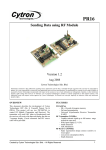
RC hobby servos are compact, low cost and great actuators for robots. The
popularity in using RC servo motors in the robotics field is due to its ability to rotate
and maintain at certain location, position or angle according to control pulses from a
single wire [6]. A RC servo motor comes with a gearbox and small motor to enable
motion. The electronic circuit embedded in the RC servo motor controls the motor
so that the output gear will move to the desired position. In short, the main reason
for choosing RC servo motors as actuators for joint movements is because they are
DC motors with built in gearing and feedback control loop circuitry where no motor
driver is needed. Degree of rotation for a servo motor is controlled by Pulse Width
Modulation. Figure 3.5 illustrates the selected type of RC servo motor.
Figure 3.5 C55R RC servo motor from Cytron
17
Specification for C55R RC servo motor:
i)
Full Metal Gears
ii)
Suitable for heavy duty application
iii)
2 Ball Bearings
iv)
Speed (sec/60deg): 0.22/4.8V, 0.20/6.0V, 0.17/7.2V
v)
Torque (Kg-cm): 9.0/4.8V, 11.0/6.0V, 13.0/7.2V (maximum 7.2V)
vi)
Size (mm): 40.8x20.18x36.5
vii)
Weight (g): 55
viii) Rotation
ix)
angle: 180 degree
Pulse width range: 0.582ms to 2.5ms (estimation)
In this project, a total of 5 servo motors are used. A servo motor is attached
to the base, elbow and wrist for rotational or link movements. For the shoulder joint,
two servo motors are used because more torque is needed to support the heavy frame
of the robotic arm at that joint.
3.4 Circuit Development
In this section, mainly the microcontroller and position sensor used will be
discussed.
18
3.4.1
Microcontroller
Microcontrollers are like mini computers that can be fit into robots. For a
robotic arm, microcontroller is the master brain that controls all the joint movements
and determines the next step to be executed.
PIC 16F877A, a powerful 200
nanosecond instruction execution yet easy-to program CMOS FLASH-based 8-bit
microcontroller produce by Microchip Technology Inc is selected to be used in this
project [7]. This microcontroller is cheap and easy available in the stores. It has
suitable functions and enough output pins for a robotic arm with 5 servo motors. The
8 channels of 10-bit analogue to digital converter is an important function for
converting the analogue output voltage received from potentiometer to a digital
signal. Figure 3.6 shows the image of a PIC 16F877A and Figure 3.7 shows the
schematic diagram of the PIC.
Figure 3.6 PIC 16F877A
19
Figure 3.7 Schematic diagram of PIC 16F877A
Below are the important features of PIC 16F877A:
i)
Pin Count: 40-pin PDIP
ii)
Program Memory: 14KB or 8K 14-bit Flash
iii)
Max Crystal Speed: 20MHz
iv)
RAM Bytes: 368
v)
EEPROM Bytes: 256
vi)
Timers: 2 x 8 bit, 1 x 16-bit
vii)
Digital Communication: 1xA/E/USART, 1 x MSSP(SPI/I2C)
viii) Capture/Compare/PWM: 2
ix)
ADC: 8ch, 10-bit
x)
Comparators: 2
x CCP
20
3.4.2
Enhanced 40 Pins PIC Start-Up Kit (SK40C)
This start- up kit is designed to offer an easy to use starter board for PIC
microcontroller users.
It comes with basic element for users to begin project
development and offers plug and use features [8]. No extra components are required
for the PIC to function thus saving development and soldering time [9]. A 12volts
0.5ampere adapter will be use to power this board. Only the UART pins will be used
to connect to the servo controller board. Figure 3.8 illustrates an image of SK40C.
Below are some of the important features that this start-up kit offers:
i)
ICSP connector for UIC00A -simple and fast method to load program.
ii)
Perfectly fit for 40 pins 16F and PIC18F PIC.
iii)
2 x programmable switch.
iv)
2 x LED indicator.
v)
20MHz crystal oscillator.
vi)
UART connection to interface with other controller or even computer.
vii)
Users are able to utilize the function of PIC by directly plugging in the
I/O components in whatever way that is convenient to user.
Figure 3.8 SK40C
21
3.4.3
8 Channels Servo Controller (SC08A)
This servo controller can control up to 8 channels of servo motors
simultaneously and independently. Each servo signal pin can generate 0.5ms to
2.5ms servo pulses. Thus, servo motors can have an angle of rotation from 0 to 180
degrees. In addition, this servo controller has a resolution of 8000 steps which is
equivalent to 0.25ms servo pulse.
The servo pulse is controlled by simply
manipulating the resolutions while writing the program to control the servo motor
movement. Besides this, user can activate or deactivate any servo channel of choice.
Moreover users are free to set the initial position of any servo channel for the next
start-up. This feature is very useful in this project since each servo motor has
different initial position at start-up. Another function of this servo controller allows
user to request the position of an individual servo. The UART here has a 9600 baud
rate. On the other hand, the small design of this board is very useful. This board has
the dimension of 49mm x 46mm. It is also possible to extend up to 16 channels by
linking together two 8 channel servo controller. Figure 3.9 shows an image of
SC08A. S1 to S8 are the 8 channels where the servo motors will be connected.
SC08A has a separated power source for the PIC operation and for powering the
servo motors. The pins RX, TX, GND and 5V are used for UART connections to the
SK40C.
Figure 3.9 SC08A
22
3.4.4
UART
Universal Asynchronous Receive/Transmit abbreviated UART is known as a
piece a piece of computer hardware that translates data between parallel and serial
forms [10]. However in the context of robotics, it is better known as a useful device
for communicating serial data between microcontroller and computer.
UART
changes incoming parallel information to serial data which can be sent on a
communication line [11].
For this project, UART is use to send data between the
microcontroller and the servo controller. The data sent each time is the size of one
byte. A minimum of 5volts supply is required for microcontroller to interface with
SK08A.
Figure 3.10 shows the schematic diagram of the connection between
SK40C to servo controller using UART interface.
Figure 3.10 Schematic diagram of UART interface
23
3.4.5
Current Booster and Voltage Regulating Circuit
This circuit plays a major role in supplying a constant 6.09V and
approximately 2.67A to the servo motors. The power source for this circuit is from a
12V and 2A adapter source.
In this circuit, LM7806 provides a constant and
regulated output of 6.09 volts. As for the power transistor (TIP 2955), it is used to
boost the extra needed current above the maximum allowable current provided via
the regulator. Current up to 1.5A will flow through the regulator, anything above
that makes the regulator conduct and adding the extra needed current to the output
load [12]. Due to the high current drawn by servo motors, components such as
regulator and power transistor will be very hot. Thus, to reduce the heat generated,
these components must be mounted on heat sinks. Figure 3.11 shows the schematic
diagram of the current booster and voltage regulating circuit.
Figure 3.11 Schematic diagram of current booster and voltage regulating circuit
24
3.4.6
Power Source
Two AC-DC adapters are used to power this project. A 12V 0.5A adapter is
used to supply power to the SK40C. A 5Vsupply will be supplied from the SK40C
to servo controller for PIC operation through UART interface. Another adapter
which supplies the 12V 2A will be connected to the current booster and voltage
regulating circuit. The regulated output power supply from this circuit will then be
fed into the servo controller to power the servo motors. Figure 3.12 illustrates the
12V 0.5A AC-DC adapter while Figure 3.13 shows the 12V 2A AC-DC adapter.
Figure 3.12 12V 0.5A AC-DC adapter
Figure 3.13 12V 2A AC-DC adapter
25
3.5
Software Programming
MPLAB IDE software is used to write programs to control the movement of
the joints. MPLAB Integrated Development Environment (IDE) is a free, integrated
Gcc-based toolset for the development of embedded applications employing
Microchip's PIC [13]. MPLAB IDE supports both assembly and C programming
languages.
3.5.1 Flow Chart for Programming
Figure 3.14 shows the flow chart to program the pick and place robotic arm
movements to pick an item from the first position and release the item at the second
position.
26
Start
Motors move to
initialize position
Switch 1 pressed
Actuator motion brings
arm to first position
Gripped (pick item)
Actuator motion brings
arm to second position
Release Grip (Place item)
Press Reset Button
Yes
End
Figure 3.14 Programming flow chart
No
CHAPTER 4
RESULTS AND DISCUSSIONS
4.1
Introduction
In this section, the overall results for the project will be presented and
explained. The results include the actual structure, circuitry and programming source
code. The pick and place process done by the robotic arm will also be shown step by
step.
4.2
Actual Robotic Arm Structure
Figure 4.1 illustrates the Actual structure of the robotic arm. The robotic arm
is build from aluminium bars and uses PCB stands to raise up the base.
28
6
5
4
2
3
1
Figure 4.1 Actual robotic arm structure
1 – Rotating base (one servo motor for base rotational motion).
2 – Left panel for the first link (one servo motor for up-down shoulder motion).
3 – Right panel for the first link (one servo motor for up-down shoulder motion).
4 – Second link (one servo motor for up-down elbow motion).
5 – Wrist (one servo motor for rotational wrist motion).
6 – Two finger gripper (one servo motor to grip and release grip operation).
29
4.3
Complete Circuitry Design
The finalized circuitry design will be presented here. The complete circuit
consist of one SK40C with one PIC 16F877A, one servo controller board, one
current booster and voltage regulating circuit and a UART connection. Figure 4.2
shows the complete circuit for this project.
5
4
1
2
Figure 4.2 Complete circuit
1 – SK40C with PIC 16F877A.
2 – Current booster and voltage regulating circuit.
3 – Servo controller.
4 – UART interface.
5 – Three pin terminals to connect servo motor to servo controller.
3
30
4.4
Complete Programming Source Code
The written programming source code for the robotic arm movements is
included at Appendix B. Please refer to Appendix B for more details and
explanations.
4.5
Pick and Place Routines
After completing the hardware, software and circuitry, the final procedure is
integrating all of them into one complete working system that can perform a pick and
place routine. The item to be picked and placed is a blue sponge with the dimension
of 4cm x 3cm x 3cm. The blue sponge surface with the white marking represents the
initial orientation of a PCB from the top view. Aside from being able to do the pick
and place routine, the wrist of the robot arm can rotate the sponge 180 degrees to
change to orientation of the sponge. At this point, the back view of the sponge
(representing the back view of the PCB) will be flipped to the top view.
Figure 4.3 shows the complete pick and place routine. Figure 4.3(1) shows
the random position of the robot arm before start-up. In Figure 4.3(2), the robot arm
moves to the preset initial position at start-up. After start-up, as shown in Figure
4.3(3), the robotic arm will move to the first position where the sponge with the
white marking surface is located to pick up the sponge. The gripper will open
slightly and then gripped the sponge. After the sponge is picked, the robotic arm
proceeds and moves to the second position. While moving to the second position to
place the sponge, the wrist actuator will rotate the gripper at 180 degrees to change
the orientation of the sponge. This is shown in Figure 4.3(4). In Figure 4.3(5), the
sponge with the altered orientation is placed at the second location. At this point, the
31
gripper will release grip to drop and place the sponge at the second location. This
routine will continue until the reset button on SK40C is pressed. When the reset
button is pressed, the pick and place robot arm will stop functioning and return to
initial position.
2
1
3
4
5
Figure 4.3 Pick and place routine
CHAPTER 5
CONCLUSION
5.1
Conclusion
In conclusion the objectives of this project are accomplished. A four degrees
of freedom automated robotic arm with a 2 finger gripper for pick and place purpose
was successfully developed and built. Throughout this project, problem solving
skills were put to use to overcome any hardware, software or circuitry problems that
arise. This project provides analytical skills training, hardware assembly training,
program writing training and circuitry design training. The hands on experiences
acquired from this project are valuable and will definitely be useful in future.
Generally, this project gives students a chance to incorporate robotic theories
and application into their projects. Future developments on projects related to the
robotic studies are a must to further enhance the robotic field in our country and
bring the robotic field to a whole new level internationally.
33
5.2
Recommendations
Even though the project is a success, there are a few limitations that can be
further improved to develop a better and more robust automated pick and place
robotic arm.
i) Hardware. Usually students opt to handmade their mechanical hardware by
themselves to safe cost. However, the structure build by students are mostly
based on assumptions without solid test and research. This results in the lack
of accuracy in the dimension and structure of the robot arm. Students can try
to incorporate off-the-shelf hardware structure into their own design for a
more solid and accurate hardware design.
ii) Actuator. The actuator used in this project is the RC servo motor. This servo
motor is limited to certain torque. Thus, it is actually not suitable to be
chosen for this project. However due to lower cost, many students chose to
use this type of motor. For future projects, more advance motors like digital
servo and stepper motor is advice to be used to provide more flexible,
accurate and precise movements.
iii) Controller. Better and more advance controller like PID controller can be
implemented in the project.
iv) Sensor. A sensor can be place at the fingers of the gripper to detect whether
the gripper is gripping the item or not. This can be a safety function to stop
the robot arm function if the item that is supposed to be gripped is dropped.
v) Image processing. Image processing can be included to enable the robot arm
to detect and change the orientation of the item to the wanted orientation by
itself. A more advance pick and place robot arm can be developed though
this.
RERERENCE
[1]
CELESTICA, http://www.celestica.com/Careers/Careers.aspx?id=916
[2]
HOBBYTRON, http://www.hobbytron.com/lynx-arm.html
[3]
M. W. Sam.. Robotic Arm with Image Processing. Bachelor Thesis.
Universiti Teknologi Malaysia; 2009
[4]
Ashraf. E., Eduardo. Y., Karen. B., and Ricardo. S.. Design and Development
of a Competitive Low-Cost Robot Arm with Four Degrees of Freedom.
Modern Mechanical Engineering. 2011. 1:47-45.
[5]
CYTRON,
http://www.cytron.com.my/viewProduct.php?pcode=RG02A&
name=Small %20Robot%20Gripper
[6]
RC Servo C36R, C40R, C55R User's Manual V1.0,Apr 2009, Cytron
Technologies Inc
[7]
PIC 16F87XA Data Sheet,2003,Microchip Technology Inc
[8]
CYTRON, http://www.cytron.com.my/viewProduct.php?pcode=SK40C
[9]
CYTRON, http://www.cytron.com.my/viewProduct.php?pcode=SK40B
[10]
WIKIPEDIA, http://en.wikipedia.org/wiki/Universal_asynchronous_receiver
/transmitter
[11]
SOCIETY OF ROBOTS, http://www.societyofrobots.com/microcontroller_
uart.shtml
35
[12]
EXTREME CIRCUITS, http://www.extremecircuits.net/2009/08/ampere-orcurrent -boostercircuit.html
[13]
Mohamad S. A .S.. Robotic Arm Functioning Using Image Processing.
Universiti Teknologi Malaysia; 2011
36
APPENDIX A1 Gantt Chart for Semester I 2011/2012
37
APPENDIX A2 Gantt Chart for Semester II 2011/2012
38
APPENDIX B Programming Source Code
// include
//=======================
# include <pic.h>
// configuration
//=======================
__CONFIG (0x3F32);
// define
//=======================
#define SW1
RB0
#define SW2
RB1
#define LED1 RB6
#define LED2 RB7
#define SER
RB2
// function prototype
//=======================
void init (void);
void init_servo_position (unsigned char channel, unsigned int position);
void on_off_cmd ( unsigned char channel, unsigned char on_off);
void delay (unsigned long time);
unsigned char uart_rec(void);
void uart_send (unsigned char data);
void position_speed ( unsigned char channel, unsigned int position, unsigned char
speed);
void patternrec();
int pattern = 0;
// initialization
//=======================
void init ()
{
39
// set I/O port for switchs and LEDs
//===========================
TRISB=0b00000011;
// 1 for input, 0 for output
TRISD=0b00000000;
// uart initialization
//===========================
SPBRG=129;
// baud rate set as 9600 for crystal with 20Mhz
BRGH=1;
// high speed option for baud rate
SYNC=0;
// asynchronous mode
CREN=1;
// enable reception
SPEN=1;
// enable serial port
TXEN=1;
// enable transmission
TX9=0;
// 8-bit transmission
RX9=0;
// 8-bit reception
LED1 = LED2 = 1;
delay(80000);
LED1 = LED2= 0;
delay(80000);
on_off_cmd (0,1);
}
void init_servo_position (unsigned char channel, unsigned int position)
{
LED1=1;
LED2=0;
unsigned char first_byte=0, higher_byte=0, lower_byte=0;
first_byte=0b10000000|channel;
higher_byte=(position>>6)&0b01111111;
8000 are greater than a byte
lower_byte=position&0b00111111;
uart_send(first_byte);
uart_send(higher_byte);
higher byte of position 0b0xxxxxxx
uart_send(lower_byte);
while (uart_rec()!=0x04)
{
RB2=1;
//position value from 0-
//second byte is the
//wait the 0x04 value from SC08A
40
delay(2);
RB2=0;
delay(18);
}
}
void main ()
{
init();
//initial position of all the servo motors at start-up
init_servo_position (8, 3750);
init_servo_position (6, 1875);
init_servo_position (5, 5000);
init_servo_position (3, 3750);
init_servo_position (2, 3750);
init_servo_position (1, 1500);
// rotating base
// right panel for first link
// left panel for first link
// 2nd link
// wrist rotation
// gripper
while(1)
{
patternrec();
while(pattern==1)
{
LED1=0; // LED to show which part of the program the robot arm is
doing
LED2=1;
// 1st position
position_speed (8, 1875, 50); // channel 8 (base rotate to 45)
delay(250000);
position_speed (5, 1250, 15); // down(first link go down)
position_speed (6, 5625, 15);
delay (250000);
position_speed (2, 0, 30); //wrist move to 0
delay (450000);
position_speed (3, 2500, 20); // 2nd link go down to 60
delay (300000);
41
position_speed (1, 900, 30); // grip open
delay(200000);
position_speed (1, 2100, 40); // grip close. smaller d number, bigger
the gap.
delay(200000);
position_speed (3, 3750, 20); // 2nd link go up to 90
delay (200000);
position_speed (5, 3125, 15); // up (first link o up)
position_speed (6, 3750, 15);
delay(400000);
//2nd position
position_speed (8, 5625, 50); // channel 8 ( base rotate to 135)
delay(250000);
position_speed (5, 1250, 15); // down (first link go down)
position_speed (6, 5625, 15);
delay (250000);
position_speed (2, 7100, 40); //wrist move to 180
delay(450000);
position_speed (3, 2500, 20); // 2nd link go down to 60
delay (300000);
position_speed (1, 900, 30); // grip open
delay(200000);
position_speed (1, 2100, 30); // grip close. smaller d number, bigger
the gap.
delay(200000);
position_speed (3, 3750, 20); // 2nd link go up to 90
delay (200000);
position_speed (5, 3125, 15); // up (first link o up)
42
position_speed (6, 3750, 15);
delay(400000);
}
}
void on_off_cmd ( unsigned char channel, unsigned char on_off)
{
unsigned char first_byte=0;
first_byte=0b11000000|channel;
uart_send(first_byte);
uart_send(on_off);
}
void delay (unsigned long time)
{
for(;time>0;time--);
}
unsigned char uart_rec(void)
{
unsigned char rec_data;
while(RCIF==0);
rec_data = RCREG;
return rec_data;
}
void uart_send (unsigned char data)
{
while(TXIF==0);
TXREG=data;
}
//wait for data
//return the data received
//only send the new data after
//the previous data finish sent
void position_speed ( unsigned char channel, unsigned int position, unsigned char
speed)
{
unsigned char first_byte=0, higher_byte=0, lower_byte=0;
first_byte=0b11100000|channel;
higher_byte=(position>>6)&0b01111111;
8000 are greater than a byte
lower_byte=position&0b00111111;
//position value from 0-
43
uart_send(first_byte);
uart_send(higher_byte);
higher byte of position 0b0xxxxxxx
uart_send(lower_byte);
byte of position 0b00xxxxxx
uart_send(speed);
speed value from 0-100
}
void patternrec()
{
if(SW1==0)
{
pattern=1;
}
else if(SW2==0)
{
pattern=2;
}
}
//second byte is the
//third byte is the lower
//fourth byte is the