1
UNIVERSITY OF NAIROBI
School of computing and Informatics
Final Report
Mobile Video streaming Surveillance System With SMS Alert
Student Number: P56/P/7841/05
Student Name: Martin Kamau Karanja
Supervisor: Professor Okelo Odongo
Project submitted as partial fulfillment of the requirement for the
MSc. Information Science.
Declaration
This research is my original work and has not been submitted for the award of degree in any other
university.
Signed………………………….
Date……………………………………
Martin Kamau Karanja
P56/P/7841/05
This research has been submitted for examination with approval as the University Supervisor.
Signed………………………….
Professor Okelo Odongo
Supervisor
Date……………………………………
ii
Dedication
This project is dedicated to my loving wife Faith. Thank you for all the support and understanding.
iii
Abstract
In the current times, Surveillance security system becomes the best solution to overcome more crime
cases in the world and also for house intrusion problem, with the real-time monitoring it has become an
effective security system. As we know, there are many types surveillance security system which are too
expensive and difficult to use such as for Closed-circuit television (CCTV). The main problem being:
The cost of hiring the required security is out of range for most people. When a security breach takes
place, unless the owner is within the premise, they are the last to be contacted which more often than not
happens to be too late for any action the owner may want to take. Sometimes a breach is by a relative
who unknowingly walked into the trap. Since the owner is not there to verify, they are incarcerated for
no reason. A human as an alarm or to respond to sound an alarm is a huge gamble for where security and
urgent response is needed.
The main objective of this project is to develop a cost effective web application that allows live
streaming on the net and on mobile phones, a mobile SMS alert system and a remote response to the
intrusion by the owner. This will empower the owner of the security system to view real-time event on
the happenings; also be able to make judgment on the kind of action to take. This approach applies
emerging open source technologies and proprietary technologies and demonstrates the effectiveness of
our design approach via actual Implementation. The SMS alert is activated through a motion sensor. The
motion sensor used in this project is a camera motion sensor.
The project is a prototype which has been successfully designed live stream from webcam, motion
sensor to detect any movement and send an SMS while the camera continues to monitor the entire scene.
It also provides an alarm sounding system that can be activated remotely by the user depending on the
judgment made upon viewing a video stream. The owner of the system has the liberty to activate or
deactivate the streaming system. A recorded video can be replayed for reference. The streaming of
recorded videos uses Video on Demand.
One of the key things noted in the development process is that the webserver to host the system should
be local at the proximity of the secure premise. The type of phone used must be flash 8 or above
enabled.
Further development is needed on the alarm trigger to a more sensitive motion sensor than a camera. A
thick mobile client can be developed to be used for better control of access to the system. The system
will be more appropriate if it is flash independent. The ISP need to embrace live streaming and provide
facilities for it.
iv
Acknowledgement
I would like to take this opportunity to express my deepest gratitude to God for the strength and wisdom
as I did my research, to my project supervisor, Professor Okelo Odongo for his support and guidance in
my project. He has provided me with great approaching and feedback every step of the way as a result of
that I have learned and grown well. Sincerely thank for the greatly involved in the progress of this work
with no tired. It would be very difficult to complete this project without the enthusiastic support, insight
and advice given by him.
I also would like to thank other member which supported me during the hard time. This thesis would
also not be possible without an assist from all of you.
My outmost thanks also to my family for always there for me. Without them, I might not be the person I
am today. Thank you.
Finally I thank the panelists (Mr. Mburu and Mr. Ruhiu) for the feedback and the patience as I
continuously requested them to accommodate my inadequacies and they did.
v
Table of Contents
Declaration .................................................................................................................................................. ii
Dedication .................................................................................................................................................. iii
Abstract ...................................................................................................................................................... iii
Acknowledgement ...................................................................................................................................... v
Table of Contents ....................................................................................................................................... vi
List of Tables ........................................................................................................................................... viii
List of Figures ............................................................................................................................................ ix
Definitions, Acronyms and Abbreviations ................................................................................................. x
Chapter One ................................................................................................................................................ 1
Introduction ................................................................................................................................................. 1
1.1 Objectives ......................................................................................................................................... 2
1.2 Problem Statement ............................................................................................................................ 3
1.3 Justification of the System ................................................................................................................ 3
1.4 The system ........................................................................................................................................ 5
Chapter two ................................................................................................................................................. 6
Literature Review........................................................................................................................................ 6
2.2 Current systems ................................................................................................................................. 6
2.2.1 Video Surveillance Webcam Software ...................................................................................... 6
2.2.2 Webcam Spy .............................................................................................................................. 6
2.2.3 Visec .......................................................................................................................................... 7
2.2.4 Mobiscope .................................................................................................................................. 7
2.2.5 SecuExpress ............................................................................................................................... 8
2.2.6 Neighborhood watch .................................................................................................................. 8
2.3 Types of Alarm System .................................................................................................................... 9
2.3.1 Home alarm system.................................................................................................................... 9
2.3.2 Monitored system....................................................................................................................... 9
2.3.4 Unmonitored system ................................................................................................................ 10
2.3.5 The electric current alarm systems .......................................................................................... 10
2.3.6 Motion detector alarms ............................................................................................................ 10
2.4 Types of cameras ............................................................................................................................ 12
2.4.1 CCTV Cameras ........................................................................................................................ 12
2.4.2 Network Cameras..................................................................................................................... 12
2.4.3 Webcam ................................................................................................................................... 13
2.5 Video streaming .............................................................................................................................. 14
2.5.2 Video Streaming and Communication Applications ............................................................... 14
2.5.3 Video Compression .................................................................................................................. 18
2.5.4 Challenges in Video Streaming ............................................................................................... 22
2.5.5 End-To-End Security and Transcoding ................................................................................... 30
2.5.6 Streaming Over Wired and Wireless Links ............................................................................. 30
2.5.7 Streaming Media Content Delivery Networks ......................................................................... 31
2.5.8 Streaming in Mobile Networks ................................................................................................ 32
2.6 The alert system .............................................................................................................................. 41
2.8 Sending SMS via computer ............................................................................................................ 43
vi
Chapter Three............................................................................................................................................ 45
Methodology and Design .......................................................................................................................... 45
3.1 Waterfall life cycle .......................................................................................................................... 45
3.2 Tools ............................................................................................................................................... 45
3.2.1 Macromedia Dream weaver ..................................................................................................... 45
3.2.2 Microsoft Visio ........................................................................................................................ 45
3.3 SERVER SIDE ............................................................................................................................... 45
3.3.1 Apache Web Server ................................................................................................................. 45
3.3.2 MySQL .................................................................................................................................... 46
3.4 Scripting Languages........................................................................................................................ 46
3.4.1 PHP (Hypertext Processor) ...................................................................................................... 46
3.4.2 Flash Action Script 3 ............................................................................................................... 46
4.0 Systems Design ............................................................................................................................... 47
4.1.1 Functional Requirements .................................................................................................... 47
4.1.2 Non Functional Requirements ................................................................................................. 47
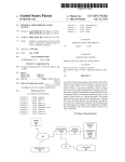
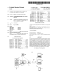
4.1 System Architecture ................................................................................................................... 48
4.4 Web Client ...................................................................................................................................... 50
4.5 The Server Side ............................................................................................................................... 51
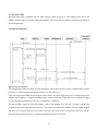
4.6 Sequence Diagram .......................................................................................................................... 51
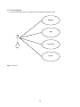
4.7 Use Case Diagram........................................................................................................................... 52
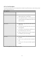
4.8 Use Case Description ...................................................................................................................... 53
4.9.1 Test Data ...................................................................................................................................... 55
4.9.1.1 Web application testing............................................................................................................. 55
4.9.1.2 Mobile Application Testing ...................................................................................................... 58
4.9.1.3 SMS Alert system ..................................................................................................................... 59
4.9.1.4 Non-Functional Testing ............................................................................................................ 60
4.9.2 Test Results .................................................................................................................................. 61
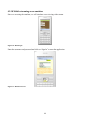
4.9.10 Mobile streaming on an emulator .............................................................................................. 64
Chapter 4 ................................................................................................................................................... 66
5.1 Discussion ....................................................................................................................................... 66
5.2 Features of the finished system ....................................................................................................... 67
5.3 Achievements .................................................................................................................................. 67
5.4 Limitations ...................................................................................................................................... 68
5.5 Future Enhancements ...................................................................................................................... 69
5.5.1 Access Control System ............................................................................................................ 69
5.5.2 One web-server Many clients .................................................................................................. 69
5.5.3 Better alert system and social network .................................................................................... 69
5.6 Discussion ........................................................................................................................................... 69
References ................................................................................................................................................. 71
Bibliography ............................................................................................................................................. 77
Appendix A: User Manual ........................................................................................................................ 77
Appendix B: Program code ....................................................................................................................... 79
vii
List of Tables
Table 1: Current Emerging Video Compression Techniques ................................................................... 21
Table 2: Web application video streaming description............................................................................. 53
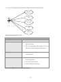
Table 3: Web application video streaming description............................................................................. 54
Table 4: A summary of tests on the web application ................................................................................ 58
Table 5: A summary of tests on the mobile application ........................................................................... 58
Table 6: A summary of tests on nonfunctional requirements ................................................................... 59
Table 7: A summary of tests on nonfunctional requirements ................................................................... 60
viii
List of Figures
Figure 1 MPEG Compression ................................................................................................................... 19
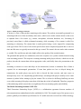
Figure 2: Mobile streaming architecture .................................................................................................. 39
Figure 3: Network Overview ..................................................................................................................... 48
Figure 4: System architecture overview .................................................................................................... 49
Figure 5: Video streaming ......................................................................................................................... 50
Figure 6: Sequence Diagram .................................................................................................................... 51
Figure 7: Use Case.................................................................................................................................... 52
Figure 8: Mobile interaction Use Case ..................................................................................................... 54
Figure 9: Attempt to view video without login .......................................................................................... 61
Figure 10: Subscription form .................................................................................................................... 61
Figure 11: Login interface ........................................................................................................................ 62
Figure 12: Live footage ............................................................................................................................. 62
Figure 13: Subscription form .................................................................................................................... 63
Figure 14: admin Login form .................................................................................................................... 63
Figure 15: Edit usesr form ........................................................................................................................ 63
Figure 16: Mobile login ............................................................................................................................ 64
Figure 17: Mobile menu view .................................................................................................................... 64
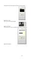
Figure 18: Live video ................................................................................................................................ 65
Figure 19: live stream ............................................................................................................................... 65
Figure 20: Sound alarm ............................................................................................................................ 65
ix
Definitions, Acronyms and Abbreviations
2G 2nd Generation mobile communications
3G 3rd Generation mobile communications
3GPP PSS 3GPP Packet-Switched Streaming
3GPP Third Generation Partnership Project
3G-SGSN 3G Serving GPRS Support Node
8PSK 8-Phase Shift Keying
AAC Advanced Audio Coding
AMR Adaptive Multi-Rate
BSC Base Station Controller
BSS Base Station Subsystem
BTS Base Transceiver Station
Codec Coder-Decoder
CS Coding Scheme
CSD Circuit-Switched Data
ECSD Enhanced Circuit-Switched Data
EDGE Enhanced Data rates for GSM Evolution
EGPRS Enhanced General Packet Radio Service
FTP File Transfer Protocol
GGSN Gateway GPRS Support Node
GGSN Gateway GPRS Support Node (a GPRS network element).
GMSK Gaussian Minimum Shift Keying
GPRS General Packet Radio Service
GSM Global System for Mobile Communications
H.263 Video codec for low bit rates standardized by ITU-T
HSCSD High-Speed Circuit-Switched Data
HTTP Hypertext Transfer Protocol
IETF The Internet Engineering Task Force
IMT International Mobile Telecommunications
IP Internet Protocol
ISHO Inter System Handover
x
ISO International Organization for Standardization
ITU International Telecommunication Union
ITU-T ITU Telecommunication Standardization Sector
MCS Modulation Coding Scheme
MPEG Moving Picture Experts Group
MS Mobile Station
MSC Mobile services Switching Centre
Node B Base station in UMTS network
NSS Network and Switching Subsystem
PCU Packet Control Unit
PDA Personal Digital Assistant
PSTN Public Switched Telephone Network
QoS Quality-of-Service
RNC Radio Network Controller
RNS Radio Network System
RTCP Real-Time Control Protocol
RTP Real-Time Transport Protocol
RTSP Real-Time Streaming Protocol
SDP Session Description Protocol
SGSN Serving GPRS Support Node
TCP Transmission Control Protocol
TDMA Time Division Multiple Access
TS Timeslot
UDP User Datagram Protocol
UMTS Universal Mobile Telecommunications System
UTRAN UMTS Terrestrial Radio Access Network
W3C World Wide Web Consortium
WCDMA Wideband Code Division Multiple Access
WLAN Wireless Local Area Network
xi
Chapter One
Introduction
In the advent of the current insecurity and the rise in inflation in the world, people have opted to take
their own security measures instead of totally depending on the police. This has seen the rise of security
companies being formed which have taken various security measures and methods to ensure safety for
the public. While this is a good thing it has come with its demerits the main ones being that the cost of
hiring the required security is out of range for most Kenyans and when a security breach takes place,
unless the owner is within the premise, they are the last to be contacted which more often than not
happens to be too late for any action.
The current trend of the home owners is to have a CCTV for record of incidences for later reference.
Others choose to have a guard watching the screen. The two ventures also have a delayed alert system to
the owner of the secure premises. It is due to these problems that have led to the development of the
Mobile Video streaming Surveillance System with SMS Alert.
The systems seek to address the two huddles that home owners face. One of them is the fact that most
CCTV systems being sold are owned by Security Company. When you requisite one, they attach to it
the security provision fee and installation fee making it out of reach for most people.
The project will utilize low cost technologies available to provide an affordable spontaneous alert and
live video system accessible anywhere. It will give the owner the power to react to a situation depending
on judgment instead of waiting for others to respond on his behalf.
Integration of technology is perhaps one of the most underutilized surveillance methods being offered as
a solution to the insecurity issues. Delivering real-time surveillance services remotely to clients with the
use of PCs and hand-held devices over the Internet is an interesting application in both the web and
mobile environment.
Almost all the security monitoring systems available do not involve the owner in the process unless its
payment of service or a robbery/breaking has taken place. This makes the owner a third party to a
system s/he should be taking ownership.
1
The alert systems, will seek intervention of another person apart from the owner. They will be loud
enough to alert neighbors or silent to alert a faraway response team. All this seem to focus on the owner
as a victim and in need of help instead of a person who can provide a solution to the immediate need.
The system developed has not only provided video recording so as to have a view of the events that took
place in your absence; it has also given live stream of the event. It does not require someone to sit
around watching a display unit to view the events. The webcam will be activated to capture the events
taking place upon the detection of a security breach. The images captured are stored in the server and an
SMS will be sent to the owners’ phone as an alert. The owner logs in to a secure site and view the events
taking place live.
The system gives an easily and affordable security for offices or anywhere security is needed. It
provides an integration of the existing monitoring security system with the modern Mobile technology.
The system is so that if the intrusion detector is activated, immediately an SMS is sent to the owner of
the setup regarding the intrusion such that the owner can open the application in his phone and view the
live video of the happenings.
The project has attempted to cut down on the cost of a security guard or a stationed observer who might
take a little break and miss an important event. It also integrates the existing ICT infrastructure to solve
surveillance problem being faced by security companies at the moment. The owner is no longer a third
party of security system in his premise but a part of the whole system. They will have the power to
determine the course of action.
1.1 Objectives
To develop a cost effective web application that has a mobile SMS alert system for the owner of the
system to view a live streaming, and respond to intrusion remotely.
2
1.2 Problem Statement
The problem with the current surveillance system is that they depend on someone employed to look at
screen to detect anomalies and alert a guard or the police.
The person paying for the security system receives information from third parties since he does not get
involved in security monitoring and response directly.
Current alert systems include:
a siren or other loud alarm noise
flashing outdoor lights
a telephone auto-dialer
All the alert methods at scaring the intruder or alerting the neighbors or a faraway security force. The
owner seems to be perceived as a victim who needs to be rescued instead of someone who can
proactively take necessary steps to curb the current predicament.
The methods have not factored in the need for the owner to be informed in time of the happenings on his
property. The owner will have to rely on accounts of the third party and a replay of recording if
surveillance video is in place. More often than not the account is distorted or it’s too late for action. The
current system seems to deliberately sideline the owner from the happenings.
1.3 Justification of the System
A monitored alarm system is a combination of the following components:
The alarm system
A Home Security Company
A telephone line or mobile phone connection
A security company, emergency personnel or police department
To work, a monitored alarm system is connected by a series of sensors or contact devices. The
complexity of the set up will depend on the size of the area being secured, so this can range from a basic
set up consisting of one or two sensors to one that uses multiple components. The system is then
connected to a telephone line or a mobile phone and a phone number is pre-programmed into the system.
3
In case of unauthorized entry, the system is tripped and a call is automatically made to the preprogrammed number, which is the number of the monitoring company. The monitoring company will
then confirm the call with the homeowner to eliminate the possibility of a false alarm. If it is confirmed,
the monitoring company will dispatch the proper authorities to your address.
Advantages
Third party involvement ensures constant Home Alarm System Monitoring. The Monitoring Company’s
offer 24/7 remote surveillance, so you are assured that your premises are kept safe, even if you are away
for extended periods of time.
Quick response from the proper authorities
Monitored alarm systems take away the inconvenience of your having to call the police, emergency
personnel or fire department yourself. This is especially helpful if you're sick, asleep or incapacitated or
just plain unable to call for help.
Option for silent alarm signal
Some monitored alarm systems use a silent alarm signal to inform the monitoring company of a possible
breaking. No audible alarm is triggered and the burglar doesn't realize his presence is already detected
until the police come. This type of alarm ensures that a burglar is caught in the act.
Maintenance
Most monitored alarm systems come with a contract that ensures regular check-up and maintenance, so
the unit you use is always reliable
Disadvantages
False alarm
Alarm systems can be triggered accidentally and thus cause unnecessary inconvenience not just to the
authorities but also to you.
4
Risk of phone line getting disabled
Wired systems rely on a working phone line to send a signal to the monitoring company. If the
telephone line is somehow disabled, it might take a while for the company to confirm the security
breach.
Cost
probably a major drawback to monitored alarm systems is the expense. Since you will be using the
services of an independent security company, expect to pay more. Other than the initial cash outlay
required for the alarm system and its installation, there are also fees to be paid which can range from
30,000 to about 50,000 a year.
1.4 The system
Mobile Alert surveillance performs automated capturing scene and provides immediate response to
suspicious events by optimizing webcam capturing parameters. I have developed a surveillance system
with motion camera sensor and webcam for capturing image. The SMS alert notifies the necessary
person of any intrusion. Upon witness of an intrusion attempt, the owner has the liberty of sounding an
alarm to scare away the intruder or draw attention.
The product is a mobile alert surveillance system that demonstrates a system capable of showing realtime video via the Internet and mobile device. Live video feed is captured on intrusion of a person at a
secured area and this is then uploaded onto a server which then streams the video. Clients are then able
to view the captured video via either a PC or a mobile device. The product has the following
specification:
A web application that offers remote access to live surveillance footage via the Internet.
A streaming server that sends real-time video feeds to the web client via a browser.
An SMS alert
A remote response system
A mobile client displays the video files that are available for viewing. System authentication that ensures
only authorized personnel are able to login and view video.
5
Chapter two
Literature Review
The project has attempted to provide security by using video as a component of a more comprehensive
security program rather than an end to itself. It offers the integration of various components to offer a
more security coverage and to provide video footage as an information base for a range of decision
support information. Remote surveillance is defined as the degree and observation required maintaining
compliance with the controls imposed and the means by which one is able to obtain information from
anywhere and whenever needed.
This section looks at the available technologies available that will underlie the Mobile Video streaming
Surveillance System with SMS Alert
2.2 Current systems
2.2.1 Video Surveillance Webcam Software
Video Surveillance Webcam Software (Basic 4 Camera) is a basic video monitoring surveillance
software with video and audio recording, time, and date stamped. It supports 1 to 4 cameras with PCI
cards. It has sound alarms with history, sound detection recording, motion detection, and time-lapse
video recording. Separate camera: brightness, contrast, sound alarms, motion detection regions, and
saved AVI files. Any: size video windows, formats NTSC PAL, any compression e.g. Windows Media
9, MPEG4, files sizes, file number, with auto file management. Has playback speed, schedules, file
backup, and can run hidden. Easy install, operation, and GUI.
Short comings
The alarm can only be heard if you are in the vicinity of the system. It has no remote access. The owner
has to consciously go to the PC to view the video stream. It requires constant monitoring.
2.2.2 Webcam Spy
The program allows to spy on your Web camera. It can be used for video surveillance and home security
system. The program supports any video source (TV tuner or web-camera). Webcam Spy features
motion detector option. You can have your own professional video security for Web camera.
Surveillance system will record video or saves snapshots for later reviewing.
6
Short comings
In as much as it is more superior in terms of accessibility than Video Surveillance Webcam Software, it
lacks an elaborate alarm system to alert the user. The user has to consciously decide to go to the internet
site and monitor. It is also not available for mobile phones.
2.2.3 Visec
With Visec, users can use any camera and a PC. Visec supports almost all cameras, including
inexpensive USB web cameras, as well as traditional analog cameras and more advanced, ip cameras,
mega pixel ip cameras and ptz ip cameras. Visec can monitor a room and record video on a user's
computer when motion is detected. Visec uses powerful algorithmic software based motion detection,
eliminating the need to buy any hardware. When motion is detected, (such as a burglar s movement)
Visec's alert system will e-mail you a picture of the motion that was detected, to a cell phone, PDA, or
computer.
Visec's video history feature allows you to playback surveillance during specified times such as when
you're away from home or out of the office. Visec features Remote Live Access allowing you to see a
live view of your home or office.
Short comings
This is much more advanced than the previous systems in that there is an email alert with an attachment
of the picture of the intruder. It is also accessible over the internet if you have a PC next to you. The
system still lacks live stream over mobile phone and an SMS alert. This therefore means that the user
has to keep checking their mail for any alerts. If the user is busy they may miss out on important
monitoring information.
2.2.4 Mobiscope
Monitor your home/office activities in real time. No need to purchase any expensive equipment. All you
need is a Web cam or a network camera connected to your computer to record everything that goes on
when you are away. Mobiscope can monitor the area for motion and transfer the video on-line to your
mobile phone.
You can use different schedules to start or end the recordings according to your preferences, for
example, start recording always at 8 a.m. when you leave home, save your recordings and watch them
later. Switch between up to 4 several Web cams.
7
Short comings
This system is better than visec and all the others covered before in that it has live stream to your mobile
phone. It retrogresses in lack of an alert system either on E-Mail or SMS
2.2.5 SecuExpress
Use SecuExpress with your Webcam to record trespassing and monitor the camera view area.
SecuEpxress is the quick and easy video surveillance software that monitors and detects the intrusion for
your personal properties. Simply install SecuExpress on your computer equipped with a Webcam and
your computer can quickly turn into a video surveillance system.
SecuExpress also provides you with an easy interface to view the camera video on computers, mobile
phones, or PDA remotely through Internet; even you are away from your SecuExpress video
surveillance system. For viewing remote video, your PDA must have Microsoft Pocket PC 2003 or 2005
version, and your mobile phone must have Microsoft Smart Phone 2003 or 2005 version.
Short comings
This system is better than all the above in terms of performance but just like most of the above systems,
it lacks an alert system either on E-Mail, SMS or any other.
2.2.6 Neighborhood watch
People often opt for cheap home security monitoring systems with lots of bells or whistles or electronic
sirens. Though installing a burglar alarm system can definitely help make you less of a target, the best
strategy may be to start a neighborhood watch. Checkout whether your home alarms is connected to the
police and a central station to ensure the response of people there.
You can get an alarm system to make sure all your windows either have contacts on them or you have
glass-break sensors in the rooms. A barking dog is a natural home security and burglar deterrent that
will prevent and frighten most burglars. If used bright and easy to identify number systems in front of
your house to help the police and any emergency services to easily locate your home during emergency.
Short comings
You have to rely on third party account and poor descriptions from a skewed source. The report is
always late and you run risk of believing a lie. The user may be too far off and may get the message
when it is too late.
8
2.3 Types of Alarm System
2.3.1 Home alarm system
A home alarm is a system that guards your home from trespassing, burglary and other kinds of dangers.
There are different types of home alarm systems available to choose from, all of them with different
operational concepts. However, they are all designed to serve just one purpose; and that is to protect
your home. These are:
1. Electric circuits
2. Motion detectors
3. Infrared alarms
2.3.2 Monitored system
This alerts a central call center if an alarm has been triggered. The call center then checks with the
homeowner to see if everything is ok by calling them. Since the call center is alerted of an alarm through
the phone wires, a clever burglar may be able to locate the outdoor phone wires if they are exposed and
cut them. By doing this, the call center is never alerted and the burglar is free to enter the home.
Another disadvantage of having your home alarm system monitored is that even after the alarm has been
set off, the burglar still has some time to get into your house, steal some valuables and escape
undetected.
This can happen because once the alarm has been set off; the security company usually waits for 30 to
45 seconds before contacting the homeowner by phone to receive a previously arranged password. They
have to wait this long to allow the homeowner time to deactivate the alarm, if it was a false alarm. If the
monitoring company does not receive the correct password, or the phone is not answered, then they
would contact the police or some other third party. An experienced thief could easily make off with
many valuables in the few minutes it takes for the police to actually arrive.
9
2.3.4 Unmonitored system
This makes a loud siren noise both inside and outside of the house when the alarm is triggered. The
responsibility to contact the police falls on your neighbors. This type of alarm system may also include
flashing lights so people are aware of where the alarm is coming from.
Advantage
1. No pay monitoring fees.
2. Burglars often become deterred when the sirens start blaring.
Their goal is to get in and get out with some valuables, and of course without being noticed. This is
made quite difficult once the alarm has been tripped.
Disadvantage
Neighbors must be home and willing to get involved by calling the police.
2.3.5 The electric current alarm systems
They can be placed in entryways all around your home such as the front door, basement door, garage
door, and windows too. These alarms will create a steady current to each of the entryways, and if there is
an intrusion, it will cause an interruption to the electrical current if someone opens a doorway without
disabling the alarm first. Generally, these types of alarms will first make some kind of loud noise, which
will hopefully scare of a burglar, or give a warning to the homeowner. This type can also have a silent
alarm that will automatically notify the police when an intrusion is detected. Disadvantage is, if there is
a blackout then there is no protection.
2.3.6 Motion detector alarms
Motion detector alarms work by sending out patterns of light or microwaves of ultrasonic sound into the
surroundings of your premise. If someone enters a protected area without first disabling the alarm, they
will create a disruption in these patterns that will automatically cause the alarm to sound. There are also
infrared motion detectors that work by detecting body heat. If there is a significant change in the
surrounding temperature in a room, it will trigger the alarm. Some of the motion detector includes:
10
Passive Infrared Detector - PIR stands for Passive Infrared. In simple terms, it is a motion detector.
PIR motion detectors are the most frequently used home security device. It usually designed to provide
an indication to an alarm panel in response to detecting IR that is indicative of motion of the object. The
alarm panel is responsive to receipt of the breach indication to cause an alarm condition occur. Excellent
performance infrared sensor for use in alarm burglar systems, visitor presence monitoring, light switches
and robots this sensors measure infrared radiation emanating from objects in the field of view.
Ultrasonic Motion Sensor -This is commonly used for automatic door openers and security alarm it
can operate with narrow beam-widths and detect motion in area where there are not supposed to be any
moving object.
In an ultrasonic motion detector, there are two transducers, one emits an ultrasonic wave and the other
picks up reflection from the different object in the area. The reflect wave arrive at receiver in constant
phase if none of the object in the area are moving. If something moves, the received signal is shifted in
phase. A phase comparator detects the shifted phase and sends a triggering pulse to alarm.
The main advantages are that they are very sensitive and extremely fast acting. However, the largest
problem with type of motion detector is that it sometimes responds to normal environmental vibration
that can be caused by a passing car or a plane overhead.
Camera motion detection
In theory, the notion beneath a motion detection camera is simple: each image captured by the camera is
compared to the previous one and if the camera detects major changes, it fires up the motion detection
alarm.
However, there are still a lot of problems connected to this tricky implementation of motion detection.
Clearly, a motion detection camera cannot be used outdoors, or even the slightest change of sunlight
may fire off the alarm. Their most common use is during nighttime when there are little natural changes
taking place that could set off false alarms.
Today’s technology isn’t superior enough to make the difference between, say, your dog, running
around the living room in the middle of the night, or a thief. Both will probably start the alarm.
Therefore, it’s a good choice to keep your pets away from the monitored vicinity during the time motion
detection is on.
11
Another constraint, or rather a fact you’ll probably want to avoid, is aiming your motion detection
camera towards a window. Even during night time, a window viewing towards the street can cause a lot
of bogus alarms as lighting outside may change, the window may mirror light in the lens and so forth.
What are good conditions for Camera motion detection?
In the best conditions you must have the following:
A well fixed camera - stability is key if you want to isolate motion
Stable light, no flickering.
Contrasting background - white objects against white background might not produce great
results.
High camera frame rate and resolution.
2.4 Types of cameras
2.4.1 CCTV Cameras
CCTV stands for Closed Circuit TV. CCTV uses one or more video cameras to transmit video images
and sometimes audio images to a monitor, set of monitors or video recorder. The difference between
CCTV and standard TV is that standard TV openly broadcasts signals to the public. CCTV is not openly
transmitted to the public. CCTV uses either wireless transmission or a wired transmission to send the
broadcast from the video cameras to the monitor(s) or recording device. Most CCTV systems are used
for surveillance which can include security monitoring, spying or for safety monitoring purposes.
2.4.2 Network Cameras
These can be analogue or digital cameras connected to a video server that has an IP address to it for
connection, thus making it possible to stream video. They have high a high resolution because of their
connection to the video server. The resolution can be as high as quad-VGA’s 1280 x 960 pixels ‘mega
pixels’. Lenses and image sensors are the components that determine the quality of the image. They can
be used to replace CCTV installations to make them networked.
IP cameras are not physically tied to your PC since they can broadcast video over a local network
(CCTV) or the Internet. Most have embedded web-servers, and some have internal motion-detection
systems. You can also find wireless IP cams that will connect directly to your Wifi network.
12
Disadvantages:
1. Cabling is still an issue since network ports are not usually in the same places as you would put a
camera.
2. IP cameras cannot be used in any other systems
3. IP cameras are almost always very poor quality cameras
4. IP cameras are nothing like as versatile as IP servers
5. You need a computer to see any video or motion snapshots
6. You never know how horrible and clunky the provided software will be.
Network cameras can be expensive, costing about the same as camcorders. Usually lacking Direct-X
drivers, they rarely work with motion detection software unless it specifically supports them.
2.4.3 Webcam
A webcam is a small camera that captures video images and can be used to store these images as video
files on a computer or to transmit the images through the Internet to another location. Webcam
surveillance uses this type of device to establish security surveillance in a given area, typically an
interior location such as an office or home, though the equipment could be used outside with proper
wiring. The benefits of using webcam surveillance are that the equipment is relatively affordable,
especially for setup in an area that already has a computer, and requires only additional software to
easily use.
2.4.3 USB cameras (“webcams”)
USB cameras, usually called “webcams”, are the quick and dirty solution to hooking a camera to your
PC. All you need is the supplied driver software, so you can be up and running in minutes. Better yet,
USB cameras are Direct-X compatible and work with almost any video capture software.
However, there are snags. Though you can connect lots of webcams to a single computer, they’re more
or less limited to arm’s reach because a USB cable is not designed for distance.
13
2.4.4 DV cameras (“camcorders”)
DV cameras – the DV stands for “Digital Video” - are the high-end solution. Often called “camcorders”,
these provide awesome image quality and a fast frame-rate. They are almost always equipped with a
zoom, and may have nice features such as night-vision. Compatible with Direct-X, they should work
with most any recent video capture software.
Like USB cameras, DV cameras are tied to your PC by cable length, this time Fire-Wire (IEEE 1394).
However, the main downside is that they’re expensive.
2.4.5 Analogue cameras
Analogue cameras belong to a whole different world. They are fast, provide images with no
compression, no artifacts, and no motion blur, and use any cable length you need. They may be
equipped with a zoom or infra-red vision. Some are wireless.
The downside of analogue cameras is that they are complicated and resource-intensive. Connecting one
to a PC requires video capture hardware. In operation, this can hog the system resources, so your PC
probably might not be able to do anything else! Many analogue cameras produce interlaced images,
requiring special – often 3rd party – software filters, which may introduce artifacts or reduce picture
quality. Overall, using an analogue camera requires a more powerful computer than a standard USB
camera would.
2.5 Video streaming
2.5.2 Video Streaming and Communication Applications
There exist a very diverse range of different video communication and streaming applications, which
have very different operating conditions or properties. For example, video communication application
may be for point-to-point communication or for multicast or broadcast communication, and video may
be pre-encoded (stored) or may be encoded in real-time (e.g. interactive videophone or video
conferencing). The video channels for communication may also be static or dynamic, packet-switched or
circuit switched, may support a constant or variable bit rate transmission, and may support some form of
Quality of Service (QoS) or may only provide best effort support. The specific properties of a video
communication application strongly influence the design of the system.
14
Streaming video may involve either on-demand or live broadcast of compressed or uncompressed video.
Most
Broadcast studio applications rely on uncompressed serial digital interface(SDI) to move video within
the studio, typically between switchers, servers, and cameras, while compressed video streams are used
in certain studio applications for video over Internet protocol. Uncompressed video streams provide low
delay and provide for reduced compression artifacts.
One-to-many (basically one-to-all) communication or broadcast communication: Broadcast is a very
efficient form of communication for popular content, as it can often efficiently deliver popular content to
all receivers at the same time. An important aspect of broadcast communications is that the system must
be designed to provide every intended recipient with the required signal. This is an important issue,
since different recipients may experience different channel characteristics, and as a result the system is
often designed for the worst-case channel. An example of this is digital television broadcast where the
source coding and channel coding were designed to provide adequate reception to receivers at the fringe
of the required reception area, thereby sacrificing some quality to those receivers in areas with higher
quality reception (e.g. in the center of the city). An important characteristic of broadcast communication
is that, due to the large number of receivers involved, feedback from receiver to sender is generally
infeasible – limiting the system’s ability to adapt.
Point-to-point or one-to-one communication: e.g. videophone and unicast video streaming over the
Internet. In point-to-point communications, an important property is whether or not there is a back
channel between the receiver and sender. If a back channel exists, the receiver can provide feedback to
the sender which the sender can then use to adapt its processing. On the other hand, without a back
channel the sender has limited knowledge about the channel.
Multicast or one-to-many is another form of communication with properties that lie between point-topoint and broadcast. Multicast is a one-to-many communication, but it is not one-to-all as in broadcast.
An example of multicast is IP-Multicast over the Internet. Multicast is currently not widely available in
the Internet, and other approaches are being developed to provide multicast capability, e.g. applicationlayer multicast via overlay networks. To communicate to multiple receivers, multicast is more efficient
than multiple unicast connections (i.e. one dedicated unicast connection to each client), and overall
multicast provides many of the same advantages and disadvantages as broadcast.
Multicast communication has received much attention in the last few years due to the significant
bandwidth savings it promises, and the challenges it presents. Consider the multicast extension of the
15
Internet, or IP multicast, as an example. When multiple clients are requesting the same media stream, IP
multicast reduce network resource usage by transmitting only one copy of the stream down shared links,
instead of one per session sharing the link. Nevertheless, besides the many practical difficulties in
supporting IP multicast for the wide-area Internet, the basic properties of multicast communication
present a number of challenges to streaming media systems.
First and foremost is the problem of heterogeneity: different receivers experience different channel
conditions and may have conflicting requirements, e.g. in terms of maximum bit-rate that can be
supported, and the amount of error protection needed. Heterogeneity is typically solved by using
multiple multicasts to provide choices for the receivers. For instance, it is possible to establish different
multicasts for different ranges of intended bit-rates. Alternatively, the different multicasts can contain
incremental information. The second challenge that a multicast present is the more restricted choice for
error control. While retransmission has been the error control mechanism of choice for many streaming
applications, its applicability in multicast has been limited by a number of challenges. Using IP
multicast for retransmission, for instance, requires that both the retransmission request and the actual
retransmission be transmitted to all the receivers in the multicast, an obviously inefficient solution. Even
when retransmissions are handled by unicast communication, scalability concerns still remain, since a
single sender will have to handle the requests of potentially many receivers.
Real-time encoding versus pre-encoded (stored) video
Video may be captured and encoded for real-time communication, or it may be pre-encoded and stored
for later viewing. Interactive applications are one example of applications which require real-time
encoding, e.g. videophone, video conferencing, or interactive games. However real-time encoding may
also be required in applications that are not interactive, e.g. the live broadcast of a sporting event. In
many applications video content is pre-encoded and stored for later viewing. The video may be stored
locally or remotely. Examples of local storage include DVD and Video CD, and examples of remote
storage include video-on-demand (VOD), and video streaming over the Internet (e.g. as provided by
RealNetworks and Microsoft). Pre-encoded video has the advantage that it does not require a real-time
encoding constraint. This can enable more efficient encoding such as the multi-pass encoding that is
typically performed for DVD content. On the other hand, it provides limited flexibility as, for example,
the pre-encoded video cannot be significantly adapted to channels that support different bit rates or to
clients that support different display capabilities than that used in the original encoding.
16
Constant-bit-rate (CBR) or Variable-bit-rate (VBR) Channel
Some channels support CBR, for example ISDN or DTV, and some channels support VBR, for example
DVD storage and communication over shared packet networks. On the other hand, a video sequence
typically has time varying complexity. Therefore coding a video to achieve a constant visual quality
requires a variable bit rate, and coding for a constant bit rate would produce time-varying quality.
Clearly, it is very important to match the video bit rate to what the channel can support. To achieve this,
a buffer is typically used to couple the video encoder to the channel, and a buffer control mechanism
provides feedback based on the buffer fullness to regulate the coarseness/fineness of the quantization
and thereby the video bit rate.
Packet-Switched or Circuit-Switched Network
A key network attribute that affects the design of media streaming systems is whether they are packetswitched or circuit-switched. Packet-switched networks, such as Ethernet LANs and the Internet, are
shared networks where the individual packets of data may exhibit variable delay, may arrive out of
order, or may be completely lost. Alternatively, circuit-switched networks, such as the public switched
telephone network (PSTN) or ISDN, reserve resources and the data has a fixed delay, arrives in order,
however the data may still be corrupted by bit errors or burst errors.
Quality of Service (QoS) Support
An important area of network research over the past two decades has been QoS support. QoS is a vague,
and all-encompassing term, which is used to convey that the network provides some type of preferential
delivery service or performance guarantees, e.g. guarantees on throughput, maximum loss rates or delay.
Network QoS support can greatly facilitate video communication, as it can enable a number of
capabilities including provisioning for video data, prioritizing delay-sensitive video data relative to other
forms of data traffic, and also prioritize among the different forms of video data that must be
communicated. Unfortunately, QoS is currently not widely supported in packet-switched networks such
as the Internet. However, circuit-switched networks such as the PSTN or ISDN do provide various
guarantees on delay, bandwidth, and loss rate. The current Internet does not provide any QoS support,
and it is often referred to as Best Effort (BE), since the basic function is to provide simple network
connectivity by best effort (without any guarantees) packet delivery.
17
2.5.3 Video Compression
Video compression is achieved by exploiting the similarities or redundancies that exists in a typical
video signal. For example, consecutive frames in a video sequence exhibit temporal redundancy since
they typically contain the same objects, perhaps undergoing some movement between frames. Within a
single frame there is spatial redundancy as the amplitudes of nearby pixels are often correlated.
Similarly, the Red, Green, and Blue color components of a given pixel are often correlated. Another goal
of video compression is to reduce the irrelevancy in the video signal that is; to only code video features
that are perceptually important and not to waste valuable bits on information that is not perceptually
important or irrelevant. Identifying and reducing the redundancy in a video signal is relatively
straightforward, however identifying what is perceptually relevant and what is not is very difficult and
therefore irrelevancy is difficult to exploit.
Image compression, such as the JPEG standard, is designed to exploit the spatial and colour redundancy
that exists in a single still image. Neighbouring pixels in an image are often highly similar, and natural
images often have most of their energies concentrated in the low frequencies. JPEG exploits these
features by partitioning an image into 8x8 pixel blocks and computing the 2-D Discrete Cosine
Transform (DCT) for each block. The motivation for splitting an image into small blocks is that the
pixels within a small block are generally more similar to each other than the pixels within a larger block.
The DCT compacts most of the signal energy in the block into only a small fraction of the DCT
coefficients, where this small fraction of the coefficients are sufficient to reconstruct an accurate version
of the image. Each 8x8 block of DCT coefficients is then quantized and processed using a number of
techniques known as zigzag scanning, run length coding, and Huffman coding to produce a compressed
bit stream. In the case of a colour image, a colour space conversion is first applied to convert the RGB
image into a luminance/chrominance colour space where the different human visual perception for the
luminance (intensity) and chrominance characteristics of the image can be better exploited.
A video sequence consists of a sequence of video frames or images. Each frame may be coded as a
separate image, for example by independently applying JPEG-like coding to each frame. However, since
neighbouring video frames are typically very similar much higher compression can be achieved by
exploiting the similarity between frames. Currently, the most effective approach to exploit the similarity
between frames is by coding a given frame by:
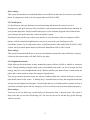
(1) First predicting it based on a previously coded frame, and then
(2) Coding the error in this prediction.
18
Consecutive video frames typically contain the same imagery, however possibly at different spatial
locations because of motion. Therefore, to improve the predictability it is important to estimate the
motion between the frames and then to form an appropriate prediction that compensates for the motion.
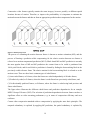
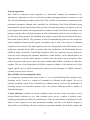
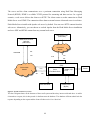
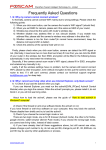
Figure 1 MPEG Compression
The process of estimating the motion between frames is known as motion estimation (ME), and the
process of forming a prediction while compensating for the relative motion between two frames is
referred to as motion-compensated prediction (MC-P). Block based ME and MC-prediction is currently
the most popular form of ME and MC-prediction: the current frame to be coded is partitioned into
16x16-pixel blocks, and for each block a prediction is formed by finding the best matching block in the
previously coded reference frame. The relative motion for the best-matching block is referred to as the
motion vector. There are three basic common types of coded frames:
(1) intra-coded frames, or I-frames, where the frames are coded independently of all other frames,
(2) Predictively coded, or P-frames, where the frame is coded based on a previously coded frame, and
(3) bi-directionally predicted frames, or B-frames, where the frame is coded using both previous and
future coded frames.
The figure above illustrates the different coded frames and prediction dependencies for an example
MPEG Group of Pictures (GOP). The selection of prediction dependencies between frames can have a
significant effect on video streaming performance, e.g. in terms of compression efficiency and error
resilience.
Current video compression standards achieve compression by applying the same basic principles. The
temporal redundancy is exploited by applying MC-prediction, the spatial redundancy is exploited by
19
applying the DCT, and the colour space redundancy is exploited by a colour space conversion. The
resulting DCT coefficients are quantized, and the nonzero quantized DCT coefficients are run length and
Huffman coded to produce the
Compressed bit stream.
VIDEO COMPRESSION STANDARDS
Video compression standards provide a number of benefits, foremost of which is ensuring
interoperability, or communication between encoders and decoders made by different people or different
companies. In this way standards lower the risk for both consumer and manufacturer, and this can lead
to quicker acceptance and widespread use. In addition, these standards are designed for a large variety of
applications, and the resulting economies of scale lead to reduced cost and further widespread use.
Currently there are two families of video compression standards, performed under the auspices of the
International Telecommunications Union-Telecommunications (ITU-T, formerly the International
Telegraph and Telephone Consultative Committee, CCITT) and the International Organization for
Standardization (ISO).
The first video compression standard to gain widespread acceptance was the ITU H.261, which was
designed for videoconferencing over the integrated services digital network (ISDN). H.261 was adopted
as a standard in 1990. It was designed to operate at p =1, 2..., 30 multiples of the baseline ISDN data
rate, or p x 64 kb/s. In 1993, the ITU-T initiated a standardization effort with the primary goal of video
telephony over the public switched telephone network (PSTN) (conventional analogue telephone lines),
where the total available data rate is only about 33.6 kb/s. The video compression portion of the standard
is H.263 and its first phase was adopted in 1996. An enhanced H.263, H.263 Version 2 (V2), was
finalized in 1997, and a completely new algorithm, originally referred to as H.26L, is currently being
finalized as H.264/AVC.
The Moving Pictures Expert Group (MPEG) was established by the ISO in 1988 to develop a standard
for compressing moving pictures (video) and associated audio on digital storage media (CD-ROM). The
resulting standard, commonly known as MPEG-1, was finalized in 1991 and achieves approximately
VHS quality video and audio at about 1.5 Mb/s. A second phase of their work, commonly known as
MPEG-2, was an extension of MPEG-1 developed for application toward digital television and for
higher bit rates. A third standard, to be called MPEG-3, was originally envisioned for higher bit rate
applications such as HDTV, but it was recognized that those applications could also be addressed within
the context of MPEG-2; hence those goals were wrapped into MPEG-2 (consequently, there is no
20
MPEG-3 standard). Currently, the video portion of digital television (DTV) and high definition
television (HDTV) standards for large portions of North America, Europe, and Asia is based on MPEG2. A third phase of work, known as MPEG-4, was designed to provide improved compression efficiency
and error resilience features, as well as increased functionality, including object-based processing,
integration of both natural and synthetic (computer generated) content, content-based interactivity.
Current Emerging Video Compression Techniques
Video Coding
Primary Intended Applications
Bit Rate
H.261
Video telephony and teleconferencing over ISDN
64kb/s
MPEG-1
Video on digital storage media(DC-ROM)
1.5Mb/s
MPEG-2
Digital Television
2-20 Mb/s
H.263
Video telephony over PSTN
33.6 kb/s and up
MPEG -4
Object-based coding, synthetic content, interactivity, Variable
Standard
video streaming
H.264/ MPEG-4
Improved video compression
100 kb/s
Table 1: Current Emerging Video Compression Techniques
The H.26L standard is being finalized by the Joint Video Team, from both ITU and ISO MPEG. It
achieves a significant improvement in compression over all prior video coding standards, and it will be
adopted by both ITU and ISO and called H.264 and MPEG-4 Part 10, Advanced Video Coding (AVC).
Currently, the video compression standards that are primarily used for video communication and video
streaming are H.263 V2, MPEG-4, and the emerging H.264/MPEG-4 Part 10 AVC will probably gain
wide acceptance.
What Do The Standards Specify?
An important question is what is the scope of the video compression standards, or what do the standards
actually specify. A video compression system is composed of an encoder and a decoder with a common
interpretation for compressed bit-streams. The encoder takes original video and compresses it to a bit
stream, which is passed to the decoder to produce the reconstructed video. One possibility is that the
21
standard would specify both the encoder and decoder. However this approach turns out to be overly
restrictive. Instead, the standards have a limited scope to ensure interoperability while enabling as much
differentiation as possible.
The standards do not specify the encoder or the decoder. Instead they specify the bit stream syntax and
the decoding process. The bit stream syntax is the format for representing the compressed data. The
decoding process is the set of rules for interpreting the bit stream. Note that specifying the decoding
process is different from specifying a specific decoder implementation.
2.5.4 Challenges in Video Streaming
Video Delivery via File Download
Probably the most straightforward approach for video delivery of the Internet is by something similar to
a file download, but we refer to it as video download to keep in mind that it is a video and not a generic
file. Specifically, video download is similar to a file download, but it is a large file. This approach
allows the use of established delivery mechanisms, for example TCP as the transport layer or FTP or
HTTP at the higher layers.
However, it has a number of disadvantages. Since videos generally correspond to very large files, the
download approach usually requires long download times and large storage spaces. These are important
practical constraints. In addition, the entire video must be downloaded before viewing can begin. This
requires patience on the viewer’s part and also reduces flexibility in certain circumstances, e.g. if the
viewer is unsure of whether he/she wants to view the video, he/she must still download the entire video
before viewing it and making a decision.
Video Delivery via Streaming
Video delivery by video streaming attempts to overcome the problems associated with file download,
and also provides a significant amount of additional capabilities. The basic idea of video streaming is to
split the video into parts, transmit these parts in succession, and enable the receiver to decode and
playback the video as these parts are received, without having to wait for the entire video to be
delivered. Video streaming can conceptually be thought to consist of the follow steps:
1) Partition the compressed video into packets
2) Start delivery of these packets
3) Begin decoding and playback at the receiver while the video is still being delivered
Video streaming enables simultaneous delivery and playback of the video. This is in contrast to file
download where the entire video must be delivered before playback can begin. In video streaming there
22
usually is a short delay (usually on the order of 5-15 seconds) between the start of delivery and the
beginning of playback at the client. This delay, referred to as the pre-roll delay, provides a number of
benefits.
Video streaming provides a number of benefits including low delay before viewing starts and low
storage requirements since only a small portion of the video is stored at the client at any point in time.
The length of the delay is given by the time duration of the pre-roll buffer, and the required storage is
approximately given by the amount of data in the pre-roll buffer.
Expressing Video Streaming as a Sequence of Constraints
A significant amount of insight can be obtained by expressing the problem of video streaming as a
sequence of constraints. Consider the time interval between displayed frames to be denoted by Δ, e.g. Δ
is 33 ms for 30 frames/s video and 100 ms for 10 frames/s video. Each frame must be delivered and
decoded by its playback time; therefore the sequence of frames has an associated sequence of
deliver/decode/display deadlines:
Frame N must be delivered and decoded by time TN
Frame N+1 must be delivered and decoded by time TN + Δ
Frame N+2 must be delivered and decoded by time TN + 2Δ
Any data that is lost in transmission cannot be used at the receiver. Furthermore, any data that arrives
late is also useless. Specifically, any data that arrives after its decoding and display deadline is too late to
be displayed. (Note that certain data may still be useful even if it arrives after its display time, for
example if subsequent data depends on this “late” data.) Therefore, an important goal of video streaming
is to perform the streaming in a manner so that this sequence of constraints is met.
Basic Problems in Video Streaming
There are a number of basic problems that afflict video streaming. Video streaming over the Internet is
difficult because the Internet only offers best effort service. That is, it provides no guarantees on
bandwidth, delay jitter, or loss rate. Specifically, these characteristics are unknown and dynamic.
Therefore, a key goal of video streaming is to design a system to reliably deliver high-quality video over
the Internet when dealing with unknown and dynamic:
1. Bandwidth
2. Delay jitter
3. Loss rate
23
The bandwidth available between two points in the Internet is generally unknown and time-varying. If
the sender transmits faster than the available bandwidth then congestion occurs, packets are lost, and
there is a severe drop in video quality. If the sender transmits slower than the available bandwidth then
the receiver produces sub-optimal video quality. The goal to overcome the bandwidth problem is to
estimate the available bandwidth and then match the transmitted video bit rate to the available
bandwidth.
Additional considerations that make the bandwidth problem very challenging include accurately
estimating the available bandwidth, matching the pre-encoded video to the estimated channel bandwidth,
transmitting at a rate that is fair to other concurrent flows in the Internet, and solving this problem in a
multicast situation where a single sender streams data to multiple receivers where each may have a
different available bandwidth. The end-to-end delay that a packet experiences may fluctuate from packet
to packet. This variation in end-to-end delay is referred to as the delay jitter.
Delay jitter is a problem because the receiver must receive/decode/display frames at a constant rate, and
any late frames resulting from the delay jitter can produce problems in the reconstructed video, e.g. jerks
in the video.
This problem is typically addressed by including a play out buffer at the receiver. While the play out
buffer can compensate for the delay jitter, it also introduces additional delay. The third fundamental
problem is losses. A number of different types of losses may occur, depending on the particular network
under consideration.
For example, wired packet networks such as the Internet are afflicted by packet loss, where an entire
packet is erased (lost). On the other hand, wireless channels are typically afflicted by bit errors or burst
errors. Losses can have a very destructive effect on the reconstructed video quality. To combat the effect
of losses, a video streaming system is designed with error control. Approaches for error control can be
roughly grouped into four classes:
1. Forward error correction (FEC)
2. Retransmissions
3. Error concealment
4. Error-resilient video coding.
The Need for Rate Control
24
Congestion is a common phenomenon in communication networks that occurs when the offered load
exceeds the designed limit, causing degradation in network performance such as throughput. Useful
throughput can decrease for a number of reasons. For example, it can be caused by collisions in multiple
access networks, or by increased number of retransmissions in systems employing such technology.
Besides a decrease in useful throughput, other symptoms of congestion in packet networks may include
packet losses, higher delay and delay jitter
To avoid the undesirable symptoms of congestion, control procedures are often employed to limit the
amount of network load. Such control procedures are called rate control, sometimes also known as
congestion control. It should be noted that different network technologies may implement rate control in
different levels, such as hop-to-hop level or network level. Nevertheless, for inter-networks involving
multiple networking technologies, it is common to rely on rate control performed by the end-hosts.
Rate Control for Streaming Media
For environments like the Internet where little can be assumed about the network topology and load,
determining an appropriate transmission rate can be difficult. Nevertheless, the rate control mechanism
implemented in the Transmission Control Protocol (TCP) has been empirically proven to be sufficient in
most cases. Being the dominant traffic type in the Internet, TCP is the workhorse in the delivery of webpages, emails, and some streaming media.
Streaming Media over TCP
Given the success and ubiquity of TCP, it may seem natural to employ TCP for streaming media. There
are indeed a number of important advantages of using TCP. First, TCP rate control has empirically
proven stability and scalability. Second, TCP provides guaranteed delivery, effectively eliminating the
much dreaded packet losses. Therefore, it may come as a surprise to realize that streaming media today
are often carried using TCP only as a last resort, e.g., to get around firewalls. Practical difficulties with
using TCP for streaming media include the following. First, delivery guarantee of TCP is accomplished
through persistent retransmission with potentially increasing wait time between consecutive
retransmissions, giving rise to potentially very long delivery time. Second, the “Additive Increase
Multiplicative Decrease” rule gives rise to a widely varying instantaneous throughput profile in the form
of a saw-tooth pattern not suitable for streaming media transport.
Streaming Media over Rate-controlled UDP
We have seen that both the retransmission and the rate control mechanisms of TCP possess
characteristics that are not suitable for streaming media. Current streaming systems for the Internet rely
25
instead on the best-effort delivery service in the form of User Datagram Protocol (UDP). This allows
more flexibility both in terms of error control and rate control. For instance, instead of relying on
retransmissions alone, other error control techniques can be incorporated or substituted. It promises the
end of wildly varying instantaneous throughput, but also the proven TCP stability and scalability.
Recently, it has been observed that the average throughput of TCP can be inferred from end-to-end
measurements of observed quantities such as round-trip-time and packet losses.
Meeting Transmission Bandwidth Constraints
The incorporation of rate control introduces additional complexity in streaming media system. Since
transmission rate is dictated by channel conditions, problems may arise if the determined transmission
rate is lower than the media bit rate. Client buffering helps to a certain degree to overcome occasional
short-term drops in transmission rate. Nevertheless, it is not possible to stream a long 200 kbps stream
through a 100 kbps channel, and the media bit rate needs to be modified to conform with the
transmission constraints.
Transcoding
A direct method to modify the media bit rate is recompression, whereby the media is decoded and then
re-encoded to the desired bit rate. There are two drawbacks with this approach. First, the media resulted
from recompression is generally of lower quality than if the media was coded directly from the original
source to the same bit rate. Second, media encoding generally requires extensive computation, making
the approach prohibitively expensive. The complexity problem is solved by a technique known as
compressed-domain transcoding. The basic idea is to selectively re-use compression decisions already
made in the compressed media to reduce computation. Important transcoding operations include bit rate
reduction, spatial down sampling, frame rate reduction, and changing compression formats.
Scalable Compression
A more elegant approach to adapt to longer-term bandwidth fluctuations is to use layered or scalable
compression. This is similar in spirit to multi-rate switching, but instead of producing multiple copies of
the same content at different bit rates, layered compression produces a set of (ordered) bit streams
Sometimes referred to as layers) and different subsets of these bit streams can be selected to represent
the media at different target bit rates. Many commonly used compression standards, such as MPEG-2,
MPEG-4 and H.263 have extensions for layered coding. Nevertheless, layered or scalable approaches
are not widely used because they incur a significant compression penalty as compared to nonlayered/non-scalable approaches.
26
Evolving Approaches
Rate control at end-hosts avoids congestion by dynamically adapting the transmission rate.
Alternatively, congestion can also be avoided by providing unchanging amount of resources to each
flow, but instead limiting the addition of new flows. This is similar to the telephone system that provides
performance guarantees although with a possibility for call blocking. With all the difficulties facing
streaming media systems in the Internet, there has been work towards providing some Quality of Service
(QoS) support in the Internet. The Integrated Services (IntServ) model of the Internet, for instance, is an
attempt to provide end-to-end QoS guarantees in terms of bandwidth, packet loss rate, and delay, on a
per-flow basis. QoS guarantees are established using explicit resource allocation based on the Resource
Reservation Protocol (RSVP). The guarantees in terms of bandwidth and packet loss rate would have
greatly simplified streaming media systems. Nevertheless, this is only at the expense of additional
complexity in the network. The high complexity and cost of deployment of the RSVP-based service
architecture eventually led the IETF to consider other QoS mechanisms. The Differentiated Services
(DiffServ) model, in particular, is specifically designed to achieve low complexity and easy deployment
at the cost of less stringent QoS guarantees than IntServ. Under DiffServ, service differentiation is no
longer provided on a per-flow basis. Instead, it is based on the code-point or tag in each packet. Thus,
packets having the same tags are given the same treatment under DiffServ regardless of where they
originate. The cost of easy deployment for DiffServ compared to IntServ is the reduced level of QoS
support. Specific ways in which streaming media systems can take advantage of a DiffServ Internet is
currently an area of active research.
Play out Buffer for Overcoming Delay Jitter
It is common for streaming media clients to have a 5 to 15 second buffering before playback starts.
Streaming can be viewed as a sequence of constraints for individual media samples. The use of
buffering essentially relaxes all the constraints by an identical amount. Critical to the performance of
streaming systems over best-effort networks such as the Internet, buffering provides a number of
important advantages:
1. Jitter reduction: Variations in network conditions causes the time it takes for packets to travel
between identical end-hosts to vary. Such variations can be due to a number of possible causes,
including queuing delays and link-level retransmissions. Jitter can cause jerkiness in playback due to the
failure of same samples to meet their presentation deadlines, and have to be therefore skipped or
delayed. The use of buffering effectively extends the presentation deadlines for all media samples, and
27
in most cases, practically eliminates playback jerkiness due to delay jitter. The benefits of a playback
buffer are, where packets are transmitted and played at a constant rate, and the playback buffer reduces
the number of packets that arrive after their playback deadline.
2. Error recovery through retransmissions: The extended presentation deadlines for the media
samples allow retransmission to take place when packets are lost, e.g., when UDP is used in place of
TCP for transport. Since compressed media streams are often sensitive to errors, the ability to recover
losses greatly improves streaming media quality.
3. Error resilience through Interleaving: Losses in some media streams, especially audio, can often be
better concealed if the losses are isolated instead of concentrated. The extended presentation deadlines
with the use of buffering allow interleaving to transform possible burst loss in the channel into isolated
losses, thereby enhancing the concealment of the subsequent losses
4. Smoothing throughput fluctuation: Since time varying channel gives rise to time varying
throughput, the buffer can provide needed data to sustain streaming when throughput is low. This is
especially important when streaming is performed using TCP (or HTTP), since the server typically does
not react to a drop in channel throughput by reducing media rate. The benefits of buffering do come at a
price though. Besides additional storage requirements at the streaming client, buffering also introduces
additional delay before playback can begin or resume (after a pause due to buffer depletion). Adaptive
Media Play out (AMP) is a new technique that enables a valuable trade-off between delay and
reliability.
Error Control for Overcoming Channel Losses
The third fundamental problem that afflicts video communication is losses. Losses can have a very
destructive effect on the reconstructed video quality, and if the system is not designed to handle losses,
even a single bit error can have a catastrophic effect. A number of different types of losses may occur,
depending on the particular network under consideration. For example, wired packet networks such as
the Internet are afflicted by packet loss, where congestion may cause an entire packet to be discarded
(lost). In this case the receiver will either completely receive a packet in its entirety or completely lose a
packet. On the other hand, wireless channels are typically afflicted by bit errors or burst errors at the
physical layer. These errors may be passed up from the physical layer to the application as bit or burst
errors, or alternatively, entire packets may be discarded when any errors are detected in these packets.
Therefore, depending on the interlayer communication, a video decoder may expect to always receive
28
“clean” packets (without any errors) or it may receive “dirty” packets (with errors). The loss rate can
vary widely depending on the particular network, and also for a given network depending on the amount
of cross traffic. For example, for video streaming over the Internet one may see a packet loss rate of less
than 1 %, or sometimes greater than 5-10 %. A video streaming system is designed with error control to
combat the effect of losses. There are four rough classes of approaches for error control:
1. Retransmissions
2. Forward error correction (FEC)
3. Error concealment
4. Error-resilient video coding.
The first two classes of approaches can be thought of as channel coding approaches for error control,
while the last two are source coding approaches for error control. These four classes of approaches are
discussed in the following four subsections. A video streaming system is typically designed using a
number of these different approaches. In addition, joint design of the source coding and channel coding
is very important.
Retransmissions
In retransmission-based approaches the receiver uses a back-channel to notify the sender which packets
were correctly received and which were not, and this enables the sender to resend the lost packets. This
approach efficiently uses the available bandwidth, in the sense that only lost packets are resent, and it
also easily adapts to changing channel conditions. However, it also has some disadvantages.
Retransmission leads to additional delay corresponding roughly to the round-trip-time (RTT) between
receiver sender-receiver. In addition, retransmission requires a back-channel, and Packet Number.
In many applications the additional delay incurred from using retransmission is acceptable, e.g. Web
browsing, FTP, telnet. In these cases, when guaranteed delivery is required (and a backchannel is
available) then feedback-based retransmits provide a powerful solution to channel losses. On the other
hand, when a back channel is not available or the additional delay is not acceptable, then retransmission
is not an appropriate solution.
There exist a number of important variations on retransmission-based schemes. For example, for video
streaming of time-sensitive data one may use delay-constrained retransmission where packets are only
retransmitted if they can arrive by their time deadline, or priority-based retransmission, where more
important packets are retransmitted before less important packets. These ideas lead to interesting
scheduling problems, such as which packet should be transmitted next.
29
Intranet
When using streaming on a corporate Intranet, it is of great importance that the streaming data being
sent over the network doesn’t interfere with the rest of the network applications. This will slow down
other traffic dramatically. To prevent this, IP multicasting is recommended, thus sending only sending
one stream of data onto the network. The users are simply instructing the computer’s network card to
listen to a particular IP address for the multicast.
Internet
Although streaming is conceivable over the Internet, streaming to a wide different variety of viewers on
various parts of the Internet reliably is a very daunting task due to the variety in how people are
connected and the quality and number of streams that would have to be created. In addition, the support
for Multicast on the Internet is very limited. Streaming on very low bitrates (<64kbps) results in smaller
video windows with lower frame rate, lower resolution, and poor audio quality.
2.5.5 End-To-End Security and Transcoding
Encryption of media is an effective tool to protect content from eavesdroppers. Transcoding at
intermediate nodes within a network is also important technique to adapt compressed media streams for
particular client capabilities or network conditions. Nevertheless, network transcoding poses a serious
threat to the end-to-end security because transcoding encrypted streams generally requires decrypting
the stream, transcoding the decrypted stream, and then re-encrypting the result. Each transcoding node
presents a possible breach to the security of the system. This problem can be overcome by Secure
Scalable Streaming (SSS) which enables downstream transcoding without decryption .SSS uses jointly
designed scalable coding and progressive encryption techniques to encode and encrypt video into secure
scalable packets that are transmitted across the network. These packets can be transcoded at
intermediate, possibly untrusted, network nodes by simply truncating or discarding packets and without
compromising the end-to-end security of the system. The secure scalable packets have unencrypted
headers that provide hints, such as optimal truncation points, which the downstream transcoders use to
achieve rate-distortion (R-D) optimal fine-grain transcoding across the encrypted packets.
2.5.6 Streaming Over Wired and Wireless Links
When the streaming path involves both wired and wireless links, some additional challenges evolve. The
first challenge involves the much longer packet delivery time with the addition of a wireless link. For
instance, round-trip propagation delay in the 3G wireless system is in the order of 100 ms even before
30
link-level retransmission. With link-level retransmission, the delay for the wireless link alone can be
significant. The long round-trip delay reduces the efficiency of a number of end-to-end error control
mechanisms: the practical number of end-to-end retransmissions is reduced.
The second challenge is the difficulty in inferring network conditions from end-to-end measurements. In
high-speed wired networks, packet corruption is so rare that packet loss is a good indication of network
congestion, the proper reaction of which is congestion control. In wireless networks however, packet
losses may be due to corruption in the packet, which calls for stronger channel coding. Since any end-toend measurements contain aggregate statistics across both the wired and wireless links, it is difficult to
identify the proper cause and therefore perform the proper reaction.
2.5.7 Streaming Media Content Delivery Networks
The Internet has rapidly emerged as a mechanism for users to find and retrieve content, originally for
webpages and recently for streaming media. Content delivery networks (CDNs) were originally
developed to overcome performance problems for delivery of static web content (webpages). These
problems include network congestion and server overload that arise when many users access popular
content. CDNs improve end-user performance by caching popular content on edge servers located closer
to users. This provides a number of advantages. First, it helps prevent server overload, since the
replicated content can be delivered to users from edge servers. Furthermore, since content is delivered
from the closest edge server and not from the origin server, the content is sent over a shorter network
path, thus reducing the request response time, the probability of packet loss, and the total network
resource usage. While CDNs were originally intended for static web content, recently, they are being
designed for delivery of streaming media as well.
Streaming Media CDN Design
A streaming media CDN is a CDN that is explicitly designed to deliver streaming media, as opposed to
static webpages. Streaming media CDN design and operation is similar in many ways to conventional
(webpage) CDN design and operation. For example, there are three key problems that arise in general
CDN design and operation.
Server placement problem: Given N servers, where should these servers is placed on the
network?
Content distribution problem: On which servers should each piece of content be replicated?
Server selection problem: For each request, which is the optimal server to direct the client to
for delivery of the content?
31
Many aspects of a streaming media CDN are also quite different from a conventional CDN. For
example, client-server interaction for a conventional (webpage) CDN involves a short-lived (fraction of
a second) HTTP/TCP session(s). However, a streaming session generally has a long duration (measured
in minutes) and uses RTSP and RTP/UDP. While congestion and packet loss may lead to a few seconds
delay in delivering a webpage and is often acceptable, the corresponding effect on a streaming media
session would be an interruption (stall or visual artifacts) that can be highly distracting. Clearly, delay,
packet loss, and any form of interruption can have a much more detrimental effect on video streaming
then on static webpage delivery. In addition, in a conventional CDN each piece of content (webpage) is
relatively small, on the order of 10’s of kilobytes, and therefore it can be replicated in its entirety on
each chosen server. However, streaming media, such as movies, have a long duration and require a
significant amount of storage, on the order of megabytes or gigabytes, and therefore it is often not
practical or desirable to replicate an entire video stream on each chosen server. Instead, the video can be
partitioned into parts, and only a portion of each video is cached on each server. There are many
interesting problems related to caching of video. Two other capabilities that are important for streaming
media CDN, and are of lesser importance for a conventional CDN for webpage distribution, are
multicast and server hand-off. Multicast is clearly a highly desirable capability for streaming of popular
media. While wide-area IP Multicast is currently not available in the Internet, a streaming media CDN
can be explicitly designed to provide this capability via application-layer multicast:
The infrastructure in the streaming media CDN provide an overlay on the Internet and are used as the
nodes for the multicast tree. Communication between nodes employs only simple ubiquitous IP service,
thereby avoiding the dependence of IP multicast. Another important capability is hand-off between
streaming servers. Because streaming media sessions are long lived, it is sometimes required to perform
a midstream hand-off from one streaming server to another. This functionality is not required for
webpage delivery where the sessions are very short in duration. Furthermore, when the streaming
session involves transcoding, mid-stream hand-off of the transcoding session is also required between
servers.
2.5.8 Streaming in Mobile Networks
The mobile phones of today have enough computing capacity, memory, and multimedia features for
advanced multimedia applications such as playing audio-visual content. These features, together with
packet-switched data services provided by GPRS, EDGE, and WCDMA networks and advanced
compression algorithms have made streaming of audio-visual content to mobile phones possible.
32
Streaming is a method of transferring digital data with real-time characteristics in such a way that the
recipient can view the content while receiving the data. The advantage of streaming compared to
downloading is that it makes it possible for the recipient to start viewing the content almost
immediately, and an entire file does not have to be downloaded and stored on the client device.
On the other hand, the quality of a presentation is constrained by the underlying network. Since
streaming is sensitive to interruptions, it is important to understand the properties of the transport
network when developing streaming services for mobile networks. These technologies include GPRS,
EDGE, and UMTS mobile systems.
In mobile streaming, interoperability between different streaming components is very important. The
components can be divided in three categories: servers, encoders, and players. To ensure
interoperability, standardized file formats, codecs, and protocols are needed. Most major software
providers have adopted standardized technologies instead of supporting proprietary solutions. The
MPEG-4 standard can be used for file formats and codecs, and the 3GPP PSS standard for the entire
mobile streaming framework.
Packet-Switched Data in Mobile Networks
Global System for Mobile communications (GSM) is a digital mobile phone system taken into use in
1991. The focus was to develop a modern, standardized, digital mobile system to replace old analog
systems incompatible with each other. The GSM technology family is constantly evolving, and there
have been many additions to the basic technology. Today many of these improvements concern mobile
data services and the mobile Internet. Presents the architecture of a dual 2G/3G network built on GSM
network technology.
Basics of GSM Technology
GSM is based on cellular radio network architecture. In cellular networks, the whole coverage area is
divided into numerous smaller regions called cells. A cell is basically defined as the geographical area in
the radio coverage of one Base Transceiver Station (BTS). Mobile Stations (MS) (usually mobile
phones) communicate with the mobile network through the radio interface between the MS and the BTS.
Mobile stations can seamlessly move from one cell to another. The situation where a mobile station
changes cells is referred to as a handover.
A GSM network can be roughly divided to Network and Switching Subsystem (NSS) and Base Station
Subsystem (BSS). Mobile stations are connected to NSS through BSS's radio interface. NSS is usually
furthermore connected to other networks such as a fixed-line telephone network. BSS consists of
33
numerous Base Transceiver Stations (BTS) controlled by Base Station Controllers (BSC). BTS is
typically a radio antenna tower combined with a small shack containing the equipment. In rural areas,
BTSs are typically located in high locations to maximize radio coverage and thus cell size. In dense
urban areas, BTSs are often located on walls or rooftops to maximize cell capacity. BTSs are connected
to BSCs using fixed-line connections. One BSC can control multiple base stations. BSC's function is to
control the usage of radio interface resources in its area NSS consists of Mobile services Switching
Centers (MSC) and numerous registers related to it. Every BSC is connected to a MSC with a fixed-line
connection or a radio transmission line. MSCs are responsible for switching and routing connections
between mobile stations and devices in other networks. They also route and switch connections inside
the GSM core network between MSCs, as well as in the MSC between different BSCs. MSCs can be
connected to external networks such as the Public Switched Telephone Network (PSTN) or other
operators' GSM networks.
There are four main versions of the GSM radio interface: GSM-900, GSM-1800, GSM-850, and GSM1900. The number indicates the radio frequency (MHz) used. Europe and most of the world uses GSM900 and GSM-1800, but in the United States and Canada, GSM-850 and GSM-1900 are used. Modern
GSM phones usually support two or three frequency bands.
Time-Division Multiple Access (TDMA) technology is used to share radio channels between multiple
mobile stations. Radio channels are divided to frames which are furthermore divided to short timeslots
(TS). Each user has their own timeslots and this way they can have access to the full channel bandwidth
for a short period at a time. Circuit-Switched Data Services In addition to voice calls, GSM technology
provides support for data calls. By using a Circuit-Switched Data (CSD) service, a GSM phone can be
used like a modem to transfer arbitrary digital data. Because GSM is already a digital system, there is no
need to modulate data from digital to analogue and back, like traditional modems do. Circuit switching
means that after the data call has been established, the user has a synchronous data channel in
continuous, exclusive use until either the caller or the recipient disconnects it. The bit rate for user data
in GSM is 9.6 kbps. Because the original bit rate of CSD is quite low, some improvements have been
developed to achieve higher bit rates. By using High-Speed Circuit-Switched Data (HSCSD)
technology, a mobile station can use multiple timeslots (usually 2 or 4) grouped to one logical channel.
By using 4 timeslots, bit rates as high as 38.4 kbps can be achieved. In addition, the bit rate per one
timeslot can be raised from 9.6 to 14.4 kbps by using enhanced channel coding technique which lowers
34
the number of bits used for error correction. Therefore, the maximum bit rate using 14.4 kbps channel
coding and 4 timeslots is 57.6 kbps.
General Packet Radio Service (GPRS)
General Packet Radio Service (GPRS) is an add-on to existing GSM networks providing an option to
use packet switched protocols (usually IP) for transferring data. GPRS is focused only on transferring
packet data, while the existing GSM network can still be used for circuit-switched voice and data calls.
GPRS requires modifications and additions to mobile network elements, as well as support from mobile
terminals GPRS is an integral part of third-generation (3G) mobile networks, and it is used for both
voice and data services in 3G mobile networks such as UMTS.
The main features of GPRS are speed, immediacy, and better utilization of network resources. Higher
data rates are achieved using multiple timeslots simultaneously and using more efficient channel coding
algorithms. Immediacy means that there is no need for dial-up procedures as when using CSD. Data can
be transferred almost immediately upon need for it and the mobile station is in radio coverage. Users are
not necessarily billed for connection time anymore, but by the actual amount of transferred data. Also,
the usage of radio resources is more efficient and flexible since GPRS users can share timeslots left over
from circuit-switched connections. This way GPRS also improves the peak time capacity of base
stations.
GPRS Network Architecture
GPRS has been designed so that it can be added to an existing GSM network with as few changes to
base stations as possible. This is important to network operators, as the base station subsystem
represents a huge share of the network hardware. BTSs require usually only software updates and
existing connections to BSCs can also be used with GPRS.
BSCs require both new software and hardware. Packet Control Unit (PCU) is a new unit in BSC used
for separating packet data from circuit-switched connections, and forwarding them to the proper
networks. Circuit-switched connections are still directed to the GSM network through MSC, while
packet data is directed to the GPRS backbone network through a new network element called Serving
GPRS Support Node (SGSN). The GPRS backbone is a high-speed packet-switched IP network
connecting Serving GPRS Support Nodes (SGSN), Gateway GPRS Support Nodes (GGSN), and
operators’ GPRS networks together.
35
SGSN is a GPRS network element on the same logical level as MSC in the GSM network. The primary
function of SGSN is to deliver packets between the network and mobile stations within its service area.
SGSN also tracks the mobile stations' locations in the network, processes registrations, and checks
network access for mobile stations. SGSN is connected to the base stations subsystem by a Frame Relay
connection between SGSN and the PCU unit of BSC. SGSN can be physically integrated to BSC.
GGSN is a gateway element used for connecting the GPRS backbone to external IP networks such as the
public Internet, other operators' GPRS networks, or intranets. GGSN is shown to an external network as
an IP router. GGSNs are separated from external networks by firewalls. GGSNs also maintain the
routing information necessary to route packets to mobile stations through correct SGSN nodes.
GPRS Mobile Stations
New mobile terminals are required for taking advantage of GPRS, because old GSM phones are not able
to handle packet data or the new enhanced air interface. All GPRS terminals must be backward
compatible with GSM which they use for circuit-switched services. GPRS terminals are categorized to
Class A, B, and C devices. Class A devices support simultaneous usage of GPRS packet data and
circuit-switched voice calls. Class B devices can automatically switch between GPRS packet data and
GSM circuit switched services, but they cannot be used simultaneously for transferring data. GPRS is
switched to busy mode while there is an active circuit-switched connection. For Class C devices, the
user must select the used service manually and the other service is unreachable. Currently available
terminals are mostly Class B devices. Most GPRS devices are mobile phones, but there are also more
specialized devices such as PDAs with an embedded GPRS phone and card modems for laptops.
Channel Coding Schemes and Multi slot Classes
GPRS provides data-rates up to a theoretical maximum of 171 kbps. The highest data-rates are achieved
using up to eight timeslots simultaneously and channel coding algorithms with reduced error correction,
when possible. There are four different channel coding schemes called CS-1, CS-2, CS-3, and CS-4. The
coding scheme used depends on the quality of radio link between the mobile station and the base station.
CS-1 is used in poor radio environments, as it has the most effective error correction. CS-4 does not
have any error correction and it can be only used in very good conditions. CS-2 is equivalent to the
channel coding used for GSM CSD services. The bit rates for coding schemes are presented in Table
2.1. GPRS mobile stations must support all coding schemes, but for base stations only CS-1 is
mandatory. Currently, mostly CS-1 and CS-2 are used in practice in actual mobile networks.
36
The device's multislot class determines the maximum number of timeslots for downstream, upstream,
and total. For example, a device with multislot class 10 can utilize up to 4 timeslots for downstream, up
to 2 for upstream, but only 5 timeslots can be used at a time. This makes configurations with 4+1 or 3+2
timeslots possible for downstream and upstream, respectively. The theoretical maximum of
simultaneous timeslots is eight, but currently there are no devices capable of that. Using more timeslots
requires more processing capability and power consumption also becomes higher. Devices with higher
multislot classes are also more complex and thus more expensive. Recent devices can typically utilize 3
or 4 timeslots for downstream and 1 or 2 for upstream. Using the normal CS-2 coding scheme,
theoretical data rates up to 40.2 kbps (3 timeslots) and 53.6 kbps (4 timeslots) can be achieved. It must
be noticed that these bit rates are not effective transfer rates for user data, but raw bit rates that can be
transferred on a radio link using CS-2 channel coding. Bit rates for user data are lower due to packet
overhead.
Universal Mobile Telecommunications System (UMTS)
Universal Mobile Telecommunications System (UMTS) is one of third generation (3G) mobile systems
defined in International Mobile Telecommunications 2000 (IMT-2000) standard by International
Telecommunications Union (ITU). UMTS is designed especially for the needs of broadband mobile
Internet and other packet-switched services offering data-rates up to 2 Mbps in optimal radio conditions
indoor.
UMTS uses completely different radio interface than GSM/GPRS called Wideband Code Division
Multiple Access (WCDMA). Mobile stations share the same radio frequency, and they are separated
from each other by hash codes. Time division, such as in TDMA, is not used and thus there is no
concept of a timeslot anymore. Because the WCDMA radio interface is not compatible with TDMA,
UMTS networks require a completely different base station subsystem than GSM/GPRS networks. It is
called UMTS Terrestrial Radio Access Network (UTRAN). However, UMTS uses the same GPRS core
network as GSM/GPRS systems. UMTS compatible mobile stations are also backward compatible with
GSM/GPRS and they can be used if UMTS is not available. UMTS also features handovers between
UMTS and GSM/GPRS networks, so mobile stations can change networks without a noticeable break in
the connection. It is believed that UMTS will be implemented only in cities in the first phase, while rural
areas will be handled with existing GSM/GPRS/EDGE systems. Handover between the different
network technologies is called inter-system handover (ISHO).
UMTS Features
37
One of the key features of UMTS is speed. UMTS improves data-rates clearly from earlier 2G mobile
systems. UMTS target data rates are 144 kbps for rural outdoor areas, 384 kbps for urban outdoor areas,
and 2048 kbps for indoor and close range outdoor areas. One of the new features, Quality of Service
(QoS), allows the network to provide different class of service for different needs. UMTS specifies four
QoS classes. Conversational class is for highly interactive and real-time services with low response
times and high throughput like voice, video telephony, and real time gaming. Streaming class is for
transferring multimedia content to mobile stations. Interactive class is for web browsing, non-real-time
network gaming, and other services that do not need low response times. Finally, background class is for
services that do not have strict demands for performance. By using QoS, network resources can be better
shared between users taking their requirements into account. QoS classes can also be used as a basis for
billing. Because higher QoS classes likely reserve more network resources and offer better user
experience they can be priced differently.
UMTS Network Architecture
UMTS Terrestrial Radio Access Network (UTRAN) can be added to an existing 2G network in parallel
to a GSM radio access network. UTRAN and GSM BSS share the same GPRS core network. The
UTRAN architecture is quite similar to the GSM radio access network. UTRAN contains Radio
Network Systems (RNS) each controlled by Radio Network Controller (RNC). RNC basically
corresponds to BSC in GSM. RNCs are connected to MSC and 3G-SGSN. Normal SGSN cannot be
used since RNC has a different interface from BSC. Base station in UTRAN is called Node B. Each
RNC is connected to multiple base stations. Each base station can provide service for multiple cells.
Streaming in Mobile Networks
The term mobile streaming is used if the content is streamed to a terminal over a mobile phone network.
A terminal is usually a mobile phone, PDA or laptop with the packet-switched data capabilities and
streaming media player software. The architecture is basically the same as used in broadband streaming,
but the clients are connected to the Internet and the streaming media server through a mobile network.
38
Figure 2: Mobile streaming architecture
A stream is a flow of data packets containing media content. The packets are normally generated by a
streaming media server from an arbitrary data source, which can be media content stored on the server
or captured from a live source (e.g. camera, microphone, television broadcast, etc.). Streaming of
previously stored data is called on-demand streaming, while streaming of live content is called live
streaming or webcasting. The content data is usually packed using a codec targeted for compressing
such type of data. The bit rate of the stream specifies how much compressed payload data is sent in a
time unit. Bit rates are typically measured in bits per second. The stream's bit rate can be either constant
or variable. The used bit rate and codec highly affect to the quality of the encoded content.
The generated data packets are continuously sent to the recipient over a packet-switched network using
some streaming protocol. The recipient is running streaming media player software, which receives the
packets, decodes the content data with an appropriate codec, and finally shows the presentation to the
user.
Streaming is sensitive to errors and delays in the transmission, because a continuous flow of data is
required for an uninterrupted presentation. If some data packets are lost or delayed during the
transmission, the media player may not be able to decode the data correctly, and some errors or
interrupts may occur. For compensating possible delays, streaming media players usually receive some
amount of packets before starting to play the content. This is referred as buffering. Buffering can also
occur while streaming if the player runs short of the data due to lack of bandwidth. Therefore, properties
of the underlying mobile network have an significant effect on streaming quality and reliability.
The Mobile Streaming Standard: 3GPP PSS
Third Generation Partnership Project (3GPP) is a collaboration agreement between numbers of
telecommunications standardization bodies established in 1998. The original scope of the project was to
produce globally used technical specifications for 3G mobile networks evolved from GSM technology,
39
but currently also the maintenance and development of the original GSM technology is included in the
project. The information provided in this section is mainly based on. 3GPP Packet Switched Streaming
(3GPP PSS) is a specification defining a framework for interoperable, end-to-end streaming services in
packet-switched mobile networks. 3GPP PSS highly reuses the work done by the organizations such as
The Internet Engineering Task Force (IETF), World Wide Web Consortium (W3C), Motion Picture
Experts Group (MPEG), and International Organization for Standardization (ISO), and International
Telecommunication Union (ITU). Packet-switched streaming was first introduced in 3GPP Release 4.
3GPP PSS Release 4 (frozen in March 2001) defines a basic framework, protocols, codecs, and the
3GPP file format. 3GPP PSS itself does not specify the coding of content data, but utilizes already
standardized codecs, formats, and data types. By 3GPP Release 4 specification, the AMR and MPEG-4
AAC codecs are used for encoding audio, and the H.263 and MPEG-4 codecs for encoding video.
Release 6 will introduce some additional codecs. 3GPP PSS is widely supported by a majority of the
streaming platform providers such as RealNetworks, Apple, and Packet Video. It is also implemented in
many mobile phones on the market. This makes 3GPP currently the most important mobile streaming
standard applicable today.
Real-Time Transport Protocol (RTP)
Real-time Transport Protocol (RTP) [10] provides functions for end-to-end transport of real-time data,
such as audio, video, multimedia, or other content. RTP supports both unicast and multicast
transmissions. RTP is only a transport protocol, and thus it does not guarantee any quality of service for
the transported services. RTP is independent of the underlying transport protocols and networks, but
when it is used for streaming audio and video content in IP networks, it is usually transferred over
UDP/IP protocol.
40
Real-Time Control Protocol (RTCP)
Real-Time Control Protocol (RTCP) is used in association with the RTP protocol to provide feedback on
the quality of the transport, and for adding minimal identification and control functions. RTCP uses the
same distribution channel as RTP, so the underlying transport protocol must provide some kind of
multiplexing for the RTP data and the RTCP control packets. For example, over UDP this is typically
done simply directing the RTP and RTCP packets to different UDP ports. The primary function of
RTCP is to provide feedback for other participants of the streaming session. Adaptive encoders and
streaming servers can utilize the feedback information for adjusting the stream to match the current
transport quality. Feedback is delivered in RTCP sender and receiver reports.
Real-Time Streaming Protocol (RTSP)
Real-Time Streaming Protocol (RTSP) is an application-level protocol used for establishing and
controlling either a single or several time-synchronized streams of continuous media content, such as
audio and video. RTSP is not typically used for delivering the payload data itself, although it is possible.
To interleave the payload data with RTSP, usually protocols such as RTP are used. Basically RTSP can
be thought as a “network remote control” for multimedia servers. RTSP protocol is a text-based protocol
resembling Hypertext Transfer Protocol (HTTP), but there are also some major differences. The biggest
differences are that RTSP is not a stateless protocol like HTTP, since an RTSP server has to maintain its
state in almost all cases, and that both the server and the client can issue requests. RTSP is highly
independent of the used transport protocol and thus the RTSP session is not related to e.g. TCP, UDP or
other connections used for the transportation.
2.6 The alert system
The alert system is what notifies a person of intrusion. It ranges from very subtle silent blinking alarm to
noisy light blinking scary alarms all setup with a particular intent. Some existing types include:
a siren or other loud alarm noise
flashing outdoor lights
a telephone auto-dialler
The first two are meant to alert the neighbours, the owner and scare away the intruder. The telephone
auto dial will:
Dial the police and play a pre-recorded message over and over again; giving the address of the
house and any other relevant information.
41
Dial the security company that installed the equipment. In this case, the control box can feed
specific information about the intrusion -- which circuits or motion detectors were activated, etc.
The security company then relays this information to the police.
In this project I propose a SMS alert that goes to predefined phone, warning the owner of intrusion. The
owner can preview the intrusion before making a move to alert the authorities. The system can be used
in combination of other systems. In all the above systems, you will find that the owner has no control on
if to notify the authority or not. The Alert system is dependent on response of either a security company;
which charges really high and on a monthly basis whether there was an attack or not. Some alert systems
depend on the good will of the neighbor especially the noisy alert systems. This is not dependable
especially if the alarm proves to be false once or twice. This will deter the good neighbors from
responding as expected.
The proposed system seeks to give the user the power to decide on how to act upon intrusion. The owner
will be able to view the intrusion as it happens and if it took place before he could stream, then a play
back will be provided. Upon viewing, the owner will decide on how to react. I will attempt to provide a
response system to give the user the power to react to the attempted robbery. In some cases, especially
where the alarm alerts a security company, the company takes up to 30 minutes to respond. In this
period, the house owner who may not be in at the time, will find all the valuable items taken and will
only get to know about this several hours after the incidence. Most systems are installed by security
companies with the aim of making profits. They are tailored so that the owner only gets involved when
paying for the services or if a break-in goes wrong. The project will seek to cut down on cost through
eliminating a monitoring guard and some of the services in which the security companies charge. It
seeks to give the owner complete charge of the security system in their premises so that they determine
the kind of response to implement upon intrusion. This will enable the much needed security to be in the
reach of the majority.
42
2.8 Sending SMS via computer
There are two ways of sending SMS messages from a computer to a mobile phone. These are:
a) Using a Mobile Phone or GSM/GPRS Modem
By connecting a mobile phone or GSM/GPRS modem to a computer and using the computer and AT
commands to instruct the mobile phone or GSM/GPRS modem to send SMS messages.
A valid SIM card from a wireless carrier is placed into a mobile phone or GSM/GPRS modem which is
then connected to a computer. Connection to the computer can be made via serial cable, USB cable, a
Bluetooth link or an Infrared link.
The mobile phone or GSM/GPRS modem can be controlled by sending instructions, called AT
commands to it. These commands then control the sending and receiving of SMS messages.
A major drawback is that the SMS sending rate is too low i.e. only 6-10 SMS messages can be sent per
minute and is independent of the connection used and whether a mobile phone or GSM/GPRS is used.
b) SMS Centre or SMS Gateway
An SMS Gateway device is not a true "device", but a way of sending SMS type data to any device. To
manage a device, a plug-in and the device agent for SMSGateway devices are needed. The plug-in is
programmed as a servlet and resides on the Device Manager server. The plug-in is installed with Device
Manager. The SMSGateway plug-in is responsible for communication between the Device Manager
server and the SMSGateway.
There are different types of SMS gateway services which are commonly used by SMS application
providers. The important types of service mechanisms commonly used by SMS Gateways are ‘push
messaging services’ and ‘push pull messaging services’. In push messaging services, organisations or
business service firms, can send information to a group of customers by sending messages through SMS.
Push pull messaging service available through SMS gateway is a kind of two way communications. The
authorized customers of an enterprise can send query through message for information and pull back the
data from the enterprise by receiving SMS. Push messaging is the popular form of SMS gateway
service, as it is used by many business firms to send announcements and notifications to their customers
By connecting the computer to the SMS Centre (SMSC) or SMS gateway of a wireless carrier or SMS
service provider and sending SMS messages using a protocol or interface supported by the SMSC or
SMS gateway. The gate way used in this an open source gateway developed by source forge. Gammu is
a project which encompasses applications, scripts and drivers for managing various functions on cellular
43
phones and similar devices. It is a stable and mature codebase with support for many models available
on the market and provides functions unavailable in other similar projects.
44
Chapter Three
Methodology and Design
3.1 Waterfall life cycle
This is the classic approach to systems development life cycle. It demonstrates a development method that is
sequential and linear.
It has specific milestones for each phase of development. There is no turning back once a phase is completed, the
development proceeds.
Development takes place in strict order from concept, through design, testing, installation, troubleshooting ending
with maintenance and operation. No overlapping takes place.
It does not allow for reflection or revision; once in the testing stage, there is no going back to changing something
that was not well thought out earlier.
3.2 Tools
3.2.1 Macromedia Dream weaver
This is a web development tool. It contains features such as layers, timelines and tables to help the user create
complex and very dynamic web pages. It provides the user with the choice of alternating between HTML code
and the design view.
3.2.2 Microsoft Visio
This is a UML diagramming tool. It will be used all through the child monitoring system development. As the
name suggests, it is a Microsoft tool. Apart from UML diagramming, it can be used to design many other
demonstration diagrams.
3.3 SERVER SIDE
3.3.1 Apache Web Server
This is a server that is maintained by the Apache Software Foundation and is currently the most popular web
server due to its stability, efficiency, portability, security and small size and provides HTTP services in sync with
the current HTTP standards. It’s a free and open source product that is available for a wide variety of operating
systems including UNIX, Linux, Mac OS, and Microsoft Windows. It’s most notable for playing a role in the
initial growth of the World Wide Web.
45
3.3.2 MySQL
This is a robust and scalable relational database management system. It’s a multi-user, multithreaded database
server that uses SQL to interact with and manipulate data. MySQL features include:
Multithreading capabilities that enable the database to perform multiple tasks concurrently and allowing
the server to process client requests efficiently.
Supports various programming languages (C, C++, Java, Perl, PHP, ColdFusion, Python etc)
Implementations of MySQL are available for different platforms i.e. Windows, UNIX, Linux, and Mac
OS.
Allows users to manipulate data by providing full support of functions and operators.
It increases the efficiency of retrieving accurate and necessary information by use of a query.
Has the ability to handle large databases
3.4 Scripting Languages
3.4.1 PHP (Hypertext Processor)
This Language is appropriate for this project due to extensive use of remote execution. PHP is purely a server
side programming language that is able to make system calls. With the right windows API calls, I was
able to sound an alarm remotely and control the video encoder.
This is a server side scripting language as well as an object oriented programming language. Programmes in PHP
can be embedded inside of HTML pages. For easy maintenance and fast development time. It is associated with
Apache www server and is the most popular scripting language on the internet. It runs on many different
platforms. This language is based on C in the UNIX environment. Strength of PHP is its inclusion of a large
number of library routines. The PHP files end with .PHP extension. It supports variables such as arrays, flow
control structures and variables. PHP variables do not require specific declaration and they always start with $.
The variables do not have types. They are converted automatically. PHP has excellent support of MySQL
database, XML and Java among others.
3.4.2 Flash Action Script 3
ActionScript is an object-oriented language originally developed by Macromedia Inc. (now owned by
Adobe Systems). It is a dialect of ECMAScript (meaning it has a superset of the syntax and semantics of
the more widely known JavaScript), and is used primarily for the development of websites and software
targeting the Adobe Flash Player platform, used on Web pages in the form of embedded SWF files. The
language itself is open-source in that its specification is offered free of charge and both an open source
compiler (as part of Adobe Flex) and open source virtual machine (Mozilla Tamarin) are available.
46
ActionScript was initially designed for controlling simple 2D vector animations made in Adobe Flash
(formerly Macromedia Flash). Initially focused on animation, early versions of Flash content offered
few interactivity features and thus had very limited scripting capability. Later versions added
functionality allowing for the creation of Web-based games and rich Internet applications with
streaming media (such as video and audio). Today, ActionScript is suitable for use in some database
applications, and in basic robotics, as with the Make Controller Kit.
Flash MX 2004 introduced ActionScript 2.0, a scripting programming language more suited to the
development of Flash applications. It is often possible to save time by scripting something rather than
animating it, which usually also enables a higher level of flexibility when editing.
The live video stream application has been developed using AS3. It has libraries that enable net
connection.
4.0 Systems Design
Below are the requirements for the Mobile Alert Surveillance System that will be used as the basis for
the system development.
4.1.1 Functional Requirements
This project requires a video source that provides the video footage i.e. a camera with a connection of
some type is needed. The user must have the ability to login/logout for security reasons. An alert in the
form of an SMS that informs a user that an intrusion or security breach has occurred is one of the key
focuses of this project to eliminate the cost of a guard. The web based application that offers user’s
access to real-time video footage is appropriate for ease of access at any locality. The web client gets
access to surveillance footage via a web browser. The system has to have a mobile access provision that
offers users access to real-time video footage. An access mechanism within the system that provides
allows the user to sound alarm in case of intrusion to empower the user to react accordingly based on
judgment. A way to start and stop streaming to the secure are for the user if need be will be provided to
allow the user to switch off the system if not needed.
4.1.2 Non Functional Requirements
The client application should have minimal reliance on the network in terms of any computations
performed or any data transfers. The system should be usable and easily learnable. Novice users should
be able to easily interpret intuitive menu commands without the need of a user manual. The system
should provide for minimal delay in the transmission of video from the source of breach to the user. The
47
system should provide real-time video feed to the user. The client application should be light on
resources. It should be able to operate on handheld devices with limited processing and memory
requirements. Should the server application be offline for any reason, the client application should
provide appropriate error messages to its users in a clear, concise and non-ambiguous manner. It should
allow for secure data passing and low memory usage. A sensor that triggers the camera on when an
intrusion occurs would be a great addition but was not provided for this project. The system should be
able to alert the user on intrusion of a secured area.
4.1 System Architecture
The diagram below shows the network topology of the system. Once a frame has been captured by the
camera, it’s sent to the encoder. The streaming server then uses multicast and to stream the video. The
web application in the server has a video player application which can be accessed through a web
browser in the LAN or anywhere with internet access. Mobile devices needs a flash plugin to be able to
stream.
Figure 3: Network Overview
48
The server and the client communicate over a persistent connection using Real-Time Messaging
Protocol (RTMP). RTMP is a reliable TCP/IP protocol for streaming and data services. In a typical
scenario, a web server delivers the client over HTTP. The client creates a socket connection to Flash
Media Server over RTMP. The connection allows data to stream between client and server in real time.
Flash Media Server installs with Apache web server by default. You can serve HTTP content from this
web server. Alternatively, you can choose to exclude Apache from the Flash Media Server installation
and serve SWF and HTML content from any external web server.
Client running on PC
(Web browser)
Mobile Device with Client
Application
(Web browser)
Communication
Network
SMS
GPRS/GSM
Video
Video
HTTP
SMS
Web Server
Web Application
(PHP)
Communication
Network
Video Streaming
Server
(Flash Media Server)
HTTP
SMS
SMS Gateway
(GAMMU) (Open
source)
Video
Alarm RESPONSE
Database Server
(MySQL)
Figure 4: System architecture overview
The above diagram shows all the elements of the overall system and how they interact with each other. A mobile
client makes a request; this is then passed via the Internet to the database. The database will then submit back the
response depending on the request and the client will then receive live video feed.
49
Motion
Detector
Clients can also receive video feeds from a web-based application. The client running an internet enabled PC
requests for service. The server then submits the response back to the client based on the request. If data is needed
from the database, the request is then passed to the database, back to the server and to the client.
A video source such as a web cam is used to capture real time video and this is then passed to the server and then
to the web-based client upon request.
Web client
Web Cam
Mobile Phone
Figure 5: Video streaming
The streaming server is a service that takes the encoded video frames and uses the Real-Time Messaging Protocol
(RTMP) and broadcasts them to the internet using port 1935 and 80. The encoder compresses the video frames
using Video Protocol version6 (VP6) and releases them as data streams to the internet.
.
4.4 Web Client
This is thin client since it relies wholly on the web server for it to function. It uses the web browser to display the
application’s content pages. When the web application is launched, the client can request for a number of services.
The user can register for services offered by the application. User’s details are then stored in a database and are
retrieved by the server upon request from the client. To login the user inputs the username and password, this
query is sent to the database via the server from the user. This is then confirmed and based on the validity, the
user is granted access to the web application. The application then checks the database to determine a user’s
access level when a user request for surveillance footage from a camera. Real-time video is then captured from
the video source (a camera) and based on the user’s access level viewed upon the client’s request. The user is also
able to perform other functions like change their password, delete their account. Users can end their session by
login off
50
4.5 The Server Side
When the application is launched, the user sends a query request to the server. This request is then sent to the
database and the request is checked against the database. The server then gets back the response and sends it to
the client application.
4.6 Sequence Diagram
Figure 6: Sequence Diagram
The diagram above shows the chain of events through the system from when the system is initiated down to when
the client i.e. web-based client and mobile client receive live video feed.
Upon receiving an alert SMS, the first request will be when a user inputs login details, this is checked against the
database and a response is returned depending on the validity of the data. If the data is then valid the user gets
access to the application otherwise the user is prompted for valid details.
The user can then request for video, this request is sent to the database where the user’s account is checked for
verification and to determine his/her access level. The request is passed to the database where it’s again checked
and in the case of correct data, the server sends live stream video to the client’s web browser. The server gets the
video feed from its input source (i.e. a webcam) and sends the video to the client.
51
4.7 Use Case Diagram
a)
The use case diagram below represents the web interactions within the system.
Register
Login
View Video
User
Log out
Figure 7: Use Case
52
4.8 Use Case Description
The table below describes the use case depicted above in details. It specifies the actors, events, the entry criteria
and exit criteria for the use case.
Web Application
Actors
Events
Web user
a) Administrative access to the application that allows
admin to modify users’ account details.
b) Client application displays a video that gives the
visual presentation of an intruder present in the area
under surveillance.
Entry criteria
a) Administrator’s login details that allow access to
admin section.
b) User inputs login details that allow access to the
client application.
c) User specifies a camera that they would like to see,
this is based on the user’s access level.
d) Change in password for the user requires keying in
the old and new password for change.
Exit criteria
a) User views real-time video on the display screen of
the website.
b) Access to user’s profile that allows the admin to
edit.
c) User logs out of the system and their respective
account.
Table 2: Web application video streaming description
53
b) The use case diagram below represents the mobile interactions within the system
SMS Alert
Login
View Video
User
Logout
Reaction
Figure 8: Mobile interaction Use Case
Mobile Application
Actors
Events
Mobile user
a) User receives an SMS alert on intrusion at the area
under surveillance.
b) The client application (mobile) display video clips
that show intrusion at the area being monitored.
Entry criteria
a) User inputs login details that allow access to the
client application.
Exit criteria
a) User views real-time video on the display screen of
the client application.
b) User logs out of the system.
c) Reacts according to assessment
Table 3: Web application video streaming description
54
4.9 Testing
A number of tests were conducted to verify that the requirements that were identified during analysis
have been identified and implemented. In the Remote Surveillance System testing was done in the two
applications. The tests performed and the results are summarized in the table below.
4.9.1 Test Data
The test aims to show how much the technology supports to implement the task, the complexity of the
design, the skill and knowledge base needed to implement the system, and the timing and performance
constraint.
4.9.1.1 Web application testing
Test
Description
Expected Behavior
Actual Behavior
Number
Screensh
ots
Number
1.0
Login in
option check
a) The system
a) Results are as
should log in only
expected, only
members who are
registered users
in the database.
have access to the
1
application
1.1
Logout check
option
1.2
Checking the
play video
a) The system
b) The system allows
allows users to
users to end their
log out & start a
session as they
new session.
wish.
a) The video page is
a) The results showed
loaded and live
that the video page
video feed is fed
loads
into the
application.
1.3
Check the
a) The system
a) The system loads a
change camera
should bring a
different page and
option
different loading
camera on change
form on change
of the camera
55
2
of the
surveillance
camera.
1.4
Interactive
user Interface
a) The application
a) All users reported
should have
that the interface
intuitive displays
was intuitive &
that leave nothing
displays are shown
to the users’
telling the users
imagination.
what to do or
expect hence no
training was
needed.
1.5
Play recorded
video
b) The application
b) The play back was
should have Play
successful. The
back the recorded
user can be able to
video for the
forward or rewind
duration played.
a video play back.
The user should
be able to pick
any of the past
captions and play
them.
1.6
Front-end
a) The system
a) All users reported
operation
should
that there was
correspond with
synchronization
the user
and correct data
concerning what
was being
to Proper
delivered and
56
3
synchronization
received.
and sending the
correct data is
expected
b) The system
should ensure
proper monitoring
of data.
1.7
Error
correction
a) The system
a) This test was
should be able to
successful as the
input and output
system provides
correct data.
for validation of
b) Should decode
and correct the
data.
all input data.
b) Error messages are
reported in the
c) Maintains the
quality of video
case of incorrect
data use.
c) The quality of the
video was a fail as
it produces blurred
videos and slow
moving.
1.8
Real time
video play.
a) It should be
a) This test was
possible for the
successful.
application to
play real time
video.
1.9
Real time
response
a) The application
a) This test revealed
should display a
that there was no
57
4
users’ real time
delay in getting a
request.
response from the
servers by the
clients.
1.10
Completeness
b) That the system is
b) This test showed
performing the
that additions &
required tasks.
improvements
were needed to
make the system
complete.
Table 4: A summary of tests on the web application
4.9.1.2 Mobile Application Testing
Test
Descriptio Expected Behavior
Actual Behavior
Number n
2.1
Login
check
a) The application
a) Testing showed that only
should enable only
registered users have access.
registered users’
2.2
Video
Form
2.3
Real time
response
b) Also provides for user validation
access to the
incase incorrect or blank form is
application.
submitted.
a) The application
a) Test results indicated that the
should load a video
video could not be played on the
form on prompt.
mobile device.
a) The application
a) This test revealed that there was
should display a
no delay in getting a response
users’ real time
from the servers by the clients.
request.
Table 5: A summary of tests on the mobile application
58
4.9.1.3 SMS Alert system
Test
Descriptio Expected Behavior
Actual Behavior
Number n
3.1
Camera
The application should be
The test showed that the camera is able
motion
able to sense movement
to sense movement. The activity level
Sensor
towards the secure area.
needs to be moderate to avoid sending
an alarm when slight movement is
made.
3.2
SMS
The gateway should be
This was very successful. Regardless of
gateway
able to relay an SMS
the operator, the SMS could be relayed.
without being operator
specific.
3.3
Real time
response
a) The SMS should reach
a) The SMS reached the intended
the intended recipient
recipient accurately.
accurately.
b) The SMS had a delay of up to 2
b) The SMS should reach
Seconds.
in less than a Second.
4.4
The SMS received should
The user is offered a link to which they
give the user the option to
can click and browse the sight provided
load the sight and browse
to view a live stream.
to check the intrusion.
Table 6: A summary of tests on nonfunctional requirements
59
4.9.1.4 Non-Functional Testing
The table below describes the non-functional requirements of the system and the tests carried out plus
the test data.
3. Non-Functional Testing
Test
Description
Expected Behavior
Actual Behavior
Number
4.1
User
friendliness
a) The application should be
easy to learn and operate.
a) Testing was done 5 of my
classmates. 3 argued that
performance was acceptable
b) It should display
while 2 said the mobile
appropriate error and
interface needed
exception messages when
improvement.
they occur.
b) 5 agreed that error messages
were displayed in simple
and clear English.
4.2
Performance
Test
4.3
Reliability
Test
a) On click on the available
a) once the application was up
menus for remote
and running, upon click of a
response, the Application
menu the response was at
should respond to the
least 5 seconds on a network
users request within a
of 256 kb/s and less than
reasonable time of at most
1second for a network of
2 seconds.
1mb/s
a) The application should be
a) This test was a success since
able to respond to 99% of
all results returned by the
the users’ request without
application were accurate,
returning exceptions or
expected and deterministic.
error messages.
Table 7: A summary of tests on nonfunctional requirements
60
4.9.2 Test Results
A user attempting to view a security cameras without the authorized access will receive the
following message
Figure 9: Attempt to view video without login
To get access to surveillance footage, a user first needs to register for an account using the subscription
form.
Figure 10: Subscription form
After a users’ account is activated by the admin, the user can then log in using his/her username
and password.
61
Figure 11: Login interface
User can then get to view real-time surveillance footage by clicking on “Start live feed”.
Figure 12: Live footage
The user can then click on Close live feed to end his/her session or respond by sounding an alarm
through the provided link to react on an intrusion.
62
Figure 13: Subscription form
An administrator can log in as shown below
Figure 14: admin Login form
The administrator has access to all surveillance systems and cameras.
The administrator gets to manage the users’ details; the admin can view each users profile, delete a
user, and change their access level. The administration section is shown below.
Figure 15: Edit usesr form
63
4.9.10 Mobile streaming on an emulator
Since we are using the emulator, we will simulate a user viewing video stream.
Figure 16: Mobile login
Enter the username and password and click on “Sign In” to enter the application.
Figure 17: Mobile menu view
64
Scroll down to the menu and click on the live video to stream.
Figure 18: Live video
View a live stream from the phone.
Figure 19: live stream
Click on close live video or sound the alarm dending on judgement
Figure 20: Sound alarm
65
Chapter 4
5.1 Discussion
The Mobile Video Surveillance System with SMS Alert as a whole tries to combine various
technologies in order to create a wholesome system that offers enhanced security. It focuses on
capturing live feed from a secured area upon intrusion. When a breach occurs, a user can view live
surveillance footage on a website or via a browser.
Although the system does not offer all the functionality that was originally anticipated, it does provide
the most vital feature most notably the live video feed from a server and a remote reaction. It also offers
the user the ability to start or stop the video feed remotely.
One of the primary challenges on implementation has been the motion sensor system. This is due to lack
of electronics background on the developer also the fact that there is no low budget motion sensor
equipment in the market to be used for this type of a system. The budget would shoot very high for a
system that is aiming at affordability; if the current equipment available in the market is used. There is
need to develop a low cost motion sensor equipment that can be integrated with the system in future. To
counter this, we have implemented a motion sensor system using the cameras for demonstration
purposes despite its shortcoming.
The mobile alert system is a success; given that it is using an open source gateway and a modem which
is affordable to majority of the people. A SIM card from any provider for mobile telephony will work
with the system to provide connectivity to an SMS Center.
Other features that have been implemented includes providing the option for users to register for an
account, using this users are able to log in and out of the system securely as their details are verified in
the database. A part of the system shows that a user can switch between two cameras and each of these
is based on the user’s access level. In addition a mobile application allows users to view video feeds
from their mobile devices.
Security for the system is of major concern as very little security implementations have been added.
Currently the system has access level restrictions based on how much access the user has been given to
view the camera(s).
More implementation could be done concerning security such as encryption to enable it to safely be
transmitted across the network with no interception. Other features that could also be added include;
66
a location based system that automatically alerts the user of a security breach and on the location of the
intrusion and also alerting the police automatically.
5.2 Features of the finished system
The system gives the user the ability to register and get an account on a website via a web browser. This
enables the person to securely log in into the web site and view live video feed from a server via the
Internet. The system can accommodate multiple cameras and gives the user ability to change from one
surveillance camera to the next on the web application. Users have restricted access to surveillance
footage, they can only view footage and this is also based on the access level provided. Users are able to
change their passwords, delete their accounts. Administrative access that offers data handling of all the
users’ records i.e. can view user’s profile, adds a user, delete a user, and change a user’s access level;
has been provided. The administrator can switch between all surveillance cameras present and view.
Users can securely log in into the mobile application and view a live stream. Recorded footages can be
viewed. They are identified by a camera ID, time and date of capture. Upon sight of an alarming
activity, the user can press a button and sound an alarm remotely to scare the intruder or alert the
security forces nearby.
5.3 Achievements
In the process of implementing the Mobile Video Surveillance System with SMS Alert, I succeeded in
the development of a prototype that demonstrates the most important capabilities of the surveillance
system. In particular, the prototype features include:
The real-time viewing of a restricted and secured area that is fitted with cameras has been achieved. The
user can flip from one camera to the next or choose to view all the live footages at the same time. The
application gives the user the power to start and stop a live footage remotely. Since the footage is being
recorded, the user may opt to switch off the live footage and only load it when intrusion has been
detected. Users are able to securely log in and out to end their sessions on the web application. Users
can change their password and even delete their account. The ability to view recorded footage even in
the archives by streaming on demand footage via web has been provided for review purposes. A script
that sounds the remote alarm is executed when the user clicks a button. In addition, I was successful in
developing an administrative side of the web application. The application can be thought of as providing
value added services. It links the client to the application and provides controls all the users present.
67
Successful login of clients on the mobile application based on authentication from the database was
implemented with a live footage streaming on a mobile phone.
In terms of research, I gained invaluable insight into the current trends in the remote surveillance
systems industry and in particular was able to determine what was required in the implementation of the
system.
I also gained invaluable insight in mobile application development. In particular I gained practical
experience in the use of the PHP and flash as an application development platform. Undertaking this
project also certainly sharpened my programming skills.
5.4 Limitations
Some of the major challenges faced during the implementation of the project included the fact that there
are no appropriate webserver that allows video streaming at my disposal. The system needs to run on a
local webserver to allow all the control that the user wants. Since there are free open source webservers,
this is not a big problem. What would be a problem is maintenance and support for the server and the
bandwidth.
There are few people keen on motion sensors in Kenya. The lack of access to proper motion sensor
equipment at an affordable cost to fully demonstrate the application has made me resort to use of
webcam as motion sensor. The webcam though good in near object detection, is not very appropriate in
distant object motion detection. The object has to be as near as 1 meter away for the camera to detect it.
There are high definition cameras that come at a cost that can detect distant object. The camera used is
USB webcam which can only provide a cable length that is too short. An IP camera would have been
more appropriate since it takes away the limitations of cable length. The streaming server used is
proprietary and requires one to buy a license to install. There are many open source streaming servers
that I could have used but the learning curve is much steeper.
68
5.5 Future Enhancements
Further enhancement to the system can be done. Some of the features that can be added would include:
5.5.1 Access Control System
This system can be improved by incorporating an access control system that triggers an alarm or a
motion sensor. This in turn could switch the cameras on and start capturing live video feed of the culprit.
This feature is useful in restricting access to an area by having only authorized personnel to get access to
the restricted area, thus enhancing security in the area. This also helps to ease system overload as only
real threats are notified.
5.5.2 One web-server Many clients
This application would check the users of the system and the location of the premise under surveillance
and in the event of an intrusion would automatically check the user’s account and which surveillance
unit that premise is under and send an alert to a specific client despite the clients being many to the same
application. This would turn it to a one stop surveillance system.
5.5.3 Better alert system and social network
A good implementation and addition is to incorporate a networking feature that allows users of this
system to be able to alert the police and also anyone they think might be in the vicinity and hence be in
danger. This could be extended using technologies such a Bluetooth that create virtual networks. Users
could thus anonymously log in and communicate on their handheld devices via the virtual network.
5.6 Discussion
The project was undertaken in various steps; firstly a research was undertaken that provides a deeper
understanding of the systems’ specifications and what would actually be required to implement the
system. The research brought forward a lot of literature review that needed to be filtered to determine
the project’s scope and also whether the system is viable for actual implementation.
This section was covered in large to enable the actual system development. Most of the research
literature proved to be useful in the implementation of the product, e.g. research into Flash CS5 and
incorporated within it the PHP. Also GAMMU enabled the linking of the SMS center. The research also
provided a back bone into the design, it gave a good platform into what is actually to be implemented,
the technologies to be considered and the constraints that each of these face.
69
The second part of the project was in system’s requirements specification, this gave a detailed
description of both the functional and technical requirements of the system. It was based mostly on the
research carried out and what prospective users would want implemented. This clearly brought out every
step that needed to be implemented, what each process would require in terms of resources and time
allocation and the constraints that needed to be considered in deciding what specifications would be
viable. A lot of time and resources was spent covering this area as the original system requirements kept
changing due to constraints that were encountered, and defining the scope of the project was initially
hard to determine. Also the system development phase was still unclear to put into work. The system’s
specification greatly enhanced the design and development of the system which was the next step. This
focused on how the product was to look like and its interaction with the outside systems and within
itself. It also focused on what is required in the development and what constraints are encountered and
their impacts on the overall system development.
This is then followed with the actual coding where decisions had to be made depending on what could
be done and what could not under the time constraint. This led to focusing first on the most important
requirements and then dealing with other basic functionalities later if time allowed. All these steps were
carried hand-in-hand with testing of the deliverables. The development however went contrary to the
original design and product specification, this due to the fact that it was hard to actually put all the
functionality specified initially with the constraints i.e. of time, resources, limited knowledge base. The
actual coding and development took longer than originally planned and this delay called for an extension
of the project.
Conclusions:
The project as a whole was a success. Research was made into several important technologies that
proved vital to the actual designing and development of the system. The research also provided a
backbone into further enhancements made to the system and the final product designed.
Overall, the product developed could serve as a standalone system but is best suited for integration with
other security system and provides a security solution that has since proven to be an indispensable
problem.
70
References
[1]
Agencies. (2007) WiMAX gains global attention. The Standard Newspaper, April 22
[2]
Gilbert Wandera. (2007) Kenya Data Networks launches ADSL services, March 25
[3]
Addo Enterprises, Inc. (2006) Rusty (The Caveman’s) Buying Guide: Frequently asked questions
[online], http://www.safetybasement.com (Last accessed May 2011)
[4]
Aventure. (2003) ReCam Remote Monitoring Software [online]
http://gocertify.com/B000230E4M/ReCam_Remote_Monitoring_Software.htm
[5]
Apple, Inc. (2007) Open Source - Streaming Server [online]
http://developer.apple.com/opensource/server/streaming/index.html
[6]
Bevis King. (1995) TV Systems: A Comparison [online] http://www.ee.surrey.ac.uk/
[7]
Davis Curtis, Christopher Stone, Mike Bradley. (no date) IIOP: OMG’s Internet Inter-ORB
Protocol [online] http://www.omg.org/library/iiop4.html
[8]
DIVR Systems Digital Video Surveillance. (2007) Accelerated Technologies, Inc: Questions
[online] http://divrsystems.com/index.php?option=com_
[9]
Don Orofino. (2003) MATLAB Digest: Rapid Prototyping of a Surveillance Video Compression
System [online] http://www.mathworks.com/
[10]
Electronic Privacy Information centre. (2005) Spotlight on Surveillance [online]
http://www.epic.org/privacy/surveillance/spotlight/1205/
[11]
FG Engineering Inc. (2002) Fully Installed Video Surveillance WebCam Systems by FG
Engineering [online] http://webcam-software.net/installation-video-surveillance-systems.htm
[12]
Fortinet. (2007) NetBotz IP-Based Monitoring and Surveillance Systems [online]
http://avfirewalls.com
[13]
H. Schulzrinne et al. (1889) RFC 1889 – RTP: A Transport Protocol for Real-Time Applications
[online] http://gim.org.pl/rfcs/rfc1889.html
[14]
James Black, Tim Ellis and Dimitrios Markis. (no date) Hierarchical Content-based Database of
Surveillance Video Data [online] http://www.VideoDatabase.html
[15]
Jiwire Staff. (2007) Cellular Fills Gap Between Hotspots [online]
http://usatoday.jiwire.com/cellular-data-hardware-card-or-phone.htm
[16]
Johns, D. (2001) An Introductory Guide to Audio and Video Encoding , Cultivate Interactive
http://www.cultivate-int.org/issue5/jam/
71
[17]
Kenya Data Networks. (2007) News & Updates [online] http://www.kdn.co.ke
[18]
Kurt Wallnau. (1997) Common Object Request Broker Architecture
http://www.sei.cmu.edu/str/descriptions/corba_body.html
[19]
Larry Maki. (2005) Video Compression Standards,
htpp://www.cotsjournalonline.com/home/article.php.htm
[20]
Michael Flaminio. (2001) Desktop Video #2 – Compression [online]
http://www.insanely-great.com/features/010626.html
[21]
Mike Duran, WiMax.com Broadband Solutions, Inc. (2007), Equipment Guide [online],
http://wimax.com
[22]
Penton Media Inc. (2007) Windows Media Player 10 Mobile review [online]
http://www.winsupersite.com/reviews/wmp10_mobile.asp
[23]
Phil Dunn. (2006) How to set up an IP-Based Camera Surveillance System [online],
http://www.crn.com/white-box/192202279
[24]
Prescient Systems. (2002) GOTCHA! Multicam [online] http://www.gotchanow.com
[25]
Steven Punter. (2004) CDMA vs. TDMA [online] http://www.arcx.com/sites/CDMAvsTDMA.htm
[26]
Texas Instruments Incorporated. (2007) Surveillance IP Cameras [online]
http://focus.ti.com/docs/solution/folders/print/207.html
[27]
Trendsmedia Inc. (2007) Welcome WiMAX Trends [online] http://wimaxtrends.com
[28]
Video-Surveillance-Guide. (2007) Adding home security cameras and systems to improve the
effectiveness of your existing alarm based security system [online] http://www.video-surveillanceguide.com/
[29]
VFM Store. (2002) Security, surveillance camera: How to choose? [online]
http://www.vfmstore.com
[30]
M.-T. Sun and A. Reibman, eds, Compressed Video over Networks,Marcel Dekker, New York,
2001.
[31]
G. Conklin, G. Greenbaum, K. Lillevold, A. Lippman, and Y. Reznik,“Video Coding for
Streaming Media Delivery on the Internet,” IEEETrans. Circuits and Systems for Video
Technology, March 2001.
[32]
D. Wu, Y. Hou, W. Zhu, Y.-Q. Zhang, and J. Peha, Streaming Video over the Internet:
Approaches and Directions, IEEE Transactions onCircuits and Systems for Video Technology,
March 2001.
72
[33]
B. Girod, J. Chakareski, M. Kalman, Y. Liang, E. Setton, and R.Zhang, “Advances in NetworkAdaptive Video Streaming”, 2002Tyrrhenian Inter. Workshop on Digital Communications, Sept
2002.
[34]
Y. Wang, J. Ostermann, and Y.-Q. Zhang, Video Processing and Communications, New Jersey,
Prentice-Hall, 2002. www.realnetworks.com
[35]
G. K. Wallace, The JPEG Still Picture Compression Standard, Communications of the ACM,
April, 1991.
[36]
V. Bhaskaran and K. Konstantinides, Image and Video Compression Standards: Algorithms and
Architectures, Boston, Massachusetts: Kluwer Academic Publishers, 1997.
[37]
J. Apostolopoulos and S. Wee, Video Compression Standards', Wiley Encyclopedia of Electrical
and Electronics Engineering, John Wiley & Sons, Inc., New York, 1999.
[38]
Video codec for audiovisual services at px64 kbits/s, ITU-T Recommendation H.261, Inter.
Telecommunication Union, 1993.
[39]
Video coding for low bit rate communication, ITU-T Rec. H.263, Inter. Telecommunication
Union, version 1, 1996; version 2, 1997.
[40]
ISO/IEC 11172, Coding of moving pictures and associated audio for digital storage media at up
to about 1.5 Mbits/s. International Organization for Standardization (ISO), 1993.
[41]
ISO/IEC 13818. Generic coding of moving pictures and associated audio information.
International Organization for Standardization (ISO), 1996.
[42]
ISO/IEC 14496. Coding of audio-visual objects. International Organization for Standardization
(ISO), 1999.
[43]
M. Gerla and L. Kleinrock, Flow Control: A Comparative Survey, IEEE Trans. Communications,
Vol. 28 No. 4, April 1980, pp 553-574.
[44]
V. Jacobson, Congestion Avoidance and Control, ACM SIGCOMM, August 1988. Video
Streaming: Concepts, Algorithms, and Systems 33
[45]
M. Mathis et al., The Macroscopic Behavior of the TCP Congestion Avoidance Algorithm, ACM
Computer Communications Review, July 1997.
[46]
J. Padhye et al., Modeling TCP Reno Performance: A Simple Model and its Empirical Validation,
IEEE/ACM Trans. Networking, April 2000.
[47]
W. Tan and A. Zakhor, Real-time Internet Video using Error-Resilient Scalable Compression and
TCP-friendly Transport Protocol, IEEE Trans. on Multimedia, June 1999.
73
[48]
S. Floyd et al., Equation-based Congestion Control for Unicast Applications, ACM SIGCOMM,
August 2000.
[49]
S. McCanne, V. Jacobsen, and M. Vetterli, Receiver-driven layered multicast, ACM SIGCOMM,
Aug. 1996.
[50]
S. Wee, J. Apostolopoulos and N. Feamster, Field-to-Frame Transcoding with Temporal and
Spatial Downsampling, IEEE International Conference on Image Processing, October 1999.
[51]
P. White, RSVP and Integrated Services in the Internet: A Tutorial, IEEE Communications
Magazine, May 1997.
[52]
M. Kalman, E. Steinbach, and B. Girod, Adaptive Media Playout for Low Delay Video Streaming
over Error-Prone Channels, preprint, to appear IEEE Trans. Circuits and Systems for Video
Technology.
[53]
Y. Wang and Q. Zhu, Error control and concealment for video communications: A review,
Proceedings of the IEEE, May 1998.
[54]
N. Färber, B. Girod, and J. Villasenor, Extension of ITU-T Recommendation H.324 for errorresilient video transmission, IEEE Communications Magazine, June 1998.
[55]
R. Talluri, Error-resilient video coding in the ISO MPEG-4 standard, IEEE Communications
Magazine, June 1998.
[56]
P. Chou and Z. Miao,Rate-distortion optimized streaming of packetized media, IEEE Trans. on
Multimedia, submitted Feb. 2001.
[57]
D. Clark and D. Tennenhouse, Architectural Considerations for a New Generation of Protocols,
ACM SIGCOMM, September 1990.
[58]
B. Girod and N. Färber, Feedback-based error control for mobile video transmission, Proceedings
of the IEEE, October 1999.
[59]
S. Fukunaga, T. Nakai, and H. Inoue, Error resilient video coding by dynamic replacing of
reference pictures, GLOBECOM, Nov. 1996.
[60]
S. Wenger, Video Redundancy Coding in H.263+, Workshop on Audio-Visual Services for
Packet Networks, September 1997.
[61]
V. Vaishampayan and S. John, Interframe balanced-multiple description video compression,
IEEE Inter Conf. on Image Processing, Oct.1999.
[62]
A. Reibman, H. Jafarkhani, Y. Wang, M. Orchard, and R. Puri, Multiple descriptions coding for
video using motion compensated prediction, IEEE Inter. Conf. Image Processing, October 1999.
74
[63]
J. Apostolopoulos, Error-resilient video compression via multiple state streams, Proc.
International Workshop on Very Low Bitrate Video Coding (VLBV'99), October 1999.
[64]
J. Apostolopoulos and S. Wee, Unbalanced Multiple Description Video Communication Using
Path Diversity, IEEE International Conference on Image Processing, October 2001.
[65]
J. Apostolopoulos, Reliable Video Communication over Lossy Packet Networks using Multiple
State Encoding and Path Diversity, Visual Communications and Image Processing, January 2001.
[66]
N. Gogate and S. Panwar, Supporting video/image applications in a mobile multihop radio
environment using route diversity, Proceedings Inter. Conference on Communications, June
1999.
[67]
N. Gogate, D. Chung, S.S. Panwar, and Y. Wang, Supporting image/video applications in a
mobile multihop radio environment using route diversity and multiple description coding,
Preprint.
[68]
A. Reibman, Y. Wang, X. Qiu, Z. Jiang, and K. Chawla, Transmission of Multiple Description
and Layered Video over an (EGPRS) Wireless Network, IEEE Inter. Conf. Image Processing,
September 2000.
[69]
J. Apostolopoulos, W. Tan, S. Wee, and G. Wornell, Modeling Path Diversity for Multiple
Description Video Communication, IEEE Inter. Conference on Acoustics, Speech, and Signal
Processing, May 2002.
[70]
J. Apostolopoulos, T. Wong, W. Tan, and S. Wee, On Multiple Description Streaming with
Content Delivery Networks, IEEE INFOCOM, July 2002.
[71]
Y. Liang, E. Setton and B. Girod, Channel-Adaptive Video Streaming Using Packet Path
Diversity and Rate-Distortion Optimized Reference Picture Selection, to appear IEEE Fifth
Workshop on Multimedia Signal Processing, Dec. 2002.
[72]
S. Cheung, M. Ammar and X. Li, On the use of Destination Set Grouping to Improve Fairness in
Multicast Video Distribution, IEEE INFOCOM, March 1996.
[73]
W. Tan and A. Zakhor, Video Multicast using Layered FEC and Scalable Compression, IEEE
Trans. Circuits and Systems for Video Technology, March 2001.
[74]
S. Wee, J. Apostolopoulos, Secure Scalable Video Streaming for Wireless Networks, IEEE
International Conference on Acoustics, Speech, and Signal Processing, May 2001.
[75]
S. Wee, J. Apostolopoulos, Secure Scalable Streaming Enabling Transcoding without Decryption,
IEEE International Conference on Image Processing, October 2001.
75
[76]
Z. Miao and A. Ortega, Scalable Proxy Caching of Video under Storage Constraints, IEEE
Journal on Selected Areas in Communications, to appear 2002.
[77]
S. Roy, B. Shen, V. Sundaram, and R. Kumar, Application Level Hand-off Support for Mobile
Media Transcoding Sessions, ACM NOSSDAV, May, 2002.
[78]
V. N. Padmanabhan, H. J. Wang, P. A. Chou, and K. Sripanidkulchai, Distributing streaming
media content using cooperative networking, ACM NOSSDAV, May 2002.
[79]
T. Nguyen and A. Zakhor, Distributed video streaming over internet SPIE Multimedia
Computing and Networking 2002, January 2002.
[80]
J. Byers, M. Luby, and M. Mitzenmacher, Accessing multiple mirror sites in parallel: Using
tornado codes to speed up downloads, IEEE INFOCOM, 1999.
[81]
Streaming Tester Software for Mobile Systems Master’s Thesis. Saku Tiainen, 2004.Available at:
www.medialab.sonera.fi [Accessed June 14, 2004]
[82]
Packet Switched Streaming Service White Paper, TeliaSonera Finland Medialab, 2003. Available
at: www.medialab.sonera.fi [Accessed June 14, 2004]
[83]
Andersson C. GPRS and 3G Wireless Applications. John Wiley & Sons, Inc. Canada, 2001.
[84]
Holma H., Toskala A. WCDMA for UMTS – Radio Access for Third Generation Mobile
Communications. John Wiley & Sons, Ltd. England, 2001.
[85]
Penttinen J. GSM-tekniikka – Järjestelmän toiminta ja kehitys kohti UMTS-aikakautta. Werner
SöderströmOy. Finland, 2001.
[86]
Chen X, Goodman D. Theoretical Analysis of GPRS Throughput and Delay. USA, 2004.
Available at: http://eeweb.poly.edu/dgoodman/Publications.html
[87]
Kilpi J, Mannersalo P. Performance Analysis of GPRS/GSM from the Single User Point of View.
VTT Information Technology. Finland, 2002. [Accessed June 21, 2011]
[88]
Korhonen J, Aalto O, Gurtov A, Laamanen H. Measured Performance of GSM HSCSD and
GPRS. Sonera Corporation. Finland, 2002.
[89]
MPEG-4 White Paper, TeliaSonera Finland Medialab, 2004. Available
at:www.medialab.sonera.fi [Accessed June 21, 2011]
[90]
RFC 1889. Real-time Transport Protocol. Available at: http://www.ietf.org/rfc/rfc1889.txt
[Accessed June 14, 2011]
[91]
RFC 2326 Real-Time Streaming Protocol. Available at: http://www.ietf.org/rfc/rfc2326.txt
[Accessed June 14, 2011]
76
[92]
RFC 2327 Session Description Protocol. Available at: http://www.ietf.org/rfc/rfc2327.txt
[Accessed June 14, 2011]
[93]
RFC 2616 Hypertext Transfer Protocol. Available at: http://www.ietf.org/rfc/rfc2616.txt
[Accessed June 14, 2011]
Bibliography
[1] AdventNet, Inc. (2003) DVTel Selects AdventNet For Security Surveillance Network Management
[online] http://www.adventnet.com/news/dvtel.html
[2] Mark Radford. (2007) Intelligent Radar [online]
http://www.homelandsecurityasia.com/pastissue/article.asp?art=268415&issue=171
[3] 3GPP Home Page. 3GPP, 2004. http://www.3gpp.org
[4] 3GPP Specifications, 3G Partnership Project, 2004. Available at:
http://www.3gpp.org/ftp/Specs/latest/
Appendix A: User Manual
77
This manual details how the system can be run on a standalone computer. The project consists of a web
application. This section outlines how to setup and run the system.
Step 1: Installing XXAMP
Download and install the latest XXAMP. This will avail to you apache webserver, PHP and MySQL.
Step 2: Download and install Flash CS3
This is for coding the live streams and recorded streams
Step 3: Download and Flash streaming Server
This is the server that enables you to stream live from any camera or recorded files in your computer.
Ensure the services are running of the streaming server
Step 2: Download and flash media encoder
This gives you the ability to encode all the files you want to stream. Configure it to reflect your network
configuration.
Once you have done proper configuration then you place the web application in htdocs of the apache. Import the
.sql in myMSQL and you are ready to use the system.
78
Appendix B: Program code
Live stream video code in flash
class player extends MovieClip {
var video_playback:Video;
var net_nc:NetConnection;
var net_ns:NetStream;
var sound:Sound;
//variables
var playStatus = false;
var videoBytesLoaded;
var videoBytesTotal;
var videoTotalTime;
var videoTimePlayed;
var videoTotalTimeText;
var videoTimePlayedText;
var playState = true;
var FLVuration;
var file;
var playComplete = false;
static var FLVduration;
static var replay = false;
var vol = 50;
//
var bg_mc:MovieClip;
var snd:MovieClip;
static var conn;
static var con = "Connecting";
var cont;
var connect = false;
function player() {
net_nc = new NetConnection();
net_nc.connect("rtmp://170.16.2.42/live");
79
net_ns = new NetStream(net_nc);
video_playback.smoothing = true;
video_playback.attachVideo(net_ns);
//net_ns.publish("livestream","record");
net_ns.setBufferTime(1);
//snd.attachAudio(net_ns);
//sound = new Sound(snd);
//sound.setVolume(vol);
statusnet();
}
function onEnterFrame() {
videoBytesTotal = net_ns.bytesTotal;
videoBytesLoaded = net_ns.bytesLoaded;
videoTimePlayed = net_ns.time;
videoTotalTime = FLVduration;
playComplete = replay;
connect = conn;
//
var minutes2:Number = Math.floor(videoTimePlayed/60);
var seconds2 = Math.floor(videoTimePlayed%60);
if (seconds2<10) {
seconds2 = "0"+seconds2;
}
videoTimePlayedText = minutes2+":"+seconds2;
//
var minutes = Math.floor(videoTotalTime/60);
var seconds = Math.floor(videoTotalTime%60);
if (isNaN(minutes)) {
minutes = 0;
seconds = 0;
}
if (seconds<10) {
seconds = "0"+seconds;
}
80
videoTotalTimeText = minutes+":"+seconds;
//
if (replay) {
playStatus = false;
net_ns.seek(0);
pauseVideo();
bg_mc._visible = true;
}
cont = con;
//trace(videoTotalTime);
}
function statusnet() {
net_nc.onStatus = function(info) {
if (info.code == "NetConnection.Connect.Success") {
//connect_mc.gotoAndStop(2);
conn = true;
con = "Server Connection success";
}
if (info.code == "NetConnection.Connect.Rejected") {
con = "Server Connection Closed..Please refresh page";
replay = true;
conn = false;
}
if (info.code == "NetConnection.Connect.Closed") {
con = "Server Connection Closed..Please refresh page";
replay = true;
conn = false;
}
trace(info.code);
};
net_ns.onStatus = function(infoObject:Object) {
trace(infoObject.code);
//con = infoObject.code;
if (infoObject.code == "NetStream.Seek.Notify") {
81
playStatus = true;
/*bg_mc._visible = false;*/
}
if (infoObject.code == "NetStream.Play.InsufficientBW") {
con = "Poor Bandwidth";
net_ns.setBufferTime(1);
}
if (infoObject.code == "NetStream.Play.Start") {
con = "Playing";
}
if (infoObject.code == "NetStream.Buffer.Full") {
con = "Stream Playing";
net_ns.setBufferTime(2);
}
if (infoObject.code == "NetStream.Buffer.Empty") {
con = "Buffering";
net_ns.setBufferTime(1);
}
if (infoObject.code == "NetStream.Play.Failed") {
con = "Stream Connection failed";
}
};
net_ns.onMetaData = function(infoObject:Object) {
FLVduration = infoObject["duration"];
};
}
function playVideo() {
bg_mc._visible = false;
replay = false;
if (playState) {
net_ns.play("livestream");
playState = false;
82
}
net_ns.pause(false);
playStatus = true;
}
function pauseVideo() {
net_ns.pause(true);
playStatus = false;
}
function seekVideo(val:Number) {
if (val<=videoTotalTime) {
net_ns.seek(val);
}
}
/*function setSound(val) {
if (val>100) {
val = 100;
}
vol = val;
sound.setVolume(vol);
}*/
}
83
Recorded video code
<?php session_start();
require_once("../class2.php");
require_once(HEADERF);
// get the number of records
// get value of id that sent from address bar
$id=$_GET['id'];
echo'<h3>'.$id.'<h3>';
?>
<style type="text/css">
<!-.style3 {font-size: 18px}
-->
</style>
<p> </p>
<table width="200" border="0" align="center">
<tr>
<td> </td>
<td><span class="style3"><a href="video.php" target="_self">Click here to go back to Recorded video
list</a> </span></td>
<td> </td>
</tr>
<tr>
<td> </td>
<td>
<script type='text/javascript' src='/jwplayer/jwplayer.js'></script>
<embed
src="player.swf"
width="480"
height="270"
flashvars="file=<?php echo $id;?>&autostart=true"
allowfullscreen="true"
84
allowscripaccess="always"
id="player1"
name="player1"
/></td>
<td> </td>
</tr>
<tr>
<td> </td>
<td> </td>
<td> </td>
</tr>
</table>
<?php
require_once(FOOTERF);
?>
SMS class code
<?php
class gammuWin32
{
var $messagesCount;
var $messagesUnreadCount;
var $gammuPath;
function gammuWin32($gPath)
{
$this->gammuPath = $gPath;
$contentArr = array();
$command = $this->gammuPath.' --monitor 1';
ob_start();
passthru($command);
$content = ob_get_contents();
ob_end_clean();
$contentArr = explode("\n",$content);
$temp = explode(":", $contentArr[11]);
$temp2 = explode(",", $temp[1]);
$this->messagesCount = trim(substr($temp2[0], 0, strpos($temp2[0],'used')));
$this->messagesUnreadCount = trim(substr($temp2[1], 0, strpos($temp2[1],'unread')));
}
85
function sendSMS($cellnum, $messages)
{
$command = 'echo '.$messages.' | '.$this->gammuPath.' --sendsms TEXT '.$cellnum;
passthru($command." 2>&1");
}
}
?>
SMS Action execute code
<?php
include_once('class.gammuWin32.php');
// Make sure the class is in the same directory
$gammuPath = "win32";
// Path of the gammu software
$gammuExecutable = "\gammu";
// Gammu executable file
$message='Please check the security site. There is an intruder!!!visit http://localhost/mobilesurveillance/
to confirm a video footage';
$Number='0722691019';
$mySms = new gammuWin32($gammuPath.$gammuExecutable);
// Instantiate gammuWin32
$mySms->sendSMS($Number, $message);
send it to
// This will send the message in $_POST['message'] and
// the cellphone number in $_POST['celnum']
?>
VBScript to kill a program
Option Explicit
Dim objWMIService, objProcess, colProcess
Dim strComputer, strProcessKill
strComputer = "."
strProcessKill = "'FMLECmd.exe'"
Set objWMIService = GetObject("winmgmts:" _
& "{impersonationLevel=impersonate}!\\" _
& strComputer & "\root\cimv2")
Set colProcess = objWMIService.ExecQuery _
("Select * from Win32_Process Where Name = " & strProcessKill )
For Each objProcess in colProcess
objProcess.Terminate()
Next
WScript.Quit
' End of WMI Example of a Kill Process
86
Vb Script To Load A Program
Set WshShell = WScript.CreateObject("WScript.Shell")
WshShell.Run"""C:\Program Files\Adobe\Flash Media Live Encoder 3.2\FMLECmd.exe", 9
'parameter: 0=hide, 7=minimized, 9=normal
'Give FME time to load
WScript.Sleep 5000 'milliseconds to wait
WshShell.AppActivate "Adobe Flash Media Encoder"
WshShell.SendKeys "%fo" 'Open a custom config
WshShell.SendKeys "custom.xml"
WshShell.SendKeys "{ENTER}" 'Start encoding
WshShell.SendKeys "{ENTER}" 'Confirm
PHP Script To Load A Program
<?php
$runCommand = "C:\\Program Files\\Adobe\\Flash Media Live Encoder 3.2\\FMLECmd.exe /p
C:\\xampp\\htdocs\\mobilesurveillance\\FMSscript\\custom1.xml /d"; //Wrong by purpuse to get some good
output
$WshShell = new COM("WScript.Shell");
$output = $WshShell->Exec($runCommand);
header('location:page.php?2');
?>
PHP Script to kill a program
<?php
exec ('C:\\xampp\\htdocs\\mobilesurveillance\\FMSscript\\closeFME.vbs', $arrACL );
header('location:page.php?3');
?>
<?php session_start();
require_once("../class2.php");
require_once(HEADERF);
// get the number of records
// get value of id that sent from address bar
$id=$_GET['id'];
echo'<h3>'.$id.'<h3>';
?>
<style type="text/css">
<!-.style3 {font-size: 18px}
-->
</style>
<p> </p>
<table width="200" border="0" align="center">
<tr>
<td> </td>
<td><span class="style3"><a href="video.php" target="_self">Click here to go back to Recorded video
list</a> </span></td>
<td> </td>
</tr>
<tr>
87
<td> </td>
<td>
<script type='text/javascript' src='/jwplayer/jwplayer.js'></script>
<embed
src="player.swf"
width="480"
height="270"
flashvars="file=<?php echo $id;?>&autostart=true"
allowfullscreen="true"
allowscripaccess="always"
id="player1"
name="player1"
/></td>
<td> </td>
</tr>
<tr>
<td> </td>
<td> </td>
<td> </td>
</tr>
</table>
<?php
require_once(FOOTERF);
?>
<?php session_start();
require_once("../class2.php");
require_once(HEADERF);
function Sort_Directory_Files_By_Last_Modified($dir, $sort_type = 'descending', $date_format = "F d Y H:i:s.")
{
$array = array();
foreach (glob('*.flv') AS $file)
{
if($file != '.' && $file != '..')
{
$now = time();
$last_modified = filemtime($dir.$file);
$time_passed_array = array();
$diff = $now - $last_modified;
$days = floor($diff / (3600 * 24));
if($days)
{
$time_passed_array['days'] = $days;
}
88
$diff = $diff - ($days * 3600 * 24);
$hours = floor($diff / 3600);
if($hours)
{
$time_passed_array['hours'] = $hours;
}
$diff = $diff - (3600 * $hours);
$minutes = floor($diff / 60);
if($minutes)
{
$time_passed_array['minutes'] = $minutes;
}
$seconds = $diff - ($minutes * 60);
$time_passed_array['seconds'] = $seconds;
$array[] = array('file'
=> $file,
'timestamp' => $last_modified,
'date'
=> date ($date_format, $last_modified),
'time_passed' => $time_passed_array);
}
}
usort($array, create_function('$a, $b', 'return strcmp($a["timestamp"], $b["timestamp"]);'));
if($sort_type == 'descending')
{
krsort($array);
}
return array($array, $sort_type);
}
//Example of usage:
$array = Sort_Directory_Files_By_Last_Modified($dir);
// Info Array
$info = $array[0];
// Sort Type
$sort_type = $array[1];
echo '<h3>'.$dir.'</h3>';?>
89
<tr>
<th colspan="3" scope="col"><?php echo 'Order by: Last Recorded ('.$sort_type.')<br>';?> </th>
</tr>
<?php foreach($info as $key => $detail)
{
?>
<table>
<tr><td><a href="recorded.php?id=<?php echo htmlentities($detail['file']);?>"><?php echo
'<h4>'.htmlentities($detail['file']).'</h4>';?></a> </td>
<td><?php echo 'Last Recorded: '.$detail['date'].'<br>';?> </td>
<?php $time_passed = '';
foreach($detail['time_passed'] as $type => $value)
{
$time_passed .= $value." ".$type.", ";
}
$time_passed = "<span>".rtrim($time_passed, ", ")."</span> ago";?>
<td><?php echo $time_passed."\n";?> </td></tr>
</table>
<?php }
?>
90