1
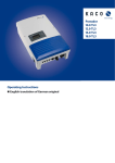
BroadR-Reach – Standard Ethernet BR_SPY User Manual Version 0.1 August 2015 You can download the latest firmware and documentation for the BR_SPY here: http://www.technica-engineering.de/SPY Page 1 of 25 Index 1 2 3 Feature List ..................................................................................................................................... 3 Warranty and Safety Information................................................................................................... 4 Pinning ............................................................................................................................................ 5 3.1 Power connector (top left) ...................................................................................................... 6 3.2 BroadR-Reach connectors ....................................................................................................... 7 3.3 RJ45 Ethernet connectors ....................................................................................................... 8 3.4 SMA Connector........................................................................................................................ 8 4 Status LEDs and Pushbutton ........................................................................................................... 9 5 Configuration Website .................................................................................................................. 10 5.1 Website Home ....................................................................................................................... 10 5.2 System Information Tab ........................................................................................................ 11 5.3 Control Panel Tab .................................................................................................................. 12 5.4 Switch Status Tab .................................................................................................................. 13 5.4.1 Global Configuration: .................................................................................................... 13 5.4.2 Ethernet Port ................................................................................................................. 14 5.4.3 BroadR-Reach Port ........................................................................................................ 15 6 UseCases ....................................................................................................................................... 16 6.1 BroadR-Reach SPY UseCase ................................................................................................... 16 6.2 FrameGenerator UseCase ..................................................................................................... 17 7 Hardware Variants ........................................................................................................................ 18 7.1 BroadR-Reach Analog Filter:.................................................................................................. 18 7.2 Debug connector ................................................................................................................... 18 7.3 Startup Time .......................................................................................................................... 19 8 Application Firmware Update....................................................................................................... 20 9 Frequently Asked Questions – FAQ .............................................................................................. 23 10 Contact.......................................................................................................................................... 24 Page 2 of 25 1 Feature List The Technica Engineering BroadR-Reach SPY samples data Frames directly on the bus without influence of the original network. The data Frames are enhanced with additional information as an exact timestamp and the bus port the data was originally sent on. All data can be recorded on a PC or datalogger for detailed offline analysis. Timestamps are in 0.1 μs resolution and synchronous to all connected lines. Optionally other UseCases (Frame Generator, Fault Injection, Data Manipulation, Trigger Generator, … ) can be upgraded. Features: 12x BroadR-Reach Ports Fullduplex 100 Mbit/s 1x FlexRay Channel A (option for transmission of 2 StartUp & Sync Frames) 5x CAN / CAN-FD Ports 1x LIN, 1x SMA Trigger 4x Gigabit Ethernet Ports for Logging data output 1x Fast Ethernet Port for status output, configuration and webserver access 1x SD Card for configuration and storage of trigger events Stainless steel case Power requirement: Power consumption: Size: Weight: International Protection: Operating Temperature: 12 Volt DC Nominal (7-16 Volt) 10 Watt 147 x 124 x 26mm 0,9 kg IP 2 0 -40 to +80 °Celsius Page 3 of 25 2 Warranty and Safety Information Before operating the device, read this manual thoroughly and retain it for your reference. You can download the latest firmware and documentation for the BR_SPY here: http://www.technica-engineering.de/SPY Use the device only as described in this manual. Use only in dry conditions. Do not apply power to a damaged device. Do not open the device. Otherwise warranty will be lost. This device is designed for engineering purpose only. Special care has to be taken for operation. Do not use this device in a series production car. As this device is likely to be used under rough conditions, warranty is limited to 1 year. Manufacturer liability for damage caused by using the device is excluded. Page 4 of 25 3 Pinning The pinning of the ECU connectors is listed on the label on top of the device. The Tyco Electronics (TE) Nano Micro Quad Lock System (NanoMQS) is used. Name Part Number 20POS NANOMQS REC HSG CODE A 2141404-1 NANOMQS RECEPTACLE TERMINAL 2-1703930-1 Official Crimp Tool: TE CONNECTIVITY CS11K NANO-MQS, 0.13-0.35 SQ.M TE Internal Number: 4-1579014-0 Distributor: Börsig GmbH Siegmund-Loewe-Str. 5 74172 Neckarsulm www.boersig.com Page 5 of 25 3.1 Power connector (top left) Power supply for the device is supplied by Pin 18 (12Volt) and Pin 20 (Ground). Requirements for the BR_SPY itself: 12 Volt DC up to 1 Ampere (typical 600mA) Warning: If you apply a voltage higher than 16 Volt, the device will be damaged! A wakeup-line may be connected on pin 5. The wakeup-line should have the same voltage level as the power supply (12 Volt). A high level on one of these pins wakes up the ECU from sleep mode and keeps it active. Alternatively the “Prevent sleep” checkbox in the control panel of the website can be enabled. The CAN interfaces can be used to communicate with the Microcontroller by CAN and CAN-FD bus. In the default software there is no data transmission specified. This interface may only be used in customer specific software. The LIN interface can be used to communicate with the Microcontroller by LIN bus. In the default software there is no data transmission specified. This interface may only be used in customer specific software. Page 6 of 25 The FlexRay interface can be used to communicate with the Microcontroller by FlexRay bus. In the default software there is no data transmission specified. This interface may only be used in customer specific software. Pin Function 1 3 5 7 9 11 13 15 17 19 GND Reference for Trigger LIN Bus Wake Line CAN D / 5 Minus (Low) CAN D / 5 Plus (High) n.c. CAN B / 4 Minus (Low) CAN B / 4 Plus (High) CAN A / 3 Minus (Low) CAN A / 3 Plus (High) Pin 2 4 6 8 10 12 14 16 18 20 Function Host Trigger Line FlexRay Channel A BP FlexRay Channel A BM CAN E / 1 Plus (High) CAN E / 1 Minus (Low) CAN C / 2 Plus (High) CAN C / 2 Minus (Low) n.c. Battery +12 Volt Input Battery Ground Input 3.2 BroadR-Reach connectors The pins marked with (P) or (M) are used for the BroadR-Reach ports. You have to connect the (P) pin to the (P) pin of the periphery device. You have to connect the (M) pin to the (M) pin of the periphery device. Note: If you swap these two pins the link LED may be lit on the BroadR-Reach slave side, but no data transmission will be possible. Middle Connector Pin Function 1 3 5 7 9 11 13 15 17 19 Pin GND Reference for Trigger n.c. BroadR-Reach Port 3A / 5, P (Positive) BroadR-Reach Port 3A / 5, M (Negative) n.c. BroadR-Reach Port 2A / 4, P (Positive) BroadR-Reach Port 2A / 4, M (Negative) n.c. BroadR-Reach Port 1A / 1, P (Positive) BroadR-Reach Port 1A / 1, M (Negative) Outer Connector Pin Function 1 3 5 7 9 11 13 15 17 19 2 4 6 8 10 12 14 16 18 20 Pin GND Reference for Trigger n.c. BroadR-Reach Port 6A / 9, P (Positive) BroadR-Reach Port 6A / 9, M (Negative) n.c. BroadR-Reach Port 5A / 8, P (Positive) BroadR-Reach Port 5A / 8, M (Negative) n.c. BroadR-Reach Port 4A / 7, P (Positive) BroadR-Reach Port 4A / 7, M (Negative) Page 7 of 25 2 4 6 8 10 12 14 16 18 20 Function FPGA Trigger Line OUT1 n.c. BroadR-Reach Port 3B / 6, P (Positive) BroadR-Reach Port 3B / 6, M (Negative) n.c. BroadR-Reach Port 2B / 3, P (Positive) BroadR-Reach Port 2B / 3, M (Negative) n.c. BroadR-Reach Port 1B / 2, P (Positive) BroadR-Reach Port 1B / 2, M (Negative) Function FPGA Trigger Line IN1 n.c. BroadR-Reach Port 6B / 12, P (Positive) BroadR-Reach Port 6B / 12, M (Negative) n.c. BroadR-Reach Port 5B / 11, P (Positive) BroadR-Reach Port 5B / 11, M (Negative) n.c. BroadR-Reach Port 4B / 10, P (Positive) BroadR-Reach Port 4B / 10, M (Negative) 3.3 RJ45 Ethernet connectors There are for RJ45 Standard Ethernet connectors of the front side for Gigabit Ethernet. There is one RJ45 Standard Ethernet connector of the front side for Fast Ethernet (100 Bit/s) 3.4 SMA Connector There is one shielded SMA Connector for one Trigger Input/Output Line. Page 8 of 25 4 Status LEDs and Pushbutton The BR_SPY has several status LEDs at the front side of the case. The “Host” LED1 can toggle at three different speeds: Slow toggle (approx. 0.5 sec) during normal operation to show that the microcontroller is running in normal mode. Fast toggle (approx. 0.1 sec) when the microcontroller is in bootloader mode. The bootloader mode is used for firmware update only (see below in this manual). You cannot access the website when the device is in bootloader mode. When the device is in Bootloader-Update Mode the LED toggles with moderate frequency (approx. 0.25 sec). The “Host” LED2 should be normally off. If it toggled at high speed (approx. 0.1 sec) an error has been detected by the Host. The “FPGA” LED1 can toggle at two different speeds: Slow toggle (approx. 0.5 sec) during normal operation to show that the FPGA is running in normal mode. Fast toggle (approx. 0.1 sec) : TBD The “FPGA” LED2 should be normally off. If it toggled at high speed (approx. 0.1 sec) an error has been detected by the FPGA. The 12 port status LEDs 1A to B6 monitor the link status of the corresponding port. The LEDs are lit when there is BroadR-Reach link detected. Note: There is an issue when P/N of the bus are swapped. The LED may be on in this case on BroadRReach slave side, but there will be no data transmission possible. The built-in LEDs in RJ45 connector shows the status of the gigabit ports. The left (orange LED) is lit by a link-up. The right (yellow) will blink on data traffic. The Rotary DIP Switch has four modes: 1: TBD 2: TBD 3: TBD 4: TBD Page 9 of 25 5 Configuration Website You can access the configuration website with a standard web browser. Note: Firefox is recommended, Chrome is not recommended. Connect your PC to the “Host” RJ45 connector. The default IP address of the device is 192.168.0.49 and subnet mask 255.255.255.0 If IP address has been changed, you can reset it to default as described in chapter 3 of this manual. For example set the configuration PC to IP address 192.168.0.100 and subnet mask to 255.255.255.0 5.1 Page 10 of 25 Website Home With the first access to the website you will get the home screen. Please select one of the tabs for further configuration. 5.2 System Information Tab Page 11 of 25 On the tab „System Information“ some status information about the device is displayed. You can check the version number of the application firmware and the bootloader or the unique MAC adress of the device. The version number registers of the switch and phy chips are displayed for information only. The MAC adress should be the same as on the label on the bottom of the device. You can change the IP adress of the host microcontroller (Webserver) here. If you want to use multiple devices in one network, you have to configure a unique IP adress for each device here. Note: If someone has changed the IP address you can reset it to default as described in chapter 3 of this manual. 5.3 Control Panel Tab On the „Control Panel“ tab you can soft-reset (restart) the system. Also you can import or export the configuration settings of the device to a file (*.bin) on a computer connected to the RJ45 Port. You have to restart the device for usage of the new configuration. You can reset the configuration settings to default. All the configuration stored will be revert to its defaults values. If you do not want to use a WakeUp line, you can enable the “Prevent sleep” checkbox (default). This will keep the device running without entering the sleep mode. Page 12 of 25 5.4 Switch Status Tab The main configuration of the switch is done in the „Switch Status“ tab. Here you can configure details about each port and get some status information about the ports and switch states. On the left side of the page you can see an overview of all available ports. A blue bar at the side of a port label indicates an active link. 5.4.1 Global Configuration: When you click on „Switch Status“ tab and no port or switch is still selected, Global configuration will appear. Page 13 of 25 . 5.4.2 Ethernet Port TBD Detected speed: Show result of link negotiation. Speed and half/full duplex. Page 14 of 25 5.4.3 BroadR-Reach Port Besides the common fields to all ports, BroadR-Reach ports allows the user to: BroadR-Reach mode: On each BroadR-Reach link there has to be one master and one slave device. Please set the “BroadR-Reach mode” to the opposite of what the device is set you have connected to this port. Output level: The “Output Level” is the amplitude level of the BroadR-Reach signal. You can set Full level (Fullout = default) or half amplitude. Note: Both devices of one BroadR-Reach link have to use the same level. Otherwise you will get an instable link. FullOut Level is always recommended. For BroadR-Reach Ports it is possible to set a BroadR-Reach Physical Layer Test Mode. There are five test modes defined in the BoradR-Reach Specification to check the compliance of a port. Warning: When a test mode has been selected there is no communication possible for this port. Note: For compliance testing an oscilloscope with special test software is necessary. Page 15 of 25 6 UseCases 6.1 BroadR-Reach SPY UseCase The traffic of two BroadR-Reach ECUs is forwarded through the BR_SPY with a constant delay of only 2us. The delay is independent of the frame size of the Ethernet packets. There is no time jitter on the delay. The used bandwidth has no influence on the delay. The traffic of two pairs of BroadR-Reach (so a total of four ports) of forwarded to one Gigabit Port. The PC/Datalogger is not able to send data. The RJ45 Ports are output only. Each RJ45 Port outputs only one 100 Mbit Stream of one of the ECUs. This setup (Four on One) is implemented three times in one BR_SPY. So a total of 12 BroadR-Reach Ports and 3 Gigabit Ports are used for this. Page 16 of 25 6.2 FrameGenerator UseCase The Frames are transmitted on Port 1 - 12. The Frame Format is fixed. The StreamID 1..12 is Portnumber Example with mixed frame sizes: Page 17 of 25 7 Hardware Variants 7.1 BroadR-Reach Analog Filter All filter versions are compatible with each other. The Broadcom BCM89811 PHY with integrated low pas filter is used. For EMC and Bus termination the following filter is mounted on BrodR-Reach lines: 7.2 Debug connector There is a debug connector on the front side of the case near the SD card slot. This small connector is only for customer service purpose. Warning: Do not connect anything to this port. Page 18 of 25 7.3 Startup Time TBD Note: On the RJ45 gigabit ports the Linkup time is about 3 to 4 seconds. This is because of IEEE Auto Negotiation which has to be done in gigabit mode. Page 19 of 25 8 Application Firmware Update You can download the latest firmware and documentation for the BR_SPY here: http://www.technica-engineering.de/SPY The application firmware of the device may be updated by the following process: Note: If you update the application the bootloader should also be updated to the latest version. Warning: Not following this instruction may cause erroneous states of the device. You will have to send it back to Technica Engineering for repair. Technica Engineering may charge support fees for this service. Note: You need to have administration privileges on a Windows PC to be able to do the firmware update on the BR_SPY Note: Please use the script “Update all.bat” supplied with the firmware binary filed for updating all components of the device. 1. Power up the device by a stable 12 Volt DC power supply. Do not switch off the power supply during the update process. 2. It is recommended to connect the Wake-up line (Pin 8 of the black MQS connector) to 12 Volt of the same power supply to make sure the ECU is awake during update. 3. Connect a Windows PC with a RJ45 cable directly to the left RJ45 Port of the MediaGateway and make sure there is a link. Do not connect a switch in between. 4. Disconnect all other Ethernet, CAN, FlexRay, LIN and BroadR-Reach links from the BR_SPY. 5. Disable the Firewall of the Windows PC. Set the network device of the PC to the same subnet as the BR_SPY. (For example 192.168.0.100 and 255.255.0.0) 6. Check that your firmware package you received from Technica Engineering contains the following files: redtool.exe microcontroller.crc.srec redboot.srec spy.srec You will need to have java installed on your PC. 7. Check that the “Host” LED toggles slowly (so the device is running in application mode). 8. Check that you can access the website at 192.168.0.49 (or whatever the IP address of the BR_SPY is configured for). Page 20 of 25 9. Open a DOS-Box and execute the following command to enter bootloader mode: redtool.exe -t 192.168.0.49 -e Option –t specifies the IP Address of the BR_SPY. Option –e restarts the BR_SPY and starts it in bootloader mode. Note: The Host LED1 is blinking fast when in bootloader mode. 10. In the DOS-Box execute the following command: redtool.exe -t 192.168.0.49 -f microcontroller.crc.srec -r Option –t specifies the IP Address of the BR_SPY. Option –f specifies the new firmware file. Option –r activates the application mode after successful update. Note: during the update process the Host LED1 will stop to blink. This is a normal condition. Do not reset the device! The update process will last about one minute. When the update is finished the Host LED will toggle slowly again. 11. You can re-activate your Windows firewall after successful update. . . . -------------------------------------------------------C:\_Altera_SPY2\Calypso_FW\BRSPY-Release-v1.1 Connect new device. Make sure firewall is disabled. -------------------------------------------------------Drücken Sie eine beliebige Taste . . . Process started..... ======================================================== Old Bootloader Version: ======================================================== Connecting to 192.168.0.49:9000 (1). Connected Sending ^C Non-certified release, version 2.0 - built 09:57:49, Jul 28 2015 Connecting to 192.168.0.49:9000 (1). Connected Sending ^C Testing TFTP server tftpServer ready. Port: 69 tftpServer: 127.0.0.1 requested file redboot-updater.srec [****************************************] TFTP transfer finished TFTP server ok Loading test file... tftpServer: 192.168.0.49 requested file redboot-updater.srec [***********************TFTP transfer finished Test File loaded successfully Updating application Erasing flash... Flash erased Loading file... tftpServer: 192.168.0.49 requested file redboot-updater.srec [****************************************] TFTP transfer finished File loaded successfully Run application... Connecting to 192.168.0.49:9000 (1). Page 21 of 25 Connected Sending ^C Testing TFTP server tftpServer ready. Port: 69 tftpServer: 127.0.0.1 requested file redboot.srec [****************************************] TFTP transfer finished TFTP server ok Loading test file... tftpServer: 192.168.0.49 requested file redboot.srec [************************TFTP transfer finished Test File loaded successfully Updating redboot Erasing flash... Flash erased Loading file... tftpServer: 192.168.0.49 requested file redboot.srec [****************************************] TFTP transfer finished File loaded successfully Run application... ++++++++++++++++++++++++++++++++++++++++++++++++++++++++ NEW Bootloader Version: ++++++++++++++++++++++++++++++++++++++++++++++++++++++++ Connecting to 192.168.0.49:9000 (1). Connected Sending ^C Non-certified release, version 2.0 - built 17:04:51, Aug 19 2015 Connecting to 192.168.0.49:9000 (1). Connected Sending ^C Testing TFTP server tftpServer ready. Port: 69 tftpServer: 127.0.0.1 requested file microcontroller.crc.srec [****************************************] TFTP server ok Loading test file... TFTP transfer finished tftpServer: 192.168.0.49 requested file microcontroller.crc.srec [***TFTP transfer finished ] Test File loaded successfully Updating application Erasing flash... Flash erased Loading file... tftpServer: 192.168.0.49 requested file microcontroller.crc.srec [****************************************] TFTP transfer finished File loaded successfully Connecting to 192.168.0.49:9000 (1). Connected Sending ^C Testing TFTP server tftpServer ready. Port: 69 tftpServer: 127.0.0.1 requested file spy.srec [****************************************] TFTP server ok Updating FPGA Erasing flash... TFTP transfer finished Flash erased Loading file... tftpServer: 192.168.0.49 requested file spy.srec [****************************************] TFTP transfer finished File loaded successfully Connecting to 192.168.0.49:9000 (1). Connected Sending ^C Run application at address 0x1006b40... Drücken Sieeine beliebige Taste . . . Page 22 of 25 9 Frequently Asked Questions – FAQ Q: What is the delay time for Ethernet packets through the BR_SPY? A: The propagation delay of the BR_SPY is constant 2us between two BroadR-Reach Ports in SPY mode. Q: Is AVB supported? A: As the delay through the BR_SPY between two BroadR-Reach ports in only 2 us and constant the BR_SPY will not influence a AVB time synchronous network negatively. Q: What to do to get CAN, FlexRay and LIN supported? A: In the standard firmware edition these interfaces are not supported. Please contact the sales of Technica Engineering GmbH to get information about advanced software features. Q: After a firmware update the host LED is still blinking fast. What to do? A: The firmware update failed and the host is still in bootloader mode. Please restart the device and try to update the application again as described in this manual. Q: I have problems with the website user interface. A: The website is tested with Firefox and Internet Explorer. Firefox is preferred. Chome is not supported. Page 23 of 25 10 Contact In the „Contact Tab“ information is displayed how to contact us if you need service. If you have any questions regarding this product please feel free to contact us: Technica Engineering GmbH Olschewskibogen 18 80935 München Germany Fax: +49-89-34290265 [email protected] www.technica-engineering.de Page 24 of 25