1
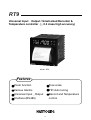
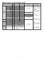
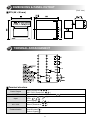
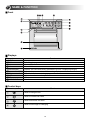
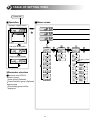
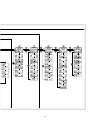
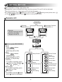
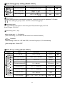
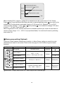
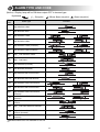
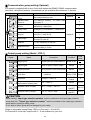
#1381-3, Juan-dong, Nam-gu, Incheon, Korea
TEL:(82-32) 876-4697 FAX:(82-32) 876-4696
http://www.hynux.com E-mail: [email protected]
MA01E50110
Recorder & Temperature Controller
RT9
INSTRUCTION MANUAL
Thank you for the purchase of HANYOUNG product.
Please read this manual carefully.
Contents
1. SAFETY INFORMATION
4
2. INSTRUCTION
6
3. ORDERING INFORMATION
6
4. SPECIFICATION
7
5. DIMENSIONS & PANEL CUTOUT
11
6. TERMINAL ARRANGEMENT
11
7 NAME & FUNCTION
12
8. TABLE OF SETTING ITEMS
13
10. SETTING METHOD
15
20. GROUP SETTING
16
21. FUNCTION
23
2
RT9
Universal Input Output / Small-sized Recorder &
Temperature controller ( 0.3 class high accuracy)
Model : RT9
Features
Zoom function
Free scale
Various Alarms
PID Auto tuning
Universal Input
Record and Temperature
Output
control
Interface (RS485)
3
1
SAFETY INFORMATION
Before using, please read this (SAFETY INFORMATION)
It is most important that the instructions in this manual are followed when using this instrument.
Please keep this manual for future reference.
Precautions are classified as WARNING and CAUTION.
WARNING
There is a possibility of death or heavy injury when handling in wrong way.
CAUTION
There is a possibility of injury or physical damage when handling in wrong way.
WARNING
1. Caution on wiring
Use an external protection circuit if a fault in the control loop could possibly lead to a serious
problem.
This instrument does not have a switch for power and a fuse, so please install them if reguired.
(Fuse rating 250V, 0.5A)
2. Power supply
Use a rated voltage to prevent damage or trouble.
To avoid electrical shock or damage, do not turn ON the power until the wiring is completed.
3. Prohibit use in gas atmosphere
Do not use it at a place exposed to combustible or explosive gas.
4. Handling of unit
To avoid malfunction, electrical shock or fire, this unit must not be disassembled or repaired.
Do not touch the terminals to avoid electrical shock or malfunction.
5. Caution on maintenance
Turn OFF the power before mounting or removing the instrument.
To ensure continuous and safe operation of the instrument, periodical maintenance is
recommended. Some parts are limited in life.
The warranty period is 1 year only if using in the correct way.
CAUTION
1. Caution on handling
Do not install the instrument under any of the following condltions.
The ambient temperature exceeds 0 ~ 50
The ambient humidity exceeds 20 ~ 90%RH.
A place where temperature changes suddenly or icing occurs.
A place exposed to corrosive gas or combustible gas.
Vibration or shock is likely to be transmitted to the instrument.
A place exposed to water, oil, chemicals, steam, sunlight.
A place exposed to much dust, salt or iron.
A place with much inductive disturbance, static electricity, magnetism noise.
A place where heat such as radiant heat stays.
4
2. Installation
Attach the brackets (2 units) on the fixed halls and tighten with a screwdriver.
Fixing torque is about 14.7N. cm (1.5kg.cm).
(Care should be taken not to tighten forcedly.)
Indoor use.
Altitude up to 2000m use.
Mains supply voltage fluctuations not to exceed 10 of the normal voltage.
Installation Categories
Pollution degree 2
3. Caution on terminal connections
Use a compensating cable with thermocouple.
For R.T.D input use a cable which is a small lead wire resistance and without resistance
difference to 3wires.
To avoid inductive noise to input wires separate from the power and output wires.
Keep input wires away from output wires and use shielded wires to earth.
If the wiring has noise, use the following step: connect a surge absorber to the conductor coil
side if the conductors are connected to the load output, such as the relay contact output.
Use an insulating transformer with a noise filter when the power suppy has much noise.
Noise filter should be mounted on a panel which has been earthed and the wiring between the
noise filter output and the instrument power terminals should be shorten.
It is effective to use a twisted cable for power supply against noise.
The heater power supply and the instrument power supply should be connected using the
same power suppy when a heater break alarm.
Time for preparation of contact output is required at power ON. When the output signal is used
for an extenal interlock circuit, connect a delay relay.
4. For load circuit connection
Use an extra relay when the frequency of operation is rather high. In this case, SSR output type
is Recommended.
Electromagnetic switch : Proportional cycle time is Min. 30 sec
SSR : Proportional cycle time is Min. 2 sec
Contact output life : Mechanical : Min. 10 million times (no load)
Electrical : Min. 100 thousand times (rated load)
SSR drive pulse voltage, DC 4~20mA are not insulated with internal circuit.
Use non-grounded sensor to R.T.D and thermocouple.
5. Caution on key operation / trouble
If alarm function is not set correctly, alarm output can not operate correctly a trouble.
Be sure to check the alarm operation.
If the input cable is disconnected, the display shows “
”.
When replacing the sensor, please turn OFF the power supply.
6. Other
Do not use organic solvents such as alcohol, benzine when cleaning. (Use neutral detergent)
5
2
INSTRUCTION
This instrument has process-value (PV) and set-value (SV) each 4 digits with 7 segment FND.
This instrument is divided either Recorder and Recorder with Controller.
Function and feature
: Group P.I.D, Universal-input (19 types), Universal-output (Relay, SSR, SCR), Auto-tuning 2
types (standard type, low PV type), Communication (RS485), 20 types of alarm, Sampling cycle
250ms, 0.3 of FS high accuracy. And there are Zoom function, Graphic or Text printing
selectable function, List printing function, Feed function, Free scale function. RT9 is the smallest
Recorder with controller.
3
ORDERING INFORMATION
Model
RT9 -
Description
96 96 mm
Recorder
Recorder & Temperature Controller
Suffix code
0
1
0
1
Others
None
Alarm 1
Alarm 1, 2
RS485
RS485 / Alarm 1
RS485 / Alarm 1, Alarm 2
0
1
2
3
4
5
Control output
Recorder &
Temperature Controller
RT9 - 1
Output code
Control Output
0
1
2
3
Relay (ON / OFF control)
SSR
SCR (4 ~ 20 mA DC)
Relay (P.I.D control)
6
4
SPECIFICATION
INPUT
Input
Sampling time
Input resolution
Input impedance
Lead wire tolerable
resistance
Input tolerable voltage
Noise removal rate
Standard
Standard junction temp.
compensation tolerance
Burn-out
Accuracy
Input range
Thermocouple : K, J, E, T, R, S, B, L, N, U, WRe 5-26, PLR.T.D : Pt 100 , KPt 100
Direct voltage: 1 ~ 5 V, -10 ~ 20 mV, 0 ~ 100 mV (Free scale type)
250 mS
Below decimal point of measurement range
T/C and mV input : 1
min., V DC : 1
R.T.D : 10
max. / wire
10 V (T/C, R.T.D, Voltage : mV DC), 20 V (Voltage : V DC)
NMRR(normal mode) : 40 dB min.
CMRR(common mode) : 120 dB min. (50/60 Hz 1 %)
T/C, R.T.D: KS, IEC, DIN
1.5
(15 ~ 35
),
2.0
(0 ~ 50
)
T/C : OFF, Up/Down selectable
R.T.D : Up scale (Detection current : 50 mA)
0.3 % (Full scale)
Refer to “Input signal and Measurement range”
T/C and R.T.D are changeable within range of input signal and measurement
range.
Voltage: min. voltage and max. voltage are available within range of
measurement. Scaling available.
OUTPUT
CONTROL OUTPUT
Relay
contact output
SSR drive
voltage output
Current output
(4 ~ 20 mA DC)
Contact capacity : 240 V AC 3 A, 30 V DC 3 A (resistive load), Contact : 1 C
Output operation : P.I.D control, ON/OFF
Proportional cycle : 1 ~ 1,000 sec.
Output limit : 0.0 ~ 100.0 % range, higher limit(OH) or lower limit(OL)
selectable (valid when AT)
ON/OFF hysteresis : 0 ~ 100 %(Full scale)
Time resolution : 0.1 % or 10 mS
ON voltage : 24 V DC min.(resistive load 600
min., 30 mA limit when short)
OFF voltage : 0.1 V DC max.
Proportional cycle : 1 ~ 1,000 sec.
Output operation : P.I.D control
Output limit : 0.0 ~ 100.0 % range, higher limit(OH) or lower limit(OL)
selectable (valid when AT)
Time resolution : 0.1 % or 10 mS
Current output range : 4 ~ 20 mA DC, Resistive load : 600
max.
Accuracy : 0.5 % of full scale (4 ~ 20 mA range), Resolution : Approx. 3,000
Output ripple : 0.3 %(P-P) of max. scale (150 Hz)
Sampling time : 250 mS
Output operation : P.I.D control
Output limit : -5.0 ~ 105.0 % range, higher limit(OH) or lower limit(OL)
selectable (valid when AT)
7
ALARM
Relay
contact output
Contact capacity : 240 V AC 1 A, 30 V DC 1 A(resistive load)
Contact: 1 a
Output points: 2 Points (AL1,AL2)
FUNCTION
Measurement input
Control
Alarm output
Record
Input correction (Bias): -100.0 ~ 100.0 % for instrument range
Scaling : According to SH, SL of measurement range
Filter : OFF, 1 ~ 120 sec.
3 settings (SV1, SV2 and SV3) and P.I.D setting each
Auto tuning : According to set value (Standard type, Low PV type)
Proportional Band : 0.1 ~ 999.9 % (Max. range)
Integral Time : OFF, 1 ~ 6000 sec.
Derivative Time : OFF, 1 ~ 6000 sec.
ON/OFF control : By selecting output code (OT) “ 0 ”
P.I.D selection : Zone PID/Auto 1,2,3, selectable
Manual Reset : -5.0 ~ 105.0 % of output (valid when I=OFF)
Direct / Reverse action : Changeable by parameter
Preset output limit : -5.0 ~ 105.0 % of output value
ON/OFF hysteresis (HYS) : 0.0 ~ 100.0% of instrument range (valid when
ON/OFF control)
A.R.W(Anti Reset Wind-up) : AUTO, 50.0 ~ 200.0 %
Fuzzy : selection ON or OFF by parameter
Ramp function
Set point : 2 Points
Multi-alarm : High/Low process alarm, High/Low deviation alarm, Hold function
of alarm, Heater break alarm (H.B.A)
Setting range : Process alarm
0 ~ 100 % of instrument range
Deviation alarm
-100 ~ 100 % of instrument range
Measuring point : 1
Response time : According to chart speed
Record type : Thermal line, 203 dpi(8.0 dots/mm) 384 dots / 1 line
Record speed : 24 mm/h ~ 900 mm/h
Paper : Width 57.5 mm, Length 16 m
OPERATING ENVIRONMENT
Continuous vibration (5~14Hz): Forward width 1.2 mm max.
(4~150Hz): 4.9
(0.5 G) max.
Installation environment Vibration : 14.7
, 15 sec. max. (each 3 direction)
Shock : 147
(15 G), 11 msec max. (6 direction each 3 times)
Panel cutout: Refer to page 11
Ambient temperature : 0 ~ 50
Normal operation
Ambient humidity : 35 ~ 85 % RH (no condensation)
condition
Influence of magnetic : 400 AT/m max.
Warm-up time: 30 min. min.
T/C, Voltage input : 1 V/ or 0.01 %/ of max. range
Influence of ambient
R.T.D input : 0.05 / max.
temperature
Analog output : 0.05 %/ max. (continuous output)
8
STORAGE CONDITION
Storage temperature
Storage humidity
Shock
-25 ~ 70
5 ~ 95 % RH (no condensation)
1 m max. in packing condition
STRUCTURE
MODEL
RT9
External Dimension
96(W) 96(H) 100(D) mm
Weight
530 g
Material
Plastic case(ABS)
POWER SUPPLY
Power supply
Frequency
Power consumption
Insulation resistance
Dielectric strength
100 ~ 240 V AC (90 ~ 264 V AC)
50/60 Hz
6.0 W max., 10 VA max.
Between primary terminal and secondary terminal : 500 V DC, 20
min.
Between primary terminal and ground : 500 V DC, 20
min.
Between ground and secondary terminal : 500 V DC, 20
min.
Between primary terminal and secondary terminal : 2,300V AC 50/60 Hz for 1 min.
Between primary terminal and ground : 2,300 V AC 50/60 Hz for 1 min.
Between F G and secondary terminal : 1,500 V AC 50/60 Hz for 1 min.
SAFETY AND EMC STANDARD
Safety standard
EMC standard
Under process
Under process
INTERFACE
Standard
Communication address
Communication method
Synchronization
Communication sequence
Communication distance
Communication speed
Start bit
Data bit
Parity bit
Stop bit
Communication protocol
Response time
EIA RS485
Max. 31 (1 ~ 99 setting available)
2 wire half duplex or 4 wire half duplex
Start-stop synchronous mode
None
1.2 Km max.
600, 1200, 2400, 4800, 9600 BPS (Speed is changeable by parameter)
1 BIT
7 or 8 BIT
None, even numbers, odd numbers
1 or 2 BIT
PC LINK WITHOUT SUM(0), PC LINK WITH SUM(1)
Reception treatment time + (Response time
10 mS)
9
INPUT SIGNAL and MEASUREMENT RANGE
Input
code
K
1
2
K
2
2
J
3
2
E
4
2
T
5
2
R
6
2
B
7
1
S
8
L
9
2
N
10
U
11
2
W
12
13
Platinel
20
KSPt 100 3
21
3
Pt 100
30
1 ~ 5 V DC
31
0 ~ 10 V DC
-10 ~ 20 mV DC 32
0 ~ 100 mV DC 33
Input type (Input signal)
Thermo
-couple
(T.C)
R.T.D
Direct
voltage
(V DC /
mV DC)
Direct
4 ~ 20 mA DC
Current
Range ( )
Range(
)
-300~2500
-200~1370
0~2300
-199.9~999.9
-199.9~999.9 -300~2300
-199.9~999.9 -300~1800
-199.9~400.0 -300~750
32~3100
0~1700
32~3300
0~1800
32~3100
0~1700
-199.9~900.0 -300~1300
-300~2400
-200~1300
-199.9~400.0 -300~750
32~4200
0~2300
32~2500
0~1390
-199.9~500.0 -199.9~999.9
-199.9~640.0 -300~1180
1~5V
0 ~ 10 V DC
-10 ~ 20 mV
0 ~ 100 mV
When using current
input, use the resistor
30
250
0.1 % on input
terminal.
10
Accuracy
0.3 % of F.S
1 digit
Remarks
F.S is maxium
value ~ minimum
value of each
RANGE.
Digit is minimum
value of display
0.3 % of F.S
1 digit
1
0.3 % of F.S 1 digit 0 ~ 400
: 10 %
1.0 % of F.S 1 digit of F.S 1 digit
0.3 % of F.S
1 digit
2
0
and below :
1.0 % of F.S 1 digit
0.3 % of F.S
1 digit
3
-150.0~150.0 range :
1.0 % of F.S 1
digit
20
21
KPt 100
DPt 100
5
DIMENSIONS & PANEL CUTOUT
RT9 (96
6
(Unit : mm)
96 mm)
TERMINAL ARRANGEMENT
RS 485
Terminal structure
Control Output
POWER
Input
AL1 / AL2
Communication
Relay(Terminal no.
)
SSR / SCR (Termina no.
)
100 - 240 V AC 50/60 Hz. (Termina no.
Termocouple:
+,
R.T.D:
A,
B
Direct Voltage :
+,
Alarm1 (Terminal no.
)
Alarm2 (Terminal no.
)
Sending data ( )
Receiving data ( )
Earth for signal( )
11
)
7
NAME & FUNCTION
Front
Displays
Name
P.END
RUN
AL1
AL2
Set-value(SV)
Process-value(PV)
AT
OUT
RT9
HANYOUNG
Functions
No paper
Recording in progress
Alarm 1 ON
Alarm 2 ON
Displays set value and various parameters.(RT9-0 : Displays input type)
Displays the process value. When setting, displays various modes.
Flickers when the auto tuning operates.
Lights when the control output is ON.
Model name
Manufacturer
Control keys
Functions
Key
Used to change mode.
Used to increase set-value.
Used to decrease set-value.
Used to select digit for changing.
12
8
TABLE OF SETTING ITEMS
Power ON
Operation
Menu screen
Operation display status.
3 sec.
Set value changeable
Group
Control
Group
Autotuning
Group P.I.D
Output volume display
Set a number
Parameter structure
Recorder only (RT9-0):
Control group
Alarm group (Optional)
Communication group (Optional)
Input group
Time setting group will be
displayed.
13
Group
Alarm
Group
Communication
Group
Output
14
Group
Input
Group
Time setting
9
SETTING METHOD
After completion of wiring, apply power ON.
Management version indicated as below and then present PV and SV will be indicated.
(Record exclusiue use : Input type and PV will be indicated)
For setting a level, press
button for 3 sec. to enter
setting mode.(Initial value :
In the
condition, press
button to enter group control.
Parameter shift
Power ON
Recorder& Controller
(Model:RT9-1)
Recorder
(Model:RT9-0)
Recorder
: Displays input type and PV
Recorder & controller
: Displays SV and PV
For 3 sec
How to operate RECORDER
RUN
Press
buttons
simultaneously
(RUN lamp will be ON)
Stop
Press
buttons
simultaneously
(RUN lamp will be OFF)
Graphic or Text printing
selection
In condition of printing, press
button for 3 sec.(Graphic
Text
Graphic ...)
List printing
In condition of printing, press
button for 3 sec.
Feed paper
In condition of press
button,
press
button to feed paper.
Group Control
Group Control
Group
Auto tuning
Group PID
Group Alarm
Group Alarm
Group
Communication
Group
Communication
Group Output
15
Group Input
Group Input
Group
Time setting
Group
Time setting
)
10
GROUP SETTING
Display level setting
Signal
Display Name
Description
Condition
Divide display levels into
Always
Display level setting
3 stages (1~3)
This controller has 3 different levels of setting, thereby restricting operator access if so desired.
Initial
3
Control group setting
Signal
Name
Description
Condition
Initial
Control group display
Set a control mode
Always
Zone selection 1
OFF / ON
Except ON/OFF
OFF
Fuzzy function
OFF / ON
Always
OFF
Initial increasing temperature
OFF / EUS (0~100 %)
Always
OFF
Initial decreasing temperature OFF / EUS (0~100 %)
Always
OFF
Time unit
HOUR / MIN
Always
HOUR
Set speed of transmission
24 ~ 900 mm/hour
Always
60
Zoom
OFF / ON
Always
OFF
16
Auto tuning group setting (Model: RT9-1)
Signal
Name
Description
Condition
Auto tuning group
Indicates Auto-turing
RT9-1
Auto tuning type
/
ABS
STD
ABS
OFF
Auto tuning start
OFF / 1~3 /
Initial
Auto-tuning
The Auto tuning function automatically measures, computes and set the optimum P.I.D value.
Note After setting all group, select AUTO in Auto tuning group.
Auto-tuning type
This controller has two types of auto tuning as STD (standard type) and Low.
(Low PV type : SV-10%)
Auto-tuning start
stop
Auto tuning start : 1~ 3 selection
(After auto tuning , P.I.D value will be stored at a selected number)
Selection
When setting a value on 1.RP and 2.RP, it is stored in group 1,2,3 automatically
Auto tuning stop : Select OFF
P.I.D Group setting (Model: RT9-1)
Signal
Name
Description
Condition
P.I.D group
Set P.I.D mode
RT9-1
Anti Reset Wind-up
Auto / 50.0 ~ 200.0 %
Except
ON/OFF
Auto
P.I.D group selection
0/1~3
Always
0
n.Proportional band (P)
0.1 ~ 999.9 %
P.I.D group
5.0 %
n.Integral time (I)
OFF / 1 ~ 6000 sec
P.I.D group
240 sec
n.Derivative time (D)
OFF / 1 ~ 6000 sec
P.I.D group
60 sec
n.Manual reset
-5.0 ~ 105.0 %
Integral time
: OFF
50.0 %
n.Zone position
EU(0) < 1.RP < 2.RP < EU(100.0 %)
ZONE : ON
EU
(100.0 %)
17
Initial
Maximum Range (Eu:100%)
Zone 3
Set point of Zone 2 (2,RP)
Zone 2
Set point of Zone 1 (1,RP)
Zone 1
Time
Minimum (Eu: 0%)
When checking P.I.D. values or setting SV in manual mode, this can be done in P.I.D. Group.
Press
key to get Anti Reset Wind value by auto or manual and then press
once more to be
indicated P.I.D mode which is selectable 3 types of P.I.D group (0~3). Example, “0” is no P.I.D
mode and after seleting “1” using
or
and pressing
, it is available to change P.I.D value
in zone “1”. (“2” and “3” are same as “1”)
When integral time is OFF, manual reset mode is indicated and then you could set reset value to
remove off set. (range: -5 % ~ 105.0 % of proportional band). You could set 3 zones by selecting
zone mode ON.
Alarm group setting (Optional)
There are 2 alarm outputs available per controller. In Alarm Group, setting are made for mode,
dead band and value of each alarm. Refer to the next page for the 20 different types of alarm
functions.
Signal
Name
Alarm group
Type of Alarm 1
Type of Alarm 2
Description
Condition
Set alarm mode
Optional
Initial value
1
OFF / 1 ~ 22
Refer to Alarm type and code
Always
EUS ( 0.0 ~ 100.0 % )
Always
EUS(0.5%)
PV alarm, Deviation alarm:
EU ( -100.0 ~ 100.0 % )
Always
EU(100.0%)
EU(0.0%)
2
Dead band of Alarm 1
Dead band of Alarm 2
Set value of Alarm 1
Set value of Alarm 2
Reference : Display lamp will be OFF when output ON in inverted type.
18
ALARM TYPE AND CODE
(Notice) : Display lamp will be ON when output OFF in inverted type.
Hysteresis
Code
NO.
(
: Set point ,
Alarm type
1
High absolute value
2
Low absolute value
3
High deviation value
4
Low deviation value
5
High deviation value (inverted)
6
Low deviation value (inverted)
7
High
Low deviation value
8
High
Low band
9
High absolute (inverted)
10
Low absolute (inverted)
11
High absolute with hold function
12
Low absolute with hold function
13
High deviation with hold function
14
Low deviation with hold function
15
16
17
18
19
20
: Minus Alarm set point ,
Function
High deviation with hold function
(inverted)
Low deviation with hold function
(inverted)
High Low deviation with hold
function
High
Low band with hold function
High absolute value with hold
function (inverted)
Low absolute value with hold function
(inverted)
Marked alarms are not available in RT9-0
19
: Alarm set point )
Communication group setting (Optional)
RT9 series is equipped with 4 wire /2 wire half-duplex the RS485 / RS422 communication
interfaces. Using the interfaces, communications are available with maximum 31 devices.
Signal
Name
Communication
group
RS485/RS422
Protocol
Communication rate
(B.P.S)
Description
Set communication mode
Condition
Initial value
Optional
PC.LINK(Set value:0) / PC.LINK SUM
(Set value:1)
600(SV:0) / 1200(SV:1) / 2400(SV:2)
4800(SV:3) / 9600(SV:4)
0
4
Parity check
NONE(SV:0) / EVEN(SV:1) / ODD(SV:2)
Stop bit
1bit (SV:1) / 2bit (SV:2)
Data length
7bit (SV:7) / 8bit (SV:8)
(Except PC LINK :8)
8
Address
1 ~ 99, maximum 31 devices
1
Response time
0 ~ 10. response time = (handling time +
response time) X 10 ms
0
1
Optional
1
Output group setting (Model : RT9-1)
Signal
Name
Description
Condition
Initial
value
Output group
Output type and mode selection
Output signal
Refor to type of control output
Always
3
Output operation
REV: Reverse DIR: Direct action
Always
REV
Cycle time
1 ~ 1000 sec
Relay / SSR
30 sec
Hysteresis
EUS(0.0 ~ 100.0 %)
ON/OFF
Control
0
Always
0.0 %
Output volume when input
-5.0 ~ 105.0 %
disconnection Output (Out)
Maximum value of output
OL-L + 1 Digit ~ 105.0 %
Minimum value of output
-0.5 % ~ OL-H-1 Digit
Model:RT9-1
Except
ON/OFF
Except
ON/OFF
100.0 %
0.0 %
CAUTION
When setting, Input type selection number must be selected in the input type selection
mode and also Output type selection number must be selected in the output type selection
mode before moving to other mode.
If not, data of other group will be changed to prior value.
Output is selectable among Relay, SSR and Current(4 ~ 20 mA DC).
For Recorder & Controller, output code 0 ~ 3 are available for your use.
20
Input group setting
Signal
Name
Input group
Description
Condition
Input type and mode selection
Initial value
Always
Input signal selection Refer to input signal and range
Always
Selection
NO.1
High limit
Always
1370
Always
-200
Low limit
Refer to input signal and range
( Notice : FR-H > FR-L )
Decimal point
(on voltage input)
Maximum on scale
(on voltage input)
Minimum on scale
(on voltage input)
Thermocouple or R.T.D : Not available On voltage
input (mV,V)
DC Voltage : 0~3
PV filter
OFF/1~120sec
Always
OFF
PV bias
EUS (-100.0~100.0%)
Always
EUS(0.0 %)
Burn-out
OFF / UP / DOWN
Always
UP
-1999~9999
Notice : SL-H
SL-L
Deimal point : according to DP-P
On voltage
input (mV,V)
1
100.0
0.0
CAUTION
When setting, Input type selection number must be selected in the input type selection
mode and also Output type selection number must be selected in the output type selection
mode before moving to other mode.
If not, data of other group will be changed to prior value.
Input type selection
After power ON and when PV is indicating, press
key for 3 sec to be displayed
at
PV and 3 at SV. (If it is not indicated 3, set again in the level setting mode)
Control group is indicated when press
key once more. At the time, input group is indicated
when press
key and then Input type and range selection is shown at SV when press
.
At this time the input and range is selected by
or
key. Press
key to confirm
Maximum and Minimum range
Press
key to set Maximum and Minimum range using
or
key. Press
key once more to finish.
,
Decimal point
Parameter is not indicated in T.C and R.T.D input, but when selecting voltage input Decimal
point mode is indicated. (set 1 : 0.0, set 2 : 0.00, set 3 : 0.000)
Maximum and Minimum on scale
It is the same function as Maximum and Minimum Range setting when R.T.D or thermocouple
input. This mode is indicated when voltage input ( 30, 31, 32, 33 )
21
PV filter
When PV value becomes unstable due to effects of noise, the filter helps suppress the unstable
status. (Range: OFF or 1 ~ 120 sec. initial value: OFF)
PV bias
Use this function to adjust PV value in cases where it is necessary for PV value to agree with
another recorder or indicator, or when the sensor cannot be mounted in correct location.
(Range : -100.0 ~ 100.0 % of SPAN, lnitial value : 0.0 %)
Setting a value using
,
or
key and press
key to finish.
Time group setting
Signal
Name
Description
Condition
Time group
Set Y, M, D, T.
Always
Set Year
2000 ~ 2099
Always
Present value
Set Month
1 ~ 12
Always
Present value
Set Day
1 ~ 31
Always
Present value
Set Hour
0 ~ 23
Always
Present value
Set Minute
0 ~ 59
Always
Present value
Set Second
0 ~ 59
Always
Present value
22
Initial value
11
FUNCTION
AUTO TUNING
max. value of
measuriag
range (SV)
The Auto tuning function automatically
measures, computes and sets the optimum
Proportional band(P), Integral time(I), and
Derivative time(D). When Auto-tuning, the
controller performs ON/OFF control and
determine proper P.I and D. (Limit cycle type)
RT9-1 series have two types of Auto-tuning as
below.
PID 3
Reference
point 2
PID 2
Reference
point 1
PID 1
Time (t)
min. value of measuring range
RAMP FUNCTION
Standard type auto-tuning :
This type is based on set point value (SV)
Low PV type auto-tuning :
This type is based on the value 10 % lower
than the set point value (SV)
It is a rate of set value to arrive to set value
according to setting temperature and time.
ex)Present temp. 20 , set value 100 , 20
per min.
Initial uprising set value(up,rt) : 100
Unit time : Minute (min)
STANDARD TYPE AUTO-TUNING
Under AT
Temperature
AT finished
AT started
100
Set point
value (SV)
80
Process
value (PV)
60
Time (t)
Control
output
ON
OFF
OFF
ON
ON
ON/OFF operation
Present
Time (t) temp 20
PID control
LOW PV TYPE AUTO-TUNING
AT finished
AT started
Set point
value (SV)
SV-10%
Process
value (PV)
Time (t)
Control
output
ON
OFF
ON
OFF
ON
ON/OFF operation
Time/Min
1
2
3
4
ZOOM FUNCTION
Under AT
Temperature
40
Time (t)
PID control
Auto-tuning in Zone PID
Zone PID automatically sets PID group in
accordance with a measured value. In Zone
PID, auto-tuning sets the proper PID value by
recognizing a mid-value of reference point as
set point value.
23
When you choose Zoom function ON in Group
control, you can see a temperature with
zooming as soon as you select ON. The
temperature will be in the center of paper.
ex) Scale : 0.0 ~ 100.0
Zoom ON : ZOOM IN PV : 25.5
at the
center
FUZZY CONTROL
HOLD FUNCTION
Fuzzy control eliminates overshoot using Fuzzy
Logic. Employing Fuzzy control and Autotuning, the controller effectively control as
below.
When the controller starts control at the
position which has a big gap between SV
and PV.
When reducing warming up time
When the load is fluctuating extreamly
When changing a set point value frequently
Set point value
Without hold function, Low limit alarm will be
ON when increasing temperature. (Picture 1)
Hold function : None
PV
SV
(low limit alarm)
Power ON
Alarm output
ON
OFF
ON
OFF
(Picture 1)
Subsidary target value
Target set
value
Hold function
PV
measured
value
SV
(low limit alarm)
Fuzzy Logic start
Time (t)
Power ON
Alarm output
OFF
OFF
ON
OFF
OUTPUT LIMIT
Control output is set in high and low limit as
operating range.
Output limit is -5 ~ 105 % of output.
(Picture 2)
RECORDER
Run/Stop : You can record or stop when you
need.
Feed : Paper can be transmitted forcedly.
Graphic or Text selectable
Output signal
20 mA
12 mA
Graphic
4 mA
Text
Output limit (%)
-5 %
50 %
OL-L setting range
105 %
OL-H
Emergency output
When A/D error or input disconnection occur in
auto mode, PID output is cut and than Pre-set
output is operated. (PO Output)
List printing : You can check and keep an
important data
which is set in each parameter.
24
MEMO