1
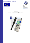
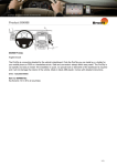
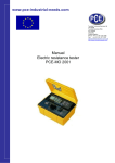
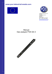
www.pce-industrial-needs.com
Tursdale Technical Services Ltd
Unit N12B
Tursdale Business Park
Co. Durham
DH6 5PG
United Kingdom
Phone: +44 ( 0 ) 191 377 3398
Fax: +44 ( 0 ) 191 377 3357
[email protected]
http://www.industrial-needs.com/
MANUAL
ELECTROMAGNETIC FIELD
RADIATION TESTER
EMF 823
[email protected]
Your purchase of this EMF TESTER marks a step forward for you into the field of recision
measurement. Although this EMF TESTER is a complex and delicate instrument, its durable
structure will allow many years of use if proper operating techniques are ,developed. Please
read the following instructions carefully and always keep this manual within easy reach.
Table of contents 1.Features ................................................................................................................................................. 3 2. Applications ......................................................................................................................................... 3 3. Caution of Electromagnetic Field Exposure ...................................................................................... 3 4. Specifications ....................................................................................................................................... 4 4-1 General Specifications ..................................................................................................................... 4 4-2 Electrical Specifications .................................................................................................................. 5 5. Front Panel Description ......................................................................................................................... 5 6. Measuring Procedure ........................................................................................................................... 6 6-1 EMF measurement ......................................................................................................................... 6 6-2 Data Hold ....................................................................................................................................... 7 6-3 Data Record ................................................................................................................................... 7 6-4 Display backlight On/Off ............................................................................................................... 7 6-5 Auto power OFF disable................................................................................................................. 7 7. Battery Replacement ............................................................................................................................ 7 8. Optional Accessories ........................................................................................................................... 8 2
[email protected]
1.Features
* The EMF tester is designed to provide user a quick, reliable and easy way to measure
electromagnetic field radiation levels around power lines, home appliances and industrial devices.
* Three EMF measuring ranges, 20 micro Tesla/200 micro Tesla /2000 micro Tesla and 200 mG/2000
mG/20000 mG.
* The EMF tester is a cost effective, hand-held instrument designed and calibrated to measure
electromagnetic field radiation at different bandwidths down to 50 Hz/60 Hz.
* Microprocessor circuit assures high accuracy and provides special functions and features.
* Records Maximum, Minimum readings with Recall.
* LCD dspaly is with the backlight installation.
* Auto power Off or manual power Off.
* Data hold.
* Operates from 006P DC 9V battery.
* Heavy duty & compact housing case.
2. Applications
This EMF tester is specifically designed to determine the magnitude of electromagnetic field radiation
generated by power lines, computer's monitor, TV sets, video machinery and many other similar devices.
3. Caution of Electromagnetic
Field Exposure
Claims by some scientists that long term exposure to electromagnetic field may be the cause of
childhood leukemia & other forms of cancer. Complete answers to any of these and related questions are
not currently available. At the present time the most common practice is to avoid excess exposure over
long period of time. "Prudent Avoidance" as stated by the Environmental Protection Agency(EPA) USA is
recommended.
3
[email protected]
4. Specifications
4-1 General Specifications
Display
Circuit
Measurement
EMF
Range
/Resolution
LCD size : 48.8 mm x 25.3 mm.
LCD is with the backlight installation.
Custom one-chip of microprocessor
LSI circuit.
EMF ( Electromagnetic field radiation )
micro Tesla :
20 micro Tesla x 0.01 micro Tesla
200 micro Tesla x 0.1 micro Tesla
2,000 micro Tesla x 1 micro Tesla
milli-Gauss :
200 mG x 0.1 mG
2,000 mG x 1 mG
20,000 mG x 10 mG
* mG : milli-Gauss
* 1 micro Tesla = 10 milli-Gauss
EMF Band
30 Hz to 300 Hz.
Axes no. of
Single axis.
Over-input
Sampling Time
Approx. 1 second.
Battery
DC 9 V battery (006P, 6F22).
Power Current
Approx. DC 5 mA.
* Back light Off.
Operating
0 to 50 Ԩ.
Temperature
Operating
Less than 80% R.H.
Humidity
Dimension
Weight
Accessories
Included
Optional
Accessories
152 x 69 x 36.3 mm
( 6.0 x 2.7 x 1.4 inch).
216 g/0.48 LB.
Operation Manual................... 1 PC.
* Soft carrying case, CA-52A
* AC to DC 9V power adapter.
4
[email protected]
4-2 Electrical Specifications
Range
Resolution
20 micro Tesla
0.01 micro Tesla
200 micro Tesla
0.1 micro Tesla
2,000 micro Tesla 1 micro Tesla
200 mG
0.1 mG
2,000 mG
1 mG
20,000 mG
10 mG
* mG : milli-Gauss
* 1 micro Tesla = 10 milli-Gauss
Range
Accuracy
20 micro Tesla
± (4 % + 3 d)
200 micro Tesla
± (5 % + 3 d)
2,000 micro Tesla ± (10 % + 5 d)
200 mG
± (4 % + 3 d)
2,000 mG
± (5 % + 3 d)
20,000 mG
± (10 % + 80 mG)
* Spec. accuracy tested under 50 Hz or 60 Hz.
@ Above specification tests under the environment RF
Field Strength less than 3 V/M & frequency less than
30 MHz only.
5. Front Panel Description
5-1 Display
5-2 Power Button
5
[email protected]
5-3 REC Button
5-4 HOLD Button
5-5 Range Button
5-6 Unit Button
5-7 Backlight Button
5-8 Tripod Fix Nut
5-9 Stand
5-10 Battery Cover/Compartmen
5-11 DC 9V Power Adapter Input Socket
5-12 EMF Sensor Position
6. Measuring Procedure
6-1 EMF measurement
1) Power On the meter by pressing the " Power Button "
( 5-2, Fig. 1 ) once.
Select the suitable range by pressing the " Range Button "
( 5-5, Fig. 1 )
Select the unit ( uT. mG ) by pressing the " Unit Button "
( 5-6, Fig. 1 )
* uT : micro Tesla, mG " milli-Gauss.
* For the unknown EMF measurement, start with the highest range and keep decreasing until the
higher resolution's reading is obtained.
2) With the tester in hand, move slowly towards to the object under measurement until it is physically
touched. The upper Display ( 5-1, Fig. 1 ) will present the EMF measurement value.
* EMF Sensor Position is in the area of " 5-13 , Fig. 1 ".
* Due to the electromagnetic interference of the
environment, the display reading may show small values before
testing, for example less than 0.05 micro Tesla. This is not malfunction
of the tester.
* Notice how the field intensity increases as you move
closer to the object.
3) Position the EMF tester at different angles to the object under measurement and observe how this
may affect your reading.
4) By trying different angles approaching the object under measurement, recorder the highest value
shown on the display.
* If the object under measurement is turned off during
the measurement, the EMF tester reading should then
return to zero, unless a field from other sources are detected.
Recommendation for EMF measurement
It is recommended to measure the presence of the electromagnetic field inside and outside of your
home and business locations regularly. As "hot spots" are detected by the EMF tester, rearrangement of the living and working areas is lightly recommended. Always try the best to avoid
long term exposure to strong electromagnetic field.
6
[email protected]
6-2 Data Hold
During the measurement, press the “Hold Button” (5-4, Fig. 1) once will hold the measured value & the
LCD will display a " HOLD " symbol.
* Press the “Hold Button “once again will release the data hold function.
6-3 Data Record ( Max., Min. reading )
* The data record function records the maximum and minimum readings. Press the "REC Button"
(5-3, Fig.)
1 ) once to start the Data Record function and there will be a " REC " symbol on the display.
* When the " REC " symbol on the display :
a) Press the " REC Button " ( 5-3, Fig. 1 ) once, the " REC MAX " symbol along with the maximum
value will appear on the display. If intend to delete the maximum value, just press the " Hold button " (
5-4, Fig. 1 ) once, the display will show the " REC " symbol only & execute the memory function
continuously.
b) Press the " REC button " ( 5-3, Fig. 1 ) again, the "REC. MIN." symbol along with the minimum
value will appear on the display. If intend to delete the minimum value, just press the " Hold button" (
5-4, Fig. 1 ) once, then the display will show the " REC " symbol only & execute the memory function
continuously.
c) To exit the memory record function, just press the " REC " button for 2 seconds at least. The
display will revert to the current reading.
6-4 Display backlight On/Off
During the measurement, the LCD backlight will On. If press the '" Backlight Button " ( 5-7, Fig. 1 ) once,
the LCD backlight will be switched to Off.
* Press the " Back light Button " once again will switch the
Display backlight installation On again.
6-5 Auto power OFF disable
The instrument has built-in " Auto Power OFF " in order to prolong battery life. The meter will switch off
automatically if none of the buttons are pressed within 10 min. To de-activate this feature, Select the
memory record function during measurement by pressing the " REC Button " ( 5-3, Fig. 1 ).
7. Battery Replacement
1) When the left corner of LCD display show "
, is necessary to replace the battery. However,
inspec. measurement may still be made for several hours after low battery indicator appears before
the instrument become inaccurate.
2) Slide the " Battery Cover " ( 5-10, Fig. 1 ) away from the instrument and remove the battery.
3) Replace with 9V battery ( Alkaline or Heavy duty type ) and reinstate the cover.
4) Make sure the battery cover is secured after changing the battery.
7
[email protected]
8. Optional Accessories
Soft carrying case
Model : CA-52A
* Soft carrying case with sash.
* Size : 200 x 80 x 50 mm.
* Input voltage : 100 to 240 ACV,
50/60 Hz.
* Output voltage : Regulation DC 9V/
1 Amp. rating max.
* Output plug : round 2.5 mm dia. plug.
PLUG CONVERTER * Convert the input plug of AP-9VA,
from the Germany type to USA type.
Model : AP-GTU
PLUG CONVERTER * Convert the input plug of AP-9VA,
Model : AP-GTE
from the Germany type to UK (
England ) type.
DC 9V POWER
ADAPTER
Model : AP-9VA
In this direction will find a vision of the measurement technique:
http://www.industrial-needs.com/measuring-instruments.htm
NOTE: "This instrument doesn’t have ATEX protection, so it should not be used in potentially explosive
atmospheres (powder, flammable gases)."
8