1
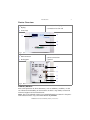
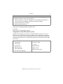
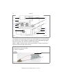
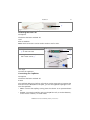
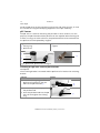
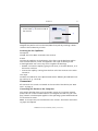
Conductivity Monitor CM 2.1S User Manual V6710 HPLC Table of Contents 3 Table of Contents Note: For your own safety, read the manual and always observe the warnings and safety information on the device and in the manual. Intended Use . . . . . . . . . . . . . . . . . . . . . . . . . . . . . . . . . . . . . . . . . . . . . . . . Features . . . . . . . . . . . . . . . . . . . . . . . . . . . . . . . . . . . . . . . . . . . . . . . . . . Device Overview . . . . . . . . . . . . . . . . . . . . . . . . . . . . . . . . . . . . . . . . . . . . Eluents/Buffers . . . . . . . . . . . . . . . . . . . . . . . . . . . . . . . . . . . . . . . . . . . . . 6 6 7 7 Scope of Delivery . . . . . . . . . . . . . . . . . . . . . . . . . . . . . . . . . . . . . . . . . . . . . 8 Safety for Users . . . . . . . . . . . . . . . . . . . . . . . . . . . . . . . . . . . . . . . . . . . . . . 8 Signal Words . . . . . . . . . . . . . . . . . . . . . . . . . . . . . . . . . . . . . . . . . . . . . . 10 Decontamination . . . . . . . . . . . . . . . . . . . . . . . . . . . . . . . . . . . . . . . . . . 10 Symbols and Signs . . . . . . . . . . . . . . . . . . . . . . . . . . . . . . . . . . . . . . . . . . . 11 Installation . . . . . . . . . . . . . . . . . . . . . . . . . . . . . . . . . . . . . . . . . . . . . . . . . Contacting the Technical Support . . . . . . . . . . . . . . . . . . . . . . . . . . . . . . Setup . . . . . . . . . . . . . . . . . . . . . . . . . . . . . . . . . . . . . . . . . . . . . . . . . . . Location Requirements . . . . . . . . . . . . . . . . . . . . . . . . . . . . . . . . . . . . Unpacking . . . . . . . . . . . . . . . . . . . . . . . . . . . . . . . . . . . . . . . . . . . . . Integration into the FPLC/HPLC System . . . . . . . . . . . . . . . . . . . . . . . Flow Cell . . . . . . . . . . . . . . . . . . . . . . . . . . . . . . . . . . . . . . . . . . . . . . . . . Attaching the Flow Cell . . . . . . . . . . . . . . . . . . . . . . . . . . . . . . . . . . . Connecting the Capillaries . . . . . . . . . . . . . . . . . . . . . . . . . . . . . . . . . pH Sensor . . . . . . . . . . . . . . . . . . . . . . . . . . . . . . . . . . . . . . . . . . . . . . . . Installing the pH Flow Cell and pH Electrode . . . . . . . . . . . . . . . . . . . Screwing On the Capillaries . . . . . . . . . . . . . . . . . . . . . . . . . . . . . . . . Connectors . . . . . . . . . . . . . . . . . . . . . . . . . . . . . . . . . . . . . . . . . . . . . . . Connecting the Device to the Computer . . . . . . . . . . . . . . . . . . . . . . Configuring the LAN Settings . . . . . . . . . . . . . . . . . . . . . . . . . . . . . . Connecting the Cables . . . . . . . . . . . . . . . . . . . . . . . . . . . . . . . . . . . . Configuring the Router . . . . . . . . . . . . . . . . . . . . . . . . . . . . . . . . . . . Integrating the LAN into a Company Network . . . . . . . . . . . . . . . . . . Controlling Several Systems Separately in a LAN . . . . . . . . . . . . . . . . Analog Output . . . . . . . . . . . . . . . . . . . . . . . . . . . . . . . . . . . . . . . . . . Power Connection . . . . . . . . . . . . . . . . . . . . . . . . . . . . . . . . . . . . . . . 11 11 12 12 12 13 14 15 15 16 16 17 17 17 18 18 19 19 20 20 21 Operation . . . . . . . . . . . . . . . . . . . . . . . . . . . . . . . . . . . . . . . . . . . . . . . . . . 21 Initial Start-Up . . . . . . . . . . . . . . . . . . . . . . . . . . . . . . . . . . . . . . . . . . . . 22 AZURA CM 2.1S User Manual, V6710, Version 2.0 4 Table of Contents Switch On . . . . . . . . . . . . . . . . . . . . . . . . . . . . . . . . . . . . . . . . . . . . . . . . Operating Elements . . . . . . . . . . . . . . . . . . . . . . . . . . . . . . . . . . . . . . Menu . . . . . . . . . . . . . . . . . . . . . . . . . . . . . . . . . . . . . . . . . . . . . . . . . Selecting the Interface . . . . . . . . . . . . . . . . . . . . . . . . . . . . . . . . . . . . . . Checking the Operating Hours . . . . . . . . . . . . . . . . . . . . . . . . . . . . . . . . Setting the Temperature Compensation . . . . . . . . . . . . . . . . . . . . . . . . . Entering the Calibration Points . . . . . . . . . . . . . . . . . . . . . . . . . . . . . . . . Specifying the Offset Value . . . . . . . . . . . . . . . . . . . . . . . . . . . . . . . . . . . Calibrating the pH Electrode . . . . . . . . . . . . . . . . . . . . . . . . . . . . . . . . . . Switching Off . . . . . . . . . . . . . . . . . . . . . . . . . . . . . . . . . . . . . . . . . . . . . 22 22 23 24 24 25 25 26 26 27 Functionality Tests . . . . . . . . . . . . . . . . . . . . . . . . . . . . . . . . . . . . . . . . . . . 28 Troubleshooting . . . . . . . . . . . . . . . . . . . . . . . . . . . . . . . . . . . . . . . . . . . . . 29 LAN . . . . . . . . . . . . . . . . . . . . . . . . . . . . . . . . . . . . . . . . . . . . . . . . . . . . 29 Maintenance and Care . . . . . . . . . . . . . . . . . . . . . . . . . . . . . . . . . . . . . . . . Maintenance Contract . . . . . . . . . . . . . . . . . . . . . . . . . . . . . . . . . . . . . . Caring for the Device . . . . . . . . . . . . . . . . . . . . . . . . . . . . . . . . . . . . . . . Flushing the Flow Cell . . . . . . . . . . . . . . . . . . . . . . . . . . . . . . . . . . . . . . . Replacing the Flow Cell . . . . . . . . . . . . . . . . . . . . . . . . . . . . . . . . . . . . . . 30 30 30 30 31 Transportation and Storage . . . . . . . . . . . . . . . . . . . . . . . . . . . . . . . . . . . Disassembly . . . . . . . . . . . . . . . . . . . . . . . . . . . . . . . . . . . . . . . . . . . . . . Disconnecting the Power Supply . . . . . . . . . . . . . . . . . . . . . . . . . . . . Removing the Flow Cell . . . . . . . . . . . . . . . . . . . . . . . . . . . . . . . . . . . Storage after Use . . . . . . . . . . . . . . . . . . . . . . . . . . . . . . . . . . . . . . . . . . 32 32 32 32 33 Technical Data . . . . . . . . . . . . . . . . . . . . . . . . . . . . . . . . . . . . . . . . . . . . . . 33 Repeat Orders . . . . . . . . . . . . . . . . . . . . . . . . . . . . . . . . . . . . . . . . . . . . . . 34 Disposal . . . . . . . . . . . . . . . . . . . . . . . . . . . . . . . . . . . . . . . . . . . . . . . . . . . 34 Legal Information . . . . . . . . . . . . . . . . . . . . . . . . . . . . . . . . . . . . . . . . . . . 35 Warranty Conditions . . . . . . . . . . . . . . . . . . . . . . . . . . . . . . . . . . . . . . . . 35 Transport Damage . . . . . . . . . . . . . . . . . . . . . . . . . . . . . . . . . . . . . . . . . 35 Index . . . . . . . . . . . . . . . . . . . . . . . . . . . . . . . . . . . . . . . . . . . . . . . . . . . . . 36 Declaration of Conformity . . . . . . . . . . . . . . . . . . . . . . . . . . . . . . . . . . . . . 38 AZURA CM 2.1S User Manual, V6710, Version 2.0 Table of Contents 5 To whom it may concern In case you prefer a French language user manual for this product, submit your request including the corresponding serial number via email or fax to KNAUER: [email protected] +49 30 8015010 Thank you. A qui que ce soit Si jamais vous préfériez un manuel en francais pour ce poduit contacter KNAUER par email ou par fax avec le no. de série: [email protected] +49 30 8015010 AZURA CM 2.1S User Manual, V6710, Version 2.0 6 Intended Use Intended Use Note: Only use the device for applications that fall within the range of the intended use. Otherwise, the protective and safety equipment of the device could fail. Description The conductivity monitor CM 2.1S measures the electrical resistance of buffer solutions containing salts and thus shows their conductivity. By doing so, programmed buffer gradients can be traced during a FPLC/HPLC run. The monitor consists of a processing device and a flow cell, and can additionally be used with a pH sensor. The pH flow cell and the pH electrode must be ordered separately. In case you are not using the pH sensor, you have to protect the connector on the device front with a blind connector that comes with the delivery. Operating Range The monitor is used for salinity gradient monitoring in the following areas: biochromatography process analysis biochemical analysis pharmaceutical analysis environmental analysis Features The conductivity monitor is non-contacting and maintenance free, as liquids only flow through the flow cell and can not enter the processing device. The non-contacting tracer is made of aluminum and PEEK. Flow Cells Flow cells with flow rate ranges between 0 – 10 ml/min, 10 – 100 ml/min are available. The flow cell is not included with the delivery but can be purchased separately. 1/16" capillaries are part of the flow cell and serve to connect the flow cell to the FPLC/HPLC system. pH Sensor The pH sensor consists of a pH electrode and a pH flow cell. You can mount the pH flow cell onto the device with a mounting bracket. The pH sensor and the mounting bracket are not included with the delivery but can be purchased separately. An included bypass allows the closure of the flow cell after the pH electrode has been disassembled. AZURA CM 2.1S User Manual, V6710, Version 2.0 Intended Use 7 Device Overview Legend 3 connection for display 4 connection for flow cell 1 display 2 arrow keys 2 1 3 4 Fig. 1 front view Legend 7 RS-232 connector 8 power connection 9 ground 5 LAN connector 6 Analog port 5 6 7 8 9 Fig. 2 Rear View Eluents/Buffers Even small quantities of other substances, such as additives, modifiers, or salts can influence the durability of the materials. If there is any doubt, contact the Technical Support of the manufacturer. Note: The list of selected solvents was compiled based on research in the pertinent literature and is only a recommendation by KNAUER. AZURA CM 2.1S User Manual, V6710, Version 2.0 8 Scope of Delivery Suitable Eluents/Buffers acetate buffer solutions acetone benzene chloroform ethyl acetate ethanol formiate buffer solution isopropanol potassium chloride carbon dioxide methanol sodium chloride phosphate buffer solutions toluol ammoniated dilute solution dilute acetic acid dilute sodium hydroxide water Unsuitable Eluents/Buffers acetonitrile Scope of Delivery Note: Only use original parts and accessories made by the manufacturer or a company authorized by the manufacturer. conductivity monitor CM 2.1S user manual mains power connection 110 V – 240 V, voltage output: 24 V/60 W power cable CM 2.1S accessories kit Safety for Users Professional Group The user manual addresses persons who are qualified as chemical laboratory technicians or have completed comparable vocational training. The following knowledge is required: Fundamental knowledge of liquid chromatography AZURA CM 2.1S User Manual, V6710, Version 2.0 Safety for Users 9 Knowledge regarding substances that are suitable only to a limited extent for use in liquid chromatography Knowledge regarding the health risks of chemicals Participation during an installation of a device or a training by the company KNAUER or an authorized company. If you do not belong to this or a comparable professional group, you may not perform the work described in this user manual under any circumstances. In this case, please contact your superior. Safety Equipment When working with the device, take measures according to lab regulations and wear protective clothing: Safety glasses with side protection Protective gloves Lab coat What must be taken into account? All safety instructions in the user manual The environmental, installation, and connection specifications in the user manual National and international regulations pertaining to laboratory work Original spare parts, tools, and solvents made or recommended by KNAUER Good Laboratory Practice (GLP) Accident prevention regulations published by the accident insurance companies for laboratory work Filtration of substances under analysis Use of inline filters Once they have been used, never re-use capillaries in other areas of the HPLC system. Only use a given PEEK fitting for one specific port and never re-use it for other ports. Always install new PEEK fittings on each separate port. Follow KNAUER or manufacturer's instructions on caring for the columns More safety-relevant information is listed below: flammability: Organic solvents are highly flammable. Since capillaries can detach from their screw fittings and allow solvent to escape, it is prohibited to have any open flames near the analytical system. solvent tray: Risk of electrical shock or short circuit if liquids get into the device's interior. For this reason, place all bottles in a solvent tray. solvent lines: Install capillaries and tubing in such a way that liquids cannot get into the interior in case of a leak. leaks: Regularly check if any system components are leaking. AZURA CM 2.1S User Manual, V6710, Version 2.0 10 Safety for Users power cable: Defective power cables are not to be used to connect the device and the power supply system. self-ignition point: Only use eluents that have a self-ignition point higher than 150 °C under normal ambient conditions. power strip: If several devices are connected to one power strip, always consider the maximum power consumption of each device. power supply: Only connect devices to voltage sources, whose voltage equals the device's voltage. toxicity: Organic eluents are toxic above a certain concentration. Ensure that work areas are always well-ventilated! Wear protective gloves and safety glasses when working on the device! Where is use of the device prohibited? Never use the system in potentially explosive atmospheres without appropriate protective equipment. For further information, contact the Technical Support of KNAUER. Decommissioning the Device Securely At any time, take the device completely out of operation by either switching off the power switch or by pulling the power plug. Opening the Device The device may be opened by the KNAUER Technical Support or any company authorized by KNAUER only. Signal Words Possible dangers related to the device are divided into personal and material damage in this user manual. Lethal injuries will occur. Serious or moderate injuries can occur. Minor injuries can occur. Device defects can occur. Decontamination Contamination of devices with toxic, infectious or radioactive substances poses a hazard for all persons during operation, repair, sale, and disposal of a device. AZURA CM 2.1S User Manual, V6710, Version 2.0 Symbols and Signs 11 Life-threatening injuries Health danger if getting in contact with toxic, infectious or radio-active substances. Before disposing of the device or sending it away for repair, you are required to decontaminate the device in a technically correct manner. All contaminated devices must be properly decontaminated by a specialist company or the operating company before they can be recommissioned, repaired, sold, or disposed of. All materials or fluids used for decontamination must be collected separately and disposed of properly. Symbols and Signs The following symbols and signs are used on the device, in the chromatography software or in the user manual: Symbol Meaning warning signs Electrostatic-discharge hazard warning signs Electric shock hazard CE Mark Device fulfills the requirements of the Conformité Européenne, which is confirmed by the Declaration of Conformity. Installation Contacting the Technical Support You have various options to contact the Technical Support: Telephone:+49 30 809727-111 Fax:+49 30 8015010 E-Mail:[email protected] You can make your requests in English and German. AZURA CM 2.1S User Manual, V6710, Version 2.0 12 Installation Setup When installing the device, please pay attention to the suitability of the location according to the requirements. The setup requirements and a description can be found in the following section. Location Requirements Device defect The device overheats at exposure to sunlight and insufficient air circulation. Device failures are very likely. Set up the device in such a way that it is protected against exposure to direct sunlight. Keep at least 15 cm clear at the rear and 5–10 cm at each side for air circulation. The intended use is only ensured if the requirements of the operating environment are met (see ambient conditions in the chapter Technical Data). sunlight: Protect the device against direct exposure to sunlight. A/C system: Set up the device at a location not exposed to air drafts. vibration: Do not set up the device in the vicinity of other machines that cause floor vibrations. Unpacking Prerequisites There is no noticeable damage to the packaging. Tools utility knife Bruises Damage to the device by carrying or lifting it on protruding housing parts. The device may fall and thus cause injuries. Lift the device on the side of the housing only. Process 1. Set-up the package in such a way that you can read the label.. Using the utility knife, cut the adhesive tape and open the packaging. 2. Remove the foam insert. Take out the accessories kit and the manual. 3. Open the accessories kit. Check the scope of delivery. In case any parts are missing, contact the Technical Support. AZURA CM 2.1S User Manual, V6710, Version 2.0 Installation 13 Process 4. Clasp the device at its side panels and lift it out of the packaging. 5. Remove the foam inserts from the device. 6. Check the device for signs of damage that occurred during transport. In case you notice any damage, contact the Technical Support. 7. Set-up the device in its location. 8. Remove the protective foil. Transport Lock The monitor is delivered without transport lock. Next Steps Carefully store all packaging material. Integration into the FPLC/HPLC System Integrate the conductivity monitor into the FPLC/HPLC system. In case you want to use the conductivity monitor together with an UV detector and a pH sensor in one system, you should position the monitor behind the UV detector and before the pH flow cell, as the pH electrode has a maximum pressure stability of 5 bar. Legend 1 2 3 4 5 6 waste bottle solvent tray pump heads pressure sensor mixing chamber 7 solvent bottles 8 injection valve 9 column bl pH electrode bm pH flow cell bn flow cell of monitor flow cell of UV detector AZURA CM 2.1S User Manual, V6710, Version 2.0 14 Installation 7 1 8 2 9 3 4 5 bl bm 6 bn Fig. 3 Example: Connection of a binary FPLC gradient system with a UV detector Flow Cell The capillaries are attached to the flow cell. These capillaries can not be undone from the flow cell. If the capillary is clogged and cannot be cleaned by repeatedly flushing with water, the flow cell has to be replaced. There is a plug on the rear side of the flow cell, which is used to connect the flow cell to the front side of the monitor. Legend 1 specification of flow cell type 2 holes for installation 3 plug 1 2 Fig. 4 flow cell: front with designation AZURA CM 2.1S User Manual, V6710, Version 2.0 Installation 15 3 Fig. 5 flow cell: rear side with plug Attaching the Flow Cell Prerequisites The device has been switched off. Tools Allen screwdriver Note: Both connections can be used as outlet as well as inlet. Process Figure 1. Plug the flow cell onto the socket 1 on the front side. 2. Using the screwdriver, unscrew the 2 outer screws 2. 1 2 Next Steps Connect the capillaries. Connecting the Capillaries Prerequisites The device has been switched off. Process The capillaries belong to the flow cell and can not be removed. To integrate the flow cell into the FPLC/HPLC flow path, you use the supplied couplings to connect the capillaries. INLET: Connect the capillary coming from the column or an upstream detector. OUTLET: Connect the capillary going to the pH flow cell, to another detector, to the fraction collector, or to the waste. AZURA CM 2.1S User Manual, V6710, Version 2.0 16 Installation Next Steps Install the pH sensor at the connection on the front side of the monitor, or close the connection using the blind plug supplied in the scope of delivery. pH Sensor The pH sensor is used for measuring the pH value in saline solutions. For this purpose, the pH electrode and the pH flow cell are required. When flushing the monitor or using non-saline solutions, the pH electrode has to be removed from the pH flow cell and replaced by a bypass. Legend 3 pH electrode with protective cap 4 bypass 1 locking ring 2 pH flow cell 1 4 2 3 Fig. 6 pH flow cell, pH electrode, and bypass Installing the pH Flow Cell and pH Electrode Prerequisites The mounting bracket is mounted and the pH flow cell is fixed to the mounting bracket. Process Figure 1. Screw the locking ring 2 off the pH flow cell and pull it over the cable of the pH electrode 1. 2. Remove the protective cap 3 from the pH electrode. 3. Insert the pH electrode into the pH flow cell and tighten the locking ring. AZURA CM 2.1S User Manual, V6710, Version 2.0 1 2 3 Installation Process 17 Figure 4. Connect the plug of the electrode to the socket 4 on the front side of the monitor. 4 Next Steps Integrate the pH flow cell into the FPLC/HPLC flow path by installing it downstream of the conductivity monitor. Screwing On the Capillaries Prerequisites The pH sensor has been mounted to the monitor. Process Connect the capillaries in the direction of the flow. Use the bushings and ferrules with flat bottoms, which are supplied in the scope of delivery of the mounting bracket. Do not use any tools to tighten the bushings. OUTLET: Connect the capillary going to the waste, to another detector, or to the fraction collector. Connect the capillary coming from the flow cell of the monitor to the other connector. Next Steps Conduct the calibration of the pH electrode with 2 different pH calibration buffer solutions (e. g. 7 and 10). Connectors All connectors for control are located on the rear side of the device (see “Rear View” on page 7). Connecting the Device to the Computer This section describes how to set up an HPLC system in a local area network (LAN) and how a network administrator can integrate this LAN into your company network. The description applies to the operating system Windows® and all conventional routers. Note: To set up a LAN, we recommend to use a router. That means the following steps are required: AZURA CM 2.1S User Manual, V6710, Version 2.0 18 Installation Process 1. 2. 3. 4. 5. On the computer, go to the control panel and check the LAN properties. Hook up the router to the devices and the computer. On the computer, configure the router to set up the network. Install the chromatography software from the data storage device. Switch on the device and run the chromatography software. Configuring the LAN Settings The LAN uses only one server (which is normally the router) from that the devices automatically receive their IP address. Prerequisite In Windows®, power saving, hibernation, standby, and screen saver must be deactived. In case you use an USB-to-COM box, the option "Allow the computer to turn off ths device to save power" in the devicemanager must be deactivated for all USB hosts. Only for Windows 7: For the network adapter, the option "Allow the computer to turn off this device to save power" in the Device Manager must be deactivated. Process 1. In Windows 7 choose Start Control Panel Network and Sharing Center. 2. Double-click on LAN Connection. 3. Click on the button Properties. 4. Select Internet Protocol version 4 (TCP/IPv4). 5. Click on the button Properties. 6. Check the settings in the tab General. The correct settings for the DHCP client are: a) Obtain IP address automatically b) Obtain DNS server address automatically 7. Click on the button OK. Connecting the Cables A router 3 has several LAN ports 2 and one WAN port 4 that can be used to integrate the LAN into a wide area network (WAN), e.g. a company network or the Internet. In contrast, the LAN ports serve to set up a network from devices 1 and a computer 5. To avoid interference, we recommend operating the HPLC system separately from the company network. AZURA CM 2.1S User Manual, V6710, Version 2.0 Installation 1 2 3 4 19 5 You will find patch cables for each device and the router in the accessories kit. To connect the router to a WAN, an additional patch cable is required, which is not supplied within the scope of delivery. Prerequisite The computer has been switched off. There is a patch cable for each device and the computer. Process 1. Use the patch cable to connect the router and the computer. Repeat this step to connect all devices. 2. Use the power supply to connect the router to the mains power system. Configuring the Router The router is preset at the factory. You will find a label at the bottom side of the router, on which IP address, user name, and password are printed. These information help to open the router configuration. Process 1. To open the router configuration, start your Internet browser and enter the IP address (not for all routers). 2. Enter user name and password. 3. Configure the router as DHCP server. 4. In the router configuration, check the IP address range and make changes if necessary. Result Once the router has assigned IP addresses to all devices, the chromatography software can be used to remotely control the system. Integrating the LAN into a Company Network A network administrator can integrate the LAN into your company network. In this case you use the WAN port of the router. AZURA CM 2.1S User Manual, V6710, Version 2.0 20 Installation Prerequisite There is a patch cable for the connection. Process 1. Check that the IP address range of the router and of the company network do not overlap. 2. In case of an overlap, change the IP address range of the router. 3. Use the patch cable to connect the router WAN port to the company network. 4. Restart all devices, including the computer. Controlling Several Systems Separately in a LAN Devices connected to a LAN communicate through ports, which are part of the IP address. If more than one HPLC system is connected to the same LAN and you plan on controlling them separately, you can use different ports to avoid interference. Therefore, the port number for each device must be changed and this same number must be entered into the device configuration of the chromatography software. We recommend to use the same port number for all devices in the same system. Note: The port is set to 10001 at the factory. You must use the same numbers in the device configuration of the chromatography software as in the device, otherwise the connection fails. Process 1. Find out port number and change it on the device. 2. Enter the port number in the chromatography software. Result The connection is established. Note: If the LAN cable has been connected and the connection is valid, the LED on the LAN port on the rear side lights up in green. The second LED blinks yellow during data transfer. software The conductivity monitor is embedded in the software packages OpenLAB, ClarityChrom (from version 5) and PurityChrom. Analog Output The device sends out measuring signals via the analog output as varying voltage. Pay attention to the following conversion factors: pH Value: pH 0 = 50 mV pH 7 = 500 mV pH 14 = 950 mV AZURA CM 2.1S User Manual, V6710, Version 2.0 Operation 21 Conductivity: The measured conductivity (mS/cm) is converted directly to voltage (mV), thus 1 mS/cm = 1 mV. Power Connection The devices are equipped with an universal switched-mode power supply rated for 100–240 V AC. The switched-mode power supply automatically selects the correct supply voltage. Supply voltage: 115 ± 15 % or 230 ± 10 % VACs Frequency: 50/60 Hz 1 on/off switch 2 LED 1 2 Fig. 7 Mains power connection Electric shock Electric shock hazard caused by an improperly grounded power connection. Ground the power connection according to the pertinent regulations. Use a three-conductor line cord. Process Figure 1. Set the on/off switch 1 to the OFF position 2. Connect the power supply to the device and afterwards plug the power plug into the socket. 1 Next Steps Set the on/off switch to the ON position and start up the device. Operation The device is exclusively operated by means of the membrane keyboard. Operation via the software is not possible. The software monitors the measurement. AZURA CM 2.1S User Manual, V6710, Version 2.0 22 Operation Initial Start-Up In case the monitor is part of a FPLC/HPLC system, check for the following criteria: A connection to the computer via the desired interface has been established (see “Connectors” on page 17). The software has been installed. The flow cell has been mounted according to the instructions. Switch On Prerequisites The device has been installed at a suitable site. The device has been connected to power mains connection. The installation has been completed. Process Figure 1. Set the on/off switch 1 to the ON position 1 Result The display lights up and the green LED on the power supply indicates that the device is supplied with power. Next Steps Conduct the calibration of the pH electrode with 2 different pH calibration buffer solutions (e. g. 7 and 10), to finalize the start-up. Operating Elements Display and keypad Explanation Fig. 8 status display The status display shows the conductivity (line 1), the current gradient composition (line 2, left), and the pH value (line 2, right). Fig. 9 arrow keys Press both arrow keys simultaneously to activate the keypad.. Hold down 1 arrow key to scroll with the other arrow key through the menus. Press any one of the arrow keys to set values and to change settings. AZURA CM 2.1S User Manual, V6710, Version 2.0 Operation 23 Menu Display content Description The measuring signal can offset within a set range between -10 % and +10 %. You can set a correction factor and a reference temperature for the temperature sensor inside the flow cell. The difference between the real and the benchmark temperature and the correction factor is used to correct the conductivity measurement value. benchmark correction factor is 1.7 % benchmark temperature difference is 25 °C Use the menus Factor 1-4 to define up to 4 calibration points. Enter the conductivity or the correction factor for each point to generate the correct calibration curve. 2 menus help to calibrate the pH sensor: #0 is preset to pH07 #1 can be adjusted to a value between pH02....pH12 and corresponds to the pH value of the second calibration solution that is used Select this menu to view the serial number of the monitor. Select this menu to view the serial number of the flow cell. Select this menu to view the operating hours of the monitor. Use this menu to select an interface for the PC connection: LAN DHCP 9600 Baud (RS 232) Use this menu to view the progress of the programmed buffer gradient in the status display. To do so, it is necessary to enter the conductivity of the initial concentration of the programmed gradient first. AZURA CM 2.1S User Manual, V6710, Version 2.0 24 Display content Operation Description In this menu, enter the conductivity of the final concentration of the programmed buffer gradient. Selecting the Interface To view the measuring results of the conductivity monitor via software, the interface you use must be selected on the device: PC: LAN DHCP PC: 9600 Baud (RS-232) Prerequisites A physical connection has been established. The monitor has been switched on. Process Display content 1. Press both arrow keys. 2. Hold down the left arrow key and use the right arrow key to scroll until the correct display appears. 3. Let go of the arrow keys and press the left or right arrow key to select an option. Next Steps Check if the conductivity monitor appears in the software. Checking the Operating Hours The operating hours of the monitor can be viewed in the GLP menu, which displays the value in hours according to GLP specifications. Prerequisites The monitor has been switched on. Process Display content 1. Press both arrow keys. 2. Hold down the left arrow key and use the right arrow key to scroll until the correct display appears. 3. Let go of the arrow keys. Next Steps Enter additional settings or start the analysis. AZURA CM 2.1S User Manual, V6710, Version 2.0 Operation 25 Setting the Temperature Compensation Ions that have dissolved in water vary in their conductivity depending on temperature. The conductivity of electrolytic solutions, e. g. 1 M NaCl solutions, increases on average by around 2 % per °C. The default temperature setting of the device is 25 °C. In order to account for the deviation in conductivity at different ambient temperatures, the value has to be corrected in the TEMP-COR menu. Use 1 M NaCl solution (86.6 mS/cm at 25 °C) as standard. The benchmark for the correction factor is 1.7 %. Prerequisites The monitor has been switched on. Process Display content 1. Press both arrow keys. 2. Hold down the left arrow key and use the right arrow key to scroll until the correct display appears. 3. Let go of the arrow keys and press the left or right arrow key to select a value. Next Steps Enter additional settings or start the analysis. Entering the Calibration Points You have the possibility to enter 4 independent calibration points in the FACTOR menu. Then enter the expected conductivity (1...988 mS/cm) or correction factor (50...200 %) for each calibration point. Take the following formula into account: 0 < Factor 1 < Factor 2 < Factor 3 < Factor 4 < SCE (scale end value = maximum conductivity). Presets The following values are preset: Factor 1: 29 mS/cm at 116 % Factor 2: 50 mS/cm at 104 % Factor 3: 70 mS/cm at 100 % Factor 4: 92 mS/cm at 94 % Prerequisites The monitor has been switched on. AZURA CM 2.1S User Manual, V6710, Version 2.0 26 Operation Process Display content 1. Press both arrow keys. 2. Hold down the left arrow key and use the right arrow key to scroll until the correct display appears. 3. Let go of the arrow keys and press the left or right arrow key to select a value. 4. Wait until the status display shows.. 5. Press both arrow keys. 6. Hold down the left arrow key and use the right arrow key to scroll until the correct display appears. 7. Let go of the arrow keys and press the left or right arrow key to select a value. Next Steps Enter additional settings or start the analysis. Specifying the Offset Value The conductivity monitor has no automatic calibration. To make analysis results more comparable, specify a value between -10.0 % and +10.0 % in the OFFSET menu for shifting the measurement values. Meaning if the measuring value corrected to 25 °C does not match the benchmark of 86.6 mS/cm for a 1 M NaCl solution, you can use the offset value to adjust the displayed measuring value. Prerequisites The monitor has been switched on. Process Display content 1. Press both arrow keys. 2. Hold down the left arrow key and use the right arrow key to scroll until the correct display appears. 3. Let go of the arrow keys and press the left or right arrow key to select a value. Next Steps Enter additional settings or start the analysis. Calibrating the pH Electrode To calibrate the pH electrode for initial start-up, you use the preset value of pH7 and a second value according to the calibration solution in use (e. g. 4, 10). Please pay attention to the indicated measuring values in mV to control the correct pH values in the second line of the monitor display. Benchmark values can be taken from the succeeding table. AZURA CM 2.1S User Manual, V6710, Version 2.0 Operation 27 pH Measuring value (mV) pH Measuring value (mV) 2 +300 8 -60 3 +240 9 -120 4 +180 10 -180 5 +120 11 -240 6 +60 12 -300 7 +/-60 Prerequisites The monitor has been switched on. Process Display content 1. Press both arrow keys. 2. Hold down the left arrow key and use the right arrow key to scroll until the correct display appears. 3. Let go of the arrow keys and press the left or right arrow key to select a value. 4. Wait until the status display shows.. 5. Press both arrow keys. 6. Hold down the left arrow key and use the right arrow key to scroll until the correct display appears. 7. Hold down the left arrow key and use the right arrow key to switch to ON. 8. Let go of the arrow keys and wait until the display shows the measuring value. 9. Keep waiting until the value stabilizes. Press any key. 10.Press the right arrow key to save the result or the left arrow key to cancel. Next Steps Enter additional settings or start the analysis. Switching Off Prerequisites The system has been flushed with water. AZURA CM 2.1S User Manual, V6710, Version 2.0 28 Functionality Tests Process Figure 1. Set the on/off switch on the power supply to the OFF 1 position 1 Result The display and the LED on the power supply go out. Next Steps Disconnect the power supply from the mains power connection and pay attention to the information in the chapter on storage. Functionality Tests Installation Qualification (IQ) The customer may request the Installation Qualification, which is free of charge. In case of a request, the Technical Support of KNAUER or from a provider authorized by KNAUER performs this functionality test during the installation. The Installation Qualification is a standardized document that comes as part of the delivery and includes the following: confirmation of flawless condition at delivery check if the delivery is complete certification on the functionality of the device Operation Qualification (OQ) The Operation Qualification includes an extensive functionality test and must be purchased from the manufacturer. Contact the KNAUER Sales Department to request an offer. The Operation Qualification is a standardized KNAUER document and includes the following: definition of customer requirements and acceptance terms documentation on device specifications device functionality check at installation site Test Intervals To make sure that the device operates within the specified range, you should test the device using the Operation Qualification at following intervals: Every 3 months: average useful life of more than 5 days/week or 24 hours/ day; when operating with buffer solutions or other salt solutions: Every 6 months: average useful life of 1 to 5 days/week AZURA CM 2.1S User Manual, V6710, Version 2.0 Troubleshooting 29 Execution The test can be carried out either by the Technical Support of KNAUER or from a provider authorized by KNAUER. Troubleshooting If the device stops functioning or there are connection problems, start by checking the following items: Is the display on? Are the LEDs of the LAN connector on? When you connect the cable, the green LED goes on. The second LED blinks yellow during data transfer. Is the LED of the power supply on? LAN Go through the following steps, in case no connection between the computer and the devices can be established. Check after each step if the problem is solved. If the problem cannot be located, call the Technical Support. 1. Check the status of the LAN connection in the Windows task bar: Connected Connection not established If no connection was established, test the following: Is the router switched on? Is the patch cable connected correctly to the router and the computer? 2. Check the router settings: Is the router set to DCHP server? Is the IP address range sufficient for all the connected devices? 3. Check all connections: Are the patch cable connected to the LAN ports and not the WAN port? Are all cable connections between devices and router correct? Are the cables plugged in tightly? 4. If the router is integrated into a company network, pull out the patch cable from the WAN port. Can the devices communicate with the computer, even though the router is disconnected from the company network? 5. Turn off all devices, router, and computer. Firstly, turn on the router and secondly turn on the devices and the computer. Has this been successful? 6. Replace the patch cable to the device with that no connection could be established. AZURA CM 2.1S User Manual, V6710, Version 2.0 30 Maintenance and Care Has this been successful? 7. Make sure that the IP port of the device matches the port in the chromatography software. Maintenance and Care Proper maintenance of your devices will ensure successful analyses and reproducible results. Maintenance Contract The following maintenance work on the device may only be performed by the manufacturer or a company authorized by the manufacturer and is covered by a separate maintenance contract: Opening the Module Removing the hood or the side panels. Caring for the Device Prerequisites The monitor has been switched off. The power plug has been pulled. Device defect Intruding liquids can cause damage to the device. Place solvent bottles next to the device or in a solvent tray. Moisten the cleaning cloth only slightly. Clean all smooth surfaces of the device with a wet cloth and a mild commercially available cleaning solution or isopropanol. Flushing the Flow Cell It is very important to flush the complete system thoroughly with water after finishing work. Before flushing, you have to replace the pH electrode with the bypass. You need to flush out all salts before using isopropanol. But in most cases this is not necessary. Clogged flow cells may lead to increased system pressure and reduced sensitivity. Thus generally flush the conductivity monitor with water. Occurring contamination can often be removed by repeatedly flushing the flow cell. In case there is no time for flushing, you may run the sytem with buffer at a low flow rate (e. g. 0.1 ml/min) until the next use. Flushing solution The following solvents are recommended for flushing: water AZURA CM 2.1S User Manual, V6710, Version 2.0 Maintenance and Care 31 isopropanol Prerequisites The bypass has been inserted into the pH flow cell. Tools pump or syringe Performance decrease Oil drops can contaminate the flow cell. Do not use compressed air for drying. Note: Never use organic solvents for flushing after working with buffers. Always flush with water first. Process 1. Using the pump or syringe, flush generously with water. 2. Fill the syringe with air and blow the air through the capillary. Next Steps Check the system pressure and sensitivity. Replacing the Flow Cell Prerequisites The device has been switched off. The power plug has been pulled. The capillary connections have been disconnected from the FPLC/HPLC system. Tools Phillips screwdriver Note: Make sure that you loosen the outer screws. Loosening the inner screws opens the flow cell. Process Figure 1. Using the screwdriver, undo the 2 outer screws 2 of the flow cell. 2. Unplug the flow cell from the front. AZURA CM 2.1S User Manual, V6710, Version 2.0 1 32 Transportation and Storage Process Figure 3. Plug the new flow cell onto the connector 2. 4. Using the screwdriver, tighten the 2 outer screws. 2 Next Steps Attach the capillaries and plug in the power plug. Transportation and Storage Carefully prepare the device for transport or storage. If you want to return your device to KNAUER for repairs, enclose the Service Request Form which can be downloaded from our website. You will find the document in the Service are und Technical Support. Disassembly Before transport, the capillary inside the flow cell must be flushed with water and dried with air (see “Flushing the Flow Cell” on page 30). The flow cell should be removed for better packaging of the device. Disconnecting the Power Supply Prerequisites The device has been switched off. Process 1. Pull the power supply out of the socket and afterwards remove the plug from the device. 2. Package the power supply and store it nearby the device. Removing the Flow Cell Prerequisites The device has been switched off. The power plug has been pulled. The capillaries have been removed. Tools Phillips screwdriver AZURA CM 2.1S User Manual, V6710, Version 2.0 Technical Data Process 33 Figure 1. Using the screwdriver, undo the 2 outer screws 2. 2. Unplug the flow cell from the front. 1 Next Steps Carefully package the device for transportation or storage. Storage after Use The functionality of the device remains warranted, if you select a storage location according to the following ambient conditions: temperature range 4 – 40 °C; 39.2 – 104 °F air humidity below 90%, non-condensing air pressure 84 – 106 kPa; 840 – 1060 mbar Store the pH electrode in a saturated KCl solution. Technical Data detector type conductivity monitor conductivity 0.1–999 mS/cm accuracy <5 % scale end value precision in measured <2 % of end value or 5 S/cm of higher values range (0.1-300 mS/cm) linearity ±1 % scale end value pH measured range pH 2-12 pH precision ±0.2 pH in temperature range 4–25 °C pH accuracy ±0.5 pH in temperature range 4–25 °C pH drift maximum 0.02 pH/h at pH 4 maximum data rate 5 Hz (LAN, RS-232, Analog) outputs LAN, RS-232, Analog analog output conductivity, pH control manual: front panel protection type IP 20 AZURA CM 2.1S User Manual, V6710, Version 2.0 34 Repeat Orders Repeat Orders Note: For repeat orders of spare parts use the enclosed packing list. Contact the Technical Support in case there are any questions on spare parts or accessories. Device and Accessories Name Order Number CM 2.1S ADG30 pH option kit (pH electrode, pH flow cell, bypass) A70091 pH electrode A1938 bypass A1934 pH flow cell A1939 mounting bracket A9854 Flow Cells for Conductivity Monitor Name Order Number 10 ml flow cell A4156 100 ml flow cell A4157 Disposal Hand in old devices or disassembled old components at a certified waste facility, where they will be disposed of properly. AVV Marking in Germany According to the German "Abfallverzeichnisverordnung" (AVV) (January, 2001), old devices manufactured by KNAUER are marked as waste electrical and electronic equipment: 160214. WEEE Registration KNAUER as a company is registered by the WEEE number DE 34642789 in the German "Elektroaltgeräteregister" (EAR). The number belongs to category 8 and 9, which, among others, comprise laboratory equipment. All distributors and importers are responsible for the disposal of old devices, as defined by the WEEE directive. End-users can send their old devices manufactured by KNAUER back to the distributor, the importer, or the company free of charge, but would be charged for the disposal. Solvents and Other Operating Materials All solvents and other operating materials must be collected separately and disposed of properly. AZURA CM 2.1S User Manual, V6710, Version 2.0 Legal Information 35 All wetted components of a device, e. g. flow cells of detectors or pump heads and pressure sensors for pumps, have to be flushed first with isopropanol and then with water before being maintained, disassembled or disposed. Legal Information Warranty Conditions The factory warranty for the device is valid for 12 months after the date of dispatch. All warranty claims shall expire in the event that any unauthorized changes are made to the device. During the warranty period, any components with material or design-related defects will be replaced or repaired by the manufacturer free of charge. This warranty excludes the following: accidental or willful damage damage or errors caused by third parties that are not contractually related to the manufacturer at the time the damage occurs wear parts, fuses, glass parts, columns, light sources, cuvettes and other optical components damage caused by negligence or improper operation of the device and damage caused by clogged capillary packaging and transport damage In the event of device malfunctions, directly contact the manufacturer. KNAUER Wissenschaftliche Geräte GmbH Hegauer Weg 38 14163 Berlin, Germany Phone: +49 30 809727-111 Telefax: +49 30 8015010 e-mail: [email protected] Internet: www.knauer.net Transport Damage The packaging of our devices provides the best possible protection against transport damage. Check the devices for signs of transport damage. In case you notice any damage, contact the Technical Support and the forwarder company within three workdays. AZURA CM 2.1S User Manual, V6710, Version 2.0 36 Index Index A Accessories 34 accessories 8, 12 additives 7 analog output 20 AVV marking 34 problems 29 router 19 settings 18 setup 18 leak 9 location 12 B buffer 7 bypass figure 16 M maintenance 30 Maintenance Contract 30 markings 11 menu 23 modifiers 7 monitor description 6 features 6 operating range 6 order number 34 C calibration point 25 capillary flow cell 6, 15 pH sensor 17 care 30 connectors 7, 21 contact 11 D declaration of conformity 38 decontamination 10 E eluent 7 error messages 30 F features 6 flow cell 6, 14 designation 14 flush 32 installation 15 order number 34 replace 31 I installation 11 scheme 14 IQ 28 L LAN 17 port 20 N network connection 17 O offset 26 operating elements 22 operating hours 24 operation 21 OQ 28 overview 6 P packing list, see scope of delivery pH electrode 6, 26 calibration 24 capillariy connection 17 figure 16 Installation 16 start-up 26 storage 33 pH sensor 6, 16 port 24 port (LAN) 20 power strip 10 AZURA CM 2.1S User Manual, V6710, Version 2.0 Index supply 10 power connection 21 power supply cable 10 professional group 8 R router (LAN) 19 S safety 8 safety equipment 9 safety for users 8 salts 7 scope of delivery 8 setup 12 solvent flammability 9 line 9 self-ignition point 10 tray 9 space requirements 14 spare parts 8, 34 start-up 22 checklist 22 pH electrode 26 storage 32 Storage location 33 symbols 11 system integration 13 T Technical Support 11 temperature compensation 25 test Installation Qualification 28 Operation Qualification 28 transport damage 35 troubleshooting 29 U unpacking 12 W warranty 35 AZURA CM 2.1S User Manual, V6710, Version 2.0 37 Declaration of Conformity Producer KNAUER Wissenschaftliche Geräte GmbH Hegauer Weg 38 14163 Berlin, Deutschland Model/Type Conductivity Monitor CM 2.1S Reference Product no. ADG30 The product complies with the following standards: Machinery Machinery Directive 2006/42/EC IEC 60799:1998 EMC EMC Directive 2004/108/EC IEC 61000-3-2:2005 + A1 + A2 IEC 61326-1:2012:2013 Disposal RoHS Directive 2011/65/EU WEEE Directive 2012/19/EU Safety Low Voltage Directive 2006/95/EC IEC 61010-1:2010 IEC 61010-2-010:2003 IEC 61010-2-081:2001 + A1 The product was tested with a typical configuration. The mark of conformity has been applied to the rear panel. Date Berlin, 01.10.2014 Alexandra Knauer (CEO and owner) Revision 02 Part of V6710 © KNAUER Wissenschaftliche Geräte GmbH All rights reserved. Technical information in this document is subject to change without prior notice. Translation of the original German edition of this manual, version 2.0 Last manual update: 03.11.2015 Printed in Germany on environmentally friendly paper from sustainable forests. ® AZURA are registered trademarks of KNAUER Wissenschaftliche Geräte GmbH See up-to-date manuals online: www.knauer.net/downloads www.knauer.net HPLC · SMB · Osmometry KNAUER Wissenschaftliche Geräte GmbH Hegauer Weg 38 14163 Berlin, Germany Phone: +49 30 809727-0 Telefax: +49 30 8015010 E-Mail:[email protected] Internet:www.knauer.net © KNAUER 2015 V6710/0.1/10.15/Westkreuz