1
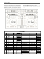
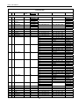
User Manual
Quark. User Manual
CONTENTS
1. CONTROLS AND CONNECTIONS .......................................................................................................................................................... 4
1.1. Top panel .......................................................................................................................................................................................... 4
1.2. Rear panel ........................................................................................................................................................................................ 4
1.3. Connections ...................................................................................................................................................................................... 4
2. SOFTWARE INSTALATION AND SETUP ............................................................................................................................................... 5
2.1. Virtual DJ .......................................................................................................................................................................................... 5
2.1.1. Virtual DJ LE installation ........................................................................................................................................................... 5
2.1.2. Virtual DJ LE updates ............................................................................................................................................................... 7
2.1.3. Virtual DJ Pro Configuration ..................................................................................................................................................... 8
2.2. Traktor............................................................................................................................................................................................... 8
3. FUNCTIONS AND CONTROLS ............................................................................................................................................................... 9
3.1. Virtual DJ .......................................................................................................................................................................................... 9
3.2. Traktor PRO 2 ................................................................................................................................................................................. 11
4. CONFIGURATION AND UPDATE.......................................................................................................................................................... 13
4.1. Firmware Version ............................................................................................................................................................................ 13
4.2. Firmware Update ............................................................................................................................................................................ 13
5. APENDIX ................................................................................................................................................................................................ 14
5.1. MIDI Specifications ......................................................................................................................................................................... 14
5.2. Technical specifications .................................................................................................................................................................. 18
1 Quark. User Manual
Intended to alert the user to the presence of
important
operation
and
maintenance
(servicing) instructions in the literature
accompanying this appliance.
The lightning flash with arrowhead symbol
within the equilateral triangle is intended to
alert the use to the presence of un-insulated
“dangerous voltage” within the unit.
CAUTION: TO REDUCE THE RISK OF ELECTRIC SHOCK, DO NOT REMOVE ANY COVER. NO USER-SERVICEABLE PARTS
INSIDE. REFER SERVICING TO QUALIFIED SERVICE PERSONNEL ONLY.
WARNING: TO PREVENT FIRE OR SHOCK HAZARD. DO NOT USE THIS PLUG WITH AN EXTENSION CORD, RECEPTACLE OR
OTHER OUTLET UNLESS THE BLADES CAN BE FULLY INSERTED TO PRESENT BLADE TO PREVENT FIRE OR SHOCK
HAZARD. DO NOT EXPOSE THIS APPLIANCE TO RAIN OR MOISTURE. TO PRVENT ELECTRICAL SHOCK, MATCH WIDE BLADE
PLUG TO WIDE SLOT FULLY INSERT.
not be blocked or covered. The openings should never be
blocked by placing the product on a bed, sofa, rug, or other
similar surface. This product should not be placed in a built-in
installation such as a bookcase or rack unless proper
ventilation is the manufacturer's instructions have been
adhered to.
SAFETY INSTRUCTIONS AND GUARRANTY
INFORMATION
1. Read Instructions. All the safety and operating instructions
should be read before this product is operated.
12. Any mounting of the product should follow the
manufacturer's instructions, and should use a mounting
accessory recommended by the manufacturer. The
manufacturer will NOT take responsibility for nonrecommended accessories.
2. Retain Instructions. The safety and operating instructions
should be retained for future reference.
3. Heed Warnings. All warnings on the appliance and in the
operating instructions should be adhered to.
4. Follow Instructions. All operating and use instructions should
be followed; failure to do so can void this guarantee.
13. Accessories. Do not place this product on an unstable cart,
stand, tripod, bracket, or table. The product may fall, causing
serious injury to a child or adult and serious damage to the
product. Use only with a cart, stand, tripod, bracket, or table
recommended by the manufacturer, or sold with the product.
5. Water and Moisture. The appliance should not be used near
water - for example, near a bathtub, washbowl, kitchen sink,
laundry tub, in a wet basement, or near a swimming pool, and
the like.
14. Lightning. For added protection for this product during a
lightning storm, or when it is left unattended and unused for
long periods of time, unplug it from the wall outlet and
disconnect the antenna or cable system. This will prevent
damage to the product due to lightning and power-line surges.
6. Carts and Stands. The appliance should be
used only with a cart or stand that is
recommended by the manufacturer. An
appliance and cart combination should be
moved with care. Quick stops, excessive
force, and uneven surfaces may cause the
appliance and cart combination to overturn. Wall or Ceiling
Mounting. The product should be mounted to a wall or ceiling
only as recommended by the manufacturer.
15. Replacement Parts: When replacement parts are required,
be sure the service technician has used replacement parts
specified by the manufacturer or have the same characteristics
as the original part. Unauthorized substitutions may result in
fire, electric shock, or other hazards.
7. Heat. The appliance should be situated away from heat
sources such as radiators, heat registers, stoves, or other
appliances (including amplifiers) that produce heat.
16. Use only cables in accordance with present standards, ask
your dealer.
17. Do not use right away the equipment in case has been
transported from a cold environment to a hot one. Moisture will
appear, let it off for a while.
8. Object and Liquid Entry. Care should be taken so that
objects do not fall and liquids are not spilled into the enclosure
through openings.
18. Cleaning. Do not use cleaning sprays where the controls
are. The appliance should be cleaned only as recommended
by the manufacturer. Clean by wiping with a cloth slightly damp
with water. Avoid getting water inside the appliance.
9. Damage Requiring Service. The appliance should be
serviced by qualified service personnel when:
A: The power-supply cord or the plug has been damaged; or
B: Objects have fallen, or liquid has been spilled into the
appliance; or
C: The appliance has been exposed to rain; or
D: The appliance does not appear to operate normally or
exhibits a marked change in performance; or
E: The appliance has been dropped, or the enclosure
damaged.
19. Audio ON: When installation is complete and you are about
to start using the unit. Before switching ON the unit DO lower
the Mains and Headphones volume controls. Failure to do so
can result in hearing injuries or amplification stage damage.
20. Safety Check Upon completion of any service or repairs to
this product, ask the service technician to perform safety
checks to determine that the product is in proper operating
condition.
10. Servicing. In accordance with E.U. directives the user shall
not attempt any service to the appliance beyond that described
in the operating instructions. All other servicing should be
referred to qualified service personnel. Failure to follow this
instruction can void this guarantee.
21. For AC line powered units - Before returning repaired unit
to user, use an ohm-meter to measure from both AC plug
blades to all exposed metallic parts. The resistance should be
more than 100,000 ohms.
11. Ventilation Slots and openings in the cabinet are provided
for ventilation and to ensure reliable operation of the product
and to protect it from overheating, and these openings must
22. To prevent fire or shock hazard. Do not use this plug with
an extension cord, receptacle or other outlet unless the blades
2 Quark. User Manual
can be fully inserted to present blade, match wide blade plug
to wide slot fully insert.
This product shall not be treated as
household waste. Instead it shall be handed
over to the applicable collection point for the
recycling of electrical and electronic
equipment. By ensuring this product is
disposed of correctly, you will help prevent
potential negative consequences for the
environment and human health, which could
otherwise be caused by inappropriate waste
handling of this product.
The recycling of materials will help to conserve natural
resources.
For more detailed information about recycling of this product,
please contact your local city office, your household waste
disposal service or the shop where you purchased the product.
TERMS OF USE
Your unit comes with a serial number sticked on it. Do not tear
the serial number; this can result in void guaranty.
SAFE AND EFICIENT USE
Select carefully the emplacement of the unit. Avoid placing it
under direct sun exposure. Avoid humid and damp places or
rough environments with excessive dust and vibrations and
excessive heat or cold. Also keep it away from humming
sources like the motors of whirl washers or transformers or
similar appliances.
No liquids must be close to the unit so that they can be spilled
on it. To completely disconnect the unit from you mains supply
unplug the plug of the adapter from the wall electric outlet.
The switch that controls the supply of electrical power to the
unit must be at easy reach in case is necessary a fast switch
off.
WARNING: do not place the unit in a closed environment
where is difficult to access the wall outlet.
Do not open the unit; it can cause personal injuries or the
damage of the equipment.
When unplugging the power supply cable of the adaptor from
the wall outlet, does not pull the cable. Take the plastic body of
the plug and unplug it.
Do not handle roughly the controls of the unit you can shorten
their lifespan.
Before moving the equipment, remember to unplug all cables.
Do not use chemical solvent to clean the unit. A dry and clean
cloth will do fine.
Safe this manual at reach so you can go back to the basic in
case you need it.
PRELIMINARY
Check the contents of the QUARK box and find the following
items:
1- Controller
1- Installation and instructions CD
1- Traktor Overlay
1- USB Cable (PC/MIDI)
1- Transformer AC/DC
FIRST STEPS
Equipment installation
Install the equipment on a stable and horizontal surface.
Avoid placing it under direct sun exposure humid and damp
places or rough environments.
Place the equipment as far away as possible of other audio
equipment as radios TVs etc.
3 Quark. User Manual
1. CONTRO
OLS AND CO
ONNECTION
NS
1.1. Top pan
nel
n
MIDI notes are sent through ddifferent MIDI channels upon
election; FX or SP.
S LEDs statuss are refreshed by firmware.
se
5. Multimode kno
obs and encodeer with 3 modes
s for each deck..
Ea
ach control will be able to sennd 3 different MIDI
M
notes upon
n
mo
ode selection. Each
E
mode has a button colourr associated.
6. Central mixer with
w 3 band equualizer with kill. On this section
n
als
so are controllable the functionns; gain for each
h channel, faderr
vo
olume, crossfade
er and mains ouutput level.
1. Controls Diistribution for an
a optimal use of Virtual DJ a
and
Traktor.
AY and SYNC buttons are rubber for long
ger
2. CUE, PLA
lifespan.
ugh
3. Control of up to 4 Decks. MIDI notes are sent throu
ECK A/B or C
C/D.
different MIDI channels upon selection; DE
LEDs status arre refreshed by firmware.
4. 8 potentiom
meters/buttons independent of
o deck status to
control effectss and/or sample
es. All can control two functio
ons.
1.2. Rear panel
QU
UARK is conne
ected to a hub (w/out external supply) or anyy
other device una
able to supply QUARK with enough powerr
(current/voltage).
o turn ON/OFF tthe unit.
Prress POWER to
ply
1. Power supp
Connect the un
nit to your comp
puter through the USB connecttor.
Connect the p
power supply unit to QUARK connector DC IN.
QUARK can w
work only with th
he computer po
ower through US
SB.
The external p
power supply unit
u
will only be
e necessary wh
hen
1.3. Connecttions
4 Quark. User Manual
NO
OTE: Use only the supplied caables for power supply through
h
ex
xternal adapter or USB to coomputer. Manuffacturer cannott
take responsibilitty for any dam
mage caused by
b use of non-ho
omologated cables.
ATTENTION. Always unplug
g the unit before connecting tthe
r
in equipment damage.
signal cables, otherwise can result
1. If you need to change the signal connecttor first unplug tthe
unit from the power supply; Either the USB or the exterrnal
adapter.
2. SOFTWA
ARE INSTAL
LATION AND
D SETUP
an start using Akiyama
A
QUARK you will need
d a
Before you ca
DJ Software. W
We will explain how to install Virtual DJ LE a
and
how to configu
ure Virtual DJ LE, Virtual DJ PRO and Trakktor
PRO 2.
2.1. Virtual D
DJ
pose built Virtua
al DJ LE for QU
UARK. In case yyou
There is a purp
have a licen
nse for Virtua
al DJ PRO the software w
will
automatically identify QUARK
K. We will go thrrough the differrent
e Virtual DJ LE
E and PRO to be
steps to install and configure
QUARK.
controlled by Q
DJ LE installation
2.1.1. Virtual D
Note: You musst uninstall any Virtual DJ LE you had installed
d in
your PC beforre you install th
he Virtual DJ LE
E (Quark) versi on.
There can be o
only one Virtual DJ LE installed
d in each PC.
Windows Insttallation
Se
elect the accept box and press “Next”.
Execute the Viirtual DJ LE file clicking the icon
install_virtualdjj_le_vx.y.z.msi where x.y.z is the softwa
are
version. Installation will startt with welcome window as se
een
below.
ype of installatio
on is selectable;; we recommend you start with
h
Ty
“T
Typical”. If in la
ater installation you need to select
s
concrete
e
un
nits to install you
u shall use “Cusstom” option.
Select “Next” to start insttallation. Follow
wing the licen
nse
agreement willl show up.
Prress “Install”, ins
stallation will staart.
5 Quark. User Manual
elect “Continue
e” to start innstallation. Following license
e
Se
ag
greement window will pop up.
m is installed you can choose to
o launch it or e
exit.
Once program
Select “Launch
h VirtualDJ” to start
s
it.
Se
elect “Agree” an
nd continue withh installation wiz
zard.
The first time yyou run the prog
gram a window will require you
u to
fill up the seria
al number that iss supplied with your QUARK (ffind
it at the label o
of the supplied CD). Fill it and press OK. Virttual
DJ LE for QUA
ARK will open:
Fo
ollowing will app
pear a window sshowing the typ
pe of installation
n
to choose. You ca
an change/selecct the folder where it will reside
e
the software, or press
p
“Install” to commence at once.
o
MAC Installation
Execute the Viirtual DJ LE file clicking the icon
are
install_virtualdjj_le_vx.y.z.pkg where x.y.z is the softwa
version. Installation will startt with welcome window as se
een
below.
6 Quark. User Manual
g changes at th
he installation wizard
w
you shalll fill
For introducing
your name and
d password.
st time you run the software a w
window as seen
n below will pop
p
Fis
up
p. Fill up serial number provideed with your QU
UARK (find it att
the label of the su
upplied CD) andd then click OK.
Meanwhile Virttual DJ LE is in process of install you will see tthe
following windo
ow.
Fo
ollowing Virtual DJ LE for QUAR
RK will open:
2.1.2. Virtual DJ LE updates
o update your so
oftware follow thhe steps:
To
-O
Open web page:
<h
http://www.virtua
aldj.com/downlooad/updates.htm
ml>.
Th
his is VirtualDJ download
d
page..
- Register
R
or fill user name and ppassword to acc
cess download..
On
nce you acces
ss your accounnt you will see
e a window ass
be
elow:
When install is complete and
a
successful you will see
e a
een below.
message as se
7 Quark. User Manual
2.1.3. Virtual DJ Pro Configuraation
w automaticallyy recognise QU
UARK controller..
Virtual DJ PRO will
Th
herefore you will only have to co
configure the sound card.
2.2. Traktor
y will find an Overlay purpos
se designed forr
Att QUARK box you
TR
RAKTOR 2 with
h QUARK. Al coontrols functions
s correspond to
o
the MIDI map that you can find aat your CD at QU
UARK box.
Th
hese maps are set to work withh 4 Decks. Dec
cks A and B willl
be
e TRACK DECK
K type and Deccks C and D will
w be SAMPLE
E
DE
ECK type.
To
o load these files (MIDI mapss) at your TRA
AKTOR 2 go to
o
Prreferences/Conttroller Manager and press Impo
ort.
me.
- Click at (clickk here) to registter your software for the first tim
At following up
pdates you will directly
d
be directed to last pointt.
- Next you will see the wind
dow below, fill it with your se
erial
number typed at your CD.
name QUARK will
w show up. At this page you ccan
- An icon with n
find the availa
able updates fo
or QUARK. Do
ownload from tthis
page.
s you press Imp
port a window w
with a Browser will
w appear then
n
As
yo
ou can select the
e tsi file at the foolder where you
u have the MIDII
MA
APS.
8 Quark. User Manual
3. FUNCTIO
ONS AND CO
ONTROLS
3.1. Virtual D
DJ
SAMPLERS
1. EFECTOS/S
The controls iincluded in thiss region can be used to conttrol
EFFECTS (FX
X) as well ass SAMPLERS (SP). It can be
switched betw
ween these two
o modes by pressing the butt
tton
above FX/SP L
LED:
2. SHIFT
Th
he Shift Button provides a secoond MIDI layer for
f the selected
d
de
eck.
-P
Press the button
n labelled with a bin (3) while keeping SHIFT
T
prressed to make
e SHIFT remainn activated eve
en when SHIFT
T
bu
utton is released
d. Press the buttton labelled with a bin again to
o
de
eactivate SHIFT
T.
FX MODE:
ers of effects ca
an be adjusted by turning P1 a
and
-Two paramete
P2 knobs.
Y knob to chang
ge the song's ke
ey. Push it to lo
ock
-Turn the KEY
the key.
e and reset Filte
er.
-Use the Filter knob to change
-Use the butto
ons to select on
ne effect (
) and activate
e it
(ACTIVE).
ntrols modify the
e effect of the selected
s
deck (ssee
NOTE: FX con
point 4).
P
3. MULTIMODO HOTCUE/LOOP
Th
he round button provides one M
MIDI layer for ea
ach mode for alll
the controls inside the box labellled with a 3. Ch
hange from one
e
ode to another by pressing it.
mo
-A
Adjust the loo
op size by turning the encoder and
d
ac
ctivate/deactivatte the loop by prressing it.
-P
Press SHIFT+ tu
urn encoder to move the loop the same size
e
the loop has.
Under Video mo
ode turn the eencoder to sele
ect a Transition
n
-U
(deck L) or an Effect (deck R). Press th
he encoder to
o
ac
ctivate/deactivatte the Transitionn or Effect.
-U
Under Video mo
ode press SHIFT
ncoder to adjustt
T + turn the en
the loop size.
SP MODE:
8 is
-Play/Pause a sample by presssing a knob. Each knob S1/S8
associated with
h one sample.
-Turn the knob
b to adjust the vo
olume of the sample.
-Start/Stop re
ecording a sa
ample by pres
ssing the butt
tton
corresponding to the sample number. The active
a
deck will be
recorded.
witch between lo
ooped or one-s hot
-Press SHIFT + button to sw
mode.
OT CUE (round
d button unlit):
HO
-A
A hot cue can be
b set and stoored by pressing any of the 6
nu
umbered cue buttons if the sselected cue slo
ot is free (unlitt
LE
ED).
9 Quark. User Manual
-Press any cue buttons, which have a cue point stored, to
trigger the stored cue.
-Hot cues can be deleted by pressing the cue button while
holding the button labelled with a bin.
-Press SHIFT + HOT CUE 1 to activate/deactivate Smart Hot
Cue.
-A yellow lit button means that there is a hot cue saved.
7. TEMPO
-Use the Pitch Fader to control the deck's tempo.
-Use the Pitch Bend buttons for pitch bending.
-Tempo Range can be selected by pressing SHIFT + pitch
bend (-).
-Reset the tempo by pressing SHIFT + pitch bend (+).
8. TRANSPORT
-Press Play/Pause button to Start/Stop playback of deck.
-Press SHIFT + Play/Pause to skip to the first beat of the track.
-If song is paused, set a new cue point or if you are in the cue
point position play the track from the cue point by pressing the
CUE button and return to cue point when released. If song is
playing, press CUE to pause the reproduction and jump to the
last cue point.
-Use SHIFT + CUE to activate/deactivate Smart Play.
-Use the SYNC button to match the BPMs of different tracks.
-Press SHIFT + SYNC to set to master the deck in which it has
been pressed.
AUTO LOOP (round button orange):
-An autoloop is set by pressing any of the 6 numbered buttons.
The autoloop size depends on the pressed button and can be
set from 1 to 32 beats.
-The autoloop is deactivated by pressing the button
corresponding to the actual size.
-Change the loop size by pressing a button which has
associated a size different than the actual active loop size.
-Press SHIFT + HOT CUE 1 to activate/deactivate Smart
Loop.
-In this mode all buttons will light orange. The button
corresponding to the active loop size will blink.
9. MIXER
-Tweak the sound using the 3-Band EQ
-Turn the MASTER knob to adjust the volume of the master
signal.
-Adjust the deck volume by turning the gain knob.
-Select the deck that must be pre-listened by pressing the
Monitor buttons (labelled with headphones).
-Press SHIFT + Monitor button to select the beat of the
working deck which will be shown in front in the display.
-Use the Linefader and Crossfader for mixing.
-Use AUTO buttons to automatically crossfader to the other
deck.
-Under Video mode press LINK to link or unlink the video
crossfader to the audio crossfader.
-Under Video mode use AUTO to move the video crossfader
automatically.
LOOP ROLL (round button green):
-An autoloop is set by pressing any of the 6 numbered buttons.
The autoloop size depends on the pressed button and can be
set from 1/32 to 1 beat. The loop will be active only while the
button is hold.
-Press SHIFT + HOT CUE 1 to activate/deactivate Smart
Loop.
-In this mode all buttons will light green. The button
corresponding to the active loop size will blink.
4. DECK SELECT
Switch between decks A/C and decks B/D.
5. LOOP
-Set the starting point of a loop by pressing IN button.
-Press OUT button to set the ending point of the loop.
-Press RELOOP to jump to the starting point of the loop. If loop
is not activated, the last set loop will be activated.
-Press SHIFT + IN to enter in a mode in which the starting
point of the loop can be modified, IN ADJUST. The IN button
will blink while this mode is active. Turn the jog wheel to modify
the starting point. Press SHIFT + IN to exit from the mode. If
this mode is active but there is not any loop active, the last set
loop will be activated when the jog wheel is turned.
-Press SHIFT + OUT to enter in a mode in which the ending
point of the loop can be modified, OUT ADJUST. The
performance of this mode is equivalent to the IN ADJUST
mode but in this case the ending point is adjusted.
-Enter to MOVE LOOP mode by pressing SHIFT + RELOOP.
Performance is similar to IN/OUT ADJUST but in this case
loop can be moved..
10. BROWSER
-Turn the encoder to scroll through the songs.
-Press SHIFT + turn the encoder to scroll through the folders.
-Load the song to the active deck by pressing LOAD buttons.
-Press the encoder to open or close the subfolders of the
selected folder (when focus is on folders).
-Press SHIFT + encoder to open or close the subfolders of the
selected folder (when focus is on folders).
-Switch the mixer section between mixer and video by pushing
VIDEO MODE.
6. JOGWHEEL
Press SCRATCH button to toggle the wheel mode between
CDJ and Vinyl.
-Use the jog wheel to scratch or modify the pitch bend.
-Use SHIFT + jog wheel to search through the track
-Under Video mode press SHIFT + turn jog wheel to adjust the
parameter of the effect
10 Quark. User Manual
3.2. Traktorr PRO 2 hift (SGL): Sele
ects the next effe
fect on the list.
Sh
- FX
F 3:
SG
GL: Adjusts the Parameter 3 off the selected efffect.
GR
RP: Adjusts the level of the effeect 3.
- FX
F BUTTON 2:
SG
GL: function upo
on selected effeect ON/OFF.
GR
RP: effect 3 ON
N/OFF.
Sh
hift (GRP): Sele
ects the next efffect on the list.
1. FX MODE.
P modes.
There is SINGLE and GROUP
GLE (SLG) we modify different parameters o
of a
In mode SING
given effect. In
n mode GROUP
P (GRP) we mod
dify one parame
eter
of each of the tthree effects we
e can use in tog
gether.
- SGL: Change
es to GROUP mode.
m
- GRP: Change
es to SINGLE mode.
m
- DRY/WET:
he amount of pro
ocessed signal (by
SGL and GRP: Determines th
nal that will be played.
p
the effect) verssus original sign
- FX ON:
dule.
SGL: ON/OFF the effects mod
Shift (SGL): S
Selects the next effect on the lis
st.
- FX 1:
d effect.
SGL: Adjusts tthe Parameter 1 of the selected
GRP: Adjusts tthe level of the effect 1.
- FX RESET:
o the original (m
manufacturer) co
onfiguration.
SGL: Return to
Shift (SGL): S
Selects the previious effect on th
he list.
GRP: effect 1 O
ON/OFF.
Shift (GRP): S
Selects the next effect on the lis
st.
- FX 2:
SGL: Adjusts tthe Parameter 2 of the selected
d effect.
GRP: Adjusts tthe level of the effect 2.
- FX BUTTON 1:
SGL: function upon selected effect
e
ON/OFF.
ON/OFF.
GRP: effect 2 O
2. SHIFT.
SH
HIFT button du
uplicates the fu nctions of the controls of the
e
de
eck. There are tw
wo modes:
- SHIFT
S
is active while the buttonn is pressed.
- To engage pe
ermanently SH IFT mode press SHIFT and
d
DE
ELETE while keeping SHIFT pressed. To re
eturn to normall
Sh
hift mode press DELETE againn.
SH
HIFT button will light when shiftt is engaged.
Ea
ach Deck has a SHIFT buttonn. SHIFT button of right deckk
on
nly affects the controls of righht deck. SHIFT
T button of leftt
de
eck only affects the controls of lleft deck.
CK).
3. PLAY SAMPLE (TRACK DEC
- S 1: plays samp
ple at slot 1.
Sh
hift: Switches between the twoo possible sizes of the Deck.
- S 2: plays samp
ple at slot 2.
11 Quark. User Manual
B
1 - 4:
- BUTTON
SE
ELECT SLOT: Select
S
slot 1-4.
DE
ECK LOAD: Loa
ads the loop froom the deck to slot
s 1-4.
Sh
hift: Loads the loop from the oppposite deck.
LIST LOAD: Load
ds the loop from
m the tracks list to
t slot 1-4.
hift: Loads the loop from the LLOOP RECORDER section to
o
Sh
slo
ot 1-4.
- BUTTON
B
5:
SE
ELECT SLOT: All
A slots from onne deck are sele
ected at once.
DE
ECK LOAD: No function.
LIST LOAD: No fu
unction.
B
6:
- BUTTON
SE
ELECT SLOT: While
W
the buttoon is pressed all Samples of a
giv
ven deck will ac
ctivate.
DE
ECK LOAD: No function.
LIST LOAD: No fu
unction.
A
Turning
T
the conntrol we set the Slot volume..
- AUTOLOOP:
Prress the control to silence the sslot.
Th
he LED light when the slot is m uted.
Sh
hift: Turning the control we aadjust the filter at the selected
d
Slot. Pressing the
e control the filteer is turned off.
Shift: Shows/h
hides Advanced
d Panel.
- S 3: plays sample at slot 3.
Shift: Waveforrm Zoom IN.
- S 4: plays sample at slot 4.
Shift: Waveforrm (Zoom OUT..
PLE (SAMPLE DECK).
3. PLAY SAMP
- S1 - S4: R
Records at the
e tracks list th
he sample of tthe
corresponding slot.
DE (TRACK DEC
CK).
4. MULTIMOD
- SELECT MO
ODE:
etween the thre
ee possible mod
des
The round buttton switches be
of the advance
ed panel (CUE/M
MOVE/GRID).
The function o
of the multimode
e buttons, knobs and encoder w
will
change upon the selected mo
ode.
- DELETE ( ):
Delete Cue po
oints. Press DELETE buttons and
a also press tthe
Hot CUE butto
on you want to delete. Delete function is acttive
only in CUE mode.
nent mode.
Shift: Enabless Shift in perman
- BUTTON 1:
CUE: Hot cue 1
Shift: Memorizzes a cue/Loop at the first available cue point.
MOVE: Selectts track move mode.
m
With this
s button we sellect
Move Mode.
ards.
GRID: Displaces Grid backwa
- BUTTON 2:
CUE: Hot cue 2
Shift: no functtion.
MOVE: Selectts track move mode.
m
With this
s button we sellect
next Move Mod
de option.
GRID: Displaces Grid forward
d.
- BUTTON 3:
CUE: Hot cue 3
p
Shift: Jumps to the next cue point.
MOVE: Selectss the movement size.
GRID: BPM fin
ne tuning.
- BUTTON 4:
CUE: Hot cue 4
c point.
Shift: Jumps to the previous cue
MOVE: Selectss the movement size.
GRID: BPM fin
ne tuning.
- BUTTON 5:
CUE: Hot cue 5
ous
Shift: Select Cue point type from a list. Choose previo
option at the lisst.
MOVE: Movess playback pointt backwards.
GRID: Grid auttomatic adjust.
- BUTTON 6:
CUE: Hot cue 6
Cue point type from
f
a list. Choose next option
n at
Shift: Select C
the list.
MOVE: Movess playback pointt forward.
GRID: Tempo automatic adjusst.
- AUTOLOOP:: Turn the contro
ol to select loop
p size. Press to set
the loop. The L
LED blinks when a loop is set.
Shift: Turn the
e control to movve the loop throu
ugh the track. T
This
function operattes only when a loop is playing
g.
4. MULTIMOD
DE (SAMPLE DE
ECK).
- SELECT MO
ODE: The roun
nd button switc
ches between tthe
three possible modes of Samp
ple Deck:
SELECT SLOT
T: This mode is for activating th
he different Slotts.
When a slot is active we ca
an perform som
me actions upon
n it
g, scratch, pitch
hbend, play/pause and others).
(volume setting
DECK LOAD: On this mode we
w can load loops from Deck A or
B. First you ha
ave to select the
e slot where to load the loop w
with
SELECT SLOT
T.
LIST LOAD: O
On this mode we
w can load loops from a listt of
songs/tracks or loops or the loops from
f
the LOO
OP
RECORDER.
- DELETE ( ):
ed on the select
cted
On this mode we can delete the loop loade
slot.
Shift: Engagess SHIFT permanently.
TRACK DECK)).
5. TRANSPORT/JOG WHEEL (T
- PLAY/PAUSE:
P
Start/Stop
S
playbback.
Sh
hift: Skips to the
e track beginninng.
- CUE:
C
Skips to th
he last Cue set.
- SYNC:
S
Synchronizes the BPM vvalue with the BPM
B
master.
Sh
hift: MASTER Function. Seleccts which deck
k is the masterr
tempo.
OFF “loop activve” function. This
T
function iss
- ACTIVE: ON/O
au
utomatically activated each timee we set an Auttoloop or a loop
p
with IN/OUT butto
ons.
- IN: Sets the beg
ginning of a loopp.
N ADJUST: Mea
anwhile you presss the button use the wheel to
o
IN
ad
djust the starting
g point of loop. LLoop must be playing.
- OUT:
O
Sets the end
e of a loop.
OU
UT ADJUST: Meanwhile
M
you ppress the button
n use the wheell
to adjust the end point of loop. Looop must be pla
aying.
- PITCH
P
FADER: Adjusts the tem
mpo of the deck.
- PITCHBEND: Adjusts
A
the tem
mpo of the deck
k while buttonss
en released tem
mpo return to original value.
arre pressed. Whe
Sh
hift: Assigns FX
X1 and FX2 moddules to each de
eck.
- SCRATCH
S
( ):
) ON/OFF SCR
RATCH mode.
Sh
hift: Changes pitch range uponn the given values.
- DECK:
D
Selects SAMPLE
S
DECK
K (C/D).
- JOG
J
WHEEL: Turn the wheel too adjust the dec
ck tempo.
SC
CRATCH: Turn to perform scraatch when SCR
RATCH mode iss
ON
N.
LO
OOP ADJUST: Turn
T
the wheel to adjust start and
a end point off
a loop pressing buttons IN/OUT.
hift: Fast move through a trackk.
Sh
SAMPLE DECK
K).
5. TRANSPORT/JOG WHEEL (S
- PLAY/PAUSE:
P
Start/Stop
S
playbback of selected
d slot.
- CUE: Toggles between simpple play and loop play of the
e
sa
ample.
- SYNC:
S
Synchronizes the BPM vvalue of the acttive slot.
- IN: sample size is halved.
O
sample siz
ze is doubled.
- OUT:
- ACTIVE:
A
sets sa
ample size to orriginal value.
- PITCH
P
FADER: Sets the tempoo of the active slot.
- PITCHBEND:
P
Adjusts
A
the temppo of the sample while buttonss
arre pressed. Whe
en released tem
mpo return to orriginal value.
Sh
hift: Assigns FX
X1 and FX2 moddules to each de
eck.
- SCRATCH
S
(
): Pressing thee buttons the selected sample
e
pla
ayback stops. If we turn the w
wheel with the button pressed
d
we
e have scratch effect.
e
- DECK:
D
Selects TRACK
T
DECK ((A/B).
- JOG
J
WHEEL: turn
t
the wheel tto set the temp
po of the active
e
slo
ot.
SC
CRATCH: press
s/hold the buttonn to enable scra
atch effect.
6. MIXER/EQ.
- HIGH:
H
turn to control
c
the highh frequencies and
a
mutes/KILL
L
them when pressed, LED will lighht when mute is
s on.
12 Quark. User Manual
Shift: Press to
o activate the FILTER and turn to adjust it.
- MID: turn to ccontrol the mid frequencies
f
and
d mutes/KILL th em
when pressed,, LED will light when
w
mute is on
n.
Shift: Press to
o activate the KE
EY LOCK and tu
urn to adjust KE
EY.
- LOW: turn tto control the low
l
frequencies
s and mutes/K
KILL
them when pre
essed, LED will light when mute
e is on.
Shift: turn to a
adjust PAN funcction.
- GAIN: turn to
o adjust channell Gain.
- AUTO: Presss and there iss an automatic crossfade to tthe
selected side ((Left/Right).
Shift: Assigns crossfade Left or Right to each
h of the 4 deckss.
4.. CONFIGUR
RATION AND
D UPDATE
4.1. Firmware Version
V
ollow the steps to view thee firmware ve
ersion currentlyy
Fo
ins
stalled.
- Turn
T
OFF the Controller.
- Press/hold
P
Righ
ht channel Headdphones button while you Turn
n
ON
N the Controllerr.
- Vu-meter
V
LEDs will show firmw
ware version un
ntil you depresss
the button.
v
is 2.3, ttwo LEDs at Le
eft LED bar willl
e.g.: if firmware version
ght and 3 LEDs at Right LED baar will light..
lig
7. LOOP RECORDER.
ORDER: Presss to engage LO
OOP RECORD ER
- LOOP RECO
mode. The buttton will light.
- DRY/WET: Determines th
he amount of processed sig
gnal
oop
versus originall signal that will be recorded. Press to select lo
size.
C function on LO
OOP RECORD ER
- REC: Press to engage REC
he loop size is surpassed
s
the REC
R
function is not
mode. Once th
active anymore
e.
- PLAY/PAUSE
E: PLAY/PAUSE function in LO
OOP RECORD ER
mode.
E function. Erasses the loop cre
eated under LOO
Shift: DELETE
OP
RECORDER.
4.2. Firmware Update
U
ollow the steps to
t Update Firmw
ware:
Fo
No
ote: only possib
ble to update frrom a computer with Windowss
O..S.
- Turn
T
OFF the Controller
C
and cconnect it throug
gh USB to yourr
co
omputer.
- Press/Hold
P
VIDE
EO MODE buttoon.
- Turn
T
ON the Controller while VIIDEO MODE bu
utton is pressed
d
- Depress
D
the button when it lightts up.
- It
I will appear in
n your computeer a new mass storage device
e
na
amed QUARK Disk.
D
OWSER.
8. MIXER/BRO
- MASTER: sets the main outp
put level or volu
ume.
der to browse th
hrough your listt of
- BROWSER: Turn the encod
Press to enlarge
e the browser window.
w
songs/tracks. P
Shift: Turn the
e encoder to brrowse through your
y
list of folde
ers.
Press to open//close the folderrs.
OP
- LOOP RECORDER: Pre
ess button to activate LOO
mode.
RECORDER m
Shift: Toggless vu-meter view mode. In first case
c
vu-meters w
will
show Left chan
nnel level and Right
R
channel level respectivelyy.
Second press and vu-meters will show MAST
TER stereo outtput
level.
- LOAD A/B:
Loads selected
d track to selectted Deck.
- MONITOR CUE LEFT (
)::
dphones.
Pre-listen Left channel at head
unction ON/OFF
F.
Shift: SNAP fu
- MONITOR CUE RIGHT (
):
ht channel at he
eadphones.
Pre-listen Righ
Shift: QUANTIZE function ON
N/OFF.
Copy the file corresponding to thhe firmware you
u wish to load in
n
-C
the new disk (Qua
ark Disk).
When firmware update is finishh all LEDs of QUARK
Q
will lightt
-W
up
p.
-R
Reboot the controller before using it with
h the updated
d
firmware.
13 Quark. User Manual
5. APENDIX
ACTION: here we have the action value. The different values
that can attain are explained at parts a) and e).
Note: the MIDI MAP is presented in hexadecimal base >
NOTE or CC. To assign physical control to software functions
you need to translate the MIDI MAP into decimal base.
Following, we explain have to find out this equivalence HEXDEC:
5.1. MIDI Specifications
A DJ Software have the “mapping” function that assigns MIDI
messages to the different functions of the DJ Software.
We also have to match the DJ Software functions with the
controls of the external device (the controller). We do so by
assigning the DJ Software function and the control the same
MIDI note or message.
Each of QUARK controls generates various MIDI messages
you can see at table QUARK MIDI MAP. We can send the
MIDI messages through channels 1 to 16, this is a MIDI
standard. We can see three different parts on a MIDI message:
- The MIDI code (MIDI CODE) lets us know what type of
message is sent.
- The FUNCTION CODE gives us the note or control value.
- The action let us know the value that the control attains when
is manipulated.
At the table we have a column for each of the three parts of a
MIDI message. The controls are grouped upon their in type so
also upon their MIDI code.
DJ Software’s use two types of MIDI codes:
- “Control Note” (switch): the control is a switch (you see a
button) or a LED and will look like NOTE C2. Each note has a
number that at the table is expressed in Hexadecimal (HEX).
Further on at this manual we will explain how notes and
numbers correspond to each other and how to change from
hexadecimal to decimal. In this case MIDI CODE is 9 and
FUNCTION CODE is the note of the control.
- “Control Change” (CC): the control will be a potentiometer or
encoder and will have a label like Cc53. In this case MIDI
CODE is B and FUNCTION CODE is a value between 0 and
127. We will associate a value to each control of the kind.
Upon the value of the action part of the MIID message we will
classify the controls as follows:
a- NOTE-KEY: are note type messages. Action value can be
127 (7FH) when we press or 0 when we release.
b- NOTE-LED: determines the LED that will light, are note type
messages as the switches and the values are 127 for LED ON
and 0 for LED OFF. In the LEDs case it is the DJ Software that
sends the MIDI messages to the controller.
c- CC-ABSOLUTE (VR) - CC “Control Change” Absolute.
These are potentiometer like controls. The action value is a
number between 0 an 127 upon the potentiometer position.
d- CC-RELATIVE (ENCODER/WHEEL) - CC “Control Change”
Relative. These are encoder like controls. As oppose to the
potentiometer that encoder does not send a message to report
its position but only report changes when turning to clockwise
or anticlockwise. It is sent the value 63 (3FH) if it turns to the
left and 65 (41H) if it turns to the right.
e- CC-LEVEL LED. The value sent in the action from 0 to 127
will tell how many LEDs are to be turned ON at the vu-meter.
At the before last column on the table you can find in the
compressed way the values that each action can attain. There
are DJ Software’s where it is not necessary know note values
or control values because this software “read” them
automatically. That is called the “Learn mode” where by
touching a control it assigns its note to a certain function
selected by the user.
At other software you have to wright manually the values or for
the LEDs at any software you have to do the writing because
there is no Lear mode for exiting MIDI messages (i.e. LEDs).
Therefore we recommend you try understanding the meaning
and workings of the table QUARK MIDI MAP.
Following, we explain the columns of the MIDI MAP:
FUNCTION: here find the name of the control of QUARK as
seen on its printing.
MIDI CODE: indicates if the message is a Control Note (9) or
Control Change (B).
CHANNEL+MIDI CODE: appears MIDI CODE values with the
channel (minus 1) used to send the message. Forward in this
manual we explain the MIDI channels used at QUARK.
FUNCTION CODE: at this column we have the value of the
note.
0H
1H
2H
3H
4H
5H
6H
7H
8H
9H
AH
BH
CH
DH
EH
FH
1H
16
17
18
19
20
21
22
23
24
25
26
27
28
29
30
31
2H
32
33
34
35
36
37
38
39
40
41
42
43
44
45
46
47
3H
48
49
50
51
52
53
54
55
56
57
58
59
60
61
62
63
4H
64
65
66
67
68
69
70
71
72
73
74
75
76
77
78
79
5H
80
81
82
83
84
85
86
87
88
89
90
91
92
93
94
95
6H
96
97
98
99
100
101
102
103
104
105
106
107
108
109
110
111
7H
112
113
114
115
116
117
118
119
120
121
122
123
124
125
126
127
8H
128
129
130
131
132
133
134
135
136
137
138
139
140
141
142
143
9H
144
145
146
147
148
149
150
151
152
153
154
155
156
157
158
159
AH
160
161
162
163
164
165
166
167
168
169
170
171
172
173
174
175
BH
176
177
178
179
180
181
182
183
184
185
186
187
188
189
190
191
CH
192
193
194
195
196
197
198
199
200
201
202
203
204
205
206
207
DH
208
209
210
211
212
213
214
215
216
217
218
219
220
221
222
223
EH
224
225
226
227
228
229
230
231
232
233
234
235
236
237
238
239
FH
240
241
242
243
244
245
246
247
248
249
250
251
252
253
254
255
To translate a Hexadecimal base number into a Decimal base
we have to:
- find the column that has the number that appears at the left.
- find the row that has the letter that accompanies the number.
- the convergence of row and column is the equivalent DEC
number.
Inversely to translate an DEC base number into a Hex base we
have to:
- find the number at the table. Its column is the first hex digit,
the second hex digit is it row.
E.g. Play control MIDI address is 34. Find the DEC
equivalence at the Hexa-Dec table: Column 3 / Row 4 it is
decimal number 52.
Some softwares require not only know the decimal value but
also the corresponding note (for control change the decimal
number is enough). We can perform the Note-Decimal number
equivalence using the following table:
Octave #
-1
0
1
2
3
4
5
6
7
8
9
C
0
12
24
36
48
60
72
84
96
108
120
C#
1
13
25
37
49
61
73
85
97
109
121
D
2
14
26
38
50
62
74
86
98
110
122
D#
3
15
27
39
51
63
75
87
99
111
123
Note Numbers
E F F# G
4
5
6
7
16 17 18 19
28 29 30 31
40 41 42 43
52 53 54 55
64 65 66 67
76 77 78 79
88 89 90 91
100 101 102 103
112 113 114 115
124 125 126 127
G#
8
20
32
44
56
68
80
92
104
116
A
9
21
33
45
57
69
81
93
105
117
A#
10
22
34
46
58
70
82
94
106
118
B
11
23
35
47
59
71
83
95
107
119
To find the note associated to a decimal number just take the
column where the number is as the note and the row is the
octave. Following the example presented before the
corresponding note to Play button is E3.
As seen at FUCTION CODE column of the MIDI table, each of
the controls of QUARK can send two different messages upon
the state of the Shift button. Remember we can permanently
engage Shift.
QUARK can be divided is 5 parts and the controls that fall in
each of these parts are sent through a different MIDI channel.
The central part of the controller has the controls to be sent
through channel 5.
There are two areas that are not dependent upon Deck
selection. These areas are devised to control effects and
14 0H
0
1
2
3
4
5
6
7
8
9
10
11
12
13
14
15
Quark. User Manual
messages throug
gh channels 1 aand 3 and controls at the rightt
de
eck will send me
essages throughh channels 2 an
nd 4.
Att the following ta
able find the tabble comprising all
a explained up
p
to now.
samples. Presss FX/SP button
n and the MIDI messages will be
sent through tw
wo different cha
annels, 6 and 7 for the controlss at
the left side of the controller and
a 8 and 9 for the controls at tthe
right side of the
e controller.
Finally there a
are two more areas
a
correspon
nding to Deck L
Left
and Deck Rig
ght. The contrrols at the lefft deck will se
end
Q
QUARK MIDI MAP
M
I/O
FUNCTION
MIDI
CODE
CHANNEL+
+
MIDI CODE
E
FUNCTIO
ON CODE
1
I
S1/P1
9
01H/41H
H(SHIFT ON)
7FH:ON
N/00H:OFF
2
I
S2/P2
9
02H/42H
H(SHIFT ON)
7FH:ON
N/00H:OFF
3
I
S3/KEY
9
03H/43H
H(SHIFT ON)
7FH:ON
N/00H:OFF
4
I
S4/FILTER
9
04H/44H
H(SHIFT ON)
7FH:ON
N/00H:OFF
5
I
DECK
9
07H
7FH:ON
N/00H:OFF
6
I
SLOT
9
08H
7FH:ON
N/00H:OFF
7
8
9
10
11
12
13
14
15
16
I
I
I
I
I
I
I
I
I
I
HI
MID
LOW
SHIFT
DELETE
</REC1
>/REC2
ACTIVE/REC3
3
REC/REC4
HOT CUE 1
9
9
9
9
9
9
9
9
9
9
9X (X=5,7)
9X (X=6,8)
9X (X=5,7)
9X (X=6,8)
9X (X=5,7)
9X (X=6,8)
9X (X=5,7)
9X (X=6,8)
9X (X=0,2)
9X (X=1,3)
9X (X=5,7)
9X (X=6,8)
9X
9X
9X
9X
9X
9X
9X
9X
9X
9X
7FH:ON
N/00H:OFF
7FH:ON
N/00H:OFF
7FH:ON
N/00H:OFF
7FH:ON
N/00H:OFF
N/00H:OFF
7FH:ON
7FH:ON
N/00H:OFF
7FH:ON
N/00H:OFF
7FH:ON
N/00H:OFF
7FH:ON
N/00H:OFF
7FH:ON
N/00H:OFF
17
I
HOT CUE 2
9
9X
0AH/4AH(SHIFT ON)
0BH/4BH(SHIFT ON)
0CH/4C
CH(SHIFT ON)
3FH
16H(SHIF
FT NOT PRESS
S)
0EH/4EH(SHIFT ON)
0FH/4FH
H(SHIFT ON)
10H/50H
H(SHIFT ON)
11H/51H
H(SHIFT ON)
17H/57H
H(SHIFT ON)
18H/58H
H(SHIFT ON)
19H/59H
H(SHIFT ON)
1AH/5AH(SHIFT ON)
ACTION
KEY
15 7FH:ON
N/00H:OFF
SLOT=1,2
SLOT=3,4
SLOT=1,2
SLOT=3,4
SLOT=1,2
SLOT=3,4
SLOT=1,2
SLOT=3,4
DECK=A,C
DECK=B,D
SLOT=1,2
SLOT=3,4
NORMAL
AUTOLOOP
P
LOOP ROLL
L
NORMAL
Quark. User Manual
QUARK MIDI MAP
I/O
FUNCTION
MIDI
CODE
CHANNEL+
MIDI CODE
FUNCTION CODE
1BH/5BH(SHIFT ON)
1CH/5CH(SHIFT ON)
1DH/5DH(SHIFT ON)
1EH/5EH(SHIFT ON)
1FH/5FH(SHIFT ON)
20H/60H(SHIFT ON)
21H/61H(SHIFT ON)
22H/62H(SHIFT ON)
23H/63H(SHIFT ON)
24H/64H(SHIFT ON)
25H/65H(SHIFT ON)
26H/66H(SHIFT ON)
27H/67H(SHIFT ON)
28H/68H(SHIFT ON)
29H
2AH
2BH
2CH/6CH(SHIFT ON)
2DH/6DH(SHIFT ON)
2EH/6EH(SHIFT ON)
2FH/6FH(SHIFT ON)
30H/70H(SHIFT ON)
31H/71H(SHIFT ON)
32H/72H(SHIFT ON)
33H/73H(SHIFT ON)
34H/74H(SHIFT ON)
35H/75H(SHIFT ON)
36H/76H(SHIFT ON)
37H/77H(SHIFT ON)
3BH/7BH(SHIFT ON)
3CH/7CH(SHIFT ON)
02H/42H(SHIFT ON)
03H/43H(SHIFT ON)
05H/45H(SHIFT ON)
06H/46H(SHIFT ON)
18
I
HOT CUE 3
9
9X
19
I
HOT CUE 4
9
9X
20
I
HOT CUE 5
9
9X
21
I
HOT CUE 6
9
9X
22
I
MODE SEL
9
9X
23
I
AUTOLOOP
9
9X
24
25
26
27
28
29
30
31
32
34
35
36
37
38
39
I
I
I
I
I
I
I
I
I
I
I
I
I
I
I
IN
OUT
RELOOP
PITCH -
PITCH +
PLAY
CUE
SYNC
SCRATCH
LOAD A/C
PFL
TRACK LIST
VIDEO MODE
CH 1 AUTO
CH 2 AUTO
9
9
9
9
9
9
9
9
9
9
9
9
9
9
9
9X
9X
9X
9X
9X
9X
9X
9X
9X
9X
9X
94
94
94
94
1
I
AUTOLOOP
0B
BX
2
I
WHEEL
0B
BX
2CH/6CH(SHIFT ON)
2DH/6DH(SHIFT ON)
2EH/6EH(SHIFT ON)
39H/79H(SHIFT ON)
3
I
TRACK LIST
0B
B4
02H/42H(SHIFT ON)
ACTION
7FH:ON/00H:OFF
7FH:ON/00H:OFF
7FH:ON/00H:OFF
7FH:ON/00H:OFF
7FH:ON/00H:OFF
7FH:ON/00H:OFF
7FH:ON/00H:OFF
7FH:ON/00H:OFF
7FH:ON/00H:OFF
7FH:ON/00H:OFF
7FH:ON/00H:OFF
7FH:ON/00H:OFF
7FH:ON/00H:OFF
7FH:ON/00H:OFF
7FH:ON/00H:OFF
7FH:ON/00H:OFF
7FH:ON/00H:OFF
7FH:ON/00H:OFF
7FH:ON/00H:OFF
7FH:ON/00H:OFF
7FH:ON/00H:OFF
AUTOLOOP
LOOP ROLL
NORMAL
AUTOLOOP
LOOP ROLL
NORMAL
AUTOLOOP
LOOP ROLL
NORMAL
AUTOLOOP
LOOP ROLL
NORMAL
AUTOLOOP
LOOP ROLL
NORMAL
AUTOLOOP
LOOP ROLL
NORMAL
AUTOLOOP
LOOP ROLL
CH 5
CH 5
CH 5
CH 5
ENCODER/WHEEL
LEFT:40HN/RIGHT:40H+N
LEFT:40HN/RIGHT:40H+N
LEFT:40HN/RIGHT:40H+N
NORMAL
AUTOLOOP
LOOP ROLL
CH 5
VR
1
I
S1/P1
0B
2
I
S2/P2
0B
3
I
S3/KEY
0B
4
I
S4/FILTER
0B
5
6
7
8
9
10
11
12
I
I
I
I
I
I
I
I
GAIN
HI
MID
LOW
PITCH
CH 1/2 VOL
MASTER
FADER
0B
0B
0B
0B
0B
0B
0B
0B
BX (X=5,7)
BX (X=6,8)
BX (X=5,7)
BX (X=6,8)
BX (X=5,7)
BX (X=6,8)
BX (X=5,7)
BX (X=6,8)
BX
BX
BX
BX
BX
BX
B4
B4
01H/41H(SHIFT ON)
00H~7F
02H/42H(SHIFT ON)
00H~7F
03H/43H(SHIFT ON)
00H~7F
04H/44H(SHIFT ON)
00H~7F
09H/49H(SHIFT ON)
0AH/4AH(SHIFT ON)
0BH/4BH(SHIFT ON)
0CH/4CH(SHIFT ON)
38H/78H(SHIFT ON)
3BH/7BH(SHIFT ON)
01H/41H(SHIFT ON)
04H/44H(SHIFT ON)
00H~7F
00H~7F
00H~7F
00H~7F
00H~7F
00H~7F
00H~7F
00H~7F
16 SLOT=1,2
SLOT=3,4
SLOT=1,2
SLOT=3,4
SLOT=1,2
SLOT=3,4
SLOT=1,2
SLOT=3,4
CH 5
CH 5
Quark. User Manual
QUARK MIDI MAP
I/O
FUNCTION
MIDI
CODE
CHANNEL+
MIDI CODE
FUNCTION CODE
ACTION
1
O
S1/P1
9
01H/41H(SHIFT ON)
7FH:ON/00H:OFF
2
O
S2/P2
9
02H/42H(SHIFT ON)
7FH:ON/00H:OFF
3
O
S3/KEY
9
03H/43H(SHIFT ON)
7FH:ON/00H:OFF
4
O
S4/FILTER
9
04H/44H(SHIFT ON)
7FH:ON/00H:OFF
5
6
7
8
9
10
11
12
O
O
O
O
O
O
O
O
HI
MID
LOW
</REC1
>/REC2
ACTIVE/REC3
REC/REC4
HOT CUE 1
9
9
9
9
9
9
9
9
9X (X=6,8)
9X (X=7,9)
9X (X=6,8)
9X (X=7,9)
9X (X=6,8)
9X (X=7,9)
9X (X=6,8)
9X (X=7,9)
9X
9X
9X
9X
9X
9X
9X
9X
0AH/4AH(SHIFT ON)
0BH/4BH(SHIFT ON)
0CH/4CH(SHIFT ON)
0EH/4EH(SHIFT ON)
0FH/4FH(SHIFT ON)
10H/50H(SHIFT ON)
11H/51H(SHIFT ON)
17H
18H
19H
57H
58H
59H
1AH
1BH
1CH
5AH
5BH
5CH
1DH
1EH
1FH
5DH
5EH
5FH
20H
21H
22H
60H
61H
62H
23H
24H
25H
63H
64H
65H
26H
27H
28H
66H
67H
68H
2CH
2DH
2EH
2FH/6FH(SHIFT ON)
30H/70H(SHIFT ON)
31H/71H(SHIFT ON)
34H/74H(SHIFT ON)
35H/75H(SHIFT ON)
36H/76H(SHIFT ON)
37H/77H(SHIFT ON)
3CH/7CH(SHIFT ON)
7FH:ON/00H:OFF
7FH:ON/00H:OFF
7FH:ON/00H:OFF
7FH:ON/00H:OFF
7FH:ON/00H:OFF
7FH:ON/00H:OFF
7FH:ON/00H:OFF
YELLOW
7FH:ON/00H:OFF
LED
13
14
15
16
17
O
O
O
O
O
HOT CUE 2
HOT CUE 3
HOT CUE 4
HOT CUE 5
HOT CUE 6
9
9
9
9
9
9X
9X
9X
9X
9X
18
O
AUTOLOOP
9
9X
19
20
21
22
23
24
25
26
O
O
O
O
O
O
O
O
IN
OUT
RELOOP
PLAY
CUE
SYNC
SCRATCH
PFL
9
9
9
9
9
9
9
9
9X
9X
9X
9X
9X
9X
9X
9X
17 GREEN
7FH:ON/00H:OFF
YELLOW
7FH:ON/00H:OFF
GREEN
7FH:ON/00H:OFF
YELLOW
7FH:ON/00H:OFF
GREEN
7FH:ON/00H:OFF
YELLOW
7FH:ON/00H:OFF
GREEN
7FH:ON/00H:OFF
YELLOW
7FH:ON/00H:OFF
GREEN
7FH:ON/00H:OFF
YELLOW
7FH:ON/00H:OFF
GREEN
7FH:ON/00H:OFF
7FH:ON/00H:OFF
7FH:ON/00H:OFF
7FH:ON/00H:OFF
7FH:ON/00H:OFF
7FH:ON/00H:OFF
7FH:ON/00H:OFF
7FH:ON/00H:OFF
7FH:ON/00H:OFF
7FH:ON/00H:OFF
SLOT=1,2
SLOT=3,4
SLOT=1,2
SLOT=3,4
SLOT=1,2
SLOT=3,4
SLOT=1,2
SLOT=3,4
NORMAL
AUTOLOOP
LOOP ROLL
NORMAL
AUTOLOOP
LOOP ROLL
NORMAL
AUTOLOOP
LOOP ROLL
NORMAL
AUTOLOOP
LOOP ROLL
NORMAL
AUTOLOOP
LOOP ROLL
NORMAL
AUTOLOOP
LOOP ROLL
NORMAL
AUTOLOOP
LOOP ROLL
NORMAL
AUTOLOOP
LOOP ROLL
NORMAL
AUTOLOOP
LOOP ROLL
NORMAL
AUTOLOOP
LOOP ROLL
NORMAL
AUTOLOOP
LOOP ROLL
NORMAL
AUTOLOOP
LOOP ROLL
NORMAL
AUTOLOOP
LOOP ROLL
Quark. User Manual
QUARK MIDI MAP
27
I/O
FUNCTION
O
VIDEO MODE
MIDI
CODE
9
CHANNEL+
MIDI CODE
9X
FUNCTION CODE
ACTION
03H/43H(SHIFT ON)
7FH:ON/00H:OFF
LEVEL LED
1
O
LEVEL LED
0B
BX
3DH/7DH(SHIFT ON)
* X=CHANNEL,(0-3)
* LED RINGS CODE:(CC COMMAND)
00~11
=> 0
=> ALL LED OFF
12~23
=> 12
=> 1 LED ON
24~35
=> 24
=> 2 LEDS ON
36~49
=> 36
=> 3 LEDS ON
.....
108~119
=> 120
=> 9 LEDS ON
120~127
=> 120
=> ALL LEDS ON
5.2. Technical specifications
Product …...…………….......................................…
Power Supply…………....……………………....…….
Weight........................……........………………………
Chassis dimensions...................................................
Dimensions with connections and protections.……...
MIDI Controller
USB 5V, 500mA / DC 6V, 1.75A
3.10 Kg.
358 (W) x 220 (D) x 43(H) mm
358 (W) x 233.5 (D) x 64(H) mm
18 00H~7F*
CH 5
C/ Praga, n
nº 11. Pol. Covva Solera
08191. Ru
ubí - Barcelona
a (Spain)
www
w.akiyamadj.co
om
info@
@akiyamadj.co
om