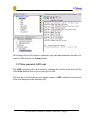
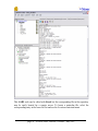
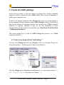
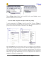
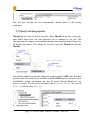
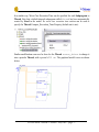
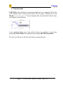
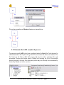
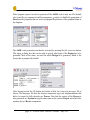
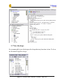
1
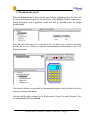
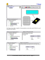
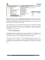
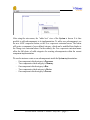
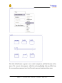
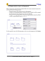
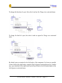
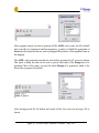
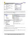
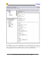
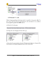
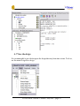
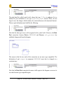
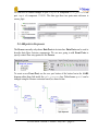
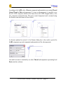
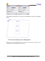
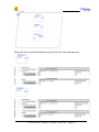
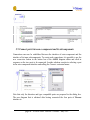
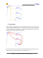
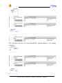
Stood 5.2
AADL
Tutorial
STOOD AADL Tutorial © Ellidiss - May 2007 - page 1
Pierre Dissaux
Ellidiss Technologies
page 2 - STOOD AADL Tutorial © Ellidiss - May 2007
Contents
1Introduction.................................................................................................................................................... 5
2Define a workspace........................................................................................................................................ 6
2.1Stood shortcut..........................................................................................................................................6
2.2Stood initialization file............................................................................................................................ 7
2.3Requirements file.................................................................................................................................... 8
2.4Launching Stood......................................................................................................................................8
2.5Create a Stood project........................................................................................................................... 10
3Create an AADL system...............................................................................................................................11
3.1Create a new design of kind “aadl system”...........................................................................................11
3.2Lock the system to enter edit mode.......................................................................................................11
3.3Document the project............................................................................................................................ 13
3.4Document the system............................................................................................................................ 14
3.5Create subcomponents...........................................................................................................................16
3.6Rename and give a type to subcomponents...........................................................................................19
3.7Create bus access connections...............................................................................................................20
3.8Create ports............................................................................................................................................21
3.9Rename and customize ports.................................................................................................................22
3.10 Create port connections...................................................................................................................... 24
3.11 Generate the AADL code for the system........................................................................................... 25
3.12 Show generated AADL code..............................................................................................................27
3.13 Create a design report.........................................................................................................................29
3.14 Save the design...................................................................................................................................34
4Create an AADL package.............................................................................................................................35
4.1Create a new design of kind “aadl package”.........................................................................................35
4.2Lock the package to enter edit mode.....................................................................................................36
4.3Create Data component classifiers inside the package..........................................................................37
4.4Rename the Data component.................................................................................................................38
4.5Specify component type and implementation....................................................................................... 39
4.6Define subcomponents of a Data component........................................................................................40
4.7Define Data component extension........................................................................................................ 41
4.8Define the public section of the package...............................................................................................42
4.9Define Data Subprograms..................................................................................................................... 43
4.10 Specify Subprogram Parameters........................................................................................................ 44
4.11 Add AADL Properties........................................................................................................................46
4.12 Add textual comments........................................................................................................................47
4.13 Show full AADL diagram of the package..........................................................................................48
4.14 Generate the AADL code for the package......................................................................................... 49
4.15 Show generated AADL code..............................................................................................................50
STOOD AADL Tutorial © Ellidiss - May 2007 - page 3
4.16 Generate C++ code.............................................................................................................................52
4.17 Save the design...................................................................................................................................53
5Create an AADL process..............................................................................................................................54
5.1 Create a new design by export............................................................................................................ 54
5.2Import a list of design requirements......................................................................................................55
5.3Clean up the environment......................................................................................................................56
5.4Import a package................................................................................................................................... 58
5.5Change data ports type.......................................................................................................................... 59
5.6Add ports to the process........................................................................................................................ 61
5.7Add subcomponents to the process....................................................................................................... 62
5.8Create and customize ports in subcomponents......................................................................................64
5.9Connect ports between a component and its subcomponents............................................................... 66
5.10 Connect ports between subcomponents............................................................................................. 67
5.11 Specify flows......................................................................................................................................68
5.12 Specify real-time properties............................................................................................................... 70
5.13 Specify modes.................................................................................................................................... 72
5.14 Generate the AADL code for the process.......................................................................................... 75
5.15 Show generated AADL code..............................................................................................................77
5.16 Generate Ada code............................................................................................................................. 79
5.17 Save the design...................................................................................................................................80
6Conclusion....................................................................................................................................................81
page 4 - STOOD AADL Tutorial © Ellidiss - May 2007
1 Introduction
The purpose of this document is to describe the standard modelling process to be used to
build a new AADL project with Stood. It is not a complete tutorial or user manual for
Stood and knowledge about the AADL is a prerequisite for using this document. Please
refer to the official AADL web site (www.aadl.info) to learn more about this
standard.
In addition to the various modelling concepts defined by the AADL standard, we need to
introduce the following additional ones that are more development process oriented:
A Stood Design is the main modelling entry point. It represents the root of a hierarchy of
components or packages. A Design may be used to define the overall system, a particular
set of concrete components describing an executable software application, or a library of
abstract components. In the first case, the Design is directly associated to an AADL
system instance. In the second one, it will represent an AADL process instance, whereas
in the last case, it will represent an AADL package. A fourth case, still subject to deeper
investigations, concerns the software to hardware binding activity, for which the current
entry point is an AADL processor.
A Stood Project refers to a set of Designs that collaborate in a common realization. The
Project specifies the scope of the realization, and restricts the access to other nonreferenced Designs.
A Stood Session begins when a user launches the tool and ends when Stood is closed.
Stood is a multi-user environment, so that several Sessions may be opened on a same
Project, or even on a same Design.
A Stood Workspace is a user-defined disk area where Projects and Designs can be
stored.
This tutorial includes the following sections:
1. Define a Workspace, launch Stood and create a Project
2. Create a Design representing an AADL system
3. Create a Design representing an AADL package
4. Create a Design representing an AADL process
STOOD AADL Tutorial © Ellidiss - May 2007 - page 5
2 Define a workspace
It is possible to launch Stood from the start-up menu or from the desktop icon that are
created by the Windows installer program. However in that case, any customization of
the tool requires altering the original distribution, which may be an issue if several users
or several Projects require different customizations.
This is the reason why it is often recommended to launch Stood from a Workspace that
can be dedicated to each user or Project. Such a Workspace consists in a simple
directory that must contain at least two elements:
- a shortcut to the Stood executable file (under Windows) or a redirecting shell
script (under Unix)
- a local initialization file (stood.ini under Windows or .stoodrc under
Unix)
In addition, this Workspace may contain other Project related data such as lists of
textual requirements or subdirectories with legacy source code to be reused in the
Project.
2.1 Stood shortcut
Stood shortcut must be created by one of the standard Windows procedures. However, it
is necessary to customize it so that the Workspace can be used as the default storage
area for the new created Projects when Stood is actually launched from there.
Open the properties box of the shortcut, select the shortcut tab, and modify the target
field so that it points to the current Workspace directory instead of the installation one.
page 6 - STOOD AADL Tutorial © Ellidiss - May 2007
2.2 Stood initialization file
The second customization that may be required consists in modifying one or several of
the properties that are specified in the Stood initialization file (stood.ini under
Windows or .stoodrc under Unix). A complete specification of these properties is
provided in the Stood Administrator Manual.
Only the properties that differ from the default initialization file located in the installation
directory must be specified locally. All the other properties will be automatically
inherited. Typical properties that may be customized locally are the various environment
variables that are used by Stood to interact with external tools, such as compilers or
verification tools.
[Environment]
ADA_PATH=C:\cygwin\bin
C_PATH=C:\cygwin\bin
CPP_PATH=C:\cygwin\bin
REQTIFY_PATH=C:\reqtify\bin.w32
OSATE_PATH=/cygdrive/C/topcased/eclipse/eclipse.exe
CHEDDAR_PATH=/cygdrive/C/CHEDDAR-2.0/cheddar.exe
STOOD AADL Tutorial © Ellidiss - May 2007 - page 7
2.3 Requirements file
The Workspace directory may also contain one or several Project specific textual
requirements files that may be imported into Stood. Once imported, it will be possible to
specify requirements coverage for each modelling entity.
The internal format for Stood compliant requirements files is quite simple as it consists
in plain ASCII text declaring one requirement per line. Each requirement is expressed by
a unique identifier and a free comment, separated by a tab character.
CALC101
CALC102
CALC111
CALC112
CALC121
CALC122
CALC123
CALC124
CALC131
CALC132
CALC133
interact with the Keyboard
interact with the Screen
define integer type
define real type
add integers
add reals
sub integers
sub reals
scan the Keyboard
perform the operation
display on Screen
Such a requirements file may be easily generated by a requirements management tool
such as Doors™. Note that thanks to a specific connection feature, it is also possible to
directly import requirements and export coverage information from and to a traceability
graph defined in the Reqtify™ tool.
2.4 Launching Stood
If not launched from the Workspace shortcut, it is also possible to launch Stood either
from the desktop shortcut or from the standard Windows start up menu.
Note that these two options will not be available if the corresponding set up has been
deactivated during the installation process.
page 8 - STOOD AADL Tutorial © Ellidiss - May 2007
When launched, Stood shows a start up screen during its initialization phase, and then
opens its main windows, which looks as the picture below:
STOOD AADL Tutorial © Ellidiss - May 2007 - page 9
2.5 Create a Stood project
First step of the modelling process consists in either opening an existing Project or
creating a new one. Projects can be managed from the File menu.
For the purpose of this tutorial, we create a new Project and specify its name in the
dialog box.
We can now import existing Designs within the scope of our Project thanks to the
File/Add to project menu, create new Designs from existing source code thanks to the
Design/New design from… menus or create new local Designs with the Design/New
design menu.
This last choice offer several options. The new created Design may be profiled as a
HOOD Design, in which case one of the options design, generic or virtual node must be
chosen, or as an AADL Design, in which case one of the options aadl package, aadl
system, aadl process or aadl processor must be selected.
This tutorial explains how to create in a context of a consistent Project:
- AADL Systems to define concrete system wide architectures composed of
hardware and software components.
- AADL Packages to specify libraries of abstract components, and especially
abstract Data components to be used as classifiers for ports and parameters.
- AADL Processes to perform complete software design activities including
architectural design, detailed design and coding, model analysis, source code and
design documentation generation.
These three modelling processes are described in the next three sections. The last section
explains how to quit Stood.
page 10 - STOOD AADL Tutorial © Ellidiss - May 2007
3 Create an AADL system
Specifying a System with Stood consists in effect in building a System Instance. Instead
of creating abstract component types, component implementations and then instantiating
them as subcomponents, the designer can directly define subcomponents in a hierarchical
way, and then specify whether they correspond to instances of already defined abstract
components or of anonymous abstract components that will have to be automatically
created while producing the textual AADL specification.
3.1 Create a new design of kind “aadl system”
To create a new System inside the current Project (cf.§2.5), use the menu Design/New
design/aadl system… and then specify its name in the dialog box.
Note that a Design name in Stood must be alphanumeric (i.e. only contain characters ‘a’
to ‘z’, ‘A’ to ‘Z’, ‘0’ to ‘9’ or the underscore character ‘_’).
3.2 Lock the system to enter edit mode
When it has just been created, the new System design is automatically loaded and it is
shown in the AADL graphical editor as an empty box at the middle of a larger one
representing the Project.
STOOD AADL Tutorial © Ellidiss - May 2007 - page 11
However, this System design is set to read-only mode by default. To enable performing
modifications on this System, it is necessary to “lock” it so that no other user will be
allowed to get a concurrent write access to the model.
When a System design is locked (may be modified in the current Session), a green
padlock is shown at the left of its name.
page 12 - STOOD AADL Tutorial © Ellidiss - May 2007
3.3 Document the project
When the System design is selected in the upper left list of Stood window, the lower left
list shows description sections for the local view of the Project. Default sections are a
textual descriptions and a graphical sketch that will be included inside the design
documentation.
Note that each time some text is entered in the text input area, it must be saved by
pressing the Save text button, or using the corresponding contextual menu or the Ctrl-S
keyboard shortcut.
Note that the sketches are provided for documentation purpose only and that they do not
carry any semantic information.
Note also that the other sections List of Requirements, Design Tree and Inheritance Tree
are automatically filled in by Stood.
STOOD AADL Tutorial © Ellidiss - May 2007 - page 13
3.4 Document the system
When the System design tree is deployed in the upper left list, it shows another line with
the same name. This corresponds to the System component instance to be edited.
Note that when a component is selected in the upper left list, current selection of the
graphical editor and contents of the lower left list are automatically updated. It is thus
possible to fill in the textual sections and sketches that are available to describe each
component individually.
The Statement of the Problem section (see the figure above) must be used to provide
textual details about how the currently selected component contributes in solving a
particular modelling problem.
The Sketch of the Problem section (see figure below) can be used to complete this
information by an informal drawing that will be included into the design documentation.
page 14 - STOOD AADL Tutorial © Ellidiss - May 2007
Next figures show other examples of documentation sections that can be filled in for each
component individually.
STOOD AADL Tutorial © Ellidiss - May 2007 - page 15
Stood promotes the concept of “incremental documentation” that consists in asking the
designer to document each modelling element independently at the time he or she is
performing the modelling actions. The final design documentation will compile all these
elementary sections to build a complete report.
This modelling process also recommends documenting each component before going
deeper in the architecture hierarchy. For instance, the Identification of Subcomponents
documentation section can be used as a guideline for actually creating the
subcomponents (see next chapter).
3.5 Create subcomponents
In the graphical editor, a component can be represented either by its “black box” view
that shows the contents of the corresponding component type, or by its “white box” view
that shows the contents of the corresponding component implementation.
In the picture below, the “black box” view of the System component is shown. To show
its “white box” view, it is necessary to go one step down the hierarchy. This action can
be performed by double-clicking inside the component box or using the enter contextual
menu.
page 16 - STOOD AADL Tutorial © Ellidiss - May 2007
After using the enter menu, the “white box” view of the System is shown. It is thus
possible to add subcomponents to its implementation. To add a new subcomponent, use
the new AADL component button, or the New component contextual menu. The button
will create a component of a pre-defined category, which can be modified later thanks to
the Change into contextual menu. On the contrary, the New component contextual menu
offers the full choice of valid categories for creating subcomponents within the current
component implementation.
We can for instance create seven subcomponents inside the System implementation:
- One component which category is Processor
- Two components which category is Memory
- One component which category is Bus
- Two components which category is Device
- One component which category is Process
STOOD AADL Tutorial © Ellidiss - May 2007 - page 17
Note that a default name is given to new created components, and that this name is the
name of the concrete subcomponent within the enclosing System, that may differ from
the corresponding component type classifier and component implementation names.
page 18 - STOOD AADL Tutorial © Ellidiss - May 2007
3.6 Rename and give a type to subcomponents
When a component is selected in the graphical editor, the rename contextual menu can be
used to perform the following actions:
- Change the name of the selected concrete subcomponent.
- Change the corresponding abstract component type (by default, it will be assumed
that subcomponent and component type name are identical)
- Change the corresponding abstract component implementation name (by default,
it will be assumed that this name is others)
It is thus possible to give the following names to the seven subcomponents of the System
STOOD AADL Tutorial © Ellidiss - May 2007 - page 19
3.7 Create bus access connections
To create bus access connections, use the new connection button of the graphical editor.
Then click on the accessed bus component before clicking on the accessing component.
This results in a graphical bus access connection between the Bus and the Memory
components.
Additional connections may now be added inside our System implementation.
page 20 - STOOD AADL Tutorial © Ellidiss - May 2007
3.8 Create ports
To express for instance that the Process can exchange data with the Device components
it is necessary to add ports. To create a port in a component type, use the new port button
of the graphical editor. Click on the button (a), drag the mouse on the target component
(b) and then click to create the port (c).
(a)
(b)
STOOD AADL Tutorial © Ellidiss - May 2007 - page 21
(c)
We can thus create four ports as shown in the figure below:
Note that these ports have been created with a default name and as In Event Ports by
default. Next section explains how to modify the name, the direction and the kind of the
ports.
3.9 Rename and customize ports
To rename a port, first select it and then use the Rename contextual menu.
page 22 - STOOD AADL Tutorial © Ellidiss - May 2007
To change the direction of a port, first select it and use the Change into contextual menu.
To change the kind of a port, first select it and use again the Change into contextual
menu.
By default, ports are attached to the left border of the component. It is however possible
to move them to the right border, using the Right alignment contextual menu. In a similar
way, a port attached to the right border can be moved back to the left border thanks to the
Left alignment contextual menu.
STOOD AADL Tutorial © Ellidiss - May 2007 - page 23
We can now customize the four ports as follow:
3.10 Create port connections
To create connections between ports, use the new connection button of the graphical
editor. First click on the button (a), then click on one of the connected ports (b) and then
on the other port (c).
Note that port compatibility is verified before accepting to create the connection. These
verifications concern, port kind, port direction and port type for Data Ports and Event
Data Ports.
page 24 - STOOD AADL Tutorial © Ellidiss - May 2007
(a)
(b)
(c)
We can thus create port connections between the Process and each of the two Devices.
3.11 Generate the AADL code for the system
Our model has been created with just a few mouse clicks in the graphical editor. It is
however possible to generate a full AADL specification from it.
To generate textual AADL code from a graphical model in Stood, the Code tab must be
selected instead of the Graphic Design one.
The new button bar shows two buttons. The first button on the left is called add pragma
and may be used to customize the code generation. Pressing this button opens a dialog
box showing the list of the possible options that can be selected.
STOOD AADL Tutorial © Ellidiss - May 2007 - page 25
Select pragma compact in order to generate all the AADL code in only one file (default
rule is one file per component) and then pragma no_graphics to disable the generation of
Stood specific properties that are used to propagate the positions of the graphical items in
the diagram.
The AADL code generation can then be activated by pressing the full extraction button.
This opens a dialog box that can be used to specify which part of the Design has to be
generated. Most of the times, we need the whole Design to be generated, which is the
choice that is proposed by default.
After having pressed the Ok button and waited a little, the extraction messages file is
shown.
page 26 - STOOD AADL Tutorial © Ellidiss - May 2007
The messages file lists the abstract component types and implementations that had to be
created to fully describe our System instance.
3.12 Show generated AADL code
The AADL generated code can be shown by changing the selection in the lower left list
of the Stood window from extraction messages to aadl.
Note that, due to the fact that we put a pragma compact, AADL code has been associated
to the root component in the hierarchy only.
STOOD AADL Tutorial © Ellidiss - May 2007 - page 27
This AADL code can be edited with Stood, but the corresponding file in the repository
may be easily located for a remote access. To locate a particular file, select the
corresponding entry in the lower left list and use the Location contextual menu.
page 28 - STOOD AADL Tutorial © Ellidiss - May 2007
3.13 Create a design report
Stood also offers a seamless way to create design documentation reports. Such a report
compiles all the appropriate information that has been entered while building the model.
This includes textual and graphical entries. To switch on the report settings tool, select
the documentation tab.
STOOD AADL Tutorial © Ellidiss - May 2007 - page 29
First step consists in defining the components that must be included in the report. To
select all the components, use the select all button.
The effect of this action is to display a small printer icon at the left of the component
name to mean that it has to be included to the report (the small floppy disk icon means
that the component has not been saved yet).
Second step consists in selecting the output format for the report. This can be done by
selecting the appropriate button among html (default), mif, pdf, ps, rtf and tps. Select rtf.
Last step is the activation of the document generation that will start after the print button
has been pressed.
page 30 - STOOD AADL Tutorial © Ellidiss - May 2007
A standard Windows file navigator is then shown to select the output file. A default
filename and directory is proposed.
As soon as the document generator has finished to work, it is possible to view the report
by opening its containing directory. If the default output file location was not changed, it
can be found by using the menu Tools/Open directory/design directory.
STOOD AADL Tutorial © Ellidiss - May 2007 - page 31
The design directory contains all the information related to the Design. Generated
documentation may be found inside the _doc subdirectory.
Note that the AADL code that was generated previously can be found in the _aadl
subdirectory.
page 32 - STOOD AADL Tutorial © Ellidiss - May 2007
The figure next page shows the result of the documentation generation with the RTF
format.
STOOD AADL Tutorial © Ellidiss - May 2007 - page 33
3.14 Save the design
It is recommended to save the design to the design directory from time to time. To do so,
use the menu Design/Save design.
Note that the save icons that are shown at the right of the component names will
disappear once they are saved.
page 34 - STOOD AADL Tutorial © Ellidiss - May 2007
4 Create an AADL package
In the previous section, we did not explain (in purpose) how existing component
classifiers could be referenced in other AADL models. This is however mandatory to
enable proper component reuse.
In order to be properly referenced with a Project wide scope, it is a good practice to
group component classifier definitions within AADL Packages. In theory, this should be
done for any category of component, however the particular case of Data component
classifiers is especially important as they are not only instantiated to create
subcomponents, but also to specify the actual data type of Data Ports, Event Data Ports
or Subprogram Parameters.
This section explains how to create an AADL Package that provides a set of Data
component classifiers.
4.1 Create a new design of kind “aadl package”
To create a new Package inside the current Project (cf.§2.5), use the menu Design/New
design/aadl package… and then specify its name in the dialog box.
Note that a Design name in Stood must be alphanumeric (i.e. only contain characters ‘a’
to ‘z’, ‘A’ to ‘Z’, ‘0’ to ‘9’ or the underscore character ‘_’).
STOOD AADL Tutorial © Ellidiss - May 2007 - page 35
4.2 Lock the package to enter edit mode
When it has just been created, the new Package design is automatically loaded and it is
shown in the AADL graphical editor as an empty box at the middle of a larger one
representing the Project.
However, this Package design is set to read-only mode by default. To enable performing
modifications on this Package, it is necessary to “lock” it so that no other user will be
allowed to get a concurrent write access to the model.
page 36 - STOOD AADL Tutorial © Ellidiss - May 2007
When a Package design is locked (may be modified in the current Session), a green
padlock is shown at the left of its name.
4.3 Create Data component classifiers inside the package
To create components in the Package, it must be opened first. To open a Package, it
must be selected and the contextual menu enter must be used. An alternate solution is to
perform a mouse double click inside the boundaries of the Package.
When the Package has been opened and is selected, it is possible to create components,
either with the new AADL component button (in which case a Data component classifier
will be created by default), or with the new component contextual menu. After the button
or the menu has been used, a new box is shown on the diagram and a new component is
added to the top left list. Default name given to new components is the name of the
container box followed by an integer value.
STOOD AADL Tutorial © Ellidiss - May 2007 - page 37
4.4 Rename the Data component
To rename the new component, it must be selected first (on the diagram or in the list),
and the contextual menu rename must be used. This opens a dialog box where the actual
name of the component can be given.
Note that within a Package, only component classifiers are described, thus Stood
component name generally matches the AADL component type name. However, in case
of several components of the same type, but of different implementation, the box name
will be used to distinguish them, as explained in next chapter.
page 38 - STOOD AADL Tutorial © Ellidiss - May 2007
4.5 Specify component type and implementation
Within a Package, a unique Stood component is used to represent both AADL
component type and implementation. If two components have the same type and different
implementations, two Stood components must be created. The three fields of the rename
dialog box can then be used to specify the unique Stood component name, the AADL
type name and the AADL implementation name.
In the example below, two Stood components keyboard_digit and
screen_digit have been created. They have the same AADL type name digit and
different implementation name keyboard and screen.
STOOD AADL Tutorial © Ellidiss - May 2007 - page 39
4.6 Define subcomponents of a Data component
According to the AADL standard, a Data component classifier can accept
subcomponents that must also be instances of Data components. As a special case,
subcomponents of Data component classifiers are managed by Stood as a list of typed
Attributes. This is in fact compliant with the way software structured data types (Ada
record, C struct, C++ class) are handled by the tool.
When a Data component classifier is selected on the diagram or in the top-left list, a
dedicated SUBCOMPONENTS section is available inside the component descriptor in the
bottom-left list. This section contains a formal declaration of the list of the Data
subcomponent names associated with their corresponding classifier reference (name of a
Data component classifier). Note that keyword ATTRIBUTES must not be removed and
that the list separator is a comma.
To illustrate this, we can create a new Data component classifier called real and
specify that it has two subcomponents int_part and dec_part that are both
instances of integer.
Note: do not forget to use the save test button after any change in the text input area.
page 40 - STOOD AADL Tutorial © Ellidiss - May 2007
4.7 Define Data component extension
According to the AADL standard, a Data component classifier may be specified as an
extension of another Data component classifier. Such an extension mechanism can be
compared to software class inheritance in object-oriented languages. The fact that a Data
component classifier extends another Data component classifier can be expressed on the
diagram thanks to a graphical connection. To create such a connection, for instance to
specify that integers and floats are kind of numbers, please operate as follow:
(a) create a new Data component classifier called number
(b) click on the new connection button of the AADL graphical editor
(c) then, select the descendent Data component classifier
(d) and finally select the ancestor Data component classifier.
STOOD AADL Tutorial © Ellidiss - May 2007 - page 41
Note: the graphical representation of the extend connection does not comply with the
recommendation of the annex A of the standard.
This component extension information can also be edited textually. It can be accessed by
selecting the EXTENDS section of the component descriptor while the component is
selected on the diagram or in the top-left list.
4.8 Define the public section of the package
When adding Data component classifiers in a Package with Stood, they are put in its
private section by default. To let a Data component classifier become public, it must be
selected and the contextual menu Set public must be used.
page 42 - STOOD AADL Tutorial © Ellidiss - May 2007
In order to be able to distinguish between public and private Data component classifiers,
the former are listed in the left border of the Package box in the diagram. Note that this
graphical notation is specific to Stood. For the purpose of our example, we can for
instance specify that Data component classifiers integer, float,
keyboard_digit and screen_digit are public, whereas number remains
private.
4.9 Define Data Subprograms
Like with other object oriented languages, it is possible to define the methods or member
functions that are associated to a Data component classifier. In AADL they are called
data Subprogram features.
To create Subprograms, click on the new subprogram button of the AADL graphical
editor, then select a Data component classifier.
STOOD AADL Tutorial © Ellidiss - May 2007 - page 43
The new Subprogram is given a default name. The rename contextual menu can be used
to change it.
4.10 Specify Subprogram Parameters
Whereas Ports can carry a single event or data message, Subprograms can express more
complex dataflows that are defined by a list of directional typed Parameters. In Stood,
this parameters list must be entered in the port or subpg declaration section as shown in
the sequence of screenshots below.
The syntax that is used by Stood to specify a list of Parameters for a Subprogram is the
one recommended by HOOD which is very similar to what is defined by the Ada
standard. The syntax for a single Parameter is (list separator is a semicolon):
<parameter_name> : <direction> <parameter_type>
page 44 - STOOD AADL Tutorial © Ellidiss - May 2007
(a) Select the Subprogram in the diagram or in the list. The default list of Parameters is
shown in the text input area. In case of a data Subprogram defined in a Data component
classifier, default Parameter is the receiver which default name is me and default type is
the Data component classifier.
(b) Modify the Parameters in the text input area. Do not forget to save the changes with
the button, contextual menu or keyboard shortcut.
(c) Note that specified Parameter type is checked against Stood cross reference table
and the result of this analysis is shown in the right hand side of the text input area.
By specifying proper Parameters, we can express that the two data Subprogram
features of Data component classifier number are from_digits with an input
Parameter of type keyboard_digit, and to_digits with an output Parameter of
type screen_digit.
STOOD AADL Tutorial © Ellidiss - May 2007 - page 45
4.11 Add AADL Properties
AADL entities specification can be refined by a set of predefined or project-specific
Properties. The way to enter predefined Properties with Stood 5.2 differs from what
was proposed with Stood 5.1. In Stood 5.2, all the predefined Properties have been
included into the default configuration, which simplifies their use. Note that it is possible
to customize this list in the tool configuration files, to hide those Properties that are not
relevant for the current Project.
When a component or a feature is selected, the list of possible valid Properties can be
shown in the INTERFACE section. A contextual help is available for each individual
Property.
page 46 - STOOD AADL Tutorial © Ellidiss - May 2007
To add a Property association, first select the appropriate AADL entity (here,
keyboard_digit Data component classifier), and the chosen Property in the list
(here, Source_Data_Size). Then enter the Property value in the text input area and
save with the button, the contextual menu or the keyboard shortcut.
Note that a default value is proposed for each Property. To display this default value,
use paste from template contextual menu of the text input area.
4.12 Add textual comments
It is recommended to insert comments and other textual information inside the design
data structure while creating new entities. These comments may be used to provide
explanations about the “why”, “what” and “how” of each component or feature. The
standard configuration of the tool proposes a structured list of comment sections that can
however be customized to better fit any other documentation strategy. To fill in one of
the proposed documentation section, first select the appropriate entity and one of the
proposed (text) sections.
STOOD AADL Tutorial © Ellidiss - May 2007 - page 47
Text can be entered inside the text input area and must be saved with the button,
contextual menu or keyboard shortcut.
4.13 Show full AADL diagram of the package
The complete AADL diagram for our Package is now as shown below:
Note that the corresponding graphical representation of the same model in UML and
HOOD is also available, simply by switching the notation selector.
page 48 - STOOD AADL Tutorial © Ellidiss - May 2007
4.14 Generate the AADL code for the package
To generate textual AADL code from a graphical model in Stood, the Code tab must be
selected instead of the Graphic Design one. The new button bar shows two buttons. The
first button on the left is called add pragma and may be used to customize the code
generation. Pressing this button opens a dialog box showing the list of the possible
options that can be selected. Note that some options may have already been automatically
inserted by Stood, as it is the case here.
Select pragma compact in order to generate all the AADL code in only one file (default
rule is one file per component) and then pragma no_graphics to disable the generation of
Stood specific properties that are used to propagate the positions of the graphical items in
the diagram.
The AADL code generation can then be activated by pressing the full extraction button.
This opens a dialog box that can be used to specify which part of the Design has to be
generated. Most of the times, we need the whole Design to be generated, which is the
choice that is proposed by default.
STOOD AADL Tutorial © Ellidiss - May 2007 - page 49
After having pressed the Ok button and waited a little, the extraction messages file is
shown. The messages file lists the abstract component types and implementations that
had to be created to fully describe our Package.
4.15 Show generated AADL code
The AADL generated code can be shown by changing the selection in the lower left list
of the Stood window from extraction messages to aadl.
Note that, due to the fact that we put a pragma compact, AADL code has been associated
to the root component in the hierarchy only.
page 50 - STOOD AADL Tutorial © Ellidiss - May 2007
This AADL code can be edited with Stood, but the corresponding file in the repository
may be easily located for a remote access. To locate a particular file, select the
corresponding entry in the lower left list and use the Location contextual menu.
STOOD AADL Tutorial © Ellidiss - May 2007 - page 51
4.16 Generate C++ code
Without changing anything in the design model, it is possible to also generate Ada, C or
C++ source code. The process for generating C++ code (for instance) is very similar to
the one applied to generate the AADL code, i.e.:
(a) Select the Code tab again:
(b) Change the source language tab from aadl to cpp:
(c) Press the full extraction button, then the OK button in the dialog box. Generated files
can be shown by selecting the appropriate items in the selection lists:
page 52 - STOOD AADL Tutorial © Ellidiss - May 2007
4.17 Save the design
It is recommended to save the design to the design directory from time to time. To do so,
use the menu Design/Save design.
STOOD AADL Tutorial © Ellidiss - May 2007 - page 53
5 Create an AADL process
The third kind of Design that can be managed with Stood is associated to an AADL
Process. Such a Design represents a software program for which it is possible to generate
a complete set of target language source files that can be compiled and linked to produce
an executable file. It is possible to create a Design of kind AADL Process thanks to the
Design/New design menu. Another option consists in creating a new Design by exporting
a Process subcomponent defined in an AADL System.
5.1 Create a new design by export
In the Design calc_system, we defined a Process subcomponent called
calc_process. It would be possible to refine the contents of this Process within this
Design. However, it may be interesting to isolate the pure software part of the System in
a separate Design to complete software design and coding activities until the end.
To do so, after having loaded the calc_system Design again, calc_process
component must be selected and the export contextual menu must be used, as shown
below:
A new Design is added to the list of the Project AADL_calculator. This new Design
now needs to be selected (loaded) and locked (opened in read-write mode) as shown
below.
page 54 - STOOD AADL Tutorial © Ellidiss - May 2007
5.2 Import a list of design requirements
It is possible to import the list of software requirements that must be covered by the
current design and coding activities. The simplest way to import such a list of
requirements consists in reading a tabulated ASCII text file that can be easily produced
by any requirements management tool. Such a file must be formatted as follow to be
properly imported by Stood:
- one requirement per line
- two fields separated by a tab character per requirement: the unique requirement
ID and a comment.
As soon as such a file is available, first switch Stood lifecycle tab to Requirements:
Then click on the button load requirements from text:
A file navigator dialog is shown in which the appropriate file must be selected. Our
Workspace contains a file called Requirements.txt which contents was described
in chapter 2.3.
STOOD AADL Tutorial © Ellidiss - May 2007 - page 55
Once the file is loaded, the corresponding list of requirements appears in Stood. Note
that a small red gauge is shown at the left of each individual item, which means that the
requirement is not covered yet by any design entity.
5.3 Clean up the environment
Current Design has been created by exporting a Process subcomponent of an AADL
System in another Design. This export function also propagates information about the
environment of the exported component, and in particular, all the sibling subcomponents.
However, they are not all relevant anymore in the context of our new Design.
page 56 - STOOD AADL Tutorial © Ellidiss - May 2007
To clean up this environment, switch the lifecycle tab to Graphic Design to show the
AADL diagram, select individually each component to be removed and use the Delete
contextual menu as shown below:
After having deleted all the components that are note directly in interaction with
calc_process, the cleaned model now looks like the following:
STOOD AADL Tutorial © Ellidiss - May 2007 - page 57
5.4 Import a package
In the model we have imported from calc_system, we did not specify precisely the
data types associated to the Data Ports. We now want to reference the Data component
classifiers we defined in the numbers Package to give a type to the Data Ports. The
most consistent way to do that in Stood requires the Package to be imported first within
the Design scope.
In the AADL diagram, the outer box being selected (aadl_calculator), use the
New package contextual menu to create a local representation of a remote Package:
A new box has been added to the diagram, with the default name Extern. To change
this name, use the Rename contextual menu (the Extern Package must be selected).
Let us now give to this local Package the name of the actual Package we created in the
Project, i.e. numbers.
page 58 - STOOD AADL Tutorial © Ellidiss - May 2007
Stood has now made the association between our local Package and the actual remote
Design of the same name. This will allow us to use the various Data component
classifiers defined in the Package numbers in the current Design. To check the available
Data component classifiers, double-click on the local Package numbers:
Note that if changes are made to the remote Package, they will be propagated to the local
copy only during a Design load.
5.5 Change data ports type
When we added Data Ports to subcomponents in section 3.8, we did not care about the
associated data type. A default data type T_Flow was used. It is now possible to
reference the Data component classifiers provided by the imported Package to specify
the actual type of the Data Ports. To illustrate how a port definition can be modified,
select section port or subpg declaration section for port input in component
calc_process.
STOOD AADL Tutorial © Ellidiss - May 2007 - page 59
The right hand list, called symbol table, shows that type T_Flow is unknown. Let us
modify the port declaration to use type keyboard_digit instead. Please, do not
forget to save the changes with the button, the contextual menu or the keyboard shortcut.
The new port declaration must look like the following:
Note that the data type is now well recognized in the symbol table. However, the Data
Port connection between Device KEYBOARD and Process calc_process has
suddently disappeared from the diagram.
The reason is that the two ends of the connection are no more type compatible. The
declaration of port output in component KEYBOARD must also be changed in a
consistent way:
Note that the Data Port connection becomes visible again in the diagram as soon as its
two ends become type compatible again.
page 60 - STOOD AADL Tutorial © Ellidiss - May 2007
We can now do similar changes to port output of component calc_process and
port input of component SCREEN. The data type these two ports must reference is
screen_digit.
5.6 Add ports to the process
The Process currently only shows Data Ports in its interface. Data Ports can be used to
describe data flows between components. We are now going to add Event Ports to
specify control flow entry points for the Process.
To create a new Event Port, use the new port button of the button bar in the AADL
diagram editor then click inside the calc_process box. Default name port0 can be
changed using the Rename contextual menu, as shown below:
STOOD AADL Tutorial © Ellidiss - May 2007 - page 61
After having done the same for a second Event Port called off, the diagram must now
be as follow:
5.7 Add subcomponents to the process
It is now time to provide some details about the internals of our Process. The current
graphical representation of calc_process only shows its interfaces. It is its black box
view. In order to be able to edit its internal details, we must enter the component first to
show its white box view. The Enter contextual menu, or a double-click, must be used for
that purpose:
page 62 - STOOD AADL Tutorial © Ellidiss - May 2007
According to the AADL rules, a Process component implementation can contain Thread
Group, Thread or Data subcomponents. To create a subcomponent, it is possible to use
the new AADL component button of the button bar in the AADL diagram editor, or the
New component contextual menu. The newly created component can be renamed using
the Rename contextual menu as shown below:
As already explained in section 3.6, the Rename dialog box is also used to specify the
AADL component type and component implementation of the subcomponents.
Our model can now be enriched by two other Thread subcomponents representing local
Device interface software.
STOOD AADL Tutorial © Ellidiss - May 2007 - page 63
The graphical representation of the internals of our Process now looks like the diagram
below:
5.8 Create and customize ports in subcomponents
Following a top-down modelling process, we must now specify the interface of each
subcomponent. Let us add ports as shown below:
page 64 - STOOD AADL Tutorial © Ellidiss - May 2007
The details for new port declarations are given below for each subcomponent:
STOOD AADL Tutorial © Ellidiss - May 2007 - page 65
5.9 Connect ports between a component and its subcomponents
Connections can now be established between the interface of outer component and the
interface of its inner subcomponents. To create such connections, it is possible to use the
new connection button in the button bar of the AADL diagram editor and click in
sequence on the two ports to be connected. Another solution consists in selecting a port
in the outer component interface and calling the Connect contextual menu.
Note that only the direction and type compatible ports are proposed in the dialog box.
The new diagram that is obtained after having connected the four ports of Process
interface is:
page 66 - STOOD AADL Tutorial © Ellidiss - May 2007
5.10 Connect ports between subcomponents
To connect ports between subcomponents of a same component, it is possible to use the
new connection button in the button bar of the AADL diagram editor and click in
sequence on the two ports to be connected. Another solution consists in selecting a port
in one of the subcomponent interface and calling the Connect contextual menu.
Note that only the direction and type compatible ports are proposed in the dialog box.
The new diagram that is obtained after having connected all the remaining is as follow:
STOOD AADL Tutorial © Ellidiss - May 2007 - page 67
5.11 Specify flows
AADL connections represent point to point interaction between two ports of the same
type and having compatible directions. Event if they do not refer to the same data type,
several connections may participate to a same more global data flow. Stood has a
particular way to express such flow specifications.
For each port involved in a given flow, the flow name must be inserted into the port or
subpg declaration section in replacement to the default name Flow.
page 68 - STOOD AADL Tutorial © Ellidiss - May 2007
Note that port raw_data has been automatically updated thanks to the existing
connection.
STOOD AADL Tutorial © Ellidiss - May 2007 - page 69
Note that port raw_data has been automatically updated thanks to the existing
connection.
5.12 Specify real-time properties
Threads that have been created are aperiodic. When Threads are periodic or sporadic,
more details about their real time behaviour can be managed by the tool. This
subcomponent sub-category can be modified thanks to the contextual menu Change into.
To illustrate this feature, let us change the two driver aperiodic Threads into periodic
Threads:
Note that the graphical notation has changed to comply with the AADL rules. Real time
properties may be entered into the model as standard AADL Properties. However, basic
schedulability analysis information may also be entered through Stood real time
properties section. We can specify for instance that keyboard_driver has a period
of 100 ms and a deadline of 50 ms:
page 70 - STOOD AADL Tutorial © Ellidiss - May 2007
In a similar way, Worst Case Execution Time can be specified for each Subprogram or
Thread. Note that a default internal subprogram called thread has been automatically
created by Stood in the model. Its worst case execution time section can be used to
specify the Thread Compute_Execution_Time Property (default unit is ms):
Similar modifications can now be done for the Thread screen_driver to change it
into a periodic Thread, with a period of 10 ms. The graphical model is now as shown
below:
STOOD AADL Tutorial © Ellidiss - May 2007 - page 71
5.13 Specify modes
AADL Modes can be defined to represent operational states of a component. That is why
a state diagram editor is used to specify them. We are going to illustrate this on the
Thread processing_unit. The state diagram editor can be launched from the Open
state diagram contextual menu:
A new graphical editing area is then selected, where it is possible to create states
representing AADL Modes and transitions representing AADL Mode Transitions.
To create a new Mode, use the New state button or contextual menu:
page 72 - STOOD AADL Tutorial © Ellidiss - May 2007
States are given a default name that can be modified thanks to the Rename contextual
menu. Let us create two Modes: idle and running:
STOOD AADL Tutorial © Ellidiss - May 2007 - page 73
Transitions can be created with the new transition button or contextual menu. First click
on the origin Mode and then on the destination Mode:
Transitions are also given a default name that can be changed with the Rename
contextual menu:
Transitions must also be attached to a triggering Event. Selection of the Event can be
done thanks to the select transition event button or the Transition event contextual menu.
This action opens a dialog box showing all the Ports and Subprograms defined in the
interface of the current component. Note that only In and In Out Event Ports can be
used to trigger Mode Transitions.
page 74 - STOOD AADL Tutorial © Ellidiss - May 2007
We can then complete our Modes definitions as shown below:
5.14 Generate the AADL code for the process
To generate textual AADL code from a graphical model in Stood, the Code tab must be
selected instead of the Graphic Design one. The new button bar shows two buttons. The
first button on the left is called add pragma and may be used to customize the code
generation. Pressing this button opens a dialog box showing the list of the possible
options that can be selected. Note that some options may have already been automatically
inserted by Stood, as it is the case here.
STOOD AADL Tutorial © Ellidiss - May 2007 - page 75
Select pragma compact in order to generate all the AADL code in only one file (default
rule is one file per component) and then pragma no_graphics to disable the generation of
Stood specific properties that are used to propagate the positions of the graphical items in
the diagram.
The AADL code generation can then be activated by pressing the full extraction button.
This opens a dialog box that can be used to specify which part of the Design has to be
generated. Most of the times, we need the whole Design to be generated, which is the
choice that is proposed by default.
After having pressed the Ok button and waited a little, the extraction messages file is
shown. The messages file lists the abstract component types and implementations that
had to be created to fully describe our Process. Note that the context of the Process is
also generated as a System having the same name as the current Project and which also
contains the two Device components.
page 76 - STOOD AADL Tutorial © Ellidiss - May 2007
5.15 Show generated AADL code
The AADL generated code can be shown by changing the selection in the lower left list
of the Stood window from extraction messages to aadl.
Note that, due to the fact that we put a pragma compact, AADL code has been associated
to the root component in the hierarchy only.
This AADL code can be edited with Stood, but the corresponding file in the repository
may be easily located for a remote access. To locate a particular file, select the
corresponding entry in the lower left list and use the Location contextual menu.
The screenshot below shows the result of an AADL code generation that only uses the
information that has been inserted during the previous modelling steps:
STOOD AADL Tutorial © Ellidiss - May 2007 - page 77
Note that this view has new buttons that can be used to activate AADL compliant tools
such as Osate or Cheddar.
page 78 - STOOD AADL Tutorial © Ellidiss - May 2007
5.16 Generate Ada code
Without changing anything in the design model, it is possible to also generate Ada, C or
C++ source code. The process for generating Ada code (for instance) is very similar to
the one applied to generate the AADL code, i.e.:
(a) Select the Code tab again:
(b) Change the source language tab from aadl to cpp:
(c) Press the full extraction button, then the OK button in the dialog box. Generated files
can be shown by selecting the appropriate items in the selection lists (see next page).
Note that the generated Ada source files are stored in a default location in the
Workspace. Location of each file can be found easily thanks to the Location contextual
menu:
STOOD AADL Tutorial © Ellidiss - May 2007 - page 79
5.17 Save the design
It is recommended to save the design to the design directory from time to time. To do so,
use the menu Design/Save design.
page 80 - STOOD AADL Tutorial © Ellidiss - May 2007
6 Conclusion
This tutorial does not provide information about all the possible modelling and model
processing features of Stood. In particular, this first version of the document does not
give explanations about the following important topics that are nevertheless already
supported by Stood 5.2:
-
Create a new Design from a remote AADL textual specification.
Update an existing Design from a remote AADL textual specification.
Create an AADL model from legacy Ada or C source files.
Use the integrated Design verification tools.
Perform software to hardware binding.
STOOD AADL Tutorial © Ellidiss - May 2007 - page 81
page 82 - STOOD AADL Tutorial © Ellidiss - May 2007
STOOD AADL Tutorial © Ellidiss - May 2007 - page 83
www.ellidiss.com
[email protected]
TNI Europe Limited
Triad House
Mountbatten Court
Worall Street
Congleton
Cheshire
CW12 1AG
UK
Ellidiss Technologies
Technopôle Brest-Iroise
115 rue Claude Chappe
29280 Plouzané
Brittany
France
+44 1260 291 449
+33 298 451 870
www.aadl.info