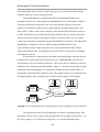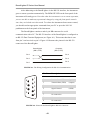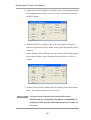
1
BroadLighter-D Bench Series Broadband SLD Light Sources User Manual for Models: BroadLighter D-810-HP, D-840-HP, D-840-HP-I, D-880-HP, D-880-HP-I, D-890-HP BroadLighter D-980-HP BroadLighter D-1300-HP, D-1300-HP-I BroadLighter D-1500-LP Version 1.1 Version date: October 26, 2011 Superlum, Unit 1F, Eastlink Business Park, Carrigtwohill, Co. Cork, Ireland. Phone: +353 21 4533666, Fax: +353 21 4533026, E-mail: [email protected]. www.superlumdiodes.com BroadLighter-D Series User Manual ATTENTION: This page is intentionally left blank. Replace the page with the EC Declaration Conformity when printing and preparing the manual for a customer. Ensure that the EC Declaration has been filled in properly and signed. -2- BroadLighter-D Series User Manual Warranty Warranty Superlum warrants the material and production of the BroadLighter-D Broadband SLD Light Source for a period of 12 months from the date of shipment. During this warranty period Superlum will repair or exchange any units if they are found to be defective in material or workmanship. Repaired products are warranted for the balance of the original warranty period or at least 90 days. For warranty repairs or service the unit must be returned to Superlum. The customer is responsible for all costs incurred to ship the unit back to Superlum. Limitation of Warranty Superlum does not guarantee that this manual is completely free from errors or inaccuracies, and reserves the right to change or correct operating instructions, specifications, or numerical information presented here at any time, without notice. Superlum is not liable for any incidental damage caused by failure of this product. This warranty does not cover: Any defect (or damage to the unit) caused by improper user's operation, such as incorrect connection to the instrument, improper handling of the unit, etc. The accessories coming with the instrument—fiber optical patchcables, AC power cords, etc. The warranty will void if the user opens the unit for disassembling, repairing, or servicing without Superlum's permission. This product is not intended for use in medical and/or life support situations. Statement of Calibration Superlum certifies that this product has been inspected, tested, and calibrated to meet its published specifications. -3- BroadLighter-D Series User Manual Contents Warranty…………………………………………………..…………………... 3 List of Figures………………………………………………………………… 6 List of Tables………………………………………………………………….. 7 General Safety Information………………………………………..….………. 8 Safety Symbols and Terms…………………………………………..………... 10 Acronyms and Abbreviations…………………………………………………. 11 Chapter 1 General Information……………………………………… 12 1.1 In This Manual…….………………………………………………… 1.2 Instrument Description………………………………………………. 13 1.3 Product Specifications………………..……………………………… 21 1.4 Laser Safety Information……………..……………………………… 23 1.4.1 Class 1 Laser Products……..…….………………………… 24 1.4.2 Class 3R Laser Products…..…….……………….………… 27 1.4.3 Class 3B Laser Products…..…….……………….………… 31 Installation………………………………………………… 34 Unpacking and Initial Inspection…………………………...……….. 34 Chapter 2 2.1 12 2.1.1 Unpacking the Instrument………..………………………… 34 2.1.2 Initial Inspection…………………………………………… 34 2.2 Preparation for Use……………………………………..…………… 35 2.3 Fuse Replacement……………..……………………….…….……… 36 Chapter 3 Local Mode of Operation………...………………………. 38 3.1 Front-Panel Features………………………………………………… 38 3.2 Rear-Panel Features…………………………………………………. 40 3.3 Operating Instructions………………………..……………………… 41 3.4 How to Turn Off the Instrument…………………………………….. 43 3.5 Troubleshooting Information………………………………………... 44 -4- BroadLighter-D Series User Manual Chapter 4 Remote Mode of Operation….…………………………… 47 4.1 Introduction to Remote Operation…….…………………….….…… 47 4.2 Description of Data Communication Protocol.….…………..……… 49 4.3 Remote Command Set……………………………….………………. 50 4.4 4.3.1 Identification Query…………….…………..……………… 50 4.3.2 Local/Remote Enable Command………………...………… 51 4.3.3 Local/Remote Check Query……………………….….……. 52 4.3.4 Optical Output Enable Command…………………...…...… 53 4.3.5 Optical Output Check Query………………………….…… 53 The Superlum's BroadLighter Companion Software…..……….….... 54 4.4.1 About the Superlum's BroadLighter Companion Software... 54 4.4.2 Minimum System Requirements…………………………… 55 4.4.3 Getting Started……………………………………………... Chapter 5 56 4.4.3.1 Installing the Software on Your PC System……... 56 4.4.3.2 Connecting the BroadLighter to Your PC System. 56 4.4.3.3 Running the Program……………………………. 57 4.4.3.4 Using the Program…………………………….…. 58 4.4.3.5 Uninstalling the Program………………………... 61 Cleaning Instructions……………………………………... 62 5.1 Safety Precautions…………………………………………………… 62 5.2 Cleaning Procedures……………………………………………….… 63 5.2.1 Cleaning a Non-Lensed Connector…..………….…….…… 63 5.2.2 Cleaning the Front-Panel Optical Adapter…….………….... 65 5.2.3 Cleaning the Instrument Cabinet……………………..……. Chapter 6 65 Service and Support………………………………………. 66 6.1 Returning the Instrument for Servicing……………………………… 66 6.2 Preparing the Instrument for Shipment…………………..…….……. 66 Revision Documentation……………………………………………………… 69 -5- BroadLighter-D Series User Manual List of Figures Figure Page FIGURE A. Illustration of an ESD Wrist Strap……………………………...…..….… 9 FIGURE 1.1. Schematic Illustration of the Principle of Light Combining in the BroadLighter……………………………………………………………….……..….… 14 FIGURE 1.2. Front-Panel Laser Safety Features………………………….……...…… 20 FIGURE 1.3. Rear-Panel Laser Safety Features…………………….…...………….… 20 FIGURE 1.4. Warning Labels for Class 1 Laser Products……………………….……. 25 FIGURE 1.5. Examples of the Output Beam Divergence and the MPE………….…… 26 FIGURE 1.6. Warning Labels for Class 3R Laser Products………………………..…. 28 FIGURE 1.7. Warning Labels for Class 3B Laser Products……………………….….. 31 FIGURE 3.1. Front-Panel Features of the BroadLighter…...……………………….… 38 FIGURE 3.2. Rear-Panel Features of the BroadLighter……………………...………... 40 FIGURE 4.1. The Wiring Configuration for RS-232 Communication……….…....….. 48 FIGURE 4.2. Pinout for the BroadLighter's RS-232 Connector………………….…… 48 FIGURE 4.3. Example of the Program Window……………...……………..………… 57 -6- BroadLighter-D Series User Manual List of Tables Table Page TABLE A. Acronyms and Abbreviations Used……………..……………..…………. 11 TABLE 1.1. BroadLighter Units Description………..……………………….….……. 15 TABLE 1.2. General and Mechanical Specifications…...………………….…….…… 21 TABLE 1.3. List of Contents………………...……………………………..…….…… 22 TABLE 1.4. Classification of the BroadLighters According to IEC 60825-1 (Edition 2.0 2007-03)…………………………..……………………………………………….. 23 TABLE 2.1. AC Line Fuse Specifications……...………………………….…….…… 37 -7- BroadLighter-D Series User Manual General Safety Information The following general safety precautions must be observed during all phases of operation, service, and repair of the instrument. Failure to comply with these precautions or with specific warnings elsewhere in this manual violates safety standards of design, manufacture, and intended use of the instrument. Superlum assumes no liability for the customer’s failure to comply with these requirements. Before Applying Power Verify that the product is set to match the available line voltage, and the correct fuse is installed. Safety Earth Ground This product is a Safety Class I instrument (provided with a protective earth terminal). To minimize shock hazard, the instrument chassis and cabinet must be connected to an electrical ground. The instrument must be connected to the AC power line through a three-conductor power cable, with the third wire firmly connected to an electrical ground (safety ground) at the power outlet. Any interruption of the protective (grounding) conductor or disconnection of the protective earth terminal will cause a potential shock hazard that could result in personal injury. If the instrument is to be energized via an external autotransformer, the ground terminal of the power connector should be connected to the neutral wire of the AC supply. DO not operate the instrument in an explosive atmosphere or in the presence of flammable gases or fumes. DO not use repaired fuses or short-circuited fuse holders. For continued protection against fire, replace the line fuse(s) only with fuse(s) of the same voltage, current rating and type. DO not perform procedures involving cover or shield removal unless you are qualified to do so. Operating personnel must not remove equipment covers or shields. Procedures involving the removal of covers and shields are for use by service-trained personnel only. DO not operate damaged equipment. Whenever it is possible that the safety protection features built into this product have been impaired, either through physical -8- BroadLighter-D Series User Manual damage, excessive moisture or any other reason, remove power and do not use the product. Return the product to Superlum to ensure the safety features are maintained. DO not substitute parts or modify equipment. Because of the danger of introducing additional hazards, do not install substitute parts or perform any unauthorized modification to the product. Return the product to Superlum for service and repair. Electrostatic Discharge (ESD) Precautions There are numerous internal elements inside the instrument which are extremely susceptible to static electricity. Because of this, protection against ESD is essential while you are setting up, cleaning, or inspecting the instrument. Static electricity can build up on your body and can easily damage sensitive internal circuit elements when discharged. Static discharges even too small to be felt can cause permanent damage to the instrument. To prevent it from being damaged by an ESD event, it is necessary to follow the rules below: Always wear an ESD wrist strap (fig. A) connected to the common grounded point, having 1-MOhm resistor in series with it, when handling the ungrounded instrument. Always ground the instrument via either the AC power cord (connected to a properly grounded power outlet) or the rear-panel grounding terminal before starting to work with the instrument. FIGURE A. Illustration of an ESD Wrist Strap. -9- BroadLighter-D Series User Manual Safety Symbols and Terms This section deals with information on the safety symbols and terms which are used on the instrument or in the manual, and gives explanations what they stand for. These symbols and terms indicate precautions you must strictly follow to safely operate the instrument. Before you begin using your BroadLighter, read the following explanations: This symbol indicates the field-wiring terminal that must be connected to earth ground before operating the equipment. It is for protection against electrical shock, in case of a fault. The WARNING sign denotes a hazard. It calls attention to a procedure, practice, or the like, which, if not correctly WARNING performed or adhered to, could result in personal injury. Do not proceed beyond a WARNING sign until the indicated conditions are fully understood and met. The CAUTION sign denotes a hazard. It calls attention to an operating procedure, or the like, which, if not correctly performed or adhered to, could result in damage to or CAUTION destruction of the entire product or part thereof. Do not proceed beyond a CAUTION sign until the indicated conditions are fully understood and met. The NOTE sign denotes important information. It calls attention NOTE to procedures, practice, condition, or the like, which is essential to highlight. The CE mark shows that the product complies with all relevant European Legal Directives. The warning label denotes visible and/or invisible laser radiation. RoHS COMPLIANT 2002/95/EC This label means the compliance with the requirement of the RoHS Directive (Directive 2002/95/EC). -10- BroadLighter-D Series User Manual Acronyms and Abbreviations The necessary information on acronyms and abbreviations is summarized in the following table: TABLE A Acronyms and Abbreviations Used Abbreviation Definition O Degree Celsius mW Milliwatt nm Nanometer dB Decibel V Volt AC Alternating Current AEL Accessible Emission Limit APC Automatic Power Control BLS Broadband Light Source CW Continuous Wave DC Direct Current LED Light Emitting Diode MPE Maximum Permissible Emission NA Numerical Aperture PC Personal Computer SLD Superluminescent Diode SM Single Mode TEC Thermoelectric Cooler C NOTE In case of a term for which the definition is not given here, refer to special reference books for the necessary explanations or consult with Superlum on this issue. -11- BroadLighter-D Series User Manual 1 General Information This chapter contains general information concerning the BroadLighter Broadband SLD Light Source. Included in this chapter are a description of the instrument, a scope of this manual, general specifications, information on the laser Class to which your BroadLighter is assigned, and a description of the laser safety measures employed in this equipment. 1.1 In This Manual This manual contains the most comprehensive information required to install, operate, and clean the Superlum's BroadLighter-D Broadband SLD Light Source. The goal of this section is to give a short overview of the chapters and sections comprising this document. Knowing the layout of the manual helps you find answers to the vast majority of questions you may have about installing, using, programming, cleaning, and servicing your BroadLighter. To this end, the manual has been divided into 6 chapters. Detailed information about the principles of operation, installing, and using the BroadLighter is provided in four chapters which are placed at the beginning of the manual. At the end of the document will be another two chapters containing additional information (i.e. detailed instructions) about cleaning and obtaining service. Use the manual as a reference book when you are installing, operating, or suspecting problems with the instrument. Please read carefully this manual before using your BroadLighter. You should be especially careful to warnings and cautions presented in this manual. (If necessary, refer to section "Safety Symbols and Terms" for definitions of these terms.) If, after reading this manual, some of the explanations given here still remain unclear to you or you need extra information on a particular issue that interests you, do not hesitate to contact Superlum for more details or additional explanations. The chapters in this manual are set out as follows: Chapter 1, "General Information", begins with outlining the scope of this manual, which comes first. After that, you will find background information -12- BroadLighter-D Series User Manual concerning the BroadLighter design—the principles of operation and design as well as the most important changes in this version of the instrument. Following this are technical specifications on the product and laser safety information, which are provided in the corresponding sections of the chapter. Chapter 2, "Installation", takes you through unpacking and inspection procedures and explains how to prepare the BroadLighter for use. At the end of the chapter are instructions on how to replace the AC power line fuse. Chapter 3, "Local Mode of Operation", introduces front- and rear-panel features and provides detailed operating instructions to demonstrate how easy the BroadLighter is to use. Chapter 4, "Remote Mode of Operation", explains how to control the instrument remotely by using a PC. It provides a full description of each command and query supported by the instrument and the most comprehensive information on the Superlum's BroadLighter companion software, which comes with the instrument. Chapter 5, "Cleaning Instructions", deals with a description of the proper cleaning procedures that you should regularly apply to both the BroadLighter and optical accessories, such as optical patchcables, adapters, optical connectors, and the like. Chapter 6, "Service and Support", explains what you should do if you encounter a problem with the instrument. It also gives detailed recommendations for repacking the instrument before sending it for servicing. 1.2 Instrument Description For a number of optical applications, such as optical coherence tomography, optical metrology, characterization of optical components and the like, broadband light sources based on the use of SLD modules are considered to be best suited. The reason for choosing this type of optical modules is related to their remarkable technical parameters: Among all types of modules presented on the market, the SLD modules best combine high optical power similar to that emitted by laser diodes with broadband optical spectra characteristics of LEDs. These advantages of SLDs allow the user to avoid unwanted interference effects, like speckle or ghost signals. In contrast, -13- BroadLighter-D Series User Manual narrowband light sources as laser diodes often give rise to such effects due to high temporal coherence of their output emission. The BroadLighter is a sophisticated SLD-based broadband light source intended for bench use. Among other broadband light sources of this kind, it features excellent performance parameters, easy-to-use front-panel operation, long-term stability of its technical characteristics, high reliability, minimal maintenance, and many others. Today's state-of-the-art design of the BroadLighter allows the source to be used with equal success both in the lab and production areas. It can be controlled either manually by using its front-panel controls or remotely with a PC. For remote control, the instrument is equipped with the standard RS-232 interface. The Superlum's BroadLighter companion software, which is supplied with the device, has a user-friendly interface that permits the user to put the instrument under remote control immediately after its installation. No special skills are required for installing and using the software. In comparison to a particular SLD module, the BroadLighter demonstrates the extended optical spectrum with an extremely wide -3 dB bandwidth, which in turn corresponds to very low temporal coherence. This occurs due to combining of optical emissions of the matched-pair SLD modules. Figure 1.1 sketches the principle of light combining in the BroadLighter. To combine broadband emissions of the SLDs, an appropriate singlemode fiber coupler is used. The coupler features low insertion losses and small changes in the coupling ratio for the necessary range of wavelengths. SLD1 Input Coupler Output SLD2 FIGURE 1.1. Schematic Illustration of the Principle of Light Combining in the BroadLighter. The internal structure of the BroadLighter is based on a modular design. The instrument consists of five plug-in units incorporated into a common main frame: (1) a DC power supply, (2) a central processing unit, (3) a current-and-temperature -14- BroadLighter-D Series User Manual controller for the first SLD-module, (4) a current-and-temperature controller for the second SLD-module, (5) an optical unit, and (6) the main frame. After installing in the main frame, all five units are covered by the front panel, which is attached to the main frame by using four hex screws. Such a principle of the design for the BroadLighter greatly simplifies assembling during production and servicing as well as provides flexible "plug-and-play" exchange of any unit and the ability to easily adapt the instrument to a particular customer application. According to the main functions of the units, they can be described as follows: TABLE 1.1 BroadLighter Units Description Unit Description DC Power Supply Supplies DC power to all the units. Central Processing Controls the units comprising the instrument for the correct Unit operation. Current and Controls the operating temperature and driving current of an Temperature SLD module. Controller Optical Unit Contains elements that comprise the optical scheme of the instrument. The Superlum's SLD modules used in the BroadLighter are fiber-coupled optical modules with a built-in thermoelectric cooler (TEC) and a temperature sensor which are necessary for active temperature control. The Superlum's current-andtemperature controller is used to control the driving current and operating temperature of an SLD module. The current and temperature drivers are both combined on a common printed circuit board of the current-and-temperature controller. To provide safe operation of cooled SLD modules, a set of SLD protective measures has been incorporated into the controller design. Among the measures implemented, the following are considered to be the most important ones: Slow start of SLD driving current—When the current driver is activated, a slow-start circuit gradually raises the current from zero to a -15- BroadLighter-D Series User Manual predetermined nominal current value during the time of 0.1 sec, allowing the current to be slowly sourced to an SLD module. With this feature in use, an overdamped switch-on response of the driver without any overshooting over the nominal current setting is guaranteed. Moreover, the time of 0.1 sec is long enough to eliminate a sharp temperature-related current impact on the TEC at start-up; therefore high reliability for the TEC operation throughout its lifetime is ensured. Another benefit of the 0.1-sec start-up time is that all turn-on transients in the driving current completely die out during this time before applying the current to an SLD, thereby not affecting the SLD operation. (It is important to note that, in most cases, applying these transients to an SLD leads to either its catastrophic destruction or parametric degradation of its performance.) Clamping limit circuit for SLD current —This circuit provides a clamping limit for the SLD driving current so that an SLD is effectively prevented from overdrive by an excessive current above the limit point (commonly called "limiting threshold"). To help the user identify the situation in which the driving current has reached the limiting threshold, a LED indicator called "Service" has been added on the front panel of the BroadLighter. Once the current has reached the limiting threshold, the LED lights up, thereby showing the user that the current is being limited. Automatic power control (APC) for SLD operation—This feature makes it possible to maintain the optical output power of an SLD module at a constant level by automatically increasing or decreasing the SLD driving current. To do this, a feedback loop with a photodiode monitor built into the SLD module is used. The function of the loop is to provide constant feedback on the photodiode current (which in turn is proportional to the output power of the SLD module) to the current driver for allowing the driver to change the current flowing through the SLD in the proper way. Emergency switch-off for SLD module—When there is any risk for an SLD module to be operated improperly (for example, the active temperature control for the SLD module has stopped to maintain the -16- BroadLighter-D Series User Manual temperature within the predetermined temperature window), the module will be automatically switched off to prevent it from being damaged. In addition to this, the time response of the APC feedback loop is fast enough to rapidly switch off an SLD if unexpected changes (or fluctuations) in the photodiode current occur. Therefore, an adequate level of SLD protection from unexpected changes in the feedback loop response is also provided. When the emergency switch-off occurs, the unit will inform the user about the situation by red illumination on the front-panel SLD activation pushbutton. Shunting the SLD emitter—Each time when the operating current through the SLD is off, the SLD current driver shunts the SLD emitter with a protective short-circuit. This remains unchanged until the SLD activation pushbutton is pressed. When this happens, the shunt is opened allowing the drive current to flow through the SLD. Using this feature helps protect the SLD emitter from any damage by turn-on transients. Electronic fast transient suppression—Like laser diodes, SLD modules are very sensitive to electronic fast transients and spikes in the driving current which may lead to catastrophic degradation of an SLD module. To get an adequate level for transient suppression on apparatus level, a linear regulated DC power supply featuring a low value of the ripple-and-noise parameter has been used in the BroadLighter. Additionally, each current-and-temperature controller for driving an SLD module contains specially designed inductive-capacitive filter. It is used to suppress transients that might reach the DC-voltage-supply rails of the controller by radiating onto connecting cables inside the instrument. The instrument is available in two configurations for AC power line: (1) for 220V AC operating voltage and (2) for 110V AC operating voltage. While ordering the instrument, the user needs to specify the desired operating voltage. Note that the desired AC voltage configuration is preset at the factory and is inaccessible for the user to change. All essential information about AC power requirements is shown on the rear panel of the instrument. It is important to note that the BroadLighter is intended for -17- BroadLighter-D Series User Manual indoor use only. For more information on environmental conditions, refer to section "Specifications". This equipment is intended for fiber-optic applications. To serve this purpose, it is equipped with FC-APC fiber output. Each BroadLighter is shipped with an individual optical patchcable which is used to deliver the optical output power of the instrument to the user's measuring equipment. It is important to note that the patchcable coming with the instrument is specially selected to best match the optical output of the instrument. With the patchcable attached, a low-loss connection between the BroadLighter and the patchcable is obtained. Connecting the user's patchcables to the BroadLighter's output is permitted but not recommended, because in this case the minimum optical losses in the instrument-to-patchcable connection can hardly be ensured. When connecting the user's patchcable to the BroadLighter is the only thing to do, FC-APC connectorization of its ends is the crucial requirement for the patchcable to be used. Regardless of the fact that you may probably have practical experience with our broadband SLD light sources of earlier versions, please pay close attention to the following: This version of the BroadLighter D-series incorporates significant improvements in the design of the instrument. New to this model are laser safety features and the front panel of the instrument, which has been re-designed considerably. To meet the laser safety requirements stated in standard IEC 60825-1 "Safety of laser products" (Edition 2.0 2007-03), numerous changes in the device operation have been made. They entirely concern some pieces of electronics used in the BroadLighter. Their operation is now based on new principles. The only thing that has been left unchanged in the BroadLighter's design is the principle of combining of the two SLDs' emissions with shifted central wavelengths. A dust cap on a metal chain, which will help the user not to lose the cap when it is not in use, now protects the optical output of the BroadLighter. The BroadLighter now incorporates the following safety features required by IEC 60825-1: Key-operated master control—Located on the front panel of the instrument, this switch provides access to activation of the optical output (see Figure 1.2). The BroadLighter is inoperable when the key is -18- BroadLighter-D Series User Manual removed. Using the key-operated master control prevents unauthorized activation of the optical output emission. Emission indicator—This LED, located on the SLD emission activation pushbutton, lights up green when the optical power is enabled, thereby warning the user about the output emission. The LED will switch to red when the SLD emergency switch-off occurs. 3-second activation delay—For personal safety, the instrument keeps its optical output inactive during 3 seconds after pressing the SLD emission activation pushbutton. During this time, the user can cancel the SLD emission activation by pressing the button again. Consider this feature as a protective measure when activation of the instrument's output is unintentionally caused. Remote interlock connector—This feature, located on the rear panel of the instrument, allows the instrument to be connected to your local external controls for laser safety (see Figure 1.3). The instrument is inoperable unless the interlock connection is made. If there are no external controls in your local area or the use of these controls is not essential for you, an appropriate short-circuited connector must be installed to the rear-panel remote interlock jack. With this connector installed, you will be able to use the instrument independently of your local laser safety system. The necessary connector is supplied with the instrument. Manual reset for the remote interlock connection—This feature requires the user to reset the instrument each time when the remote interlock connection is opened. Until the instrument is reset, it ignores any user's attempt to enable the optical output and warns the user about the situation by visual and audible warning signals. The reset of the instrument is performed with the front-panel key of the master control. Turning the key to the OFF position and then back to the ON position resets the BroadLighter and makes it ready for further operation. Visual and audible warning about optical output emission—These features start to operate when the user activates the optical output by pressing the necessary pushbutton (i.e. SLD1 or SLD2 or SLDs). The features remain active during 3 sec after pressing the pushbutton, -19- BroadLighter-D Series User Manual thereby warning the user that the output SLD's emission will appear at the optical output soon. Optical radiation hazard labeling—Each BroadLighter carries on its cabinet a set of warning labels informing the user about the Class of radiation hazard to which the instrument is assigned. Classification is based on the rules specified in standard IEC 60825-1 (Edition 2.0 200703) "Safety of laser products—Part 1: Equipment classification and requirements". This new user manual has accommodated all these changes. Please read the manual thoroughly to feel at ease with the instrument. Sitting down with this manual and the instrument and trying all its features and functions are also highly recommended. It will not take long to become familiar with the instrument and its features. SLD Emission Indicator 2x1 Broadband SLD Light Source MASTER KEY O SUPERLUM CONTROL REMOTE Key-Operated Master Control Service OPTICAL OUTPUT ! SLDs DO NOT apply back reflections above -30dB I SLD1 INVISIBLE RADIATION AVOID EXPOSURE TO BEAM CLASS 3B PRODUCT Local SLD2 POWER REMOTE INTERLOCK Output Aperture Power Pushbutton Switch FC-APC BroadLighter D855 Remote Interlock Indicator Protective Cap with Chain FIGURE 1.2. Front-Panel Laser Safety Features RS - 232 REMOTE INTERLOCK SUPERLUM TM www.superlumdiodes.com Broadband SLD Light Source P/N: D-855-XX SERIAL No: ##### RoHS COMPLIANT 2002/95/EC FUSE: 1A AC 215-230V; 50-60Hz FUSE Remote Interlock Connector FIGURE 1.3. Rear-Panel Laser Safety Features -20- Laser Safety Labels BroadLighter-D Series User Manual 1.3 Product Specifications Contained in this section are general specifications for the BroadLighter-D series which are summarized in the tables below. Note that the information given here covers general and mechanical specifications only. For the technical information concerning optical characteristics for your BroadLighter, please refer to its Acceptance Test Report or contact Superlum on this issue. TABLE 1.2 General and Mechanical Specifications Parameter Value or Description General Power Requirements 100-120VAC 1/220-240VAC, 50/60Hz, approx. 65VA AC Power Cord Plug Euro or US Standards Operating Temperature Range +10 to +40 OC Storage Temperature Range -30 to +70 OC Humidity < 90% relative humidity, non-condensing Warm-up Time 10 min Mechanical Dimensions (WxHxD) 257 161 317 mm Weight 7 kg Enclosure Metal case Applicable Optical Connector FC/APC Applicable Optical Fibers SM Corning types RS-232 Interface Connector DB-9 (D-SUB type) 1 – the unit configured for 110VAC operation is shipped upon request. -21- BroadLighter-D Series User Manual Included in the package is one of each of the following: TABLE 1.3 NOTE List of Contents Item Qty. BroadLighter-D Broadband SLD Light Source 1 pc. AC Power Cord 1 pc. Master Key 2 pcs. Optical Patch Cable 1 pc. Short-circuited monophonic connector 1 pc. Quick Start Guide 1 pc. Acceptance Test Report 1 pc. CD-ROM 1 pc. RS-232 null-modem cable (DB9F/DB9F) 1 pc. 1. Optical performance parameters, such as 3-dB bandwidth, central wavelength, output power, etc., are specified and measured for each instrument individually. For detailed information on this issue, refer to the Acceptance Test Report supplied with the instrument. 2. Specifications are subject to change without notice. -22- BroadLighter-D Series User Manual 1.4 Laser Safety Information Depending on a degree of optical radiation hazard of your BroadLighter (which in turn depends on its optical output power and the emission wavelength), it can be assigned to one of three possible laser Classes as specified in Table 1.4. Refer to the table to familiarize yourself with the necessary information on the laser Class for your BroadLighter. Note that the results of classification summarized in Table 1.4 have been obtained in accordance with the requirements specified in international standard IEC 60825-1 (Edition 2.0 2007-03) "Safety of laser products—Part 1: Equipment classification and requirements". First examine the table closely to understand which Class of laser products your BroadLighter is assigned to; then select and read the information on that Class in the corresponding section which follows later. TABLE 1.4 Classification of the BroadLighters According to IEC 60825-1 (Ed. 2.0 2007-03) Model Power Spectral Characteristics Laser Class Page Wavelength/Width S-680-G-I-5 5mW 680nm/9nm Class 3R 27 S-790-G-I-15 15mW 790nm/17nm Class 3B 31 S-830-G-I-20 20mW 830nm/14nm Class 3B 31 S-840-B-I-20 15mW 840nm/50nm Class 3B 31 S-850-G-I-20 20mW 850nm/14nm Class 3B 31 S-930-B-7 7mW 930nm/100nm Class 3R 27 S-930-B-I-10 10mW 930nm/70nm Class 3R 27 S-960-G-I-20 20mW 960nm/30nm Class 3B 31 S-1300-G-I-20 20mW 1300nm/50nm Class 1 24 S-1550-G-I-10 10mW 1550nm/45nm Class 1 24 D-810-HP 12mW 810nm/100nm Class 3B 31 D-840-HP 14mW 840nm/100nm Class 3B 31 D-840-HP-I 10mW 840nm/100nm Class 3B 31 D-880-HP 10mW 880nm/100nm Class 3R 27 -23- BroadLighter-D Series User Manual D-880-HP-I 7mW 880nm/100nm Class 3R 27 D-890-HP 6mW 890nm/150nm Class 3R 27 D-980-HP 5mW 980nm/210nm Class 1M - D-1300-HP 10mW 1300nm/120nm Class 1 24 D-1300-HP-I 9mW 1300nm/120nm Class 1 24 D-1500-LP 0.2mW 1500nm/170nm Class 1 24 T-860-HP 15mW 860nm/135nm Class 3B 31 T-870-HP 8mW 870nm/180nm Class 3R 27 Q-870-HP 5mW 870nm/200nm Class 3R 27 Q-940-HP 4mW 940nm/300nm Class 3R 27 Q-1350-HP 5mW 1350nm/200nm Class 1 24 Q-1430-HP 5mW 1430nm/250nm Class 1 24 NOTE 1. Each BroadLighter is assigned to a particular Class only if it completely meets the requirements specified in IEC 60825-1 (Ed. 2.0 2007-03) for that Class. 2. The results of classification listed in Table 1.4 have been obtained by Superlum in accordance with classification rules of the IEC 60825-1 standard. 1.4.1 Class 1 Laser Products If you begin to read this section, this means that your BroadLighter has been assigned to Class 1 laser products. Before you start working with your instrument, acquaint yourself with the important information on this Class by reading through the explanations below. Each BroadLighter that is assigned to this Class of laser products carries on the instrument's cabinet a set of warning labels with the necessary information according to its laser hazard, like the ones shown in Figure 1.4. -24- BroadLighter-D Series User Manual INVISIBLE RADIATION CLASS 1 PRODUCT (IEC 60825-1 Edition 2.0 2007-03) MAX power: 20 mW (CW) Wavelength: 1300 nm (IEC 60825-1 Edition 2.0 2007-03) FIGURE 1.4. Warning Labels for Class 1 Laser Products. It should be noted that the labels above are only examples of possible labeling for a particular BroadLighter assigned to this Class of laser products; consequently, the labels shown in Figure 1.4 can be different from those really affixed to your instrument. This difference lays in numeric data for "MAX power" and "Wavelength" shown on the right-hand label. To find out the difference, refer to the same label on your BroadLighter. General specifications for all BroadLighters assigned to this Class can be summarized in the following way: Product Type: 220VAC-Powered Broadband SLD Light Source Model Number: BroadLighter S-1300-G-I-20 BroadLighter S-1550-G-I-10 BroadLighter D-1300-HP BroadLighter D-1300-HP-I BroadLighter D-1500-LP BroadLighter Q-1350-HP BroadLighter Q-1430-HP Laser Class (according to IEC 60825-1 [Edition 2.0 2007-03]): Class 1 Maximum Rated Output Power: See Table 1.4 Wavelength: See Table 1.4 Output Aperture (for all models): SM fiber with NA=0.14 (see Figure 1.5) -25- BroadLighter-D Series User Manual * MPE for exposure to laser radiation, W/m 1,2 2 Output Beam Divergence SM fiber output (NA=0.14) 0,8 0,6 0,4 0,2 10000 * MPE at the cornea * MPE at the skin 1000 100 10 * Intesnity (a. u.) 1,0 Maximum Permissible Exposure (MPE ) 0,0 -8 -4 0 4 8 Divergence angle (deg) 500 600 700 800 900 1000 1100 1200 1300 1400 Wavelength, nm FIGURE 1.5. Examples of the Output Beam Divergence and the MPE. (*) – To experimentally determine the MPE, it is necessary to use an aperture of 7 mm in diameter for measuring the MPE at the cornea of the human eye, and an aperture of 3.5 mm in diameter, for measuring the MPE at the skin. Light sources assigned to this Class are safe during the use, including the longterm direct intrabeam viewing, even if the exposure with optical viewing instruments (e.g. eye loupes or binoculars) occurs. Extra care must be taken to the following: Using controls, adjustments, or operating procedures that are different from those specified in this manual may result in radiation exposure hazardous to the user. When the instrument is used with certain optical elements—such as optical amplifiers, lenses, collimators, and the like—which are not supplied with the product as original accessories, or the product is integrated into a high-level system, it is strictly recommended to reclassify the final optical system in order to determine its total degree of optical radiation hazard. The reason for this is that the Class may increase under these conditions. It is the responsibility of a person (or organization) who performs such integration to provide correct reclassification for the optical system at the final stage. It must be noted that it is the user who is responsible for being aware of possible risk associated with using Class 1 laser products as well as being adequately trained for working with such light sources. Superlum is not liable for any personal injury, property damage, or other (direct or indirect) damage of any nature caused by personal faults, improper and/or inadequate using of the instrument coming from disregarding the necessary aspects of laser safety. -26- BroadLighter-D Series User Manual Being initially designed as a Class 3B product, the instrument has inherited most of the laser safety features used for that Class. Although they are redundant for Class 1 laser products, they have been remained unchanged in this instrument. These features are as follows: Key-operated master control Remote interlock connector Illuminated indicator on the pushbutton for the output emission activation Three-second-time delay for the optical output activation Audible and visible warning signals for the output emission activation Protective metal cap for the optical output Laser safety labeling This manual contains the most comprehensive information on the laser safety controls (and measures) built into the instrument. Please read thoroughly this manual to acquaint yourself with all features and functions for laser safety before you start working with the BroadLighter. CAUTION Using controls, adjustments, or operating procedures that are different from those specified in this manual may result in radiation exposure hazardous to the user. NOTE According to IEC 60825-1, this product has been classified for an exposure duration of 100 ms, which is supposed to be worst-case scenario. For other practical applications in which the exposure duration is greater than 100 ms, the product must be reclassified. 1.4.2 Class 3R Laser Products If you begin to read this section, this means that your BroadLighter has been assigned to Class 3R laser products. Before you start working with your instrument, acquaint yourself with the important information on this Class by reading through the explanations below. -27- BroadLighter-D Series User Manual Each BroadLighter that is assigned to this Class of laser products carries on the instrument's cabinet a set of warning labels with the necessary information according to its laser hazard, like the ones shown in Figure 1.6. INVISIBLE RADIATION AVOID DIRECT EYE EXPOSURE CLASS 3R PRODUCT (IEC 60825-1 Edition 2.0 2007-03) MAX power: 10 mW (CW) Wavelength: 890 nm (IEC 60825-1 Edition 2.0 2007-03) FIGURE 1.6. Warning Labels for Class 3R Laser Products. It should be noted that the labels above are only examples of possible labeling for a particular BroadLighter assigned to this Class of laser products; consequently, the labels shown in Figure 1.6 can be different from those really affixed to your instrument. This difference lays in numeric data for "MAX power" and "Wavelength" shown on the right-hand label. To find out the difference, refer to the same label on your BroadLighter. General specifications for all BroadLighters assigned to this Class can be summarized in the following way: Product Type: 220VAC-Powered Broadband SLD Light Source Model Number: BroadLighter S-680-G-I-5 BroadLighter S-930-B-7 BroadLighter S-930-B-I-10 BroadLighter D-880-HP BroadLighter D-880-HP-I BroadLighter D-890-HP BroadLighter T-870-HP BroadLighter Q-870-HP BroadLighter Q-940-HP Laser Class (according to IEC 60825-1 [Edition 2.0 2007-03]): Class 3R Maximum Rated Output Power: See Table 1.4 Wavelength: See Table 1.4 Output Aperture (for all models): SM fiber with NA=0.14 (see Figure 1.5) -28- BroadLighter-D Series User Manual Light sources assigned to this Class emit optical radiation that can exceed the MPE (Maximum Permissible Exposure) under the direct intrabeam viewing, but in most cases the risk of injury is relatively small because the AEL (Accessible Emission Limit) for Class 3R is only 5 times greater than the AEL for Class 1, which is safe for the user. The risk of injury rises as the exposure duration increases. The exposure will be safe for the user unless it is a deliberate ocular exposure. The risk of injury is actually minimized due to the following facts: Unintentional exposures would rarely reflect worst-case conditions, for example, of beam alignment with the pupil or worst-case accommodation. The inherent safety margin in the MPE. Natural aversion behavior for exposure to bright light for the case of visible radiation and by the response to heating of the cornea for far infrared radiation. The direct intrabeam viewing is supposed to be unlikely for possible practical applications of this instrument. Otherwise, the user should reclassify the instrument so that Class 3B can be assigned to this equipment. After reclassification of the instrument, new labeling according to the requirements for Class 3B should be done as well. If you are unsure about providing the correct reclassification, contact Superlum on this issue. Pay close attention to the following information: Using controls, adjustments, or operating procedures that are different from those specified in this manual may result in radiation exposure hazardous to the user. When the instrument is used with certain optical elements—such as optical amplifiers, lenses, collimators, and the like—which are not supplied with the product as original accessories, or the product is integrated into a high-level system, it is strictly recommended to reclassify the final optical system in order to determine its total degree of optical radiation hazard. The reason for this is that the Class may increase under these conditions. It is the responsibility of a person (or organization) who performs such integration to provide correct reclassification for the optical system at the final stage. -29- BroadLighter-D Series User Manual It must be noted that it is the user who is responsible for being aware of possible risk associated with using Class 3R laser products as well as being adequately trained for working with such lighter sources. Superlum is not liable for any personal injury, property damage, or other (direct or indirect) damage of any nature caused by personal faults, improper and/or inadequate using of the instrument coming from disregarding the necessary aspects of laser safety. Being initially designed as a Class 3B product, the instrument has inherited most of the laser safety features used for that Class. Although they are redundant for Class 3R laser products, they have been remained unchanged in this instrument. These features are as follows: Key-operated master control Remote interlock connector Illuminated indicator on the pushbutton for the output emission activation Three-second-time delay for the optical output activation Audible and visible warning signals for the output emission activation Protective metal cap for the optical output Laser safety labeling This manual contains the most comprehensive information on the laser safety controls (and measures) built into the instrument. Please read thoroughly this manual to acquaint yourself with all features and functions for laser safety before you start working with the BroadLighter. CAUTION Using controls, adjustments, or operating procedures that are different from those specified in this manual may result in radiation exposure hazardous to the user. NOTE According to IEC 60825-1, this product has been classified for an exposure duration of 100 ms, which is supposed to be worst-case scenario. For other practical applications in which the exposure duration is greater than 100 ms, the product must be reclassified. -30- BroadLighter-D Series User Manual 1.4.3 CLASS 3B Laser Products If you begin to read this section, this means that your BroadLighter has been assigned to Class 3B laser products. Before you start working with your instrument, acquaint yourself with the important information on this Class by reading through the explanations below. Each BroadLighter that is assigned to this Class of laser products carries on the instrument's cabinet a set of warning labels with the necessary information according to its laser hazard, like the ones shown in Figure 1.7. INVISIBLE RADIATION AVOID EXPOSURE TO BEAM CLASS 3B PRODUCT (IEC 60825-1 Edition 2.0 2007-03) MAX power: 20 mW (CW) Wavelength: 840 nm (IEC 60825-1 Edition 2.0 2007-03) FIGURE 1.7. Warning Labels for Class 3B Laser Products. It should be noted that the labels above are only examples of possible labeling for a particular BroadLighter assigned to this Class of laser products; consequently, the labels shown in Figure 1.7 can be different from those really affixed to your instrument. This difference lays in numeric data for "MAX power" and "Wavelength" shown on the right-hand label. To find out the difference, refer to the same label on your BroadLighter. General specifications for all BroadLighters assigned to this Class can be summarized in the following way: -31- BroadLighter-D Series User Manual Product Type: 220VAC-Powered Broadband SLD Light Source Model Number: BroadLighter S-790-G-I-15 BroadLighter S-830-G-I-20 BroadLighter S-840-B-I-20 BroadLighter S-850-G-I-20 BroadLighter S-960-G-I-20 BroadLighter D-810-HP BroadLighter D-840-HP BroadLighter D-840-HP-I BroadLighter T-860-HP Laser Class (according to IEC 60825-1 [Edition 2.0 2007-03]): Class 3B Maximum Rated Output Power: See Table 1.4 Wavelength: See Table 1.4 Output Aperture (for all models): SM fiber with NA=0.14 (see Figure 1.5) Light sources assigned to this Class are always hazardous for the intrabeam ocular viewing even if an accidental short-time exposure occurs. Viewing them through optical elements with diffuse-reflecting properties is usually safe for the user. Pay close attention to the following information: Using controls, adjustments, or operating procedures that are different from those specified in this manual may result in radiation exposure hazardous to the user. When the instrument is used with certain optical elements—such as optical amplifiers, lenses, collimators, and the like—which are not supplied with the product as original accessories, or the product is integrated into a high-level system, it is strictly recommended to reclassify the final optical system in order to determine its total degree of optical radiation hazard. The reason for this is that the Class may changes under these conditions. It is the responsibility of a person (or organization) who performs such integration to provide correct reclassification for the optical system at the final stage. It must be noted that it is the user who is responsible for being aware of possible risk associated with using Class 3B laser products as well as being adequately trained for working with such lighter sources. Superlum is not liable for any personal injury, -32- BroadLighter-D Series User Manual property damage, or other (direct or indirect) damage of any nature caused by personal faults, improper and/or inadequate using of the instrument coming from disregarding the necessary aspects of laser safety. Incorporated into this equipment are the following laser safety features: Key-operated master control Remote interlock connector Illuminated indicator on the pushbutton for the output emission activation Three-second time delay for the optical output activation Audible and visible warning signals for the output emission activation Protective metal cap for the optical output Laser safety labeling This manual contains the most comprehensive information on the laser safety controls (and measures) built into the instrument. Please read thoroughly this manual to acquaint yourself with all features and functions for laser safety before you start working with the BroadLighter. CAUTION Using controls, adjustments, or operating procedures that are different from those specified in this manual may result in radiation exposure hazardous to the user. NOTE According to IEC 60825-1, this product has been classified for an exposure duration of 100 ms, which is supposed to be worst-case scenario. For other practical applications in which the exposure duration is greater than 100 ms, the product must be reclassified. -33- BroadLighter-D Series User Manual 2 Installation This chapter will guide you through simple procedures of installation you should first apply after receiving your BroadLighter. In addition, the chapter contains detailed instructions on the AC power line fuse replacement. 2.1 Unpacking and Initial Inspection 2.1.1 Unpacking the Instrument To unpack the instrument, proceed as follows: 1. Place the shipping container on a flat rigid surface. 2. Cut the adhesive tapes over the top of the carton exterior with a sharp knife and open the top flap. 3. Remove the cushioning material around the instrument. 4. Lift the instrument and set it aside. 5. Lift the accessories and set them aside. After unpacking the instrument, verify the receipt of the BroadLighter Broadband SLD Light Source. Refer to the list of contents in section "Specifications" if necessary. 2.1.2 Initial Inspection To perform initial inspection, proceed as follows: 1. After unpacking the instrument, check the shipping container and its contents thoroughly to be certain nothing was damaged during shipment. 2. If the contents are damaged or defective, contact Superlum immediately. Keep the shipping materials for the carrier's inspection. -34- BroadLighter-D Series User Manual CAUTION After transiting or handling the container in cold weather, it must be stored at room temperature for about two hours before being opened. Avoid sharp changes in temperature that might cause water condensation on the internal parts of the instrument. Any amount of water condensation can be destructive for optical components inside the BroadLighter. NOTE 1. The BroadLighter is a sophisticated optical instrument containing delicately aligned optical equipment; consequently, it should be handled with great care. 2. Retain the original container for possible future use. If the instrument is to be sent to Superlum for servicing and the original container is not available, use an equal replacement for repacking. Refer to section "Service and Support" for the detailed instructions. 2.2 Preparation for Use Your BroadLighter has been configured to operate with the AC power supply specified on the rear panel of the instrument. The instrument is supplied with a 3-conductor detachable power cord which grounds the instrument cabinet when it is connected to an appropriate receptacle. If you do not have the ground wire in your receptacle, you can ground the instrument via the rear-panel grounding terminal. The type of possible plugs acceptable for the AC power cord is specified in section "Specifications". Before connecting the instrument to your AC power source, check the rear-panel line fuse to be certain the correct fuse is installed in the instrument. Refer to Table 2.1 for specifications on the fuse and to section "Fuse Replacement" for detailed instructions on how to take out the fuse. To perform preparation for use, proceed as follows: 1. Place the BroadLighter on a flat surface (e.g. on a table or in a rack) close to your measuring equipment in a location with sufficient ventilation. Make sure that no obstructions are provided for ventilation -35- BroadLighter-D Series User Manual openings of the instrument and the optical patchcable can be easily attached to the instrument without strain. 2. Check that the POWER pushbutton is set to OFF position. If it is not in OFF position, release the pushbutton by pressing it. 3. Connect AC power cord to the rear-panel power receptacle. Use the power cord supplied with instrument. 4. Insert the key coming with the instrument into the MASTER KEY lock and leave it in position "O". 5. Plug in the instrument. CAUTION 1. To prevent overheating, do not obstruct the ventilation openings of this equipment. 2. Before applying AC power to the BroadLighter, check the rear-panel label for the line voltage to be certain the instrument is preset to operate with the nominal line voltage in your area. If it does not meet your power source requirements, contact Superlum on this issue. 3. Do not operate this equipment with AC power source which is different from that specified on the rear-panel label of the instrument. Failure to obey this rule may cause permanent damage to the instrument. 2.3 Fuse Replacement To replace the blown line fuse, perform the following: 1. Make sure the POWER pushbutton switch is set to OFF position. 2. Unplug the instrument. 3. Locate the fuse holder on the rear panel of the instrument. 4. Rotate the cap of the holder counterclockwise until the cap with the fuse protrudes from the rear panel. 5. Pull out the blown fuse and replace it. 6. Return the cap with the fuse to the rear panel. -36- BroadLighter-D Series User Manual To be perfectly safe, always use the fuses with the correct ratings, as specified in Table 2.1. TABLE 2.1 AC Line Fuse Specifications Line Setting Fuse Type 100-115 VAC FS-52-G-T-2.0/250 (2A/250V, Time Delay, Glass Tube) 220-240 VAC FS-52-G-T-1.0/250 (1A/250V, Time Delay, Glass Tube) WARNING Any interruptions of the protective grounding conductor or disconnections of the protective earth terminal can make the instrument dangerous. It is strictly prohibited to perform an intentional interruption of the protective grounding conductor. CAUTION Always use the specified fuses as listed in Table 2.1. -37- BroadLighter-D Series User Manual 3 Local Mode of Operation This chapter details the front- and rear-panel features of the BroadLighter and provides step-by-step instructions on how to operate the instrument in the local operating mode. 3.1 Front-Panel Features The front and rear panels of the instrument are designed for ease of use by logically grouping features functionally related. To feel at ease with the instrument, acquaint yourself with the basic information about all controls, connectors, and indicators located on the panels of the instrument by reading through the explanations below. The explanations describe the features as they are numerically indexed in the corresponding figures. Refer to Figure 3.1 for the illustration of the front-panel controls of the BroadLighter. 2 3 4 5 6 7 8 9 2x1 Broadband SLD Light Source SUPERLUM CONTROL REMOTE MASTER KEY O Service OPTICAL OUTPUT ! SLDs DO NOT apply back reflections above -30dB I SLD1 INVISIBLE RADIATION AVOID EXPOSURE TO BEAM CLASS 3B PRODUCT Local SLD2 POWER REMOTE INTERLOCK Output Aperture FC-APC BroadLighter D855 1 12 11 10 FIGURE 3.1. Front-Panel Features of the BroadLighter. -38- BroadLighter-D Series User Manual Here is a description of the features shown in Figure 3.1: 1—POWER. By pressing this pushbutton, the operator can turn the instrument on or off. When the pushbutton is in the depressed position, the LED indicator on the pushbutton lights blue, thereby indicating that the BroadLighter is enabled. 2—MASTER KEY (Laser Safety Measure). This is a key-operated master control used as a laser safety measure specified in IEC 60825-1 (Edition 2.0 2007-03). Turning the key in position "I" allows the operator to get access to SLD emission activation. With the key in position "O", the access is denied and the output emission of SLDs cannot be enabled. 3—REMOTE. This LED illuminates green when the instrument is controlled remotely by using a PC. When the instrument is set for the local operation, the LED goes blank. 4—LOCAL. When the BroadLighter is under remote control, pressing this pushbutton causes the instrument to return to the local operation. 5,6—SERVICE. If the instrument lights these LEDs, the output power degradation of the SLDs has reached the maximum acceptable value and the instrument needs servicing. 7—SLDs. This is used to enable/disable both the SLDs (SLD1 and SLD2) simultaneously. When the SLDs pushbutton is pressed, the LED on the SLD1 pushbutton and the LED on the SLD2 pushbutton light up green. 8—SLD1. This is used to enable/disable the SLD1 emission. When the emission is activated, the pushbutton LED illuminates green. 9—SLD2. This is used to enable/disable the SLD2 emission. When the emission is activated, the pushbutton LED illuminates green. 10—PROTECTIVE CAP. This is used to protect the optical output (FC/APC adapter) from dust and dirty. Always recap the optical output, when the instrument is not being used and has no any patchcable attached. 11—OUTPUT APERTURE. This socket is an optical output of the instrument. The patchcable supplied with the instrument is connected here. 12—REMOTE INTERLOCK (Laser Safety Measure). This LED is used to inform the operator that the terminals of the remote interlock connector are opencircuited. When this happens, the LED illuminates red. -39- BroadLighter-D Series User Manual 3.2 Rear-Panel Features Refer to Figure 3.2 for the illustration of the rear-panel controls of the BroadLighter. 1 2 RS - 232 REMOTE INTERLOCK TM SUPERLUM www.superlumdiodes.com Broadband SLD Light Source P/N: D-855-XX SERIAL No: ##### RoHS COMPLIANT 2002/95/EC AC 215-230V; 50-60Hz FUSE: 1A FUSE 5 4 3 FIGURE 3.2. Rear-Panel Features of the BroadLighter. Here is a description of the features shown in Figure 3.2: 1—RS-232 CONNECTOR. This is used to connect the BroadLighter to a PC for remote control. 2—REMOTE INTERLOCK (Laser Safety Measure). This is an audio monophonic jack which is used to connect the instrument to your local external controls for laser safety. 3—AC POWER INPUT RECEPTACLE. It accepts a 3-conductor power cord used to connect the instrument to your local AC power line. 4—AC LINE FUSE HOLDER. This is used to hold the line fuse. 5—GROUNDING TERMINAL. This is used to ground the instrument cabinet. This terminal accepts a male-banana-plug connector. -40- BroadLighter-D Series User Manual 3.3 Operating Instructions This section will guide you through step-by-step instructions on how to operate the instrument locally by using the front-panel controls. To operate the BroadLighter with the front-panel controls, perform the following steps in the following order: 1. Perform preparation for use. Consult section "Preparation for Use" for more information if necessary. 2. Connect the BroadLighter to your local external controls for laser safety. Use the REMOTE INTERLOCK jack on the rear panel of the instrument for this connection. If you do not have the external controls for laser safety in your local area, use the short-circuited connector supplied with instrument. 3. Connect one side of the optical patchcable supplied with the BroadLighter to the front-panel OPTICAL APERTURE; the other, to your measuring equipment (e.g. an optical power meter). To obtain low insertion optical losses in the instrument-to-patchcable connection, always follow the instructions on the label affixed to the patchcable. 4. Press the POWER pushbutton to turn the instrument on. The pushbutton LED lights up blue. The TEC controllers of the SLDs are activated automatically at power-on. Note that these controllers remain always activate until the instrument is turned off. 5. Turn the MASTER KEY control clockwise to position "I". Once the key has been turned, the instrument runs an internal test to verify whether the remote interlock connection is made or not. If the test passes, you are able to activate the optical output of the instrument (continue to step 6 to do this). If the test fails, the instrument starts to alarm continuously. In this case, the REMOTE INTERLOCK LED will steady red and the electro-magnetic sound generator built into the instrument will produce a continuous audible sound. Triggering the alarm warns of the fact that the remote interlock connection is open-circuited. Note that after triggering the alarm, the instrument ignores any your attempt to activate the output emission until the alarm is reset. To reset the alarm, turn the key to the OFF position. After that, check the remote interlock -41- BroadLighter-D Series User Manual connection to be sure it is made correctly. Then turn the key to the ON position again. 6. Enable the optical output power by pressing the SLD1 pushbutton. When the pushbutton is pressed, a 3-sec activation delay runs. During the delay, the LED on the pushbutton begins blinking, and the built-in sound generator produces a beep signal. Once the delay has elapsed, the pushbutton LED switches to steady green light and the audible signal is automatically cut off; the output emission appears at the optical output of the instrument. 7. Enable SLD2 by pressing the SLD2 pushbutton. 8. Disable the SLDs by pressing the same pushbuttons in the reverse order. 9. Enable both the SLDs simultaneously by pressing the SLDs pushbuttuon. Note that to enable the SLDs simultaneously with the SLDs pushbutton, you need to have both of them initially deactivated. 10. Verify the output power of the BroadLighter to be certain the current reading of your power meter corresponds to the value stated in the acceptance test report. CAUTION 1. To keep the end faces of the optical patchable clean and protected, it is strictly recommended to avoid unnecessary disconnections of the patchcable from the BroadLighter and your measuring equipment. 2. NEVER connect optical connectors different from those specified for your BroadLighter, because they are not intended for the use with the instrument and can seriously damage its optical output. -42- BroadLighter-D Series User Manual NOTE 1. With no connection between your laser safety controls and the instrument, it will ignore any your attempt to activate the output power as described in step 5. If you do not have such controls in your area, install the short-circuited connector supplied with instrument. 2. During a few minutes after turning the BroadLighter on, the optical output power of the instrument can slightly drift in time. For achieving greater stability of the output power, a 10-minute warm-up period is highly recommended. 3. To meet personal safety requirements, the optical output of the BroadLighter remains inactive until the 3-sec activation delay completes. 4. You can enable both the SLDs simultaneously by pressing the SLDs pushbutton. 3.4 How to Turn Off the Instrument To turn off the instrument, perform the following steps: 1. If the optical output of the instrument is active, press the necessary pushbuttons (the SLD1/SLD2/SLDs) to disable the output. 2. Turn the MASTER KEY control counterclockwise to position "O". 3. Press the POWER pushbutton. The LED on the pushbutton will go blank. NOTE 1. Always disable the optical output before turning the instrument off. 2. If both the SLDs are active, you can disable them either (1) simultaneously by pressing the SLDs pushbutton, or (2) one after another by pressing the SLD1 pushbutton and then the SLD2 pushbutton (or vice versa). 3. To disable the SLDs simultaneously with the SLDs pushbutton, it is necessarily needed to have BOTH of them initially activated. -43- BroadLighter-D Series User Manual 3.5 Troubleshooting Information This section contains a list of possible problems you can encounter when using the BroadLighter. The necessary information explaining possible instrument problems, diagnostic, and fixes is given below. Problem 1: The POWER pushbutton is not lit when it is pressed, and the instrument does not work. Possible Reason: 1. The AC power cord is not connected to the instrument or to your AC power source. 2. The line fuse is blown. Fix: 1. Check that the cord is installed correctly between the BroadLighter and your AC power source, and tight enough in the sockets (in the rear-panel socket of the instrument and the outlet of your AC power source). 2. Disconnect the AC power to your BroadLighter and replace the fuse. Refer to section "Fuse Replacement" on page 36 for the necessary instructions on replacement. Problem 2: After turning the MASTER KEY to position "I", the BroadLighter sets off the alarm and lights the REMOTE INTERLOCK LED. Possible Reason: 1. The instrument has not been connected to your local external controls for laser safety, or the cable responsible for the necessary connection is defective. 2. Your local laser safety system has been activated. Fix: 1. Turn the MASTER KEY to position "O" and check the remote interlock connection. Then try to start the BroadLighter again. 2. Turn the MASTER KEY to position "O" and reset your laser safety system. Then start the BroadLighter again. -44- BroadLighter-D Series User Manual Problem 3: The SERVICE LED indicator is always lit when the optical output of the instrument is activated; the output power is less than the specified value. Possible Reason: The current value of the SLD driving current has reached the maximum acceptable value. This is most likely related to SLD performance degradation. Fix: The BroadLighter needs servicing. Contact Superlum about the problem and send the instrument for repair. For more information on this issue, see chapter 6 "Service and Support". Problem 4: After activation of the optical power, the LED on the SLD activation pushbutton frequently switches to red and the optical power is disabled. Possible Reason: The circuit responsible for the emergency SLD switch-off disables the SLD. Check the quality of your AC power line for fast transients or spikes which are most often responsible for such a behavior of the instrument. Fix: 1. Exclude any fast transients and spikes in the AC power supplied to the BroadLighter. 2. Press the SLD activation pushbutton once to reset the red illumination. 3. Press the SLD activation pushbutton one more time to re-run the SLD. Problem 5: The current value of the optical power is lower than that specified in the Acceptance Test Report, but the SERVICE LED does not light. Possible Reason: One of the ends of the optical patchcable (or maybe both of them) is dirty. -45- BroadLighter-D Series User Manual Fix: 1. Disconnect the patchcable and clean its connectors as described in chapter 5 "Ceaning Instructions". Then re-connect the patchcable and measure the output power again. 2. If the power still remains lower than the specified value, contact Superlum on this problem. -46- BroadLighter-D Series User Manual 4 Remote Mode of Operation Your BroadLighter Broadband SLD Light Source was designed to interface with a PC or terminal over the standard RS-232 interface. This chapter discusses information that explains how to program and control the BroadLighter from your computer using this interface. The chapter will show you how to write simple, one-line commands (and queries) and interpret instrument's responses. At the end of this chapter, you will find a description of the Superlum's BroadLighter companion software, which commonly supplied with the instrument. To best serve these purposes, this chapter has been split up into four sections covering the following topics: Introduction to Remote Operation Description of Data Communication Protocol Remote Command Set The Superlum's BroadLighter Companion Software Section "Remote Command Set" includes five subsections that detail each command and query supported by this equipment. 4.1 Introduction to Remote Operation The BroadLighter is equipped with the RS-232 connector located on the rear panel of the instrument. This allows the user to operate the instrument remotely by using a PC. After connecting to your PC, most of the front-panel functions of the BroadLighter accessible in local operation except those associated with the laser safety measures (e.g. turning on/off the MASTER KEY control) can also be programmed and controlled via the RS-232 interface. All commands supported by this equipment can be categorized as follows: Commands that cause the instrument to perform the desired action Queries reporting either a current value of a queried operating parameter or a value corresponding to a current state of the instrument -47- BroadLighter-D Series User Manual After addressing to the BroadLighter via the RS-232 interface, the instrument goes to remote operation automatically. The REMOTE LED on the front panel of the instrument will steady green. Note that when the instrument is set to remote operation, you are not able to make any operational changes by using the front-panel controls since they are locked out in this mode. To release the instrument from remote control, you should send an appropriate command from your PC or press the LOCAL pushbutton on the front panel of the instrument. The BroadLighter contains a male 9-pin DB connector for serial communication with a PC. The RS-232 interface of the BroadLighter is configured as an RS-232 Data Terminal Equipment (see Figure 4.1). This means that data is sent from pin 3 and received on pin 2. Figure 4.2 illustrates the pinout for the RS-232 connector of the BroadLighter. Computer (DB 9, DTE) BroadLighter (DB 9, DTE) Pin 2 Pin 2 Pin 3 Pin 3 Pin 5 Pin 5 FIGURE 4.1. The Wiring Configuration for RS-232 Communication. Pin No Description 1 No connection 1 2 Receive Data RXD (Input) 2 3 Transmit Data (TXD) (Output) 3 4 No connection 5 Signal Ground 6 No connection 7 No connection 8 No connection 9 No connection 6 7 8 4 9 5 (GND) FIGURE 4.2. Pinout for the BroadLighter's RS-232 Connector. -48- BroadLighter-D Series User Manual Before operating the instrument with your PC, you need to configure the following parameters for RS-232: Baud rate (bits per second): 57600 Data bits: 8 Parity: none Stop bits: 1 Flow control: none Data type: ASCII string To verify functionality of the BroadLighter through the use of the RS-232 interface, you can either sent the necessary commands, which are described later in this chapter, by using the Hyper Terminal program commonly available on a PC or use the Superlum's BroadLighter companion software supplied with the instrument. In the latter case, you will need to install the software following step-by-step instructions given in this chapter. After that, you will be able to operate the instrument through the program window in the same way as you usually do from the front panel. For more information about installing and using the program, refer to section "The Superlum's BroadLighter Companion Software". CAUTION 3. Use ONLY a null-modem cable to connect the BroadLighter to your PC. 4. Before connecting or disconnecting the RS-232 cable between the BroadLighter and your computer, ALWAYS disconnect all electrical power supplied to your computer and to the BroadLighter by unplugging the necessary power cords. 4.2 Description of Data Communication Protocol The instrument can interpret and execute programming messages on condition that they use the valid mnemonics placed in the correct order in a command or query. To be perfectly comfortable with programming the instrument, acquaint yourself with the following Data Communication Protocol which describes the structure of a command -49- BroadLighter-D Series User Manual (or query) for the BroadLighter. The structure of an instrument response is provided here as well. Command/Query Structure <command><data><CR><LF> where, <command> – command code (always begins with "S") <data> – data (if required) <CR><LF> – line termination sequence (<CR> – ASCII13, <LF> – ASCII10) Response Structure <command><data><CR><LF> where, <command> – response code (always begins with "A") <data> – data <CR><LF> – line termination sequence (<CR> – ASCII13, <LF> – ASCII10) NOTE 1. Consider the triangle brackets as a punctuation mark which is used to mark off a command, a query, an integer, or a decimal digit. 2. In Windows OS, the line termination sequence is equivalent to pressing the Enter button. 4.3 Remote Command Set 4.3.1 Identification Query Syntax: <S0> Remarks: returned is an identification string containing numeric information about the instrument. Response: <A0><data#1><data#2><data#3><data#4><CR><LF> where, <data#1> – 1-byte integer indicating the type of the instrument being used. The value ranges from 0 to 9. <data#2> – 1-byte integer indicating the number of active channels for the instrument being used. The value ranges from 1 to 4. -50- BroadLighter-D Series User Manual <data#3> – 1-byte integer indicating the number of the firmware version used in this instrument. The value ranges from 0 to 9. <data#4> – 5-byte serial number of the instrument being used. In case of error, the instrument sends the following response: <A><E><CR><LF> Example Query: <S0><CR><LF> Response: <A0><4><2><0><12345><CR><LF> Here, <A0> – the response code <4> – the type of the instrument is 4 <2> – the BroadLighter being used is a two-channel device <0> – the firmware version is 0 <12345> – the serial number of the instrument is 12345 <CR><LF> – the line termination sequence (<CR> – ASCII13, <LF> – ASCII10) NOTE For the BroadLighter, the number identifying the type of the instrument is 4. 4.3.2 Local/Remote Enable Command Syntax: <S1><data><CR><LF> Remarks: this command enables the user to select between two modes of operation: either local operation or remote operation. In this command, the <data> is 1-byte integer indicating the mode that is going to be activated. The value of the integer can be either 1 or 2. See the table below for the description on each integer. -51- BroadLighter-D Series User Manual Data Description 1 Sets the instrument to local operation. 2 Sets the instrument to remote operation. NOTE 1. By default, after switching the instrument on, it is set to local operation. 2. When the BroadLighter is operated from the front panel, it ignores any programming messages except the Remote Enable command. 4.3.3 Local/Remote Check Query Syntax: <S1><0><CR><LF> Remarks: returned is an integer indicating the mode of operation. Response: <A1><data><CR><LF> Two possible values for the <data> are listed in the following table: Data Description 1 Means that the BroadLighter is under local control. 2 Means that the BroadLighter is under remote control. In case of error, the instrument sends the following response: <A><E><CR><LF> Example Command: <S1><2><CR><LF> Remarks: after receiving this command, the instrument is set to remote operation. Query: <S1><0><CR><LF> Response: <A1><2><CR><LF> -52- BroadLighter-D Series User Manual Here, <A1> – the response code <2> – the integer indicating that the instrument is under remote control <CR><LF> – the line termination sequence (<CR> – ASCII13, <LF> – ASCII10) 4.3.4 Optical Output Enable Command Syntax: <S2><data><CR><LF> Remarks: depending on the current status of the optical output, this command allows the user to enable or disable the optical output of the BroadLighter. All possible values for the <data> are listed in the following table: Data Description 1 Enables/disables the first channel of the instrument. (Equivalent to pressing the SLD1 pushbutton on the front panel.) 2 Enables/disables the second channel of the instrument. (Equivalent to pressing the SLD2 pushbutton on the front panel.) 9 Enables/disables both the channels of the instrument simultaneously. (Equivalent to pressing the SLDs pushbutton on the front panel.) 4.3.5 Optical Output Check Query Syntax: <S2><0><CR><LF> Remarks: returned is a numeric code indicating the current state of the BroadLighter. Response: <A2><data#1><data#2><CR><LF> where, <data#1> - a decimal number from 000 to 255 describing the current state of the current-and-temperature controller for the first channel. <data#2> - a decimal number from 000 to 255 describing the current state of the current-and-temperature controller for the second channel. Refer to the following table for the description on each bit in the decimal numbers. -53- BroadLighter-D Series User Manual Signal Bit Description of the states of the logical signals TEC_GOOD 0 Set to "1" if the current temperature of an SLD is OK. Set to "0" if the current temperature of an SLD is not OK. SLD_GOOD 1 Set to "1" if an SLD module is enabled. Set to "0" if an SLD module is disabled or faulty. LIMIT 2 Set to "1" if the maximum operating current of an SLD module is reached. SLD_ERROR 3 Set to "1" if an SLD module is faulty (i.e. not operational). Set to "0" if an SLD is operational. MASTER KEY 5 Set to "1" if the MASTER KEY control is in the ON position. Set to "0" if the MASTER KEY control is in the OFF position. INTERLOCK 6 Set to "1" if the INTERLOCK connection is open-circuited. Set to "0" if the INTERLOCK connection is closed. SLD_WAIT 7 Set to "1" during the 3-sec activation delay. In case of error, the instrument sends one of the following responses: Response Error Description <A><E><CR><LF> Common error <A><L><CR><LF> This means that the command being sent cannot be executed because the instrument is under local control. 4.4 The Superlum's BroadLighter Companion Software 4.4.1 About the Superlum's BroadLighter Companion Software The interface of this program is a computer simulation of the front panel of the BroadLighter; consequently it includes the same features which you can find on the real front panel of the instrument. Moreover, to help you understand the program interface with ease, these features in the program window are grouped and arranged exactly the same as on the real front panel. Using these features of the program allows -54- BroadLighter-D Series User Manual you to control the BroadLighter remotely from your PC system instead of standing in front of the instrument for pressing the necessary front-panel pushbutton. By using this program, you can do the following: Activate and deactivated each SLD module individually. Activate and deactivated both the SLD modules simultaneously. Monitor the current status of the front-panel controls. By simple clicking on the necessary button in the program window, automatically measure and save all current values of the instrument's performance parameters to a separate file on your PC which must be forwarded to Superlum when you suspect problems with the BroadLighter. It is important to note that the last feature in the list above is accessible through the program only. The program features very simple installation, non-severe system requirements, and a user-friendly interface. Use this program whenever you want to do the following: To begin to control the BroadLighter remotely as soon as you receive it and do not want to waste much time for developing the program of your own. In case of a problem: to test the instrument performance and report the results of the test to Superlum for getting the necessary assistance. 4.4.2 Minimum System Requirements Minimum system requirements are as follows: Operating system: Windows 95, 95 OSR2, 98, or 98 SE, Windows ME, Windows NT Workstation 4.0 Service Pack 3, Windows 2000 Professional, Windows XP Professional Memory: 32 MB for Windows 9x and ME, 64 MB for Windows NT and 128 MB for Windows 2000 and XP Processor: Pentium 100 MHz (or faster) processor Hard disk space: 2MB of free hard disk space. -55- BroadLighter-D Series User Manual 4.4.3 Getting Started This section will guide you through step-by-step instructions on how to get started with the Superlum's BroadLighter companion software. To control your BroadLighter remotely by using the software supplied, you need to perform the following steps in the following order: 1. Install the software on your PC system. 2. Connect the BroadLighter to your PC system. 3. Run the software after its installation. 4.4.3.1 Installing the Software on Your PC System To install the program on your computer, carry out the following steps: 1. Visit www.superlumdiodes.com/downloads_d.htm. to download the software. 2. Download the Companion_2_0.exe file on your computer. The Companion_2_0.exe file is a self-extracting archive that contains the following files: BCompanion.exe – BroadLighter Companion Software License.txt – Software License Agreement 3. Create a new folder on your hard drive. 4. Execute the Companion_2_0.exe file to expand the archive into the created folder. 4.4.3.2 Connecting the BroadLighter to Your PC System To connect the BroadLighter to your PC system, proceed as follows: 1. Disconnect all electrical power to the BroadLighter and your computer. The easiest way to do this is to unplug the power cords of the instrument and of the computer from the AC power source. 2. Connect the BroadLighter to your computer by using a 9pin-to-9pin null modem cable. The necessary cable is supplied with the instrument. You can also use a 9pin-to-25pin cable (instead of the supplied one) if it best suits the RS-232 output of your computer. 3. Connect the BroadLighter and your computer to your AC power supply and turn on both of them. -56- BroadLighter-D Series User Manual CAUTION Always use a null-modem cable for connecting the BroadLighter to your PC. 4.4.3.3 Running the Program To run the program on your PC, perform the following steps: 1. Move the cursor over the program icon and double click on the object, or select and run the program directly in the programs menu. 2. When you launch the program for the first time, the following pop-up window will appear on the screen: 3. From the drop-down list, select the name of the COM port to which the BroadLighter has been connected and then click on the OK button. The program window like that shown in Figure 4.3 will appear on the screen of your computer, indicating that the BroadLighter is now under remote control. Note that in addition to the features and functions necessary to control your BroadLighter, the program shows the number of the firmware version (which is being used in your BroadLighter) and the serial number of the instrument. Serial Number of the BroadLighter Firmware Version Number FIGURE 4.3 Example of the Program Window. -57- BroadLighter-D Series User Manual The features shown in Figure 4.3 are used to do the following: Settings—This is used to display the pop-up window with the name of the COM port to which the BroadLighter is connected. Self Test—Clicking this button runs the self test needed to check the BroadLighter's performance parameters when a malfunction of the instrument or any other problem with the BroadLighter occurs. Close—This is used to close the program window. CAUTION Before installing or removing the RS-232 cable between the instrument and your PC, make sure that the BroadLighter and the PC are both completely unplugged. Failure to comply with this rule may cause permanent damage to this equipment. NOTE Install the Superlum's BroadLighter companion software before connecting the BroadLighter to your PC. 4.4.3.4 Using the Program Once the program has been run (see the previous section on how to do this), the window of the program as shown in Figure 4.3 will appear on the screen of your computer. As you can see from the figure, the features in the program window are grouped and arranged exactly the same as those on the front panel of the BroadLighter. It is important to note that after running the program, the instrument is set to remote operation automatically. To make sure that the BroadLighter is under remote control, watch the REMOTE indicator either on the front panel of the instrument or in the program window—it must illuminate green, thereby indicating that remote operation has been activated. After setting the instrument to this mode, the front-panel controls—such as the SLDs, SLD1, and SLD2 pushbuttons—are locked out and remain inoperative until the LOCAL pushbutton on the front panel of the instrument or the same button in the program window is pressed. Pressing this pushbutton sets the instrument back to local operation. Before you start to operate your BroadLighter by using the program, pay close attention to the following: -58- BroadLighter-D Series User Manual It is not necessary to set the BroadLighter to local operating mode manually (or through the program) before exiting the program, because the instrument will switch to local operation automatically after closing the program window. By toggling the LOCAL button in the program window, you can switch between the remote operation and the local operation modes, whereas the front-panel LOCAL pushbutton allows switching to the local operation mode only. While the instrument is under local control, pressing the front-panel LOCAL pushbutton does not affect the instrument operation. To be perfectly comfortable with the program, train yourself by following the steps below. 1. Perform preparation for use and then turn the BroadLighter on. (Refer to chapter "Installation", section "Operating Instructions", and section "Connecting the BroadLighter to Your PC System" if necessary.) 2. Set the MASTER KEY control on the front panel of the instrument to position "I". 3. Run the program on your computer. (It is supposed that the program has already been installed onto your PC. If not, refer to section "Installing the Software onto Your PC System" for the necessary instructions.) Once the program has run, the REMOTE LED on the front panel of the instrument as well as the same indicator in the program window will light up green. The program window like the one below will be displayed on the screen of your computer. -59- BroadLighter-D Series User Manual 4. Enable the first SLD module by clicking on the corresponding button in the program window. Below is how the screen will look after clicking the SLD1 button. 5. Disable the SLD by clicking on the SLD1 button again. The green indicator on the button will go blank, thereby indicating that the SLD is disabled. 6. Enable both the SLDs simultaneously by clicking on the SLDs button in the program window. After clicking the button, the screen will be as follows: 7. Disable both the SLDs simultaneously by clicking on the SLDs button again. The buttons' indicators will switch off. NOTE You can activate and deactivate both the SLDs either simultaneously by clicking the SLDs button or individually by clicking the SLD1 and then SLD2 buttons one after another (or vice versa). -60- BroadLighter-D Series User Manual By using this program, you can easily test the BroadLighter's performance parameters when you suspect a problem with the instrument operation. To do this, proceed as follows: 1. Run the program and then activate both the SLDs. 2. Click on the SELF TEST button in the program window. The following pop-up window will appear on the screen of your computer: 3. Type in your comments on the problem you have in the window below the "COMMENTS", if necessary. 4. Click on the SAVE button; then enter the file name and the location of the file in the corresponding window. The results of the test will be saved to the file on your computer. 5. Forward the file to Superlum to get the necessary assistance. Use the following link to email the file to Superlum: [email protected] 4.4.3.5 Uninstalling the Program To uninstall the Superlum BroadLighter companion software from your PC, just remove its files from the folder created during the installation. -61- BroadLighter-D Series User Manual 5 Cleaning Instructions This chapter will guide you through several cleaning procedures acceptable for the BroadLighter Broadband SLD Light Source. By following these procedures, you will be able to keep your BroadLighter in the best operating conditions, thereby ensuring its excellent performance. 5.1 Safety Precautions This section details general safety precautions you need to observe during all phases of operating and cleaning the BroadLighter. First of all, you should pay close attention to following common recommendations: Whenever possible, use physically contacting connectors and dry connections. Clean the connectors, interfaces, and sleeves regularly after use. If you are unsure of the correct cleaning procedure for your optical device, it is highly recommended that you first try cleaning a dummy or test device. Before you begin cleaning the BroadLighter, please read the following safety rules: 1. Do not remove instrument covers when cleaning. 2. Make sure that you disable the optical output of the instrument before cleaning any optical interfaces. 3. Under no circumstances look into the end of an optical patchcable attached to the optical output of the BroadLighter when the instrument is operated. Superluminescent emission is not visible to the human eye, but it can seriously damage your eyesight. 4. When cleaning, always do the following: -62- BroadLighter-D Series User Manual To prevent electrical shock, disconnect the instrument from AC power line before cleaning. To clean external parts of the instrument cabinet, use a dry cloth or a cloth slightly dampened with water. Do not attempt to clean internally. 5. Do not open the BroadLighter to perform any servicing to the instrument. 6. Do not install parts or perform any unauthorized modification to the BroadLighter. 7. In case of some problems with the instrument, contact Superlum for getting assistance. (Refer to the chapter 6 for more information on obtaining service.) 5.2 Cleaning Procedures Three procedures explained in this section provide step-by-step instructions for cleaning optical patchcables, universal optical adapters, and the instrument cabinet. The procedures for cleaning optical elements may require at least two cleanings. The initial cleaning gently removes any grit and oil. If filmy deposits are still present at an optical interface, the second cleaning should be performed. It is not uncommon for a patchcable or connector to require more than one cleaning. 5.2.1 Cleaning a Non-Lensed Connector To clean a non-lensed connector, proceed as follows: 1. Apply pure isopropyl alcohol to a new dry cotton swab or lens paper. Cotton swabs can be used as long as no cotton fibers remain on the fiber end after cleaning. 2. Clean the ferrule and other parts of the connector avoiding the end of the fiber. 3. Apply isopropyl alcohol to a new dry cotton swab or lens paper. 4. Clean the surface of the fiber end with the swab or lens paper using a small circular movement. 5. Immediately dry the fiber end with a clean dry cotton swab or lens paper. -63- BroadLighter-D Series User Manual 6. Blow across the connector end face from a distance of about 20 cm using filtered, dry, compressed air. Aim the compressed air at a shallow angle to the fiber end face. Nitrogen gas or compressed dust remover can also be used. 7. As soon as the connector is dry, connect it to your equipment or cover it by the protective cap to keep it clean for further use. After completing the initial cleaning, check performance of the optical connector. If the performance seems poor, clean the connector once again. WARNING Never look into the end of an optical patchcable when the BroadLighter is operational. CAUTION 1. To clean optical fiber ends, use natural cotton swabs. 2. Do not shake or invert cans with the compressed air, because such an action might release particles contained in the can into the air. Always use the compressed air that is free from dust, water, and oil. 3. Be especially careful when inserting the ferrule of a patchcable into a connector or adapter. Make sure that it does not touch the outside of the mating connector or adapter. 4. Always disable the optical output of the instrument before cleaning. NOTE 1. If possible, avoid using denatured alcohol because it usually contains additives. Instead, apply alcohol that is used for medical purposes. 2. Always recap the optical output of the BroadLighter when it is not in use. -64- BroadLighter-D Series User Manual 5.2.2 Cleaning the Front-Panel Optical Adapter To clean the front-panel optical adapter, proceed as follows: 1. Apply isopropyl alcohol to a new dry cotton swab. Cotton swabs can be used as long as no cotton fibers remain after cleaning. 2. Clean the outside of the adapter with the swab. 3. Dry the outside of the adapter with a new clean dry cotton swab. 4. Finish the procedure by blowing the adapter with filtered, dry, compressed air. CAUTION Never use a cotton swab to dry the adapter inside, because it may damage internal parts of the optical adapter. NOTE Apply alcohol as little as needed for cleaning. This allows you to avoid any amount of alcohol inside the optical adapter. If, after all, the adapter contains some alcohol after cleaning, use compressed air for drying it. 5.2.3 Cleaning the Instrument Cabinet To clean the instrument cabinet, do the following: 1. Use a dry and very soft cotton tissue for cleaning. 2. Do not apply any alcohol or solvents to the cabinet when cleaning. 3. Do not try to clean internally. 4. Do not open the instrument, as there is a danger of electric shock or electrostatic discharge. In addition, please keep in mind the following information: 1. Opening the instrument can cause damage to ESD-sensitive components. 2. For the instrument that is still under the warranty: In case of opening, the warranty will be voided. -65- BroadLighter-D Series User Manual 6 Service and Support This chapter contains detailed information on what you should do when you need to have your BroadLighter serviced. 6.1 Returning the Instrument for Servicing The instructions in this section will explain to you how to properly return the instrument for repair or calibration. Always call or email to Superlum to initiate service before returning your instrument. This ensures that the time for the repair (or calibration) is reserved and that your instrument will be returned to you as quickly as possible. If the instrument is still under warranty, it will be repaired under the terms of the warranty (see section "Warranty" at the beginning of the manual). If the BroadLighter is no longer under warranty, Superlum will notify you of the cost of the repair after examining the device. When the instrument is returned to Superlum for servicing, it must be adequately packaged and have a complete description of the failure symptoms attached. When describing the failure, please be as specific as possible about the nature of the problem. Include copies of additional failure information—such as the instrument failure settings, data related to instrument failure, etc—along with the instrument being returned. 6.2 Preparing the Instrument for Shipment To properly prepare the instrument for shipment, observe the following instructions: 1. Write a complete description of the failure and attach it to the instrument. Include any specific performance details related to the problem. The following information should be returned with the instrument: Type of service required: repair or calibration Date of the failure Description of the problem: -66- BroadLighter-D Series User Manual o Whether problem is constant or intermittent o Whether instrument is temperature-sensitive o Whether instrument is vibration-sensitive o Instrument settings required to reproduce the problem o Performance data Company name and return address Name and phone number of a technical contact person Model number and serial number of the returned instrument List of any accessories returned with the instrument 2. Cover all front or rear-panel connectors that were originally covered when you first received the instrument. 3. Pack the instrument in the original shipping container, or use an adequate replacement following the directions below: Wrap the instrument in antistatic plastic to reduce the possibility of damage caused by electrostatic discharge. Use a double-walled, corrugated cardboard carton to pack the instrument. The carton must be large enough to allow approximately 7 cm on all sides of the instrument for packing material, and strong enough to accommodate the weight of the instrument. Surround the equipment with packing material to protect the instrument and prevent it from moving in the carton. The best solution is to use Air Cap™. Air Cap™ looks like a plastic sheet filled with air bubbles. Use the pink (antistatic) Air Cap™ to reduce static electricity. Wrapping the instrument several times in this material will protect the instrument and prevent it from moving in the carton. 4. Seal the carton with strong nylon adhesive tape. 5. Mark the carton "FRAGILE, HANDLE WITH CARE". 6. Retain copies of all shipping papers. -67- BroadLighter-D Series User Manual NOTE 1. Cover optical connectors to protect them from damage caused by physical contact or dust. 2. Never use styrene pellets as packaging material. They do not adequately cushion the instrument or prevent it from shifting in the carton. They may also cause instrument damage by generating static electricity. -68- BroadLighter-D Series User Manual Revision Documentation Date Notes 15/03/10 Version 1.0: First edition 05/12/10 Version 1.1: Corrections include the information on the laser safety labels (Chapter 1). -69-