1
ENGLISH
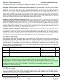
Thank you for choosing iSocket. Please take a few minutes to read through these
operating instructions carefully before using the product so that you can get full
advantage of the functionality and get maximum enjoyment from it. Pay special
attention to the safety instructions in Chapter 2! Incorrect use could affect your
guarantee or jeopardise health or property. We reserve the right to make design
changes on the device and its software without prior notice. Deviations not mentioned in
this instruction might exist in the software, which is considered acceptable and not
considered a defect. The latest version of these instructions can be found on our website
www.isocketworld.com. Be sure to read the terms of warranty before using the device,
so that you do not to lose your rights under the guarantee as a result of improper
operation (Chapter 18). You agree with the terms of warranty and limitation of liability
described in Chapter 18 when you purchase this product. Please keep these operating
instructions in a safe place for easy access when needed. We hope you thoroughly enjoy
using your iSocket.
NOTE!
The software supplied with this product is the exclusive property of
iSocket Systems. As an end-user you are granted a non-exclusive license
to use this software solely in combination with the device on which it is
installed and with which it is supplied. The license is non-transferable and
you do not have the rights to grant sublicenses.
Your iSocket device has a unique feature - " iSocket® Online 24/7" - that
gets the device back online even after a break in the GSM-network.
However the device needs a strong GSM signal in the area - it has an
internal antenna and may not operate efficiently if the signal in your area
is weak. Ensure that you have a strong GSM network before using the
device. Do not put metal or other conductive objects near the device - this
may cause signal loss. This product is designed for home and office use
only.
Different types of alerts that iSocket send you (power failure / power
restored / temperature rise /temperature fall / sensor triggered / etc.)
rely on the correct configuration of the mobile phone number for the
alerts – see Chapter 5.3.
This product uses a Lithium-ion battery and MUST NOT be used outside
the specified temperature! Please refer to technical information (Chapter
16) for detailed information about operating conditions and read the
safety instruction (Chapter 2) carefully.
If you wish to use the iSocket Power Notifier feature, plug in the device
for 10 hours before use. This will charge the built-in battery.
If you use a prepaid card you might be need to activate it first with your
cell phone network provider. More information is available from
www.isocketworld.com/prepaid/
iSocket® Environment Pro
www.isocketworld.com
Content
Content ............................................................................................................ 2
1. Device Description ......................................................................................... 3
2. Safety Instructions ......................................................................................... 5
3. Quick Start .................................................................................................... 7
4. Managing the iSocket Device ........................................................................... 8
4.1 Managing by SMS ...................................................................................... 8
4.2 Managing by Phone Call.............................................................................. 9
4.3 Manual Managing..................................................................................... 10
5. Security & Notifications Settings .................................................................... 10
5.1 Security Numbers List Settings .................................................................. 10
5.2 Password Protection ................................................................................. 11
5.3 Configuration of the Numbers for Alerts ...................................................... 11
6. Command Confirmation ................................................................................ 12
6.1 Confirmation of SMS-commands ................................................................ 12
6.2 Confirmation for Phone Calls ..................................................................... 12
6.3 Incorrect Commands, Later Configuration and Commands From Unauthorised
Users ........................................................................................................... 13
7. Measurement and Control of Temperature ....................................................... 14
7.1 Thermometer .......................................................................................... 15
7.2 Thermostat ............................................................................................. 15
7.3 Temperature Monitoring – Notifications, iSocket® Temperature Notifier .......... 16
8. Date and Time ............................................................................................. 17
9. Monitoring Rooms Using Sensors ................................................................... 18
9.1 iSocket Sensors ....................................................................................... 18
9.2 Sensor Activity Alerts - iSocket® Alarm Notifier ............................................ 19
9.3 Input/Output Relations ............................................................................. 20
9.4 Alarm Function ........................................................................................ 21
9.5 Alarm Logs ............................................................................................. 21
10. Scheduler .................................................................................................. 22
11. iSocket® Power Notifier & Status After Resumption of Power Supply ................. 22
12. Credit Information and Subscription Management (experimental) ..................... 23
13. Version Information .................................................................................... 23
14. Original Factory Settings ............................................................................. 23
15. LED Indicators ........................................................................................... 24
16. Technical Data ........................................................................................... 24
17. Troubleshooting ......................................................................................... 25
18. Limits of Warranty and Liability .................................................................... 26
19. Contacts.................................................................................................... 26
© Copyright iSocket Systems 2015
All rights reserved. Version 1.0.1-EN
-2-
English
iSocket® Environment Pro
www.isocketworld.com
1. Device Description
iSocket® Environment Pro is designed for remote monitoring of the environment in
your premises to give you peace of mind. This intelligent socket is controlled remotely by
SMS-commands via the GSM network. You can use either standard mobile phones (“old”
phones) or smartphones to manage and configure iSocket. It is also possible to carry out
some operations by a phone call. SIM-cards from most GSM-operators, including prepaid
cards, can be installed in iSocket.
The following aspects of the environment can be monitored with iSocket®.
Power monitoring. You will get an alert to your cell phone when the power fails
or is restored to your system. This is possible because the iSocket Environment Pro
has a built-in battery. You do not need to buy any extra accessories to activate this
feature.
Temperature monitoring. With a precision external sensor connected to iSocket
you can measure the temperature of almost any element: air, water, oil, solid
surfaces, etc. Information about temperature will be sent to your cell phone.
iSocket will notify you when the temperature rises beyond or falls below specified
levels. iSocket has a thermostat that turns equipment on and off according to your
settings. Unique features of iSocket® Smart Software will allow you to create an
advanced temperature monitoring system.
Security and safety monitoring. With a motion and/or door opening sensor
connected to the input of iSocket Environment Pro you can create a simple home
alarm system in a few minutes! An alert about a break-in will be sent to your cell
phone immediately. You may connect various logical sensors to the input of the
iSocket to monitor the safety environment to detect e.g. smoke (fire), water leaks
or gas leakage. The alert will be sent to your cell phone when something happens.
We manufacture pre-wired sensor sets for simple installation. You do not need
specific skills to configure these features. Please see Chapter 9 for more
information.
Remote switching and reboot. And of course iSocket supports remote switching and
reboot of equipment connected to it. You will definitely appreciate the elegant design of
iSocket with plugs and sockets suitable for many countries!
No service fee. We do not charge you monthly fees! You pay for the equipment once up
front and then you are free to choose subscriptions from your favourite GSM mobile
operator or to use prepaid (Pay-As-You-Go) cards.
Free of charge operations. Some operations (e.g. remote switching or reboot) can be
performed by a call to iSocket and you can configure them to be absolutely free! Thus
you may reboot your computer or modem remotely for free. See Chapter 4.2 and 6.2 for
details.
For more information about the technical characteristics of iSocket Environment Pro see
Chapter 16 and also visit our website www.isocketworld.com.
© Copyright iSocket Systems 2015
All rights reserved. Version 1.0.1-EN
-3-
English
iSocket® Environment Pro
www.isocketworld.com
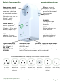
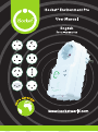
Main power socket
Socket for connecting
external electrical
equipment, which can
be controlled remotely.
Plug to connect
iSocket to the wall
socket to provide
power for device and
for connected
appliance.
(Figure shows
plug/socket type CEE 7/4
"Schuko", model
ISGSMT707EU).
POWER
Indicator of input
power from power
network.
Hidden button
Used to switch the
main socket manual
(Chapter 4.3) or reset
device (Chapter 14).
GSM
Status indicator for
GSM network.
OUT
Indicator of output
power for main socket.
Input for sensors
3.5mm jack, BLACK
(See Chapter 9)
NOT FOR
TEMPERATURE
SENSOR!
Additional information
about the indicators is
given in Chapter 15.
Socket for SIMcard (standard size
GSM SIM-card)
Socket for TEMPERATURE sensor
3.5mm jack, RED (See Chapter 7)
Warning! If you insert the temperature sensor to the wrong
jack, the temperature sensor will be destroyed!
Pictures below describe the plugs and sockets of other models.
Socket/Plug:
BS 1363
(British)
Socket/Plug:
NEMA 5-15
(North
America)
Socket/Plug:
CEE 7/5
(French)
© Copyright iSocket Systems 2015
All rights reserved. Version 1.0.1-EN
Socket/Plug:
AS/NZS 3112
(Australian)
-4-
Socket/Plug:
SEV 1011
(Swiss)
Socket/Plug:
CEI 23-50
S17/P17
(Italian)
Socket/Plug:
SI32 (Israeli)
English
iSocket® Environment Pro
www.isocketworld.com
2. Safety Instructions
This appliance complies with accepted technological standards with regard to safety.
Nevertheless, as manufacturers we consider it our obligation to make you aware of the following
safety information. To ensure years of trouble-free enjoyment, and to maintain your guarantee,
please note the following.
Never carry out repairs yourself! There are no serviceable parts in the device.
The operating voltage of the appliance and the mains voltage as well as the type of
current must match (see the rating plate on the underside of the appliance).
Only plug into a correctly installed earthed mains socket.
The device is not intended for direct plug-in equipment, which are not equipped with a
plug. External equipment that connects to the device must have a cord with appropriate
plug.
Some devices are supplied with their own switch, which needs to be disconnected before
they are unplugged. Do not use this product with such devices - it cannot disable the
switch of a remote device.
Do not use external equipment with a faulty plug!
Do not connect to appliances which cannot be left unattended (e.g. certain heaters)!
Do not exceed power load limit and other electrical parameters specified in the technical
characteristics. Check the power of the connected device!
The device is intended only for domestic private non-commercial use. Do not use in
emergency environments: e.g. military, hospitals etc!
This product is not designed for safe disconnection of the controlled equipment from
power network; the device is not equipped with a residual-current device (RCD). Make
sure that your home electrical network meets safety standards.
The product is designed for indoor use in dry area. Do not use it in wet or chemically
aggressive environments! For example, do not use it in the bathroom. It is also not
designed for industrial operation in aggressive environments.
Do not use this device if the casing is damaged!
Do not shake or drop the product. This could cause damage!
Keep away from direct sunlight.
Keep out of reach of children!
Block access to the management and set-up of the device to unauthorised users
(Chapter 5).
Read additional safety information in Chapter 18.
iSocket Systems hereby declares that this iSocket Environment Pro complies with the essential
requirements and other relevant provisions of Directive 1999/5/EC.
At the end of the product's useful life, please dispose of it at appropriate collection points
provided in your country.
NOTE: This equipment has been tested and found to comply with the limits for a Class B digital
device, pursuant to Part 15 of the FCC Rules. These limits are designed to provide reasonable
protection against harmful interference in a residential installation. This equipment generates,
uses and can radiate radio frequency energy and, if not installed and used in accordance with
the instructions, may cause harmful interference to radio communications. However, there is
no guarantee that interference will not occur in a particular installation. If this equipment does
cause harmful interference to radio or television reception, which can be determined by turning
the equipment off and on, the user is encouraged to try to correct the interference by one or
more of the following measures: reorient or relocate the receiving antenna; increase the
separation between the equipment and receiver; connect the equipment into an outlet on a
circuit different from that to which the receiver is connected; consult the dealer or an
experienced radio/TV technician for help.
© Copyright iSocket Systems 2015
All rights reserved. Version 1.0.1-EN
-5-
English
iSocket® Environment Pro
www.isocketworld.com
Safety Instructions for the Battery
This unit use a Li-ion battery. The safety instruction does not tell you how to maintain
the battery, because this battery is installed inside the unit. It is strictly prohibited to
replace the battery yourself - an authorised specialist must be consulted. However this
safety instruction does describe the care of units using a Li-ion battery.
Read all the safety information and instructions. Failure to comply with the
safety information and instructions may cause fire and / or serious injury.
We pay a great deal of attention to the design of every battery to ensure that we supply
you with batteries which offer maximum durability and safety. Despite all the safety
precautions, caution must always be exercised when handling devices with batteries.
Studies have shown that incorrect use and poor care are the main causes of the damage
caused by batteries. The following points must be obeyed at all times to ensure safe
use:
Don't throw battery or device with battery into an open fire. There is a risk of
explosion!
Always comply with the storage conditions (see Chapter 16)! Don't keep the
device with its battery in places where the temperature is liable to reach levels
outside those specified. In particular, do not leave the device in a car that is
parked in sunshine.
If the battery suffers overloading and/or overheating, the integrated protective
cut-off will switch off the charging/discharging for safety reasons. If this happens
you will not be able to get a power failure alert. Using the battery at temperatures
outside those specified in the technical information (Chapter 16) will cause
chemical damage and may cause a fire.
In the event of incorrect use, fluid may escape from the battery. Avoid contact
with this fluid. If you touch it by mistake, rinse the affected area with water. If
you get the fluid in your eyes, seek medical advice. Stop using the device if fluid is
coming from it!
Li-ion batteries are subject to a natural ageing process. The battery must
absolutely be replaced when its capacity falls just 80% from the capacity as new.
A weak, old battery is no longer capable of meeting the high power requirements
and therefore poses a safety risk.
Exhaustive discharge will damage the battery. The most common cause of
exhaustive discharge is lengthy storage or non-use of a partly discharged battery.
Don't allow the device to be stored for a long time without use. Never use a
battery-driven device if you suspect that the last time the battery was charged
was more than 12 months ago. There is a high probability that the battery has
already suffered dangerous damage (exhaustive discharge).
Rechargeable batteries contain materials that are potentially harmful to the
environment. Batteries may not be disposed of with normal domestic waste. You
should dispose of used batteries at your local collection point.
© Copyright iSocket Systems 2015
All rights reserved. Version 1.0.1-EN
-6-
English
iSocket® Environment Pro
www.isocketworld.com
3. Quick Start
Quick Start comprises three simple steps:
Step 1. Install SIM-card.
You need a standard size SIM-card from a GSM-operator to be installed in the unit. If
you use a prepaid card you might need to activate it first with an unlocked GSM cell
phone. More information is available from www.isocketworld.com/prepaid/
Install SIM-card into the special slot and push until fixed (you will hear a click). SIM-card
orientation is shown on the front side of the device. Do not insert or eject the SIM-card
on a running device! Switch off the device before you insert or eject SIM-card. Do not
use SIM-cards that contain messages! Remove all messages from the SIM-card. Do not
use SIM-cards with NFC chip embedded in a SIM (chip for payments from mobile phone).
NOTE! You must disable PIN-code authorisation for the SIM-card! You can only disable
PIN authorisation by using mobile phone that support standard size SIM-card. Insert the
SIM-card into mobile phone and disable PIN usage using the phone menu. You can find
more information in the manual for the phone or ask assistance from the shop, where
you purchased the mobile subscription. If you have forgotten to disable PIN-code the
GSM indicator will be blinking every second and the POWER and OUT indicators will
signal this by specific blinks (see Chapter 15). The same blinking can occur when the
SIM-card is not inserted correctly or is damaged.
Step 2. Apply power to the device.
Connect iSocket to a wall socket. POWER and OUT indicators blink three times
simultaneously. If everything is functioning correctly the POWER indicator will be a
constant light green. The GSM indicator blinks once a second during network search and
every 3 seconds when the network has been found. More information about the
indicators in Chapter 15.
Step 3. Execute your first command and make yourself the main user.
Your device with iSocket® Smart Software has the unique feature "Make Me Boss!". Send
SMS-command MAKEMEBOSS to the phone number of the SIM-card installed in the unit
and it will automatically assign the phone number from which you have sent it as the
number for all types of alerts and will also enable protection by the list of phone numbers
and will add the number to the list.
NOTE! Make sure that you don't use the "hide my number" option for the number from
which you execute the command. If the system cannot recognise the number it will not
add it to the number for alerts and to the security list. Alternatively you can use the
methods of adding these numbers which is described in Chapter 5.1 (for SECNUMBER)
and 5.3 (for ALERTNUMBER). Please also read the IMPORTANT NOTE in Chapter
5.1 about the specific requirements of some mobile networks!
First test.
The device is now ready to work! You can carry out a simple test. Connect an appliance
to the iSocket, e.g. a desk lamp (don't forget to turn on the lamp switch). Send the
message ON to the SIM-card number and the lamp will switch on. Send the message
OFF and the lamp will turn off. Remove the iSocket from the wall-socket. You will soon
get a power failure alert!
© Copyright iSocket Systems 2015
All rights reserved. Version 1.0.1-EN
-7-
English
iSocket® Environment Pro
www.isocketworld.com
4. Managing the iSocket Device
You can manage the device with SMS-commands, by phone call or manually. SMS
management offers more options.
4.1 Managing by SMS
Commands are sent in form of SMS messages to the SIM-card number of the iSocket.
Messages have the following syntax:
COMMAND
(for example, STATUS).
If a password was configured (see Chapter 5), then you must use following syntax:
passwordCOMMAND
(for example, 12345STATUS), where 12345 is a password set by the
command PASSWORD=12345 (more details in Chapter 5).
Commands are not case sensitive. There are three types of commands on device:
1. Configuration commands (marked "Conf" in the tables).
These commands configure some parameters on the device and usually (not always)
have the syntax COMMAND=VALUE, so they have symbol "=" after the command name.
The configuration can only be performed within 30 minutes after device has been
powered on or after the last configuration command has been received. If you try to
configure device after 30 minutes, then you will get the message "command – Time for
configuration expired (Conf)!" (only if ERROR=ON - see Chapter 6). To disable this
limitation you must configure security on device – see Chapter 5. Settings are stored
in non-volatile memory and are not lost when power is off. Each configuration
command has a default value. This is the value that was installed at the factory (for
details see Chapter 14).
2. Information commands (marked "Inf" in the tables).
These commands inform you about different statuses of the device or about other
corresponding statuses, so they have information nature. If a command has a question
mark at the end (COMMAND?), then this command will inform you about current value
of the parameter, which has the same name as the command. These commands are
available at any time. Should a configuration command have different values these will
all be seen in response to the information command associated with this configuration
command. The values will be comma-separated and the current active value will be
indicated in parentheses. For example, you send the information command
"COMMAND?". In response you will get the reply "COMMAND=VALUE1,(VALUE2)". This
means that the current active value is "VALUE2", and "VALUE1" is another value
acceptable for this command. This syntax is made for your convenience - you do not
need to refer to the manual each time when to remember all possible values. They will
be given in the response. The first value in the response is the factory default value (see
Chapter 14).
3. Control and management commands (marked "Ctrl" in the tables).
Used to control the iSocket device - perform some active action. They are not limited by
configuration window and can be used at any time.
You will get a response after sending the commands. This can be disabled if desired (see
Chapter 6). If you make a mistake in the command and send an incorrect command,
you will receive a message "COMMAND - No such command exists on the device!" (Only
© Copyright iSocket Systems 2015
All rights reserved. Version 1.0.1-EN
-8-
English
iSocket® Environment Pro
www.isocketworld.com
if ERROR=ON - see Chapter 6). If a command longer than 30 characters was sent, it will
be deleted without any response notifications.
The list of simple commands for management and configuration is shown in the
following table. The real response may differ from those indicated in the table,
depending on the command.
Command
ON
OFF
ON30
Description
Turn on main power socket
Turn off main power socket
Turn on main power socket for 30 seconds.
Maximum value is 65000 seconds.
OFF30
Turn off main power socket for 30 seconds.
Maximum value is 65000 seconds.
RESTART
Restart (return to the same status after a certain
period of time) main socket. Time for restart set
by RESTARTTIME.
RESTARTTIME=5 Configures time (in seconds) for RESTART
command. Maximum value is 600 seconds.
RESTARTTIME?
Informs about RESTARTTIME value
STATUS
Request for main power socket status,
temperature, GSM signal, date, sensor's status.
TEMPERATURE
RUNTIME
Response
Power socket ON
Power socket OFF
Power ON for 30 seconds
Type
Ctrl
Ctrl
Ctrl
Power OFF for 30 seconds
Ctrl
Power socket restarted
Ctrl
RESTARTTIME=5 – OK
Conf
RESTARTTIME=5 seconds
Power socket ON
Signal: Good (-67dBm)
TEMP: 25C(77F)
ALARMF: Disabled
ALARM status: No act
Time: y/m/d,h:m:s
TEMPERATURE: 25C(77F)
Inf
Ctrl
Informs about temperature. See details in Chapter
7.
Informs how long main power socket has been
Power socket is ON from:
turned on (since last restart or power on). If you
y/m/d,h:m:s
turn on the main socket manually before the
correct date was installed on the device, the startup time of the device will not be recorded correctly.
Ctrl
Ctrl
4.2 Managing by Phone Call
The main socket for external electrical equipment can also be managed by mobile or
landline phone. For example, you can call to the phone number of the SIM-card in the
device and the equipment connected to the device (e.g. modem) will be restarted. After
a call to iSocket the action occurs immediately. The action must be pre-configured. There
is no action configured by default. Keep in mind that you are not able to configure the
active actions if the security number list (Chapter 5.1) is not configured. This is because
the password protection is not available for calls, so anyone can call to the SIM-card
number if there is no security numbers list protection and this call may cause unwanted
reboot. Accordingly, if you are going to disable the security numbers list protection, then
the option RING goes into the value "NOACTION" automatically.
In response to the activating call the device will send you a message. You can configure
a call response instead of an SMS. Read more about this in Chapter 6.2. The following
table indicates which actions can be pre-configured.
Command
RING=SWITCH
RING=RESTART
RING=NOACTION
RING?
Description
Switching (changing status to negative) main power
socket by phone call
Restart (return to the same status after a certain
period of time) main socket by phone call. Time for
restart set by RESTARTTIME.
Ignore phone calls
Informs what action configured
© Copyright iSocket Systems 2015
All rights reserved. Version 1.0.1-EN
-9-
Response
RING=SWITCH – OK
SECLIST is not active!
RING=RESTART – OK
SECLIST is not active!
Type
Conf
RING=NOACTION – OK
RING=(NOACTION),
RESTART,SWITCH
Conf
Inf
Conf
English
iSocket® Environment Pro
www.isocketworld.com
4.3 Manual Managing
The main power socket can be managed manually. You can switch it manually by a
hidden button which is on the front panel next to the logo. The button can be activated
with a suitable thin mechanic tool. Pressing this button switches the main power socket
to a negative value. So, if it was turned off, it will be turned on and vice versa.
Would you like to see more features? You are welcome to send us your
feedback: http://www.isocketworld.com/feedback/
5. Security & Notifications Settings
Block access to iSocket management for unauthorised users! If there are no security
settings, then anyone who knows the phone number of the SIM-card will be
able to manage the device and deplete the card's credit - which is not
advisable! The device uses two methods of protection against unauthorised access:
Only allowing access to authorised phone numbers
Authentication by password
Both methods can be used separately or together. In the first method the device ignores
SMS-commands and calls from numbers that are not listed. The list can contain up to 10
numbers. The second method involves the use of individual 5-characters password. This
password must be typed before the SMS-commands without any space or special
characters as shown here:
passwordCOMMAND
(for example, 12abcSTATUS), where 12abc is a password set by the
command PASSWORD=12abc (more details below).
5.1 Security Numbers List Settings
The security list allows you to configure up to 10 numbers and up to 15 digits for one
phone number. Below is a list of commands that explain how to activate the security list
and how to add a number. By default, the security list is disabled and does not contain
any numbers. The first number can be added in a simple way by executing command
MAKEMEBOSS - see introduction to this feature in the "Quick Start" (Chapter 3, Step 3).
However all the next numbers must be added using the command SECNUMBER+,
described in the table below, because all the next numbers from which you try to
execute the MAKEMEBOSS command will already be treated as non-authorised.
Command
MAKEMEBOSS
SECNUMBER+35
89123456789
SECNUMBER3589123456789
SECNUMBER-ALL
SECNUMBER?
SECLIST=ON
SECLIST=OFF
SECLIST?
Description
This will add the number from which you
send message to the list and will enable
security list (SECLIST=ON will be active),
also it will add your number for all types
of other alerts (Chapter 7.3, 9.2 and 10)
Add new number to security list
Delete specific number from security list
Delete all numbers from the list
Request for security list numbers
Activate security list
Disable security list
Information about security list activation
© Copyright iSocket Systems 2015
All rights reserved. Version 1.0.1-EN
- 10 -
Response
Your phone number has been
assigned for all types of alerts
and was added to security list
which has been activated
Type
Conf
SECNUMBER+3589123456789 –
OK
SECNUMBER-3589123456789 –
OK
SECNUMBER-ALL – OK
SECNUMBERs: 3589123456789,
3589000000555
SECLIST=ON – OK
SECLIST=OFF – OK
SECLIST=OFF,(ON)
Conf
Conf
Conf
Inf
Conf
Conf
Inf
English
iSocket® Environment Pro
www.isocketworld.com
Telephone numbers must be added in international format (with country code)
without spaces or hyphens!
Here are two UNITED STATES examples of how to add and remove number 5555555:
SECNUMBER+12125555555 – example of adding number
SECNUMBER-12125555555 – example of removing number
Here 1 is the United States country code, 212 is the city code for New York and 5555555
is a 7-digit local number.
IMPORTANT NOTE! Some mobile operators indicate international numbers when transmitting
SMS’s (in our example 12125555555), but during the call such operators indicate number in
local format (in our example it will be 2125555555 or even 5555555). If such behaviour was
noticed in your mobile network you have to add both international and local numbers to the
list! It means in addition to the international number you must also add the local number by the
command SECNUMBER+2125555555 or/and SECNUMBER+5555555.
If you add a number to the list when
disabled. Do not forget after adding
SECLIST=ON. If you deleted all the
protection will be disabled automatically
the list is not activated, the protection will be
number to activate security list by command
numbers by command SECNUMBER-ALL, the
(SECLIST=OFF became active).
Make sure that you don't use the "hide my number" option. All numbers that the system
does not recognise are considered to be unauthorised numbers.
We suggest that you always use security list protection, even if you use
password protection. Chapter 6.3 lists more reasons for this.
5.2 Password Protection
The following table shows how to set a password for managing access. The password
must consist of 5 characters. Do not use a simple combination of numbers for a
password! Password 12345, 11111, abcde and other such passwords are not secure!
NOTE! Don't forget to add the old password before the command PASSWORD=x
if you are going to remove password protection or update the password.
Command
PASSWORD=12abc
PASSWORD=NO
Description
Set password 12abc
Disable password
Response
PASSWORD=***** – OK
PASSWORD=NO – OK
Type
Conf
Conf
5.3 Configuration of the Numbers for Alerts
Before enabling different alerting (Chapter 7.3, 9.2 and 10) you must setup at least one
number for alerts. There are few optional ways to setup this number. One is the feature
"Make me boss!" (see introduction in the "Quick Start", Chapter 3, Step 3 and more in
Chapter 5.1). Another option is the feature "Alert me!" – send the command ALERTME
from the number which you want to be the number for alerts and the system will
automatically assign the phone number from which you have sent it as the number for
all types of alerts. You can send ALERTME from any number which is included on the
security list (Chapter 5.1). You can also use the command ALERTNUMBER+ to add a
number for alerts manually (see description in the table below).
© Copyright iSocket Systems 2015
All rights reserved. Version 1.0.1-EN
- 11 -
English
iSocket® Environment Pro
www.isocketworld.com
NOTE! Make sure that you don't use the "hide my number" option for the number from
which you execute the command ALERTME and make sure that the number is in the
security list. If the system cannot recognise the number or if the number is not
authorised it will not add it to the number for alerts.
Command
Description
Response
Type
ALERTME
This will automatically add the number from
which you send the message to the list for all
types of other alerts.
Set the number for alerts manually.
Instructions how to add a number are similar
to those given in Chapter 5.1 (see examples
there). DO NOT ADD THE PHONE NUMBER IN
LOCAL FORMAT - USE THE FULL
INTERNATIONAL NUMBER ONLY (WITH
COUNTRY CODE).
Remove number from list
Your phone number has
been assigned for all
types of alerts!
ALERTNUMBER+358912
345678 – OK
Conf
ALERTNUMBER+358
912345678
ALERTNUMBER3589123456789
ALERTNUMBER-ALL
ALERTNUMBER?
Remove all numbers
Information about numbers
Conf
ALERTNUMBER Conf
3589123456789 – OK
ALERTNUMBER-ALL – OK Conf
ALERTNUMBERs:
Inf
3589123456789,
3589223456789
NOTE! Do not keep wrong or non-existent numbers in the list of ALERTNUMBERs! Do
not keep numbers in local format in the list of ALERTNUMBERs, use only the international
format (with country code). Ignoring this advice will delay alerts to good numbers.
6. Command Confirmation
It is important to confirm that the command was executed successfully. For this purpose
we have implemented notifications of each executed command. If you wish to receive
execution confirmations the setting “hide my number” should not be activated on the
phone from which you are sending messages or making calls to iSocket.
6.1 Confirmation of SMS-commands
If you activate this notification, you will be informed about each command execution. It
is the default setting, but you can disable these notifications to save the cost of SIM-card
messages.
Command
SMSCONFIRM=ON
SMSCONFIRM=OFF
SMSCONFIRM?
Description
Response messages to SMS-commands will be
sent
Do not send response messages to SMScommand
Information about SMSCONFIRM configuration
Response
SMSCONFIRM=ON – OK
Type
Conf
SMSCONFIRM=OFF – OK Conf
SMSCONFIRM=ON,(OFF) Inf
The next commands are not affected by the SMSCONFIRM setting due to the specific
nature of the commands: STATUS, TEMPERATURE, RUNTIME, SHOWALARMLOG, CREDIT,
HARDWARE, SERIALNUM, FIRMWARE, DATE and all information commands ("Inf").
6.2 Confirmation for Phone Calls
When managing by phone call, your command will be also confirmed by return SMS, but
you can configure the device to call back to the mobile phone instead of sending SMS. In
this case iSocket will call to your phone within about 10 seconds and then hangs-up. So,
SIM-card credit will not be spent. This allows you to perform reboot or switch operations
free of charge!
© Copyright iSocket Systems 2015
All rights reserved. Version 1.0.1-EN
- 12 -
English
iSocket® Environment Pro
Command
RINGCONFIRM=SMS
RINGCONFIRM=CALL
RINGCONFIRM=OFF
RINGCONFIRM?
www.isocketworld.com
Description
Send response SMS after call to device
iSocket call back to your phone within
10 seconds and then hang-up
Don't notify results after phone call to
the device
Information about RINGCONFIRM
configuration
Response
RINGCONFIRMTYPE=SMS - OK
RINGCONFIRMTYPE=CALL - OK
Type
Conf
Conf
RINGCONFIRM=OFF – OK
Conf
RINGCONFIRM=(SMS),CALL,OFF
Inf
6.3 Incorrect Commands, Later Configuration and Commands From
Unauthorised Users
If an incorrect command was sent to the device (typo mistake, for example), you will get
the "command - No such command exists on the device!" response. If you have
password protection, but forgot to specify it before command (see Chapter 5.2), you will
get the "Invalid access password!" response. If you are trying to assign an invalid value
to the configuration command, you get the message "Incorrect value!". You will get
"Time for configuration is expired (Conf)!" response when you try to send a configuration
command after the configuration time is up (see Chapter 4). If an unexpected error
occurred during the command execution you will get the message "Execute error!". You
can disable all the above error messages by setting options ERROR=OFF.
If the security list was configured (see Chapter 5.1) and someone tries to execute a
command no response will be received until you install SMSCONFIRMUNAUTH=ON. If you
set "ON" value for this parameter, then unauthorised numbers will receive the message
"Access deny!" in response to an attempt to execute any command. We do not
recommend you to set "ON" value for this option, because unauthorised users
who know the phone number of the SIM-card can deplete the card's credit with
such response messages. Therefore, we also strongly suggest using protection
with security list (Chapter 5.1), and not just password protection! This is due to
the fact that a command typed without a password is considered an incorrect command
and the illegal sender will receive "command - No such command exists on the device!"
in response. And he can also deplete SIM-card credits by such responses.
Command
ERROR=ON
ERROR=OFF
ERROR?
SMSCONFIRMUNAUTH=ON
SMSCONFIRMUNAUTH=OFF
SMSCONFIRMUNAUTH?
Description
Activates sending of information SMS for
each received SMS command, which was
not executed due to any error.
Disable the error messages responses
Information about ERROR configuration
Send reports (errors, not permitted, time
out) to unauthorized numbers
Don't send reports to unauthorized
numbers
Information about SMSCONFIRMUNAUTH
configuration
Response
ERROR=ON - OK
Type
Conf
ERROR=OFF - OK
ERROR =(ON),OFF
SMSCONFIRMUNAUTH
=ON – OK
SMSCONFIRMUNAUTH
=OFF – OK
SMSCONFIRMUNAUTH
=(OFF),ON
Conf
Inf
Conf
Conf
Inf
Generally, it should be noted that the ERROR=OFF command disables all reports about
errors and later configuration for all senders. By default, this option is set to "ON", so
that during the familiarisation period you can get all responses about errors and will not
be confused when there is no response from the device. Once you are familiar with the
device, you can then disable the error message responses. In the beginning however, we
strongly recommend configuring the list of allowed numbers (Chapter 5.1) and keeping
the option SMSCONFIRMUNAUTH, which is set to OFF by default.
© Copyright iSocket Systems 2015
All rights reserved. Version 1.0.1-EN
- 13 -
English
iSocket® Environment Pro
www.isocketworld.com
7. Measurement and Control of Temperature
iSocket Environment Pro supports one external digital temperature sensor that can
measure the temperature of different elements (air, liquid, solid, etc) from -55C(-67F)
to 120C(248F) with an accuracy of ±0.5˚C. You can buy sensors with different lengths
of cable from us. Sensors are waterproof. The sensor must be connected to the RED
3.5mm jack socket on the rear of device.
Short sensor to measure temperature near
a device. Can be a good option if you want
to monitor the temperature just inside a
room. No messy cables. (Model: ITS00J).
Sensor with long cable, e.g. 3m (10ft). Can
be a good option to measure temperature
outside, or temperature of a liquid or some
surface. The probe has a “wing” for
screwing. A sensor with a long cable is also
a good option if the iSocket unit is located
close to the heating system, which may
affect temperature measurements. A
sensor with a cable will allow you to install
the sensor far from the source of heating
in that case and you can measure the
temperature at precisely the point you
want: e.g. ceiling, floor or in the middle of
room. (Model: ITS30J).
IMPORTANT NOTES!
Do not insert the temperature sensor to the black 3.5mm jack, which is
input. The temperature sensor will be damaged by 12V coming from this
input!
Do not insert or remove the temperature sensor on a running device! Switch off
the device before you insert or remove the temperature sensor.
If the sensor shows 85C, 127C or 0C when the temperature is obviously different
from these values, it might be a sign that the sensor is not properly inserted or is
damaged.
NOTE! Check that the sensor is inserted
into the 3.5mm red jack socket to the very
end. The connection is taught and you
have to ensure that there is no gap
between the connector of the sensor and
the jack socket!
© Copyright iSocket Systems 2015
All rights reserved. Version 1.0.1-EN
- 14 -
English
iSocket® Environment Pro
www.isocketworld.com
7.1 Thermometer
The external temperature sensor measures the temperature of the environment in the
particular area where it is installed and iSocket can provide this information via SMS.
Information about the temperature can be available immediately the sensor is connected
to iSocket. Information available in Celsius and Fahrenheits.
Command
TEMPERATURE
STATUS
Description
Informs about temperature in the room
Request for socket's status and temperature
information includes
Response
TEMPERATURE: 25C(77F)
Power socket OFF
…
TEMP: 25C(77F)
Type
Ctrl
Ctrl
7.2 Thermostat
iSocket® Smart Software has an advanced thermostat feature that allows you to control
both heating and cooling systems with a wide choice of settings and be very simple in
the same time.The thermostat feature allows you to control the main power socket and
change it depending on the pre-configured “switch-off” temperature. The interval
between temperature readings from sensors is one minute.
Command
THERMOSTATON
Description
Activate thermostat
THERMOSTATOFF
Disable thermostat
THERMOSTAT=
HEATING
Set the condition of thermostat. Use
this value if heating system is
connected to device
THERMOSTAT=
COOLING
Set the condition of thermostat. Use
this value if cooling system is
connected to device
SWITCHOFFTEMP=10C
Set the temperature for turning off
the main socket when thermostat
enabled. Values from -55C to 120C,
or from -67F to 248F. Do not forget
to type C (means Celsius) or F
(means Fahrenheits) after the value.
Only integer values must be used!
Please only use
even numbers for Fahrenheit
temperatures.
Information about thermostat
configuration
or
SWITCHOFFTEMP=50F
THERMOSTAT?
Response
THERMOSTATON – OK
THERMOSTAT=HEATING
Switch-off temperature:
10C(50F)
Note! Thermostat is working
now!
THERMOSTATOFF – OK
Note! Thermostat was disabled!
THERMOSTAT=HEATING – OK
Switch-off temperature:
10C(50F)
THERMOSTAT: Disabled
THERMOSTAT=COOLING – OK
Switch-off temperature:
22C(72F)
THERMOSTAT: Enabled
SWITCHOFFTEMP=10C(50F) –
OK
THERMOSTAT=HEATING
THERMOSTAT: Disabled
Type
Ctrl
THERMOSTAT: Enabled
THERMOSTAT=HEATING
Switch-off temperature:
10C(50F)
Inf
Ctrl
Conf
Conf
Conf
Do you particularly agree, or disagree with anything in our software?
Give us your opinion: http://www.isocketworld.com/feedback/
© Copyright iSocket Systems 2015
All rights reserved. Version 1.0.1-EN
- 15 -
English
iSocket® Environment Pro
www.isocketworld.com
Example of heating system control. A typical example of temperature control would be
heating activation in remote area if the temperature drops below 10C (50F). The following
settings must be used: THERMOSTAT=HEATING, SWITCHOFFTEMP=10C
(or SWITCHOFFTEMP=50F), THERMOSTATON. With these settings the thermostat will keep the
temperature in the range of about 10C (50F). This means that as soon as the room is heated up
to 10C (50F) the main socket is turned off. If the current temperature in the room is over 10C
(50F) the main socket does not turn on until the temperature drops below 10C (50F).
Example of cooling system control. Another example is air conditioning activation when the
temperature exceeds 22C (72F): THERMOSTAT=COOLING, SWITCHOFFTEMP=22C (or
SWITCHOFFTEMP=72F), THERMOSTATON. This means that as soon as the room is cooled to 22C
(72F) the main socket is turned off. If current temperature in the room is less than 22C (72F)
the main socket does not turn on until the temperature rises above 22C (72F).
7.3 Temperature Monitoring – Notifications, iSocket® Temperature
Notifier
Before enabling alerts you must set up at least one number for alerts – see Chapter 5.4.
There are several type of alerts related to temperature in iSocket Smart Software
installed on your iSocket Environment Pro: switch-off alert (SWITCHOFFALERT),
temperature fall alert (TFALLALERT), temperature rise alert (TRISEALERT), and alert
when temperature sensor has failed (TSENSFAILALERT).
SWITCHOFFALERT - enable SMS sending when “switch-off” temperature is reached
and a relay was therefore deactivated. This just allows you to know that main power
socket was switched off and shows at which temperature this happened. This feature is
related with thermostat and works only if thermostat is enabled. Note! It will send an
alert every time the “switch-off” temperature was reached, so this event could be too
often during the work of thermostat. We do not recommend to enable this alert!
TSENSFAILALERT - send alert if some temperature sensor has failed or a reading
problem occurred on an active temperature sensor. Only one alert will be sent until you
change something in thermostat settings and some new failure occurred. If a
temperature sensor has failed, then the thermostat will remain activated, but will not
operate.
These two types of alert are related to the thermostat and work only if thermostat is
enabled.
NOTE! When a thermostat was deactivated because of temperature sensor failure or
when you disable a thermostat manually, the relay will remain in the same condition as
it was just before thermostat was disabled. This means that disabling the thermostat
won't change the previous status of relay and you must do it yourself if you need to.
iSocket® Temperature Notifier - a feature of the iSocket device which notifies you in
the event of the room temperature falling below (TFALLALERT) or rising above
(TRISEALERT) critical levels. This is another type of temperature alert which your
iSocket can provide for you. This feature does not affect the thermostat and can work
independently. This feature is not related to output, but to temperature sensors
connected to the unit. If you need to know when the temperature drops below the
specified level, set TFALLALERT. If you need to know when the temperature exceeds
the specified value, set TRISEALERT.
© Copyright iSocket Systems 2015
All rights reserved. Version 1.0.1-EN
- 16 -
English
iSocket® Environment Pro
Command
SWITCHOFFALERT=ON
SWITCHOFFALERT=OFF
SWITCHOFFALERT?
TSENSFAILALERT=ON
TSENSFAILALERT=OFF
TSENSFAILALERT?
TRISEALERT=35C
or
TRISEALERT=96F
TRISEALERT=OFF
TRISEALERT?
TFALLALERT=15C
or
TFALLALERT=60F
TFALLALERT=OFF
TFALLALERT?
www.isocketworld.com
Description
Enable SMS sending when
SWITCHOFFTEMP is reached and main
socket is therefore deactivated. Works
only if thermostat is enabled.
Disable above alert
Show current settings for
SWITCHOFFALERT
Enable sending alerts if some
temperature sensor failed.
Disable failed alerts
Show current settings of
TSENSFAILALERT
Set the temperature at which you
should receive a temperature rise alert.
Values from -55C to 120C, or from 67F to 248F. Do not forget to type C
(means Celsius) or F (means
Fahrenheits) after value. Only integer
values must be used! Please only use
even numbers for Fahrenheit
temperatures.
Disable temperature rise alert
Show current settings for TRISEALERT
Set the temperature at which you
should receive a temperature fall alert.
Values from -55C to 120C, or from 67F to 248F. Do not forget to type C
(means Celsius) or F (means
Fahrenheits) after value. Only integer
values must be used! Please only use
even numbers for Fahrenheit
temperatures.
Disable temperature fall alert
Show current settings for TFALLALERT
Response
SWITCHOFFALERT=ON – OK
Type
Conf
SWITCHOFFALERT=OFF – OK Conf
SWITCHOFFALERT=(OFF),ON Inf
TSENSFAILALERT=ON - OK
Conf
TSENSFAILALERT=OFF - OK
TSENSFAILALERT
=(ON),OFF
TRISEALERT=35C(96F) – OK
Conf
Inf
TRISEALERT=OFF – OK
TRISEALERT=35C(96F)
TFALLALERT=15C(60F) – OK
Conf
Inf
Conf
TFALLALERT=OFF – OK
TFALLALERT=15C(60F)
Conf
Inf
Conf
8. Date and Time
Date and time are used for logging alarms (Chapter 9.3) and to configure the scheduler
(Chapter 11). The date can also be seen in the STATUS response.
The device automatically sets the date as soon as you start to use it. No action is
required! However, if for some reason at the beginning of the operation an incorrect
date or time was set, and then set it again manually or automatically. Automatic
date/time settings are based on the GSM operator's network date/time. The device
saves date and time settings for several hours after a power failure.
Command
DATESMS
Description
This message is automatically set with the date
based on time taken from the SMS
DATE=yy/mm/dd,hh Manually set the date and time
:mm:ss+zz
zz – is GMT time zone
DATE
Request for actual date and time in device
Response
DATE yy/mm/dd,
hh:mm:ss+zz – OK
DATE=yy/mm/dd,
hh:mm:ss+zz – OK
DATE yy/mm/dd,
hh:mm:ss+zz
Type
Conf
Conf
Ctrl
Would you like to see more features or is there something in our software or
documentation that you dislike? You are welcome to send us your feedback!
http://www.isocketworld.com/feedback/
© Copyright iSocket Systems 2015
All rights reserved. Version 1.0.1-EN
- 17 -
English
iSocket® Environment Pro
www.isocketworld.com
9. Monitoring Rooms Using Sensors
With iSocket Environment Pro you can set up security or safety monitoring of your
premises. You can connect various sensors: motion sensor, door opening detector,
smoke detector, water sensor, etc on the input (black 3.5mm jack) of your iSocket.
Notification will be sent to your cell phone when the sensor is activated. Both N/C and
N/O types of sensors are supported. The output can also be controlled by input: you can
set up a particular time for which main power socket should be switched on or off when a
sensor is activated. This allows you to activate external equipment, which will behave
according to your specific environment (e.g. pump will start to drain water when the
water sensor detects a signal or a siren will be activated when door movement is
detected). Unique iSocket® Smart Software installed on your iSocket provides plenty
options for configuration, which allows you to create a really advanced, but at the same
time, simple system.
This section only provides brief explanations needed for a specialist to configure the
device and not a detailed explanation. If you do not have the required skills, then ask for
help from a specialist. The features described in this section are supplementary options
only and should not be considered a substitute for professional security systems.
Nevertheless, at a reasonable cost you can set up simple protection for your home or
office, because we sell ready-to-go pre-wired sensors kits with detailed connection
instructions.
9.1 iSocket Sensors
Sensors are not supplied with the device. These can be bought directly from us or our
dealer network. Our wired sensor kits have several benefits compared to wireless
solution. The most important of them are:
high reliability, because of the reliable wired connections that use special
professional copper alarm-grade cable;
high security, because the connection cannot be interrupted by wireless scanners;
maintenance free, because you do not need to check and change batteries.
KIT1 for burglar
alarm
(Model: ISKIT1)
KIT2/KIT3 for fire
KIT4 for gas
alarm
leak alarm
(Models: ISKIT2/ISKIT3) (Model: ISKIT4)
iSocket Water
Sensor for water
leak alarm
(Model: ISWSNO1)
Splitter for
connecting several
sensors in parallel
(SPLIT2W15CM)
Refer to our website www.isocketworld.com for up-to-date information about the sensors
we have for your iSocket.
Command
SENSORTYPE=NO
SENSORTYPE=NC
SENSORTYPE?
Description
The value depends on the sensor type. Set
this value if the sensor is N/O type.
The value depends on the sensor type. Set
this value if the sensor is N/C type.
Information about SENSORTYPE configuration
© Copyright iSocket Systems 2015
All rights reserved. Version 1.0.1-EN
- 18 -
Response
SENSORTYPE=NO – OK
Type
Conf
SENSORTYPE=NC – OK
Conf
SENSORTYPE=(NO),NC
Inf
English
iSocket® Environment Pro
www.isocketworld.com
IMPORTANT NOTES!
Do not insert alarm sensors to the red 3.5mm jack, which is the socket for the
temperature sensor only!
Do not insert or remove sensors on a running device! Switch off the device before you
insert or remove sensors.
Check that the sensor is inserted to the 3.5mm black jack socket to the very end.
Connection is taught and you have to ensure that there is no gap between connector of
sensor and jack socket, otherwise you may receive false alarms.
You can connect several sensors in parallel, but the sensors will not be recognised
individually.* All sensors must be configured as N/O in this case – see table below and
follow instruction supplied with specific sensor.
The total power consumption of the sensors connected should not exceed 300mA.*
We recommend that you only use approved sensors purchased from us, failing which we
will not be held responsible for the operation of the device.
* If you intend to install many different sensors we would recommend you take a look at
our professional equipment from iSocket Smart House family on www.isocketworld.com,
e.g. iSocket Smart Relay.
9.2 Sensor Activity Alerts - iSocket® Alarm Notifier
iSocket® Alarm Notifier - a feature of the iSocket device which will notify you in the
event of a break-in and some other case when sensor was activated. You can receive
notifications in various ways. iSocket Environment Pro can call you or send an SMS when
the sensor is triggered. You can also be informed by SMS on each change of sensor's
status (change of logical value). To enable such notifications you must setup at least one
number for alerts (see Chapter 5.3). Place the most important numbers for notifications
at the beginning of the list. Read below to understand the reason.
Notification cycle logic. If you have configured notifications by messages the device will
send messages to all numbers. If call alerts are configured, the device will call you within
about 20 seconds. If you answer (pick up the handset) within these 20 seconds, the callnotification cycle is considered complete and no one else from the list receive call or
message. Thus, by answering the call you will stop the notification cycle. That means that
you are aware of the alarm event and must act accordingly. If you don't answer or if you
drop the call (hangs up), after 20 seconds the device will try to reach the next number on
the list. The device will only try to call each number once. The call-notification cycle is
considered complete as soon as someone answers. If no number is answered during the
call-cycle, the device will send messages to all alert-numbers, thus completing the
notification cycle. SMS-notification cycle is considered complete as soon as all messages
have been sent by the device. Therefore the most important numbers for notifications have
to be placed at the beginning of the list.
Alarm detection and alerting logic. Only one alarm within 60 seconds is indicated. This
means that if two (or more) sensors were activated within one minute, you will only get the
one alert. During the notification cycle the device will not detect new sensor triggering. The
device will be ready to detect sensor activity no later than one minute after completion of
the notification cycle. If the sensor is still active at this time the device will start a new
session of notifications.
© Copyright iSocket Systems 2015
All rights reserved. Version 1.0.1-EN
- 19 -
English
iSocket® Environment Pro
www.isocketworld.com
For these reasons the alert by SMS or call is the ideal option for motion or vibration
sensors, which changes its logical "0" to logical "1" value and back to "0". In this case
only one alert is generated and you receive a notification. However, this setting is not
suitable, for example, for door, smoke, gas or water sensors which change their logical
state from "0" to "1" and stay in this state. Since they remain in this state you will
receive endless alerts until you deactivate the Alarm Function. For sensors that change
their status and stay in that status, the option "SMSCHANGE" was designed. With this
configuration you will be notified only once - when a logical value is changed.
Command
ALERT=SMS
ALERT=
SMSCHANGE
ALERT=CALL
ALERT=OFF
ALERT?
Description
Send SMS to predefined number when the sensor is triggered
Send SMS to predefined number when the sensor's status is
changed (logical value was changed)
Notify by phone call to predefined numbers when the sensor
is triggered. It is just a call, there is no any voice
notification.
Disable alerts. (This is useful if you want just to activate
Micro relay when sensor was triggered)
Information about ALERT configuration
Response
Type
ALERT=SMS – OK
ALERT=SMSCHANGE Conf
– OK
ALERT=CALL - OK
Conf
ALERT=OFF - OK
Conf
ALERT=(SMS),CALL,
SMSCHANGE, OFF
Inf
NOTE! Do not keep wrong or non-existent numbers in the list of ALERTNUMBER! This
will delay alerts to good numbers.
9.3 Input/Output Relations
The relay of the main power socket can be switched on or off for the time configured by
command RELAYTIME when the sensor is triggered. This allows you to activate external
equipment according to your specific needs. This feature is only available when Alarm
Function is enabled.
Command
RELAYTIME=ON60
Description
Turn on main power socket 60 seconds when sensor
is activated. Maximum value is 65000 seconds.
RELAYTIME=ON
Turn on main power socket permanently when
sensor is activated.
RELAYTIME=OFF60 Turn off main power socket 60 seconds when sensor
is activated. Maximum value is 65000 seconds.
RELAYTIME=OFF
Turn off main power socket permanently when
sensor is activated.
RELAYTIME=0
Do not change status of main power socket when
sensor is activated.
RELAYTIME?
Information about RELAYTIME value
Response
RELAYTIME=ON60 –
OK
RELAYTIME=ON – OK
Type
Conf
RELAYTIME=OFF60 –
OK
RELAYTIME=OFF –
OK
RELAYTIME=0 – OK
Conf
RELAYTIME=0
Inf
Conf
Conf
Conf
ALERT=SMSCHANGE case. If alert type is SMSCHANGE (see Chapter 9.2) then the relay
returns to the opposite status as soon as the sensor returns to default status regardless of the
time configured by RELAYTIME=ONxx or RELAYTIME=OFFxx. However when you configure
permanent activation (RELAYTIME=ON or RELAYTIME=OFF) returning of sensor to its default
status will not affect the relay. Opposite statuses means the following: If RELAYTIME=ON (or
=ONxx), then the relay will be turned off after the sensor returns to default status. Accordingly,
if RELAYTIME=OFF (or =OFFxx), then the relay will be turned on after the sensor returns to
default status. This logic is not affected by intermediate statuses of the relay. It means that no
matter what the relay’s status was between the activation of the sensor and returning it to
default status, behaviour will be the same: following above logic.
ALERT=SMS/CALL/OFF. For these types of alerts the relay will change its status only once
when alarm is detected. The relay will change its status according to the setting configured by
the command RELAYTIME. NOTE! The relay changes its status according to RELAYTIME each time
the alarm is activated.
© Copyright iSocket Systems 2015
All rights reserved. Version 1.0.1-EN
- 20 -
English
iSocket® Environment Pro
www.isocketworld.com
The above allows you to configure any behaviour suitable for your environment:
Example 1 (flood detection alarm and water drain). The iSocket Water Sensor is connected to
the input and the pump to drain water from basement is connected to the main power socket.
Assuming you do not know how much time the pump requires to drain all the water out of the
basement. You do not want the pump to circulate permanently, but to stop as soon as the water is
drained. You configure ALERT=SMSCHANGE for the water sensor and RELAYTIME=ON (turn on
permanently, because you do not know how much time it need). As soon as the water sensor detects
water, the pump will be activated. Imagine after 30 minutes the pump has drained all the water. The
sensor’s contact becomes dry and the sensor returns to default status. This deactivates the relay and
the pump is switched off even though RELAYTIME=ON was configured.
Example 2 (door opening alarm with siren). A door opening sensor is connected to the input and
a siren to the output (to main power socket). Because of the nature of the door sensor it requires the
ALERT=SMSCHANGE setting (see Chapter 9.2, “Alarm detection and alert logic” section). You want
thieves to be frightened off by the siren, but you do not want to disturb neighbours permanently with
the siren while the door is still open. You want the siren to sound for two minutes only. Therefore you
configure RELAYTIME=ON120. As soon as the door is opened you will get an SMS and the siren will
sound for maximum 2 minutes or until the door is closed.
Example 3 (motion detection with siren). A motion sensor is connected to the input and a siren
to the output. You want the siren to sound for 10 seconds each time motion is detected and you get a
notification by SMS. You should configure RELAYTIME=ON10 and ALERT=SMS. As soon as motion is
detected you will get an SMS and the siren will sound for 10 seconds. If new motion is detected after
one minute or more you will get another SMS and the siren will sound again for 10 seconds.
9.4 Alarm Function
We assume that sensors have been connected and configured and a phone number for
notifications has been installed. Now when you leave the home or office you can activate
the Alarm Function. Now, when the sensor is triggered the event will occur according to
configuration. For example you will receive an alert and/or equipment connected to main
power socket will be switched on or off. Before entering on returning room you need to
deactivate the Alarm Function.
Command
ALARMON
Description
Switch sensors to standby mode (activates the Alarm
Function)
ALARMOFF Deactivates standby mode for sensors (nothing happens
if sensor is triggered)
ALARM?
Information about Alarm Function status
Response
ALARMON – OK
ALARM function: Enabled
ALARMOFF – OK
ALARM function: Disabled
ALARM function: Disabled
Sensor(s): Connected
ALARM status: No activity
Type
Ctrl
Ctrl
Inf
NOTE! Entering the house without having disabled the Alarm Function will activate
equipment connected to main power socket and/or send you alert depend on your
configuration. In this event the Alarm Function can be deactivated manually by using the
hidden button. Push the hidden button once. After this, the button returns to the normal
operation mode for which it is intended. This facility is available should you have
forgotten or lost your phone.
9.5 Alarm Logs
You can read alarm logs which record sensor activity. The device keeps the last 10
events sorted by time. One of the simplest ways to use this feature is to monitor people
entering the room (when room was visited).
Command
SHOWALARMLOG
Description
Show alarm logs
© Copyright iSocket Systems 2015
All rights reserved. Version 1.0.1-EN
Response
yy/mm/dd:hh:ss
- 21 -
Type
Ctrl
English
iSocket® Environment Pro
www.isocketworld.com
10. Scheduler
The main power socket can be controlled in the automatic mode, based on prescheduled rules. Some other commands could be executed at pre-defined intervals. For
example, enable/disable Alarm Function or regularly send status of the device.
Information about statuses is sent to the alert numbers – see Chapter 5.3 for
configuration. The schedule accepts a maximum of 8 rules.
Command
SCHEDULER+hh:
mm,day,action
SCHEDULER-hh:mm
SCHEDULER-ALL
SCHEDULER?
Description
This command adds a new rule for a specified
time valid for all days within a week
Delete record for configured time
Remove all tasks
Request for scheduler configuration
Response
SCHEDULER+hh:mm,*,
ON – OK
SCHEDULER-hh:mm - OK
SCHEDULER-ALL - OK
11:59,*,AON
Type
Ctrl
Ctrl
Ctrl
Inf
* = any day, 1=Monday, 2=Tuesday, 3=Wednesday, 4=Thursday, 5=Friday, 6=Saturday, 7=Sunday
Hours and minutes must be typed with first zero (so “08” and not “8”). Actions: ON=Turn on main power socket,
OFF=Turn off main power socket, INF=Send status of iSocket (STATUS command execute), AON=Alarm function
activation (premises will be under surveillance), AOF= Alarm function deactivation (disable premises surveillance)
Examples:
SCHEDULER+08:00,*,ON
SCHEDULER+20:30,*,OFF
SCHEDULER+09:00,1,AON
SCHEDULER+18:00,5,AOF
SCHEDULER+17:00,6,INF
Turn on main power socket every day at 8:00
Turn off main power socket every day at 20:30
Activate Alarm function every Monday at в 09:00
Disable Alarm function every Friday at в 18:00
Send status of iSocket every Saturday at 17:00
11. iSocket® Power Notifier & Status After Resumption of
Power Supply
iSocket® Power Notifier - this feature of the iSocket device will notify you in the event
of a power failure and/or the restoration of the power supply. Your iSocket is equipped
with a high quality Li-ion re-chargeable battery with excess capacity unlike other cheap
products with weak batteries or an unreliable supercapacitor. Using such a battery
ensures that the customer will receive a power failure notification even in the event of a
break in the mobile network. The iSocket Smart Software is able to detect a break and
wait for a signal before sending the power failure message. The high quality battery
allows a delay. As soon as the message is sent the device will shut down. The battery
will be charged later, when device is powered again. To receive such alerts you need to
configure at least one number for alerts – see Chapter 5.3. Once numbers have been
configured you will receive messages whenever power is interrupted and restored.
These numbers are also used for other notifications, e.g. for Alarm Function (Chapter 9).
If you do not want to receive power failure alert you can disable it – see table below.
You can install power resume mode for main power socket. The option "REMEMBER" is
the factory default and is suitable for most configurations, so you probably will not need
to change it.
Command
POWERALERT=ON
POWERALERT=OFF
POWERALERT?
POWERSTATE=
REMEMBER
POWERSTATE =ON
POWERSTATE =OFF
POWERSTATE?
Description
Enable power failure/restore alerts
Do not send power failure/restore alerts
Information about POWERALERT setting
The main power socket remembers its state
and returns to it after the resumption of
power supply to the device
The main power socket always turns on when
resuming power supply to the device
Main power socket is always turned off when
resuming power supply to the device
Information about POWERSTATE
configuration
© Copyright iSocket Systems 2015
All rights reserved. Version 1.0.1-EN
- 22 -
Response
POWERALERT=ON - OK
POWERALERT=OFF - OK
POWERALERT=(ON),OFF
POWERSTATE=REMEMB
ER – OK
Type
Conf
Conf
Inf
Conf
POWERSTATE=ON – OK
Conf
POWERSTATE=OFF –
OK
POWERSTATE=(REMEM
BER), ON, OFF
Conf
Inf
English
iSocket® Environment Pro
www.isocketworld.com
NOTE! The unit might sometimes remain turned on after you have disconnected it from
the power source. This is because of the built-in battery. If this happens please remove
the SIM card from the unit and wait for a while. It will switch off after a maximum of 20
minutes.
12. Credit Information and Subscription Management
(experimental)
NOTE! Correct operation of these experimental features cannot be guaranteed. We reserve the
right to remove these features in future versions of devices. The absence or incorrect function of
these features on your device will not be covered by warranty.
You can get SIM-card credit information. Not all operators provide such service. With
prepaid cards this service is usually available. For the monthly mobile subscriptions it is
usually not available. You can also activate some UMS codes remotely.
Command
CREDITUMS=*X#
CREDITUMS=NO
CREDITUMS?
CREDIT
SIMCARD*X#
Description
To install UMS code for balance check. For
ex., CREDITUMS=*100#. Ask UMS code
from your mobile operator
Remove UMS code for balance from memory
Information about CREDITUMS settings
Information about balance (CREDITUMS
must be pre-installed)
To manage your subscription by UMS codes
Response
CRDITUMS =*100# - OK
Type
Conf
CRDITUMS =NO - OK
CRDITUMS: *100#
Response from mobile
operator
Response from operator
Conf
Inf
Ctrl
Conf
13. Version Information
Command
HARDWARE
SERIALNUM
FIRMWARE
Description
Reports the name of the product
Reports the serial number of the device
Reports the version of the firmware
Response
iSocket Environment Pro
S/N: 12345678987654321
v1.0.0 (c) iSocket Systems
Type
Ctrl
Ctrl
Ctrl
14. Original Factory Settings
Each new device has pre-configured factory settings. These are the so-called default
values. These settings are described below. The device can be returned back to these
default values at any time. The reset button is positioned on the front panel next to the
logo (see Chapter 1). To reset the device, press this button with a suitable thin object,
hold it for about 10 seconds until the POWER and OUT indicators start blinking
simultaneously. Then release the button and the reset procedure will start. Reset will
take about 30 seconds and POWER indicator will blink every second during the reset
procedure. Then the device will restart - the POWER and OUT indicators blink 3 times
and the device starts to search the network. Your device is now returned to the original
factory configuration.
NOTE! All your personal settings will be erased during this reset procedure.
Default factory setting
Main socket is switched off
Alarm function is deactivated
Scheduler is empty
Thermostat is not activated
RESTARTIME=10
RING=NOACTION
SECLIST=OFF
PASSWORD=NO
© Copyright iSocket Systems 2015
All rights reserved. Version 1.0.1-EN
SMSCONFIRM=ON
RINGCONFIRM=SMS
ERROR=ON
SMSCONFIRMUNAUTH=OFF
RELAYTIME=0
SENSORTYPE=NO
ALERT=SMS
CRDITUMS=NO
- 23 -
THERMOSTAT=HEATING
SWITCHOFFTEMP=10C(50F)
SWITCHOFFALERT=OFF
TRISEALERT=OFF
TFALLALERT=OFF
TSENSFAILALERT=OFF
POWERALERT=ON
POWERSTATE=REMEMBER
English
iSocket® Environment Pro
www.isocketworld.com
15. LED Indicators
The LED positions were described in Chapter 1. Below we list possible LED modes.
POWER (green)
Lights constantly
Blinks 4 times per second then lights
2 seconds
Blinks every second
Blinks 4 times per second
GSM (blue)
Blinks every second
Input power to device is OK
SIM card problems (missed, incorrect placed, PIN protection is
enabled)
Alarm Function is enabled, sensors are not in active status
Sensors triggered, so sensors in active status
Blinks every 3 seconds
Not logged to GSM network yet, searching (the same blinking if PIN
protection still activated)
Logged to GSM network
OUT (red)
No light
Lights constantly
Blinks 4 times per second
Main power socket is turned off
Main power socket is turned on
An error or possibly a problem with SIM card (see also Chapter 17)
16. Technical Data
Product
Available
Socket/Plug
Power Input
Consumption
Output Relay
Hidden button
Input for
Sensors
Input for
Temperature
Sensor
Temperature
control
Indicators
SIM socket
Mobile Network
Built-in
rechargeable
battery
Scheduler
Security
Operation
conditions,
Store conditions
Weight
iSocket Environment Pro
Socket/Plug: CEE 7/4 ("Schuko") - Model Number: ISGSMT707EU
Socket/Plug: CEE 7/5 (French) - Model Number: ISGSMT707FR
Socket/Plug: BS 1363 (British) - Model Number: ISGSMT707UK
Socket/Plug: CEI 23-50 S17/P17 (Italian) - Model Number: ISGSMT707IT
Socket/Plug: SEV 1011 (Swiss) - Model Number: ISGSMT707CH
Socket/Plug: NEMA 5-15 (North America) - Model Number: ISGSMT707US
Socket/Plug: AS/NZS 3112 (Australian) - Model Number: ISGSMT707AU
Socket/Plug: SI32 (Israeli) - Model Number: ISGSMT707IL
100-240VAC, 50-60Hz
Stand-by power <1W, Green Power
Max. switching 16A/250VAC, protected by 15A fuse. Turn on/off or restart of 120VAC/240VAC
appliances by sms or call.
For manual switching of main relay and for reset to factory defaults.
Alarm input for external sensors (motion, door switch, fire, CO, etc.), provide 12VDC / 300mA,
fused by PTC resettable fuse 350mA, mini-jack 3.5mm connector on the rear of the device
(BLACK). iSocket® Alarm Notifier – alarm notification over external sensors actuation.
Mini-jack 3.5mm connector on the rear of the device, RED colour. Only sensors from the original
manufacturer are supported. Sensors are water-proof, measurement limits from -55C(-67F) to
120C(248F). ±0.5°C accuracy from -10°C to +85°C.
Thermometer and thermostat features, temperature measurement provided by SMS, turn on/off
equipment by thermostat's settings. iSocket® Temperature Notifier – send temperature rise/fall
notifications.
POWER green, GSM blue, OUT red
Push-push type, plug-in SIM card 3V, for standard size GSM contract or prepaid (PAYG) SIM-cards
4-band worldwide GSM 850MHz/900MHz/1800MHz/1900MHz, built-in antenna. iSocket® Online
24/7 – gets the device back online even after a break in the GSM-network.
Li-ion or Li-po high quality batteries with excess capacity cater for signal delays in the event of a
break in the GSM-network before sending the power failure alert. Charging from internal charger
about 10 hours if totally discharged. iSocket® Power Notifier – power failure/restore alerts.
Scheduling the following functions to be executed at a particular time: turn on/off relay,
activation/deactivation of Alarm Function, sending status with temperature information.
Password, phone number list, limited configuration interval.
Operation conditions: Indoors, dry conditions, -10C – +40C (14F – 104F)
Store conditions: -30C – +50C (-22F – 122F)
Important notes! While the product can operate at low temperatures (below zero) this is not
supported due to the technical specification for most SIM-cards. A SIM card is not supplied with the
device and is therefore not a part of the device. You must not turn on the device when the
temperature falls below zero - the device must be already turned on at this moment, and then the
heat from the electronics will compensate for the low ambient temperature. You must not turn on
the device if there has been an abrupt change of conditions from cold to warm or vice versa. Please
wait a few hours to stabilise conditions before turning on the device.
Net/Gross: 258g(0.56lb)/410g(0.9lb), Temperature sensors: ITS00J 7g(0.24oz), ITS30J 72g(2.5oz)
© Copyright iSocket Systems 2015
All rights reserved. Version 1.0.1-EN
- 24 -
English
iSocket® Environment Pro
www.isocketworld.com
17. Troubleshooting
Please read the safety instructions carefully (Chapter 2) as well as the warranty terms (Chapter 18). You
may not repair the device yourself. Here are descriptions of the possible problems and their rectification.
Only the simplest problems are mentioned. More information can be found on the website
www.isocketworld.com. Some of the described situations may not be a malfunction. If you are unable to
eliminate any problem yourself, then, during the warranty service, you can take the device to the store
from which you bought it. Post warranty service is provided by the manufacturer or authorised service
centres if such exist. Some advice can be given by e-mail. When contacting sure to specify the device
model and firmware version (you can check this by sending the SMS-commands FIRMWARE and
HARDWARE to device). Please read Chapter 15 for information about the indicators. Indicators
can signal different faults.
Possible malfunction: No lights on indicators after iSocket switched into a wall outlet.
Possible solution: Make sure that the wall outlet is functioning and that power is available.
Possible malfunction: The device is plugged into a wall outlet, the POWER indicator is on, but the device
does not accept any commands.
Possible solution: Make sure that all indicators are correctly lit (see Chapter 15), the SIM-card is
inserted correctly, PIN-code authorisation is removed on the SIM-card and the GSM network is available.
Possible malfunction: The device attached to the main socket will not turn on, although the main socket
itself is working.
Possible solution: Check whether the connected device functions and whether its own switch is turned
on.
Possible malfunction: Command was sent, but no response and nothing happens.
Possible solution: The iSocket could have lost contact with the GSM-network or there is no electricity in
the home network. If you're away from the device and cannot verify the existence of electricity in the
home network or the GSM-signal you can carry out a simple test. Try to call to the device's number. If
this works, you will hear a ringing tone instead of a "subscriber not available" signal (only if
RING=NOACTION). If you are sure that the device is online, you need to look for other possible problems.
One possibility is that the phone number from which you send a message is unauthorised and therefore
you will not receive any messages and no action will be carried out (Chapter 5.1). A mistake in writing the
command could have occurred and error suppression could have been set (ERROR=OFF). In this case you
would not know if you had made a mistake in the command. Check your outgoing messages to see what
command was sent and check that it was written correctly, according to the manual. Read about other
potential problems below.
Possible malfunction: The OUT indicator reports an error (blinking 4 times per second)
Possible solution: If the OUT indicator blinks 4 times per second, even only occasionally (e.g. at the
start of the device), it is likely that there is some problem with the SIM card. Check that the SIM card in
the device doesn't contain any data (such as stored phone numbers and messages). If the SIM card has
data on it then clean it using your cell-phone. Also try using another SIM card. If the OUT indicator is
blinking constantly and the blue GSM indicator is always off, there is probably a problem with the power
of the GSM module. Contact the service department.
Possible malfunction: The phone from which device was controlled has been lost, but the number was
recorded in the list of allowed numbers. So you cannot control the device any longer.
Possible solution: The device must be reset to the factory defaults and set again with another phone.
(Chapter 15).
Possible malfunction: The device is behaving strangely – e.g. no response to commands.
Possible solution: Try to reset to factory default and configure the device again (Chapter 15). You can
also check that the SIM card in the device doesn't contain any data (such as stored phone numbers and
messages). If the SIM card has data on it then clean it using your cell-phone.
Possible malfunction: The device doesn't send power failure / power restore alerts.
Possible solution: Make sure that the number for alerts is installed properly (see Chapter 5.3). Lithiumion batteries are subject to a natural ageing process. When the capacity falls below a critical value you will
not be able to receive the power failure alerts. If this happens during the warranty period you have the
© Copyright iSocket Systems 2015
All rights reserved. Version 1.0.1-EN
- 25 -
English
iSocket® Environment Pro
www.isocketworld.com
right to get a replacement battery for your product. If you use the device outside the specified
temperature range this can also be the reason for not receiving power failure alerts.
18. Limits of Warranty and Liability
These Warranty and Liability Terms (“terms“) are subject to change without notice. Current terms are available
from http://www.isocketworld.com/warranty/. The warranty terms below apply to customers who purchase
products directly from iSocket Systems for personal use. Warranty terms for products purchased from dealers
may be different. Contact the dealer who sold you the product for details. Our products are subjected to
stringent final quality inspection. iSocket Systems guarantees that your device is free from material and
production defects. iSocket Systems will not be liable for any direct or indirect material loss to the owner or
other persons caused by use of this device. This warranty only covers production defects. The rights and benefits
under this guarantee are additional to your statutory rights which are not affected by this guarantee. If your
device produces any of the defects mentioned above within a period of 12 months after purchase (for some
countries 2 or 3 years extended warranty is available – check our website), iSocket Systems offers, at its
discretion, either a free-of-charge repair or exchange. The guarantee applies only for you as the original end
customer. It does not apply to damage to fragile components such as the housing, damage caused by improper
use, culpable damage, damage caused by breakage, heat, water or acts of God, damage caused by unauthorised
tampering with the device or exposure to chemicals, damage caused by overloading in the house power
network. The life cycle of the relays depends on how often it is turned on and off, but iSocket Systems
guarantees its function at least during the warranty period. Any replacement hardware product will be warranted
for the remainder of the original warranty period, or thirty (30) days, whichever is longer or for any additional
period of time that may be applicable in your jurisdiction (on condition that the device was purchased through
an authorised channel). iSocket Systems does not guarantee the preservation of personal settings on the device
after its repair. Repair or replacement may involve the use of functionally equivalent new or used parts. Replaced
parts become the property of iSocket Systems. The warranty will be lost if safety instructions not complied with
(see Chapter 2) when using the device, and if the conditions of use were violated. iSocket Systems disclaims any
responsibility for damage to health or property suffered as a result of using this device and failure to comply
with safety instructions. Improper use, disassembling or product modification causes warranty loss. iSocket
Systems does not guarantee that this product will provide uninterrupted operation of the controlled equipment;
this device is not an uninterruptible power supply (UPS). This product is not designed for safe disconnection of
the controlled equipment from power network; the device is not equipped with a residual-current device (RCD).
Correct function of the switching function all that is guaranteed. Alarm features in this device, as well as
functions related to temperature control, are optional and cannot be considered as a substitute for professional
systems. iSocket Systems assumes no liability for damage to property in connection with the operation of these
functions. The ability to send different types of alerts depends on the mobile network and other factors. iSocket
Systems provides the best technological solutions to perform these operations successfully, but iSocket Systems
do not allow use of the device for purposes related to life support and assumes no liability for damage to
property, loss of profit or any other loss in connection with the operation of device. The maximum liability is
limited by the cost of device in a case of its failure. iSocket Systems provides protection against unauthorised
access to the device, but gives no guarantees regarding the impossibility of such access and is not responsible
for the consequences of such lack of access. iSocket Systems reserves the right to modify the device and its
software without further notice. Differences in the software not covered in these instructions are acceptable and
not considered as defects and cannot be a matter for warranty service. Releasing new software, including new
functions, is not an excuse for its replacement under warranty terms and can be done for an additional fee.
Illegal use of remote listening option and the illegal extraction of information is a violation of the law in most
countries. Before using this function consult with a lawyer. iSocket Systems categorically prohibits the use of this
device for unlawful purposes and is not responsible for illegal use of the device. Please make sure that mobile
network is available in the area. Bad coverage is not a warranty matter. Please ensure that mobile phones are
permitted in the area before operating the unit (eg, hospitals, petrol stations, etc.). If the use of a mobile phone
is forbidden, do not use the device, as it can have negative influence to other electronic systems. iSocket
Systems will not be responsible for changes in mobile operators' networks if they for example cancel a service,
reduce performance, change network settings or shut down a network, which is required for operation of the
device. If the device stops operating due to any changes on mobile network it may not be considered as
warranty case. To get warranty service, you must provide proof of payment and this guarantee. The guarantee
must be duly filled in and must specify the serial number of the device, if it does not contradict the legislation of
the country where product was legitimately purchased.
19. Contacts
The most current product and contact information can be found on the World of iSocket website
www.isocketworld.com. Thank you for choosing our state-of-the-art products!
© Copyright iSocket Systems 2015
All rights reserved. Version 1.0.1-EN
- 26 -
English
© Copyright iSocket Systems 2015
All information and content included on this User Manual, including, but not limited to,
text, tables, graphics, logos, icons, images is the property of iSocket Systems or its
suppliers and is protected by copyright laws. You may not modify, copy, distribute,
transmit, display, publish, sell, or license any information from this User Manual without
the express written consent of iSocket Systems and any applicable third-party. You may
not create derivative works, or use any information available in this User Manual for
commercial or public purposes without the express written consent of iSocket Systems
or any applicable third-party. In addition, you may not reproduce, transmit, transcribe,
store in a retrieval system, or translate into any human or computer language any part
of the material from this User Manual in any form or by any means whatsoever without
the express written consent of iSocket Systems.