1
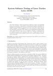
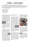
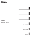
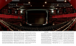
B.R.Harvey: Registation and Transformation of Multiple Site Terrestrial Laser Scanning REGISTRATION AND TRANSFORMATION OF MULTIPLE SITE TERRESTRIAL LASER SCANNING Bruce R. Harvey School of Surveying and Spatial Information Systems University of New South Wales [email protected] ABSTRACT Two computational methods for combining multiple scans of 3D terrestrial laser scanning data of an object are reported in this paper. One method is the ‘Registration’ process in Cyra’s Cyclone software that is associated with Cyrax laser scanners. The other method is least squares estimation of transformation parameters. The two methods provided similar but different solutions, each with advantages and disadvantages. Laser scanning experiments and software development have been used to investigate the combination of laser scans and with independent survey measurements of special targets. The accuracy of distance measurement between special scanning targets is also reported in this paper as being repeatable at about the ±1mm standard deviation level. Harvey, B.R. (2004) Registration and Transformation of Multiple Site Terrestrial Laser Scanning, Geomatics Research Aust., ISSN 1324-9983, No. 80 June 2004, pp. 33-50. 33 B.R.Harvey: Registation and Transformation of Multiple Site Terrestrial Laser Scanning 1. Introduction Terrestrial laser imaging systems offer relatively new means of effectively capturing massive quantities of precise real-time close range spatial data and modelling. The data is captured as a series of three dimensional coordinates. Terrestrial laser scanning has many applications and there are many interesting articles in journals, magazines and on the Internet (Raic, 2002). However, there is less published material on research into the testing of the instruments and their software. A Cyrax 2400 Laser Scanner and Cyclone software has been owned and tested at the School of Surveying and Spatial Information Systems, UNSW, since January 2001. A Cyrax 2500 has also been used on occasions in the research for this paper. Examples of our laser scan images, including high resolution colour and animated versions, from experiments described in this paper and other experiments, can be seen at www.gmat.unsw.edu.au/laser (as at April 2003). Cyrax scanners use rotating mirrors to direct a pulsed laser beam at a target area. From the measured distance and the orientations of the mirrors XYZ coordinates of points relative to the scanner’s origin can be obtained. In a few minutes the 3D coordinates of thousands of points can be measured with precisions of about 6 millimetres or better over ranges from a few metres to about 100 m. Surface fitting, such as centroids of targets, planes and cylinders can be more precise. This paper investigates multi-scan and multi-site laser scanning, discusses aspects of the least squares approach to transform the scanner’s coordinates to ‘ground truth’ coordinates, and describes the ‘registration’ approach in the Cyclone software package version 3 (Cyra, 2000) and version 4 (Cyra, 2002). The principles and methods used to merge (register) the images are similar to those used in photogrammetry and geodetic datum transformation. There are three main reasons for observing more the one scan and combining the data Harvey, B.R. (2004) Registration and Transformation of Multiple Site Terrestrial Laser Scanning, Geomatics Research Aust., ISSN 1324-9983, No. 80 June 2004, pp. 33-50. 34 B.R.Harvey: Registation and Transformation of Multiple Site Terrestrial Laser Scanning by registration or transformation. Firstly, Cyrax 2400 and 2500 scanners have a field of view of about 40 degrees horizontally and about 40 degrees vertically. So, to measure a greater field of view, for example the inside of an auditorium, multiple scans need to be observed and then combined in a manner similar to creating a panoramic view with a camera. Note that some other laser scanners have a larger field of view, up to a full 360°, and do not need to combine scans to form a panorama. However, also note that a panoramic view is not always required. There are many applications where the object to be scanned can be placed within a 40° field of view. Secondly, during a scan, only the points that reflect the laser beam to the instrument with sufficient return signal strength will be measured. So, with a single scan of an object, the scan image may have blank – shadow - areas where part of an object is hidden or occluded. For example a tree or pole in front of a building will obscure part of the building to be scanned. In this case the scanner can be setup in a second location to provide data for points in the shadow zone. The scans from each location are then combined. Finally, to scan all faces or components of an object it is often necessary to scan the object from multiple observation sites. For example, to scan all sides of a car a scanner would need to measure from at least two, possibly more, locations around the car. Also, to enable the production of ‘walk-throughs’ or ‘fly-throughs’, a number of scans will usually need to be measured and combined. 2. Cyrax Coordinate System and Targets The coordinate system used by Cyrax is a conventional right-handed system as shown in Figure 1. The axes are orientated with respect to the direction the scanner is pointing. The origin is at the zero point of the distance measurements. Unfortunately this is not at Harvey, B.R. (2004) Registration and Transformation of Multiple Site Terrestrial Laser Scanning, Geomatics Research Aust., ISSN 1324-9983, No. 80 June 2004, pp. 33-50. 35 B.R.Harvey: Registation and Transformation of Multiple Site Terrestrial Laser Scanning the intersection of the axes of the mechanical structure of the laser scanner. Therefore, if the scanner is rotated on its mount, about either or both axes, then there is a new coordinate system with a new origin and new orientation. Y Object to be scanned Laser path X Scanner Z Figure 1: Axes of the Cyrax coordinate system in relation to an object. When multiple scanner sites are used special targets are usually included in the view area. Often, though not necessarily, these targets are measured by independent survey methods and their coordinates determined in a particular coordinate system; for clarity we refer to them as ENH coordinates. The scanner measures the XYZ coordinates of these target points. In a subsequent analysis, the common points in the overlapping scan cloud can be transformed into a single coordinate system using a six-parameter transformation. The transformation parameters are determined between the scanned XYZ coordinates and the known ENH coordinates of these ‘common’ points. These transformation parameters are then applied to convert the scanned XYZ coordinates of the remainder of the scan cloud points into corresponding ground-based ENH coordinates. The inclusion of independent survey coordinates for target points will improve the accuracy and provide a measure of quality of scan surveys. Even if independent survey Harvey, B.R. (2004) Registration and Transformation of Multiple Site Terrestrial Laser Scanning, Geomatics Research Aust., ISSN 1324-9983, No. 80 June 2004, pp. 33-50. 36 B.R.Harvey: Registation and Transformation of Multiple Site Terrestrial Laser Scanning coordinates are not available, it is often necessary to combine (eg by transformation or registration) the scan data from two or more sites. Since the laser beam cannot be accurately pointed at a single point, the surface of a target is usually scanned. Then the “best fit” centre of the target is calculated. Consider three types of targets used with laser scanners: plane, cylinder and sphere. Cyra TiePoint square targets are bright green plane targets with a 32 mm diameter white circle in the centre as shown in Figure 2. Other versions of special targets also exist. Figure 2: Photograph of a Cyra target with the green laser dot in the top left hand corner. Theodolites and reflectorless EDM can also measure to these Cyra targets so that they can be connected to the desired coordinate system. It is often advantageous to mount the Cyra targets in a device that allows them to be accurately rotated, and perhaps tilted, about a point so that they face towards each of the multiple locations of a scanner or EDM. If a spherical target was used it would not need to be rotated, as it could be scanned from a location and calculations could determine the centre of the best fit sphere. However, only a small portion of a sphere’s surface will reflect the laser signal from a particular scanner location, thus reducing the accuracy of the coordinates of the centre of the sphere. Since in many applications it is rare to look down, or up, at steep angles to a target a cylindrical target would be almost as advantageous, in practice, as a sphere. A cylindrical target would not need to be turned, it could be scanned and the centre of the cylinder targeted. Harvey, B.R. (2004) Registration and Transformation of Multiple Site Terrestrial Laser Scanning, Geomatics Research Aust., ISSN 1324-9983, No. 80 June 2004, pp. 33-50. 37 B.R.Harvey: Registation and Transformation of Multiple Site Terrestrial Laser Scanning Lichti and Harvey (2002) reported on the effects of reflecting surface properties on laser scanner measurements. Several construction materials of different composition and surface roughness were tested, with both wet and dry surfaces. Scanning EDM prisms was not successful. Visual inspection of point clouds revealed significant range biases due to the saturation (excessive strength of return signal). Depending on the accuracy required, the common points can be features of the object being scanned rather than special targets. For example, if a man-made planar surface on an object is contained in more than one scan then it can be scanned and the parameters of best fit plane calculated in each scan. These parameters can be used in the transformation process. More details are given below. 3. ‘Registration’ by Cylone Software If one or more scans are measured without moving the scanner, they are aligned with respect to each other, ie they have a common coordinate frame. Cyclone defines a ScanWorld as a collection of scans that are all aligned to a common coordinate system. So scans within a ScanWorld can be combined directly. Scans, or ScanWorlds, with different coordinate systems, are combined through a calculation process called Registration in the Cyclone software (Cyra, 2000). Registration also allows users to combine multiple scans and to include ground survey data. The Cyclone registration process is similar to, but not the same as, least squares transformation. Each individual scanworld is treated like a rigid 3D object. Registration uses the coordinates of the target points to determine the rotation and translation of each scanworld with respect to one another, but no scale factor is determined or applied. Registration does not change the relative location of scan points within individual scans. (Cyra, 2001). Harvey, B.R. (2004) Registration and Transformation of Multiple Site Terrestrial Laser Scanning, Geomatics Research Aust., ISSN 1324-9983, No. 80 June 2004, pp. 33-50. 38 B.R.Harvey: Registation and Transformation of Multiple Site Terrestrial Laser Scanning Since Cyclone allows the registration of many scans with multiple coordinate frames at one time, it is not limited to pairs of scans. Cyclone also allows for registration to be done using common modelled objects (planes, lines, cylinders, etc) to form common constraints as well as the use of target (tie) points as common points. The locations of targets within each scan control how accurately multiple scans are combined. If independent survey coordinates of the targets are available, then there is no need for overlap between adjacent scans, as scans are registered to the surveyed control. The accuracy of registration, in this case, is dependent on the accuracy of the survey coordinates of the targets and on the accuracy of the scanning coordinates of the targets. The Cyclone software’s output from the registration process is limited. It produces ‘errors’ for each of the common points/features and allows the data for these common points to be weighted. However the software does not reveal all the information that would be present in a least squares transformation calculation, such as detailed statistical data input and output, and residuals for individual coordinate components. 3.1 Examples of Multi-Site Scanning Multi-site scanning is simply scanning an object from a number of different instrument sites. Field reconnaissance to decide the best locations of instrument and targets is necessary. If the scans contain at least 3 (preferably more) common target points in each scan, then the scans can be linked together through a registration process. An experiment was conducted to create a 3D model of the Naked Lady Statue located on the University of New South Wales campus. Scans were completed from four different scanner stations around the statue. All the scans were linked together by tie points to a local coordinate system to create a true 3D dimensional model of the statue. In another experiment, a yacht was scanned in a museum. Due to site constraints it was not Harvey, B.R. (2004) Registration and Transformation of Multiple Site Terrestrial Laser Scanning, Geomatics Research Aust., ISSN 1324-9983, No. 80 June 2004, pp. 33-50. 39 B.R.Harvey: Registation and Transformation of Multiple Site Terrestrial Laser Scanning possible to measure all of the yacht from one site. Targets were placed in the scene to aid registration but insufficient locations for targets were available. In addition to the targets, flat walls behind the yacht and parts of the yacht itself – sections of wire cable under tension – were used in the registration process. Often the software is able to acquire the target points automatically from a scan of the scene by detecting small bright objects in the scan. Alternatively the user can select parts of the scene to locate the actual target points. Once located, the targets are then scanned at a very fine resolution and the centroid coordinates calculated. In another experiment, the Red Centre Building at UNSW was scanned from locations that could not fit the face of the building within the field of view. Two adjoining and partially overlapping scans were taken and were successfully registered without using any targets. A number of coplanar patches and collinear cylinders, within the overlapping area, were used to register the two scans together. Details of the procedure and errors produced from registering the two scans together are given in Raic (2003). An experiment was also conducted to combine two scans from opposite sides of the Running Man statute at the Sydney Olympic site. The scans, from view points almost 180° opposed, were successfully registered by using lines of best fit to parts of supporting guy wires and without special targets in the scene. Images of the experiments are available on the web site quoted above. 4. Transformation by Least Squares The transformation of scanner (XYZ) coordinates to ground (ENH) coordinates for a single scanworld can be accomplished by a least squares solution of a six parameter orthogonal transformation from the data for a number of target points with known coordinates known in both reference systems. That is, the common target points’ Harvey, B.R. (2004) Registration and Transformation of Multiple Site Terrestrial Laser Scanning, Geomatics Research Aust., ISSN 1324-9983, No. 80 June 2004, pp. 33-50. 40 B.R.Harvey: Registation and Transformation of Multiple Site Terrestrial Laser Scanning coordinates can be used to determine the transformation parameters, and will enable the transformation of coordinates for the entire scanned object. The 6-parameter transformation as shown in Harvey (1998) is based on - ⎛E⎞ ⎜ ⎟ ⎜N⎟ = ⎜H ⎟ ⎝ ⎠ ⎛ x ⎞ ⎛ Tx ⎞ ⎜ ⎟ ⎜ ⎟ R ⎜ y ⎟ + ⎜ Ty ⎟ ⎜ z ⎟ ⎜ Tz ⎟ ⎝ ⎠ ⎝ ⎠ The six parameters are the three rotation angles and the three translations. The translations (Tx, Ty, Tz) are the coordinates of the origin of the xyz coordinates (the scanner centre) in the ENH frame. R is a 3x3 orthogonal rotation matrix that includes the three rotation angles about the axes of the xyz (scanner) system. A scale factor could be determined as a parameter in a 7 parameter adjustment or as a separate calculation as described below. However determining scale factors between scanning distances and survey measurements is likely to be only required in research and testing situations and not usually in regular operational scanning surveys. The equations and algorithms for a combined method Least Squares transformation are given in Harvey (1998). How fast a problem converges depends on the problem itself the better the initial approximations and the closer the model equations are to linear the faster the convergence. The translation terms are linear and their values are usually stable after one iteration. However, the rotation angles have to all be less than about 1 degree for the solution to be linear. If the starting values of the rotation angles are chosen to be 0° then many (eg 70) iterations of a least squares adjustment may be necessary. Good starting estimates of the rotation angles assist the speed and convergence of the least squares transformation solution. A method of determining starting estimates is described below. If the approximate direction (slope α and bearing β) from the scanner to the centre of the target area (ie the – Z axis direction) is estimated, then starting values of the rotation Harvey, B.R. (2004) Registration and Transformation of Multiple Site Terrestrial Laser Scanning, Geomatics Research Aust., ISSN 1324-9983, No. 80 June 2004, pp. 33-50. 41 B.R.Harvey: Registation and Transformation of Multiple Site Terrestrial Laser Scanning angles can be derived as follows. In practice, the scanner’s x axis will usually be close to horizontal. For the determination of approximate rotations, assume it is horizontal. If the slope angle α is positive above horizontal and negative below then a rotation about the x axis of (–90°-α) brings the z axis to vertical, ie parallel to the H axis, and the x and y axes into a horizontal plane. Finally a rotation about the z axis (now vertical) by β would align the two axis systems. So the approximate starting values of the rotation angles are: rotation about the scanner’s x axis ≈ -90°-α, about the y axis is ≈ 0, and about the z axis is ≈ β. In a least squares adjustment, the stochastic model must be correct as well as the mathematical model. Both the scanner XYZ coordinates of the points and their ENH coordinates are observations and may change when adjusted by least squares. In the Cyclone registration process this is not the case. Also note that, with either method, it is not necessary to hold the coordinates of any point fixed. The transformation solutions for multiple site surveys are an extension of the above model. If the scanner is tilted, rotated or moved to another location, then additional transformation parameters are required in the least squares solution. There are an additional six parameters for each additional scanner position or orientation. Some target points will be observed from more than one scanner position; so they will have one set of ENH coordinates and more than one set of XYZ coordinates. For some surveys, not all target points will be scanned from each scanner location. Obviously, software written for multi-site laser scanning transformations needs to be able to handle these conditions. The results of a transformation adjustment are two sets of adjusted coordinates that Harvey, B.R. (2004) Registration and Transformation of Multiple Site Terrestrial Laser Scanning, Geomatics Research Aust., ISSN 1324-9983, No. 80 June 2004, pp. 33-50. 42 B.R.Harvey: Registation and Transformation of Multiple Site Terrestrial Laser Scanning differ by the adjusted parameters. The changes to coordinates are usually small and the overall nature of the net does not change. So a transformation adjustment between the input and adjusted versions of a net will yield estimated rotation angles and translations all equal zero. It is advisable to statistically test the residuals and the estimated variance factor. 4.1 Simulations of Least Squares Transformation Simulations by Least Squares estimation are useful for planning scanning surveys. They assist with decisions about where to place target points and where to locate the instrument. It is not necessary to write special software to calculate simulations of adjustments. Nor is it necessary to add “noise” to perfect observations. The steps required in a simulation are: use knowledge of the site to select the locations of target points; determine approximate coordinates of the targets; select reasonable values for the standard deviations of the coordinates; solve the least squares transformation; and interpret the results. Even before any measurements are taken, it is possible to calculate reliable values of the correlations and standard deviations of parameters and adjusted coordinates, redundancy numbers of the observed coordinates and possible outlier detection characteristics. Such simulation studies have been carried out to determine the effects of the geometry of the location of target points, the effects of a limited field of view of a scanworld, and to study the effects of scanner and target location in multi site surveys. Questions that can be answered for specific scanning surveys include: Where is the best location for targets? What effects are there if the targets are coplanar (eg are all on one wall, or all on the ground)? What will be the reliability and precision of the transformed coordinates of points outside the region spanned by the targets used to derive the parameters? If the ENH coordinates of the scanner’s origin are unknown, but as a Harvey, B.R. (2004) Registration and Transformation of Multiple Site Terrestrial Laser Scanning, Geomatics Research Aust., ISSN 1324-9983, No. 80 June 2004, pp. 33-50. 43 B.R.Harvey: Registation and Transformation of Multiple Site Terrestrial Laser Scanning compromise a target is placed in the foreground of the scan scene, close to the scanner, will the quality of the survey improve? If the field of view actually scanned is less than the maximum field of view possible with the scanner, what will be the effects on quality of the transformation parameters and on the transformed coordinates? Wyers (2001) gives results for some simulations. In general, the accuracy of the estimated parameters may vary considerably depending on the spatial distribution of the points used. Targets should surround the object of prime interest, so that the transformation parameters are not extrapolated to points outside their scope. Also, there should be a target in the foreground, that is close to the scanner, to improve the solution for the transformation parameters. Targets should not be collinear because components of rotations about axes parallel to the line of points cannot be determined. For a stable solution it is also important that the points are well distributed spatially. A network with an uneven spread of points will bias the solution towards the areas of high density. This often causes points in areas of low density to have large corrections to their coordinates. One check for systematic errors or distortions is to compare the estimated transformation parameters from an adjustment using all targets with those from another solution where one target (the check point) is not included. If the changes in parameter estimates are acceptable, then the adjustment is stable and reliable. Also, transform the coordinates of the checkpoint in net A by the parameters determined by the second solution. Then compare the transformed coordinates with the coordinates in net B. 5. Comparison of Transformation Methods Transformations or registration can be applied to a single scan (or scanworld) to transform the scanner coordinates into a ground control survey coordinate system, or to Harvey, B.R. (2004) Registration and Transformation of Multiple Site Terrestrial Laser Scanning, Geomatics Research Aust., ISSN 1324-9983, No. 80 June 2004, pp. 33-50. 44 B.R.Harvey: Registation and Transformation of Multiple Site Terrestrial Laser Scanning scans from multiple instrument sites. The author has written transformation software that allows for multiple laser scanner sites but uses only target points as data; not lines, planes or cylinders. Data sets have been processed through both the transformation software and through Cyclone’s registration procedure. The registration calculations are faster than the least squares software, especially if the least squares solution requires many iterations. Generally, comparisons of the two methods show very small differences (a few mm) in the translational parameters between the Cyclone registration solution and that of least squares transformation. The rotational parameters output by Cyclone 3 are different to those of the least squares transformation model described above. Cyclone produces a single rotation angle about a single vector to represent the three rotational degrees of freedom. The least squares transformation on the other hand provides a rotation angle for each of the X, Y and Z axes. It is possible to convert from one system to the other. If α, β, γ are the direction cosines of the rotation axis, ρ the rotation about this vector and ω, φ, κ are the rotation angles about the X Y and Z axes, then Leahy (2001) proposes the following equations: sin ω/2 = sin ρ/2 cos α sin φ/2 = sin ρ/2 cos β sin κ/2 = sin ρ/2 cos γ sin2ρ/2 = sin2ω/2 + sin2φ/2 + sin2κ/2 In general, the residuals of the target coordinates appear to be smaller from the least squares solution than from the Cyclone solution. However, the differences between Cyclone registration and least squares solution are usually smaller than the specified measurement accuracies of scan points. The output from Cyclone’s registration shows an ‘error’ column, but this term is not exactly defined. Harvey, B.R. (2004) Registration and Transformation of Multiple Site Terrestrial Laser Scanning, Geomatics Research Aust., ISSN 1324-9983, No. 80 June 2004, pp. 33-50. 45 B.R.Harvey: Registation and Transformation of Multiple Site Terrestrial Laser Scanning 6. Accuracy of Coordinates and Distances The distances between the control target points can be calculated from Cartesian survey coordinates and can be compared with the distances between the targets obtained from the laser scanning. Some of the inter-target distances may be measured in more than one scanworld. Our experiences with a Cyrax 2400 show that the differences can be several millimetres. Note that the survey methods used to coordinate the target points should include check observations, but that the laser scanning does not include checks unless the targets are scanned in more than one scan and possibly from more than one scanner location. As well as combining the data sets using the transformation model described previously, we can investigate the scale factors (s = DG / DL , where DL is distance by laser scanner and DG is distance by ground survey) or differences in lengths (d = DG - DL) calculated from the lines between each pair of targets. Plotting and otherwise examing these scale factors, or the difference in lengths of lines, is useful for finding inconsistencies or outliers in the data. Experiments were undertaken to determine the accuracy of the distances between targets that a Cyrax 2400 can achieve (Raic, 2002 and Waud, 2003). A calibration pole with permanent targets placed precisely 2 m from centre of target to centre of target was placed about 50 m away from the scanner and other targets were placed nearer the scanner, as shown in figure 3. The targets were scanned in 10 epochs, moving the scanner only slightly (less than 0.5 m) each time. The experiment was first conducted in 2002 with no corrections made for atmospheric conditions (more details below). The experiment was independently repeated one year later, and corrections for atmospheric conditions were applied. Some of the results for the 2003 experiment are shown in Table 1. Harvey, B.R. (2004) Registration and Transformation of Multiple Site Terrestrial Laser Scanning, Geomatics Research Aust., ISSN 1324-9983, No. 80 June 2004, pp. 33-50. 46 B.R.Harvey: Registation and Transformation of Multiple Site Terrestrial Laser Scanning Target 2 Target 3 Cyrax 2400 Pole ~8m ~50m Target 1 Not to scale Figure 3: Plan view of repeat epoch scan set up Targets: 1 to 2 2 to 3 1 to 3 Standard deviation (mm) Mean distance (m) ±0.59 2.000 ±1.21 7.639 ±1.57 7.665 Table 1: Repetition survey, 10 epoch, results, 2003 6.1 Atmospheric Corrections for Cyrax Laser Measurements The refractive index of air affects the velocity of light and the geometry (curvature) of its path. The effects of the refractive index on coordinate measurement by a Cyrax laser scanner with a wavelength of 532 nm were calculated. For a 100 m laser path: an increase in atmospheric pressure leads to a decrease in the correction (3.6 mm over the range from 960 hPa to 1050 hPa), and an increase in temperature leads to an increase in the correction (4.3 mm over a range from 0°C to 45°C), but a change in the partial water vapour pressure (humidity) has no significant affect on the distance measurement (less than 0.005 of a millimetre). Harvey, B.R. (2004) Registration and Transformation of Multiple Site Terrestrial Laser Scanning, Geomatics Research Aust., ISSN 1324-9983, No. 80 June 2004, pp. 33-50. 47 B.R.Harvey: Registation and Transformation of Multiple Site Terrestrial Laser Scanning Thus, the refractivity correction can amount to 5 mm in some field conditions. This is a bias that is significant compared to the single point precision of Cyrax laser scans (specified as about ± 6 mm). Most of the tests for this research were done with Cylone software version 3 which does not have any input for temperature, pressure, etc. Cyclone version 3 did not perform any atmospheric correction - it assumed a refractive index of n = 1.0 (Cyra, 2003). There are two important points to note. Firstly, the refractivity effect is not just on distance, the effect is a scale error on the 3D coordinates. For example, if a flat wall normal to the scanner is measured, the wall would appear perhaps too far from the scanner and points on the wall would be spread apart, that is the wall would also be too high and too wide. Secondly, note that mathematical surfaces can be fit to sets of points (eg. a plane for a wall). The precision of the fit surface is often much better than individual point measurements (specified as ± 2 mm) and then the refraction effect becomes more significant. Similarly, the determined ‘vertex’ coordinates of a scanned target are more precise than single point measurements. If targets are used to determine the deformation of an object or region, the vectors between the targets can be determined very precisely and refractivity corrections should be applied. Our research now uses version 4 of Cyclone software. One of the new features of the software is the inclusion of atmospheric corrections using the Ciddor Fomulae (Ciddor, 1996) as per a resolution by the International Association of Geodesy in 1999. The Ciddor equation requires the following inputs: temperature, pressure, relative humidity, CO2 content and the wavelength of light emitted. Cyclone version 4 allows input of a ppm correction or temperature and pressure only, and assumes relative humidity = 60% and CO2 = 450 umol/mol (Cyra, 2003). The wavelength is 532 nanometres. Harvey, B.R. (2004) Registration and Transformation of Multiple Site Terrestrial Laser Scanning, Geomatics Research Aust., ISSN 1324-9983, No. 80 June 2004, pp. 33-50. 48 B.R.Harvey: Registation and Transformation of Multiple Site Terrestrial Laser Scanning 7. Conclusions Laser scanning experiments and software development have been used to investigate the combination of laser scans with other laser scans and with independent survey measurements of special targets. Algorithms and software for transformation by least squares were developed and comparisons made with Cyra’s Cyclone v3 and v4 software. The two methods provided similar but different solutions, each with advantages and disadvantages. Cyclone’s algorithms are fast and reliable at the Cyrax 2400 scanners specified point measurement accuracy of about ±5 mm (std. dev.), and allow the use of scanned and modelled surfaces to assist registration as well as target points. Independent analysis by least squares allows more thorough investigation of the transformation or registration of scan clouds, especially the statistical nature of the results. Thorough least squares analysis is also valuable when considering that vector distances between special scan targets can be measured at about millimetre accuracy. 8. References Ciddor, P.E. (1996) Refractive Index of air: new equations for the visible and near infrared. Applied Optics, Vol.35, No.9, 1566-1573 Cyra, (2000) Cyclone 3.0 User’s Manual, Cyra Technologies, Inc. Oakland, CA, USA Cyra, (2001) Cyrax and Cyclone Basic Training Course Document, Cyra Technologies, Inc. Oakland, CA, USA Cyra, (2002) Cyclone 4.0 User’s Manual, Cyra Technologies, Inc. Oakland, CA, USA Cyra, (2003) Personal communications with Krassi Sotirova, Applications Engineer, Cyra Technologies, Inc. Harvey, BR. 1998. Practical Least Squares and Statistics for Surveyors, 2nd ed., Geomatic Engineering, UNSW. Harvey, B.R. (2004) Registration and Transformation of Multiple Site Terrestrial Laser Scanning, Geomatics Research Aust., ISSN 1324-9983, No. 80 June 2004, pp. 33-50. 49 B.R.Harvey: Registation and Transformation of Multiple Site Terrestrial Laser Scanning Leahy, F. J. (2001) The rotation of solid bodies around skewed axes. Unpublished – Draft paper. University of Melbourne. Lichti, D.D. and B R Harvey (2002) An Investigation into the Effects of Reflecting Surface Material Properties on Terrestrial Laser Scanner Measurements. Geomatics Research Aust. No. 76 June 2002, pp. 1-22. Raic, J (2002) Terrestrial Laser Scanning, GMAT4001 Thesis, Supervisor: BR Harvey, School of Surveying and Spatial Information Systems, The University of New South Wales, October 2002. Waud, M (2003) Terrestrial Laser Scanning, GMAT4001 Thesis, Supervisor: BR Harvey, School of Surveying and Spatial Information Systems, The University of New South Wales, October 2003. Wyers, G.R. (2001) Laser Scanning Experiments, GMAT4001 Thesis, Supervisor: BR Harvey, School of Surveying and Spatial Information Systems, The University of New South Wales, October 2001. Harvey, B.R. (2004) Registration and Transformation of Multiple Site Terrestrial Laser Scanning, Geomatics Research Aust., ISSN 1324-9983, No. 80 June 2004, pp. 33-50. 50