1
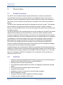
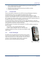
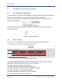
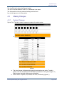
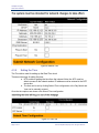
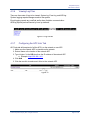
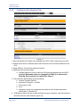
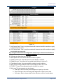
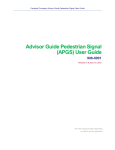
Advisor Advanced Pedestrian System (AAPS) User’s Manual 906-0005 Version F ● January 30, 2015 Campbell Company AAPS User’s Manual Campbell Company 450 W. McGregor Drive Boise, Idaho 83705 USA Tel: 1-208-345-7459 Fax: 1-208-345-7481 Last edited: 30 January 2015 This document is copyright © 30 January 2015 by Dick Campbell Company. All rights reserved. No part of this publication may be reproduced, transmitted, transcribed, stored in a retrieval system, or translated into any language, in any form or by any means, electronic, mechanical, photocopying, recording, or otherwise, without prior written permission from Campbell Company. All copyright, confidential information, patents, design rights and all other intellectual property rights of whatsoever nature contained herein are and shall remain the sole and exclusive property of Campbell Company. The information furnished herein is believed to be accurate and reliable. However, no responsibility is assumed by Campbell Company for its use, or for any infringements of patents or other rights of third parties resulting from its use. The Dick Campbell Company name and Campbell Company logo are trademarks or registered trademarks of Campbell Company. All other trademarks are the property of their respective owners Page 2 of 21 906-0005 AAPS Users Manual Rev F © Dick Campbell Company 2015. All rights reserved Campbell Company AAPS User’s Manual AAPS User’s Manual 906-0005 Revision History Revision Revised By Date A Tony Brennan 07-19-2012 B Zane Sapp 11-01-2012 C Zane Sapp 05-10-2014 D Cody Browne 10-13-2014 E Cody Browne 11-21-2014 F Zane Sapp 1-30-2015 Firmware and Software Versions Component Version Date APC Firmware 3.2.0 01-27-2015 APB Firmware 2.3.7 01-27-2015 906-0005 AAPS Users Manual Rev F © Dick Campbell Company 2015. All rights reserved Page 3 of 21 Campbell Company AAPS User’s Manual 1 Table of Contents 1 Table of Contents ................................................................................................... 4 2 Introduction............................................................................................................. 5 2.1 PURPOSE OF THIS DOCUMENT....................................................................................................... 5 2.2 ADDITIONAL INFORMATION ............................................................................................................ 5 2.3 CONTACT INFORMATION ............................................................................................................... 5 3 Overview ................................................................................................................ 6 3.1 PRODUCT OVERVIEW ................................................................................................................... 6 3.2 FEATURES .................................................................................................................................. 6 3.3 COMPONENTS ............................................................................................................................. 7 3.4 AUDIO MESSAGES ....................................................................................................................... 7 4 System Configuration ............................................................................................. 8 4.1 ACCESSING THE W EBPAGE ........................................................................................................... 8 4.2 MAIN SCREEN ............................................................................................................................. 8 4.3 MAKING CHANGES ....................................................................................................................... 9 5 6 Troubleshooting.................................................................................................... 18 5.1 APC TROUBLESHOOTING ........................................................................................................... 18 5.2 RUNNING A PATCH ..................................................................................................................... 19 5.3 APB TROUBLESHOOTING............................................................................................................ 19 Appendix A: Acronyms, Abbreviations & Definitions ............................................ 21 Page 4 of 21 906-0005 AAPS Users Manual Rev F © Dick Campbell Company 2015. All rights reserved Campbell Company AAPS User’s Manual 2 Introduction 2.1 Purpose of this Document The purpose of the document is to describe the operation of the Advisor Advanced Pedestrian System (AAPS).This document doesn’t cover the installation of the AAPS. 2.2 • • • • 2.3 Additional Information See the AAPS Installation Guide for installation instructions. Reference the Campbell Company Intersection Worksheet for location specific information. Set the AAPS Installation Quick Guide for a brief graphical installation guide. See the Base Station Mounting Template for an easy to use hole pattern for mounting APBs. Contact Information The first line of contact should be the distributor that the system was purchased from. If you are unable to contact the distributor, contact Campbell Company directly. 906-0005 AAPS Users Manual Rev F © Dick Campbell Company 2015. All rights reserved Page 5 of 21 Campbell Company AAPS User’s Manual 3 Overview 3.1 Product Overview The AAPS is an Accessible Pedestrian Signal (APS) based on network communications. Communication from the traffic controller cabinet to the pedestrian station is done over two conductors. Power for the pedestrian stations is also provided on the same two conductors. In many cases, the two conductors are already at the intersection from the previous pedestrian system. The AAPS uses a webpage based interface to manage and monitor the system. This webpage can be viewed on any device with a network connection to the APC. Desktop computers, laptops, and even handheld devices can connect and operate the system as long as they share a network connection. The AAPS provides all of the standard features for an APS as defined by the MUTCD as well as additional features based on local specifications. A locator tone tells a pedestrian that the crossing is equipped with APS and where it can be found. An extended press provides specific intersection information and access to additional functions. The audible walk tone or message is accompanied by a vibro-tactile indication during the visual walk display. Optional clearance phase indications may provide additional information to the pedestrian where appropriate. Each AAPS is pre-configured at the factory based on the documentation provided by the customer. Configuring the AAPS can be done entirely though the APC management webpage, so the customer can re-configure the system as needed. Campbell Company cannot guarantee the AAPS will work properly with all existing field wiring, especially if a single common to the buttons and signal lighting is shared. Each case will have to be tried and proven because it depends on the condition of the wires, splices, etc. In the event there are no field wires, AAPS can be swapped out for an alternative as long as there is no damage to the AAPS units. 3.2 • • • • • • • • • Features Capable of using existing pedestrian field wiring to provide power and communication to the push button stations reducing costs in retrofit installations Ethernet access for remote communication All configurable settings available over network via webpage including audio message upload Time of day functions including night time audio volumes Pedestrian call count data Independent volumes for locator and non-locator audio messages Station independent volumes Automatic Gain Control (AGC) available for all audio messages Accepts any audio message in WAV format Page 6 of 21 906-0005 AAPS Users Manual Rev F © Dick Campbell Company 2015. All rights reserved Campbell Company AAPS User’s Manual • • • 3.3 Audio messages and station configuration backed up on the APC enables quick recovery after a station knock-down Clearance interval options including beaconing and audible countdown Preemption options available Components There are three primary components to the AAPS; the Advanced Pedestrian Controller, a Termination Board, and one or more Advanced Pedestrian Button (APB). The APC is the center point of the AAPS. It provides both power and pedestrian signal information to all of the APBs. The APC is also the point at which the system is configured. The APC is located in the traffic controller cabinet. It connects to the 120VAC load switch outputs for the pedestrian signals and the low voltage pedestrian call inputs. The Termination Board is located in the traffic controller cabinet with the APC. It provides a convenient place to land all of the field connections to the APBs. The Termination also provides current protection to each field connection individually. The APB is the point of interaction with the pedestrian. The APB is available in several form factors including: • Base Station: A fully integrated pedestrian station • 400(A): A station designed to drop into a 400 style frame In addition to different form factors, the stations are available in a wide range of colors. 3.4 Audio Messages The AAPS comes fully programmed with audio files from the factory but we give you the option to create your own custom messages in a simple .wav format that can be easily uploaded via the APC network connection. Second languages, gender narrative, and special percussive tones can be easily created and uploaded. Figure 1. Base Station 906-0005 AAPS Users Manual Rev F © Dick Campbell Company 2015. All rights reserved Page 7 of 21 Campbell Company AAPS User’s Manual 4 System Configuration 4.1 Accessing the Webpage To make changes and view the AAPS webpage simply plug an Ethernet cable into the Ethernet port on the front of the APC. Then connect the Ethernet cable into your laptop. Start up a web browser such as Google Chrome and type in the IP 192.168.1.101 into the address bar. (See Below) Figure 2 Webpage Address bar You will see the following screen pop up looking for credentials. Default user name: admin Password: password. Figure 3 Authentication Page 4.2 Main Screen The first screen is shown below it gives the status of the pedestrian system (figure 4.) To view this screen click “Here” to enable real time status Figure 4 Status Page The Pedestrian Signal Status shows the state of the Signal (DW, FDW, W) and if a call has been placed. Stations Status bar will show a state of the stations; The Status tab gives an overview of the system. The System tab allows for global settings to be adjusted. The Station tab allows for individual station settings to be adjusted. The Sound tab allows for audio files to be changed. The Network tab allows for changes to the APC IP address. The Time tab allows for the time to be adjusted. Page 8 of 21 906-0005 AAPS Users Manual Rev F © Dick Campbell Company 2015. All rights reserved Campbell Company AAPS User’s Manual The Log Files tab is where log files are located The APC Links tab allows for all APC’s IP addresses to be stored The Advanced tab is where advanced settings can be found. Log out tab logs you out of the system. 4.3 Making Changes 4.3.1 System Changes System Tab: This tab is where changes are made to the entire system a. Figure 5 a. The check boxes at the beginning signify what stations are active. To add a station, click the checkbox and it will add more stations to the system (figure 5.) Black means checked, white means unchecked. b. AAPS mode: 4 options; Off, Default, EP APS, and Identify (figure 5.) 906-0005 AAPS Users Manual Rev F © Dick Campbell Company 2015. All rights reserved Page 9 of 21 Campbell Company AAPS User’s Manual c. d. e. f. g. h. i. j. k. l. m. n. o. p. q. Page 10 of 21 i. Off behaves like a typical button, places calls, no Audio ii. Default is normal APS operation iii. EP APS only actuates APS audio when an extended press is placed iv. Identify will put the APB’s into a mode where their LED’s will blink the assigned station ID (troubleshooting) Extra-press mode: places two calls to the traffic controller one for current cycle and one for following cycle Vib Call Pulse: Allows for vibrotactile feedback when the button is pressed Auto Recall: When checked constant calls will occur if a button is at ATTN Locator AGC: When checked locator AGC will be enabled. If un-checked locator tone will be constant Night mode: Check the box to enable and then set the time for the hours that you would like to adjust the volume differently Clearance mode: 5 options Off (no Beaconing), Ping Pong, Dest/Init beaconing and Audible countdown. i. Destination beaconing implements beaconing (only the destination APB will beacon in the clearance phase) ii. Initiation beaconing implements beaconing at the initiation station only. iii. Audio Countdown: audible countdown will be enabled iv. Ping-Pong: Buttons on each side of the street will alternate in FDW AGC responsiveness: Adjusts how quickly the ambient gain responds. (1-20, 20 least responsive) Walk message Timeout: Refers to a rest in walk situation, adjusts the time the walk message will timeout without being interrupted by the flashing don’t walk. Extended press time: Adjusts the length time required to place an extended press or APS call. Repeated Acknowledgement: Number of seconds between each repeated acknowledgement message (0 means no repeat) APB Protocol: BSON V1 (2.2.0 -3.0.0) is the default setting. If buttons are not communicating try setting to the older version (1.5.1-2.1.0) Intersection Interface: Default setting is 120V I/O. This setting can be changed to Simulator only when in a benchtop testing application. Setting should remain at 120V I/O or pre-timed values will run for Walk and Don’t Walk. “Save System Configuration to APC” button: Will save all changes to APC “Save and Send Changed Settings” button: Will Save and send only changed settings. “Save and send All settings” button: Will send all settings. 906-0005 AAPS Users Manual Rev F © Dick Campbell Company 2015. All rights reserved Campbell Company AAPS User’s Manual 4.3.2 Changing Station Settings The most common changes will have to do with the Station tab Shown Below. Figure 6 Station Tab All active stations will be shown in this tab. To change the Signal (phase) of the button, change the Phase number. To change the group of the button, change the Group number To change the volume level, enter a number between -300 and +300. Defaults are shown above. In order to make the changes permanent click: 906-0005 AAPS Users Manual Rev F © Dick Campbell Company 2015. All rights reserved Page 11 of 21 Campbell Company AAPS User’s Manual a. “Save APB Configuration to APC” button: Will save all changes to APC b. “Save and Send Changed Settings” button: Will Save and send only changed settings to the buttons. c. “Save and Send All settings” button: Will send all settings. Buttons with ID’s can be changed back to “new.” Simple change old station ID to be the ID of the button you want to be “new” leave New station ID at New and click “Change ID”. 4.3.3 Changing Audio files The Sound File tab allows for audio files to be uploaded to individual stations. a. First add sound files to the file system. Click Choose Files/ select them/ then click “Upload to APC.” b. Next find the message that you will be changing the audio files on. c. Simply click on the dropdown box and select each audio file for each message on each station slot (figure 8) d. Click the Red “Send” button in the matrix (figure 7) to send all audio files to the ped stations. e. Message that is to be sent is on the left. “All messages” button is one from the bottom and in Orange. If you want to send all messages to a single station select the All Messages orange “send” button at the bottom. If you want to send a specific message to all stations, click the All Stations orange “Send” button at the right. Figure 7 Audio send Matrix Page 12 of 21 906-0005 AAPS Users Manual Rev F © Dick Campbell Company 2015. All rights reserved Campbell Company AAPS User’s Manual Figure 8 Setting up audio files 4.3.4 Changing APC IP In order to remotely communicate with the APC the IP address must be set up. a. Before changing settings consult you IT Department. Also, remember that the IP address is how access is granted to the webpage. If the IP address is changed document it! If IP address is lost hold B1 Button on front of APC and boot (turn on the unit.) IP will be reset. 906-0005 AAPS Users Manual Rev F © Dick Campbell Company 2015. All rights reserved Page 13 of 21 Campbell Company AAPS User’s Manual Figure 9 Network Tab 4.3.5 Setting the Time The Time tab is used for setting up the Real Time clock There are two ways of setting the time: a. NTP enable or getting the time from the internet. Note: the APC must be able to access to the network and an IP address must be entered in the NTP server box. b. The time can be set by clicking Submit Time configuration or the Day Month and Year can be manually entered. Once the time options are chosen click Submit Time configuration. Figure 10 Time Tab Page 14 of 21 906-0005 AAPS Users Manual Rev F © Dick Campbell Company 2015. All rights reserved Campbell Company AAPS User’s Manual 4.3.6 Viewing Log Files There are three sets of logs to be viewed: System log, Event log, and APB log. System logging reports changes made to the system. Event logging reports any conflicts and/or loss of station communication APB log reports ped call counts by hour by station # Figure 11 Log File tab 4.3.7 Configuring the APC Link Tab APC links tab will keep track of all the APC’s on the network on one APC. 1. Make sure the network APC is viewable on the network. 2. Enter a Name or the location of the network APC 3. Type in https:// in the URL box then the IP address of the network APC a. Example: http://192.168.1.101 4. Click Add 5. Click the new link to make sure it links to the network APC Figure 12 906-0005 AAPS Users Manual Rev F © Dick Campbell Company 2015. All rights reserved Page 15 of 21 Campbell Company AAPS User’s Manual 4.3.8 1. 2. 3. 4. 5. 6. Configuring the Advanced Tab Figure 13 New Configuration file is able to be uploaded to the APC. Older versions may not work. Reboot button will do a software reboot. Must be done to set time and IP address for the APC. Reset APB log. This will clear the button log files. Additional users can be created a. Change password: click on edit user: Will reset the password on the AAPS webpage (Remember what you changed it to! Mark it on Intersection Planning Sheet and store in cabinet Doc Sleeve.) The intersection identification can be found here: a. Location Example: Boise ID b. Intersection: Example: 1st at Main c. CC# (order #) 1234 d. PO # e. Intersection image can be selected here and then click “Submit Intersection Identification” to update APC APB Memory allows the user to wipe the button memory completely, view files stored on the button and also view firmware. (figure 14) Page 16 of 21 906-0005 AAPS Users Manual Rev F © Dick Campbell Company 2015. All rights reserved Campbell Company AAPS User’s Manual Figure 14 7. Ped Closure Dwell: Time in (ms) the contacts will closed to the traffic controller to signify a normal press was made. 8. APS Closure Dwell: Time in (ms) the contacts will closed to the traffic controller to signify an extended press was made. Any changes to the advanced configuration should only be done at the direction of Campbell Company. 9. CID scan rate: How often the I/O is read. 10. APB update rate: How often the buttons receive an update. 11. Display Update rate: How often the Front panel display is updated. 12. Display timeout: Time before the front panel display times out (shuts off) 13. Countdown Number: How many audible numbers to send to stations 14. APB Timeout tuning parameter: Sets time to display a station as “ATTN” 15. PVPRHT: Timeout for enabling button after vibration has ceased 16. Wire map: The wire mapping can be changed a. Walk input: Able to choose phase assignment of pins by color code. b. Don’t walk Input: Able to choose phase assignment of pins by color code. c. Call output: Able to choose what Pin/wire will place a call on a certain phase. 906-0005 AAPS Users Manual Rev F © Dick Campbell Company 2015. All rights reserved Page 17 of 21 Campbell Company AAPS User’s Manual 5 Troubleshooting The following chapter discusses troubleshooting the AAPS system in three parts: APC, Running Patches and APB. 5.1 APC Troubleshooting 1. Check Status light on front panel of the APC (RED and Green). Both should be blinking, RED at a fast speed signifying communication with the buttons, and Green at a ½ second rate. a. If LED light’s (green/red) have stopped blinking (solid on/off) Contact Campbell Company for assistance. Figure 15 LED’s/ Screen b. Status screen showing buttons that are running (up arrows) and buttons that are not communicating (down arrows.) 2. No Communication to APC a. Check computer’s IP address i. Hold Windows key+ R and then type in “cmd” and hit enter Figure 16 Showing connection and IP address 1. A prompt will appear (figure 13) ii. Type ipconfig and hit Enter iii. Look at local area connection Page 18 of 21 906-0005 AAPS Users Manual Rev F © Dick Campbell Company 2015. All rights reserved Campbell Company AAPS User’s Manual iv. Make sure IP has the first same three octets (192.168.1) and the last octet is not the same as the APC’s (101) OR that it is not 255 or 1. b. Type the APC’s address in web browser ie: 192.168.1.101 c. If no connection check for LED on computer’s Ethernet port i. Also can try “pinging” APC ii. Open Command prompt (type cmd in the search bar and hit enter) iii. Type ping 192.168.1.101 then Enter iv. The APC will reply if the computer IP is configured properly 5.2 Running a Patch 1. Make sure there is communication with the APC (see above) 2. Download patch folder from Dropbox and Extract All (right click and choose the option below) 3. Open patch folder (the unzipped one) and open the ips text document i. Add the IP address of the APC unit in the ips text doc and save 4. Double click on patch (windows batch file) 5. Click yes to any warnings 6. Once the patch is done it will say “Press any key to continue” Figure 17 Extracting Patch Figure 18 Patch 5.3 APB Troubleshooting When troubleshooting button problems, first start by bringing up the APC’s webpage. 5.3.1 APB Communication issues 1. First check voltage on the APB. Should be 16-18 VAC. a. If Voltage is at ~4 VAC the fuse has tripped. b. If Voltage is at 0 VAC it is possible lightning has destroyed the termination board fusing. Check for short. Warning this may cause APC to shut off. c. Power cycle and check voltage. If fuse trips again disconnect button and power cycle. Voltage correct? 906-0005 AAPS Users Manual Rev F © Dick Campbell Company 2015. All rights reserved Page 19 of 21 Campbell Company AAPS User’s Manual 2. 3. 4. 5. 6. 1. Yes Replace button 2. NoOhm wiring for shorts If APB is not communicating you will see ATTN and a red light in the station box (webpage) or a down arrow on the station number (front screen). Start up the station tab on the APC. If the station that has lost communication is station 1 then the first step would be to try changing the station number. Set up the Change Station ID to the figure shown below and click change. If the button’s ID is zero it will come back up in 15 seconds. If an error “button not found” is displayed go to the System tab and uncheck the station that is not communicating. (Meaning remove the button from the system.) Then click submit changes. Wait for approximately 30 seconds Ctrl-r will refresh the page. Next go back to the system tab and click the station back into the system. Click Submit System Configuration. 5.3.2 Calls placed on two phases 1. If one button press places calls on two phases check the grouping (Station Tab). This usually means a grouped button is on an improper phase.(figure 19) 2. To fix, simply change the grouping to be correct. 3. Typically all buttons on a phase are grouped together Figure 19 Station Settings Page 20 of 21 906-0005 AAPS Users Manual Rev F © Dick Campbell Company 2015. All rights reserved Campbell Company AAPS User’s Manual 6 Appendix A: Acronyms, Abbreviations & Definitions Term Meaning Accessible Pedestrian Signal (APS) A device that communicates information about pedestrian timing in a nonvisual format such as audible tones, verbal messages, and/or vibrating surfaces (MUTCD) Actuated operation A type of traffic control signal operation in which some or all signal phases are operated on the basis of actuation (MUTCD) Audible Beaconing Use of sound source to provide directional orientation and alignment information. Automatic Gain Control (AGC) An APS volume control that is automatically responsive to ambient (background) sound. Base Station Fully integrated APS station that contains the Mico-controller, push button, speaker, adapter plate DHCP Any portion of a roadway at an intersection or elsewhere distinctly indicated for pedestrian crossing by lines of other marking on the surface (MUTCD) Dynamic Host Configuration Protocol EoP Ethernet over Powerline Night Mode Ability to change audio volumes by time of day Phase Pedestrian Signal Designation Crosswalk 906-0005 AAPS Users Manual Rev F © Dick Campbell Company 2015. All rights reserved Page 21 of 21